EP1494537B1 - Automatisches band-kochgerät für pfannkuchen oder dergleichen - Google Patents
Automatisches band-kochgerät für pfannkuchen oder dergleichen Download PDFInfo
- Publication number
- EP1494537B1 EP1494537B1 EP02776609A EP02776609A EP1494537B1 EP 1494537 B1 EP1494537 B1 EP 1494537B1 EP 02776609 A EP02776609 A EP 02776609A EP 02776609 A EP02776609 A EP 02776609A EP 1494537 B1 EP1494537 B1 EP 1494537B1
- Authority
- EP
- European Patent Office
- Prior art keywords
- belt
- food
- run
- cooked
- top run
- Prior art date
- Legal status (The legal status is an assumption and is not a legal conclusion. Google has not performed a legal analysis and makes no representation as to the accuracy of the status listed.)
- Expired - Lifetime
Links
- 238000010411 cooking Methods 0.000 title claims abstract description 33
- 235000012771 pancakes Nutrition 0.000 title abstract description 32
- 235000013305 food Nutrition 0.000 claims abstract description 81
- 238000010438 heat treatment Methods 0.000 claims abstract description 14
- 239000007789 gas Substances 0.000 claims description 9
- 230000000694 effects Effects 0.000 claims description 6
- 238000003825 pressing Methods 0.000 claims description 2
- 238000011144 upstream manufacturing Methods 0.000 claims description 2
- 238000000034 method Methods 0.000 description 6
- 230000002572 peristaltic effect Effects 0.000 description 4
- 230000008569 process Effects 0.000 description 4
- 239000004809 Teflon Substances 0.000 description 3
- 229920006362 Teflon® Polymers 0.000 description 3
- 230000009471 action Effects 0.000 description 3
- 230000009172 bursting Effects 0.000 description 3
- 239000007788 liquid Substances 0.000 description 3
- 238000005086 pumping Methods 0.000 description 3
- 239000000853 adhesive Substances 0.000 description 2
- 238000004140 cleaning Methods 0.000 description 2
- 238000010276 construction Methods 0.000 description 2
- 230000003247 decreasing effect Effects 0.000 description 2
- 238000004049 embossing Methods 0.000 description 2
- 239000004744 fabric Substances 0.000 description 2
- 239000011152 fibreglass Substances 0.000 description 2
- 239000000463 material Substances 0.000 description 2
- 239000000203 mixture Substances 0.000 description 2
- 238000000926 separation method Methods 0.000 description 2
- 241000251468 Actinopterygii Species 0.000 description 1
- 241000287828 Gallus gallus Species 0.000 description 1
- 230000008901 benefit Effects 0.000 description 1
- 230000008859 change Effects 0.000 description 1
- 239000004020 conductor Substances 0.000 description 1
- 230000007423 decrease Effects 0.000 description 1
- 238000002845 discoloration Methods 0.000 description 1
- 230000009977 dual effect Effects 0.000 description 1
- 238000005530 etching Methods 0.000 description 1
- 238000000605 extraction Methods 0.000 description 1
- 230000010006 flight Effects 0.000 description 1
- 239000011888 foil Substances 0.000 description 1
- 239000012634 fragment Substances 0.000 description 1
- 230000033001 locomotion Effects 0.000 description 1
- 235000013372 meat Nutrition 0.000 description 1
- 230000007246 mechanism Effects 0.000 description 1
- 238000002156 mixing Methods 0.000 description 1
- 238000012986 modification Methods 0.000 description 1
- 230000004048 modification Effects 0.000 description 1
- 239000003973 paint Substances 0.000 description 1
- 230000001737 promoting effect Effects 0.000 description 1
- 230000001105 regulatory effect Effects 0.000 description 1
- 238000009987 spinning Methods 0.000 description 1
- 239000000126 substance Substances 0.000 description 1
- BFKJFAAPBSQJPD-UHFFFAOYSA-N tetrafluoroethene Chemical compound FC(F)=C(F)F BFKJFAAPBSQJPD-UHFFFAOYSA-N 0.000 description 1
Images


Classifications
-
- A—HUMAN NECESSITIES
- A21—BAKING; EDIBLE DOUGHS
- A21B—BAKERS' OVENS; MACHINES OR EQUIPMENT FOR BAKING
- A21B5/00—Baking apparatus for special goods; Other baking apparatus
- A21B5/02—Apparatus for baking hollow articles, waffles, pastry, biscuits, or the like
- A21B5/03—Apparatus for baking hollow articles, waffles, pastry, biscuits, or the like for baking pancakes
Definitions
- the present invention relates to an automated belt cooking machine for pancakes or the like food products.
- the present invention relates to an improved machine for cooking pancakes by dispensing a liquid batter onto a movable thermally conductive belt and bringing the liquid batter into thermal contact with upper and lower electrically heated platens or hot plates.
- the present invention relates to such an improved machine having a pair of overlapping, counter-rotating, thermally conductive belts in which the liquid batter is deposited onto a lower or underlying belt in thermal contact with a lower platen and then conveyed in the direction of an upper or overlying belt in thermal contact with an upper platen so that the batter enters the mouth between the counter-rotating belts with its bottom surface first exposed to heating before its top surface, thereby assisting in the release of gases trapped in bubbles produced by heating the batter before the batter becomes sandwiched between the belts, thus avoiding disrupting the structure of the cooked pancake.
- Automated belt cooking machines have been used in the prior art to cook certain food products, such as pancakes, meat patties, and fillets of fish and chicken.
- the prior art includes single belt cooking machines, particularly of the bar type or open mesh conveyor type, series belt cooking machines, and overlapping belt cooking machines.
- Single belt cooking machines though commonplace, are illsuited for cooking food products that require the application of heat to the top and bottom of the food to be cooked.
- the gases are likely to be released violently from the sides or bottom of the food being cooked, lending to a disrupted structure of the cooked food.
- the direct contact between the platens and the food and the likely bursting of bubbles requires that the platens be cleaned regularly, meaning that the machinery will suffer down-time resulting in lost productivity during a cool down and cleaning period.
- the open structure of the single conveyor used in the above patents means that the food is likely to break up or become embedded in the open structure, therefore requiring cleaning of the conveyor and surrounding structures to remove the baked on fragments of the food.
- a pair of opposed, counter-rotating belts convey the food between heated upper and lower platens which are in thermal contact with the portions of the upper and lower belts respectively that make contact with the food, so that heat generated by the platens is conducted through the belts and into the top and bottom of the food to be cooked.
- the superimposed location of the upper and lower platens is such that the food to be cooked is exposed to heat conducted through both the upper and lower belts simultaneously, and the parallel disposition of the upper and lower platens is such that no allowance is made for the usual increase in thickness of the food as it is being cooked between the platens.
- the simultaneous application of heat to the top and bottom surfaces of the food whilst the food is sandwiched and conveyed between the counter-rotating belts does not allow, it is assumed, for the gradual and peaceful release of gases trapped in bubbles formed on the surface of the food, particularly from the top of the food, causing disruption of the interior and surface structure of the food product as the bubbles burst out of the sides of the food.
- WO-A-96/16584 discloses an automated belt cooking machine for preparing food products comprising upper and lower overlapping, thermally conductive belts, said belts counter-rotatably mounted to a frame for said machine so that, in use, a bottom run of said upper belt and a top run of said lower belt co-operate to convey food to be cooked into said food products between said upper and lower belts, said lower belt extending a predetermined distance to one side of said upper belt so as to provide a dispensing platform portion of said top run of said lower belt for dispensing thereon said food to be cooked, so that, in use, said food is conveyed in a direction towards a mouth formed between said bottom run of the upper belt and said top run of the lower belt to receive said food and thereafter is conveyed sandwiched between said bottom run and said top run to a downstream end of said lower belt, upper and lower heating platens mounted to said frame above and below said bottom run of the upper belt and said top run of the lower belt, respectively, wherein said food to be cooked is
- said machine includes a dispensing apparatus for said food having a dispensing outlet located substantially over said dispensing platform portion.
- said bottom run of the upper belt and said top run of the lower belt converge towards said mouth formed between said bottom and top runs to receive said food.
- said upper platen is pivotally mounted to said frame so as to allow for adjustment or variation in the distance between said lower and upper platens to accommodate different thicknesses and expansion of said food being cooked.
- the upper platen may be pivotally mounted adjacent said mouth and may be subject to a pivotal bias for retaining a predetermined distance between said lower and upper platens provided by a spring means.
- said machine includes an antiroller mounted to said frame adjacent said downstream end of said lower belt, said antiroller and said lower belt being adapted to rotate in the same direction so that, in use, said food products are peeled off said lower belt by the rotation of said antiroller.
- a similar antiroller arrangement is preferably mounted adjacent the downstream end of said upper belt.
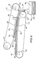
- the automated belt cooking machine 10 shown In Fig 1 includes an upper belt 12 and a lower belt 14 mounted to a frame 16.
- the upper belt 12 is rotated in an anticlockwise direction over motor driven roller 18 and idler roller 20, and the lower belt 14 is rotated in a clockwise direction over motor driven roller 22 and idler roller 24.
- the upper and lower belts 12, 14 are, in this embodiment, fabricated of a thin fibreglass fabric coated with Teflon, to provide sufficient flexibility, high temperature resistance, thermal conductance, and non-stick characteristics to releasably support and cook most foods.
- the upper belt 12 surrounds an upper heating platen 26, and the lower belt 14 surrounds a lower heating platen 28, the platens 26, 28 being heated electrically in this embodiment.
- the platens 26, 28 are in thermal contact with sections of the bottom and top runs 30, 32 respectively, of the belts 12, 14 so that heat generated by the platens 26, 28 is transferred to those heated sections 34, 36, respectively, of the bottom and top runs 30, 32.
- the upper and lower heating platens 26, 28 are disposed in an offset relationship such that the lower platen 28 is located underneath and to the left of the upper platen 26.
- the lower belt 14 is mounted to the frame 16 slightly to the left of where the upper belt 12 is mounted to the frame 16 so that the top run 32 of the lower belt 34 extends to the left side of the upper belt 12 by a distance necessary to provide a dispensing platform portion 38 of the top run 32 of the lower belt 14 onto which food to be cooked, such as, in this embodiment, batter 40 for the cooking of pancakes, is dispensed.
- the dispensing platform portion 38 is part of the heated section 36 of the top run 32 of the lower belt 14 and so batter 40 dispensed thereon is immediately exposed to heat from the platen 28 conducted through the dispensing platform portion 38 of the top run 32 to start the cooking process.
- a peristaltic pump 42 Mounted to the frame 16 substantially over the dispensing platform portion 38 is a peristaltic pump 42 with flexible inlet tube portion 44 and flexible outlet tube portion 46.
- Batter 40 prepared by mixing in a stationery bowl 48 of an orbital mixer device 50, is fed in predetermined amounts through pump inlet tube portion 44 by the action of the peristaltic pump 42 to pump outlet tube portion 46 before the pumped amounts of batter 40 are deposited according to a predetermined timing sequence onto the dispensing platform portion 38.
- the dispensed batter 40 is conveyed on the top run 32 of the lower belt 14 towards a mouth 52 formed to receive the batter 40 between the bottom and top runs 30, 32 by their convergence upstream of the mouth 52.
- the convergence of the bottom and top runs 30, 32 is caused by the inclined mounting position of the upper belt 12 with respect to the mounting position of the lower belt 14, and by the mounting locations of the platens 26, 28 pressing against their respective belt runs 30, 32, resulting in a wedging effect as the batter 40 is conveyed on the top run 32 towards the mouth 52 and thereafter sandwiched between the bottom and top runs 30, 32 to a downstream end of the lower belt 14.
- the batter 40 is exposed to heat from both of the platens 26, 28 whilst it is sandwiched between the belts 12, 14, thereby continuing the cooking process and the gradual expansion of the batter 40.
- the platen 26 is pivotally mounted to the frame 16 by a shaft 54 that is located adjacent the mouth 52, and there is a balancing spring 56 fixed at a first end thereof to the frame 16 and at a second end thereof to the pivoting end of the platen 26. Also, the position of the pivotal shaft 54 can be adjusted manually up or down. The distance between the platens 26, 28 downstream of the mounting shaft 54 is thus able to vary upwardly and downwardly by pivotal movement of the platen 26 to accommodate the expansion in size (particularly height) of the batter 40 and to accommodate a variety of differently sized food being cooked.
- This pivotal mounting arrangement can accommodate some variation of thickness and expansion of the batter (for example, due to the different viscosity/size), however, for the purpose of providing for a different mix or product, a manual adjustment of the pivot height position is provided.
- the outward pressure against the platens 26 and 28 caused by expansion of the batter 40 enhances heat transfer through the belts 12, 14, with minimal loss of heat that might otherwise predominantly be caused by the forming and bursting of bubbles on the batter surface. Also, the pressure improves the contact between the belts and platens, therefore increasing the heat transfer efficiency.
- the batter 40 is fully cooked into a pancake 58 by the time it exits from between the platens 26, 28 at the downstream end of the belt 14.
- an antiroller or separation roller 60 mounted to the frame 16 adjacent the driven roller 22 and adapted to rotate in the same direction as the belt 14 so that the pancakes 58 are peeled off the belt 14 by the rotation of the antiroller 60.
- the antiroller 60 has a surface linear speed that is very similar (if not identical) to that of the belt 14 so that the antiroller 60 serves, in effect, as an extension of the belt 14 as it winds around the driven roller 22.
- the diameter of the antiroller 60 is preferably about 0.5 to 3 times the thickness of the pancake 58 and there is a small gap 62 of, say, 1 mm between the belt 14 and the antiroller 60, which gap 62 is sufficiently large to avoid contact therebetween but is sufficiently small to prevent the pancake 58 entering the gap 62.
- the surface of the antiroller 60 is, in this embodiment, fabricated of, or surface treated with, a suitable non-stick material.
- the rotation of the antiroller 60 may be achieved by a timing belt or directly through a drive belt or band from the driven roller 22 or a suitable gearing arrangement.
- an antiroller or separation roller 63 mounted to the frame 16 adjacent the downstream end of the bottom run 30 of the belt 12 and adapted to rotate in the same direction as the belt 12 so that the pancakes 58 are assisted in peeling off the belt 12 by the rotation of the antiroller 63.
- the surface linear speed, diameter, gap size, surface characteristics, and motive mechanism of the antiroller 63 are similar (if not identical) to those for the antiroller 60.
- the heating temperature of the platens 26, 28 and numerous other parameters that dictate the operation of the machine 10 are controlled by a control interface 68 and are monitored by a display panel 69.
- An extraction fan 70 located above the overlapping belts 12, 14 exhausts excess heat to atmosphere.
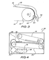
- the machine 80 has similar features to the features hereinbefore disclosed with respect to the machine of Fig 1 .
- the upper belt 82 and lower belt 84 of the machine 80 are of different lengths, such that the downstream ends of both belts 82, 84 are generally aligned vertically, so as to minimize the size of the machine and avoid any wasteful overhang of the upper belt 82 with respect to the lower belt 84. Also, there is no mixer device 50 and no heated retrieval tray 64 in the machine 80, and the dispensing apparatus for the food is located substantially under the lower belt 84, with the dispensing outlet 85 therefor being located substantially over the dispensing platform portion.
- the batter 86 is pumped from a fully enclosed and sealed, cylindrical container 88 of the dispensing apparatus for hygienic and pumping efficiency purposes.
- the vacuum action of a peristaltic pump 90 empties the container 88.
- the hygienic advantage is clear.
- a funnel of air forms between the outlet of the open container and the surface of the batter (like a non spinning vortex). The air sucked into the outlet of such an open container decreases the volume of the batter delivered to the dispensing platform.
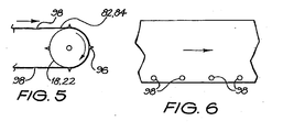
- the belt tracking control and timing arrangement shown in Figs 5 and 6 is provided by means of pins 96 mounted on the diameter edge of the driven rollers 18, 22, the pins 96 engaging within eyelets 98 formed on the belts 82, 84.
- the timing of the belts in this preferred machine is instrumental in its ability to produce high quality pancakes - to eliminate unintentional imprints of the belt joint, and also, to facilitate intentional imprints on the pancake.
- the imprints can be applied on one side, or on both sides, of the pancakes.
- the technique involves altering the thickness of the belt, preferably the lower belt, in the shape of the desired artwork by a small fraction of a millimetre.
- the artwork can be applied by:-
- One way in which the thickness of the belt can be increased is to provide a thin tape/film/foil (possible self-adhesive) or high temperature, durable paint which is affixed/painted to the belt, preferably on the non-cooking side (between the platen and the belt).
- a self-adhesive TEFLON tape (thickness 0.05 - 0.09 mm) is attached underneath the upper run of the lower belt (thickness 0.16 mm).
- the resulting effect is a discoloration of a dual nature. Firstly, the greater heat transferring distance leads to a lighter color of the surface of the pancake in that area. Secondly, the edge of the artwork underneath the upper run of the lower belt creates a small pocket of air. The air, as a poor heat conductor, in effect causes bright silhouette around the artwork.
- One way in which the thickness of the belt can be decreased is by etching or 'engraving' the surface of the belt, preferably the under surface of the belt.
- the upper surface of the belt may also be etched or engraved so long as the exposed surface remains non-stick.
- the embossing of the artwork on the belt is preferably in the direction towards the cooked product.
- the embossed area is directed upwardly towards the pancake laying upon it.
- Fig 9 shows a lower belt 120 in which artwork 122 in the form of a pattern of a smiley face is affixed underneath the top run 124 of the belt and is located between eyelets 126.
- the batter 128 is timed to be deposited upon the top run 124 between the eyelets 126 so that the batter covers the artwork 122.
- the compressive pressure experienced by the pancake causes the artwork to be imprinted upon its underside and the imprinted artwork on the pancake is revealed when the pancake is flipped over.
- the timing can also be used to place an intentional image on the pancake by change of the thickness of the belt(s) within the space designated for the pancake.
- the imprint is not achieved by any additional, non-related operation, as for example, additional print head or stamping device.
- This imprinting feature may be used to imprint promotional materials (ie logos, ads, trademarks, names, news, announcements etc), raising a esthetic appeal, and adding distinctive character for various occasions.
- a sensor switch (not shown) senses one point on the side of the roller in order to pump the mix. Each turn of the roller triggers the dosing of the batter.
- the size of the pancake (determined by the duration of pumping) can be regulated by a simple adjustable cam (not shown).
- the two driven, front rollers are engaged by two geared wheels at the end of the rollers.
Landscapes
- Life Sciences & Earth Sciences (AREA)
- Engineering & Computer Science (AREA)
- Food Science & Technology (AREA)
- Baking, Grill, Roasting (AREA)
- Structure Of Belt Conveyors (AREA)
- Devices For Conveying Motion By Means Of Endless Flexible Members (AREA)
- Cookers (AREA)
- Frying-Pans Or Fryers (AREA)
- General Preparation And Processing Of Foods (AREA)
Claims (8)
- Automatisches Band-Kochgerät (10) zur Herstellung von Nahrungsmittelprodukten, aufweisend obere und untere überlappende, wäremeleitende Bänder (12, 14), die gegenrotierbar an einem Rahmen (16) für die Maschine montiert sind, sodass beim Gebrauch eine untere Förderstrecke (30) des oberen Bandes (12) und eine obere Förderstrecke (32) des unteren Bandes (14) zusammenwirken, um Nahrungsmittel (40) zu fördern, die zwischen dem oberen und dem unteren Band (12, 14) zu den Nahrungsmittelprodukten gegart bzw. gekocht werden sollen, wobei sich das untere Band (14) über einen vorbestimmten Abstand zu einer Seite des oberen Bandes (12) erstreckt, um einen Abgabeplattformabschnitt (38) der oberen Förderstrecke (32) des unteren Bandes (14) zum Abgeben des zu kochenden bzw. garenden Nahrungsmittels darauf bereitzustellen, sodass beim Gebrauch das Nahrungsmittel in eine Richtung zu einer Mündung (52) hin gefördert wird, die zwischen der unteren Förderstrecke (30) des oberen Bandes und der oberen Förderstrecke (32) des unteren Bandes gebildet ist, um das Nahrungsmittel aufzunehmen, und danach das Nahrungsmittel zwischen der unteren Förderstrecke (30) und der oberen Förderstrecke (32) eingefügt zu einem stromabwärtigen Ende des unteren Bandes (14) gefördert wird, an dem Rahmen (16) über und unter der unteren Förderstrecke (30) des oberen Bandes und der oberen Förderstrecke (32) des unteren Bandes befestigte obere bzw. untere Heizplatten (26, 28), wobei das zu garende Nahrungsmittel anfänglich Hitze von der unteren Platte (28) ausgesetzt ist, die zuerst durch den Abgabeplattformabschnitt (38) der oberen Förderstrecke (32) und dann kontinuierlich durch den verbleibenden Abschnitt der oberen Förderstrecke (32) zu der Mündung (52) hin geleitet wird, sodass die Freisetzung von in Blasen eingefangenen Gasen ermöglicht wird, die durch Erhitzen des Nahrungsmittels (40) produziert wurden, bevor das Nahrungsmittel zwischen der unteren Förderstrecke (30) und der oberen Förderstrecke (32) eingefügt wird, und wobei das zu garende Nahrungsmittel (40) dann Hitze von der oberen Platte (26), die durch die obere Förderstrecke (30) geleitet wird sowie von der unteren Platte (28) ausgesetzt ist, die durch die untere Förderstrecke (32) geleitet wird, sodass die Nahrungsmittelprodukte gegart werden, dadurch gekennzeichnet, dass die obere und die untere Heizplatte (26, 28) in Wärmekontakt mit der unteren Förderstrecke (30) des oberen Bandes (12) bzw. der oberen Förderstrecke (32) des unteren Bandes (14) sind, und dass sich die untere Förderstrecke (30) des oberen Bandes (12) und die obere Förderstrecke (32) des unteren Bandes (14) stromaufwärts der Mündung (52) annähern durch die geneigte Montageposition des oberen Bandes (12) in Bezug auf die Montageposition des unteren Bandes (14) und durch die Montagestellen der jeweiligen Platten (26, 28), die gegen ihre jeweiligen Bandförderstrecken (30, 32) drücken, sodass sich eine Klemmwirkung auf das Nahrungsmittelprodukt ergibt, während es auf der oberen Förderstrecke (32) zur Mündung (52) hin und danach zwischen der unteren und der oberen Förderstrecke (30, 32) zu einem stromabwärtigen Ende des unteren Bandes (14) hin gefördert wird.
- Automatisches Band-Kochgerät nach Anspruch 1, das eine Abgabevorrichtung (42) für das Nahrungsmittel mit einem Abgabeauslass (46) aufweist, der über dem Abgabeplattformabschnitt (38) angeordnet ist.
- Automatisches Band-Kochgerät nach Anspruch 1, bei dem die obere Platte (26) schwenkbar zu dem Rahmen (16) montiert ist, sodass eine Einstellung oder Änderung des Abstandes zwischen der unteren und der oberen Platte (26, 28) ermöglicht wird, um unterschiedlichen Dicken oder unterschiedlicher Ausdehung des garenden Nahrungsmittels Platz zu bieten.
- Automatisches Band-Kochgerät nach Anspruch 4, bei dem die obere Platte (27) neben der Mündung (52) schwenkbar (bei 54) montiert ist.
- Automatisches Band-Kochgerät nach Anspruch 4, bei dem die obere Platte (26) einer Drehneigung unterliegt, um einen vorbestimmten Abstand zwischen der oberen und der unteren Platte (26, 28) zu halten, bereitgestellt durch ein Federelement (56).
- Automatisches Band-Kochgerät nach Anspruch 1, das einen unteren Drehstabilisator (60) enthält, der an dem Rahmen neben dem stromabwärtigen Ende des unteren Bandes (14) montiert ist, wobei der Drehstabilisator (60) und das untere Band (14) dazu ausgelegt sind, sich in die gleiche Richtung zu drehen, sodass im Gebrauch die Nahrungsmittelprodukte durch die Drehung des unteren Drehstabilisators (60) von dem unteren Band (14) abgezogen werden.
- Automatisches Band-Kochgerät nach Anspruch 6, das einen oberen Drehstabilisator (63) enthält, der an dem Rahmen (16) neben dem stromabwärtigen Ende des oberen Bandes (12) montiert ist, wobei der obere Drehstabilisator (63) und das obere Band (12) dazu ausgelegt sind, sich in die gleiche Richtung zu drehen, sodass im Gebrauch die Nahrungsmittelprodukte durch die Drehung des oberen Drehstabilisators von dem oberen Band (12) abgezogen werden.
- Automatisches Band-Kochgerät nach Anspruch 1, bei dem das untere Band (120) wenigstens einen Bereich variabler Dicke enthält, der eine auf dem Nahrungsmittel zu druckende Druckvorlage (122) definiert, wenn das Nahrungsmittel zwischen der unteren Förderstrecke (30) und der oberen Förderstrecke (32) eingefügt gefördert wird.
Applications Claiming Priority (3)
| Application Number | Priority Date | Filing Date | Title |
|---|---|---|---|
| AU2002951675 | 2001-11-19 | ||
| AU2002951675A AU2002951675A0 (en) | 2001-11-19 | 2001-11-19 | Automated belt cooking machine for pancakes or the like |
| PCT/AU2002/001563 WO2003043424A1 (en) | 2001-11-19 | 2002-11-19 | Automated belt cooking machine for pancakes or the like |
Publications (3)
| Publication Number | Publication Date |
|---|---|
| EP1494537A1 EP1494537A1 (de) | 2005-01-12 |
| EP1494537A4 EP1494537A4 (de) | 2005-06-01 |
| EP1494537B1 true EP1494537B1 (de) | 2009-11-18 |
Family
ID=3839645
Family Applications (1)
| Application Number | Title | Priority Date | Filing Date |
|---|---|---|---|
| EP02776609A Expired - Lifetime EP1494537B1 (de) | 2001-11-19 | 2002-11-19 | Automatisches band-kochgerät für pfannkuchen oder dergleichen |
Country Status (7)
| Country | Link |
|---|---|
| US (2) | US7325483B2 (de) |
| EP (1) | EP1494537B1 (de) |
| AT (1) | ATE448691T1 (de) |
| AU (3) | AU2002951675A0 (de) |
| DE (1) | DE60234474D1 (de) |
| ES (1) | ES2336085T3 (de) |
| WO (1) | WO2003043424A1 (de) |
Cited By (1)
| Publication number | Priority date | Publication date | Assignee | Title |
|---|---|---|---|---|
| DE102020128147A1 (de) | 2020-10-26 | 2022-04-28 | Olaf Hanses | Injektionsverfahren zum Veredeln von Backwaren, insbesondere von Brot und Brötchen |
Families Citing this family (40)
| Publication number | Priority date | Publication date | Assignee | Title |
|---|---|---|---|---|
| FR2876870B1 (fr) * | 2004-10-21 | 2007-02-23 | Krampouz Soc Par Actions Simpl | Dispositif de distribution d'une dose de pate alimentaire sur une plaque de cuisson, et machine de cuisson equipee d'un tel dispositif |
| WO2006053369A1 (en) * | 2004-11-19 | 2006-05-26 | Tuck-A-Way Engineering & Design Pty. Ltd. | Food preparation apparatus |
| FR2881923A1 (fr) * | 2005-02-15 | 2006-08-18 | Mecatherm Sa | Sole pour four |
| US7987775B2 (en) * | 2005-04-20 | 2011-08-02 | Nottingham-Spirk Design Associates, Inc. | Continuous food cooker |
| US8746132B2 (en) * | 2005-08-12 | 2014-06-10 | Lawrence Equipment Inc. | Heated discharge platen for dough processing system |
| US8555777B2 (en) | 2005-10-04 | 2013-10-15 | Restaurant Technology, Inc. | Two-surface grill with adjustable gap and multi-stage method for cooking food |
| US8692164B2 (en) | 2006-03-13 | 2014-04-08 | Soul Of India, Llc | Cooking appliance |
| US8286548B2 (en) | 2006-03-13 | 2012-10-16 | Soul Of India, Llc | Cooking appliance |
| EP2172108A1 (de) | 2008-10-01 | 2010-04-07 | Mr. Marc Brysse | Verfahren und Gerät für die Massenproduktion von dekorierten Pfannekuchen, Crepes u.ä. und Verbundprodukt daraus |
| US20110206819A1 (en) * | 2008-10-01 | 2011-08-25 | Brysse Marc | Method and apparatus for mass-producing pancakes, crepes, etc |
| US8789459B2 (en) * | 2008-12-05 | 2014-07-29 | Terry Tae-Il Chung | Food heating device |
| US8522673B2 (en) * | 2008-12-05 | 2013-09-03 | Prince Castle, LLC | Food heating device |
| US20100139497A1 (en) * | 2008-12-05 | 2010-06-10 | Prince Castle Inc. | Food heating device |
| JP4990261B2 (ja) * | 2008-12-25 | 2012-08-01 | 日東電工株式会社 | シート部材の接合方法 |
| JP2010200725A (ja) * | 2009-03-06 | 2010-09-16 | Rheon Automatic Machinerty Co Ltd | 食品生地延展装置 |
| US8499683B2 (en) * | 2009-08-08 | 2013-08-06 | Steven Michael Shei | Hot and cold food holding appliance |
| US8757052B2 (en) * | 2009-11-05 | 2014-06-24 | Ebip Holdings, Llc | Conveyor griddle system |
| SI23256A (sl) | 2010-01-21 | 2011-07-29 | Robert ŽERJAL | Postopek neprekinjene toplotne obdelave testa in naprava za izvedbo postopka |
| EP2547210A1 (de) | 2010-03-17 | 2013-01-23 | Marc Brysse | Verfahren für die massenproduktion von dekorierten pfannkuchen, crepes usw. und zusammengesetztes produkt daraus |
| US20120204733A1 (en) * | 2011-02-15 | 2012-08-16 | Gilbert Dennis | Cooking System |
| US8662313B2 (en) | 2011-07-20 | 2014-03-04 | Lawrence Equipment Inc. | Systems and methods for processing comestibles |
| US20140216272A1 (en) * | 2013-02-02 | 2014-08-07 | Leszek Kot | Food cooking apparatus and method |
| EP2872017A4 (de) * | 2012-07-13 | 2016-11-02 | Garland Commercial Ind Llc | Vorrichtung und verfahren zur genauen plattenpositionierung für grills |
| US9775369B2 (en) | 2013-03-12 | 2017-10-03 | Hormel Foods Corporation | Fire braising process for meat |
| WO2015066032A2 (en) * | 2013-10-28 | 2015-05-07 | Enodis Corporation | Vertical broiler |
| USD750422S1 (en) | 2013-11-01 | 2016-03-01 | Nordischer Mashinenbau Rud. Baader GmbH + Co. KG | Machine for preparing food |
| US9687110B2 (en) | 2013-12-04 | 2017-06-27 | Teca Technologies Limited | Pancake maker apparatus, methods and systems |
| USD777816S1 (en) * | 2014-04-29 | 2017-01-31 | Nordischer Maschinenbau Rud. Baader Gmbh + Co. Kg | Machine for preparing food |
| GB2533761B (en) * | 2014-10-10 | 2017-05-03 | Ming Foods Ltd | Oven apparatus and method of baking |
| USD751342S1 (en) | 2015-01-13 | 2016-03-15 | Heartland Food Products, Llc | Pancake forming plates for pancake baker |
| US10194667B2 (en) | 2015-06-26 | 2019-02-05 | Jeffrey F. Klein | Continuous baking system |
| US20170099986A1 (en) * | 2015-10-13 | 2017-04-13 | Dipan Patel | Conveyor-type grilling appliance for cooking or re-thermalizing food |
| CA3004392A1 (en) * | 2015-11-06 | 2017-05-11 | Mukesh Agarwal | Automated preparation of breads |
| CA3015909A1 (en) * | 2016-02-27 | 2017-08-31 | Simplecious Llc | Machines and methods fof making flatbreads |
| US20180289211A1 (en) * | 2016-03-18 | 2018-10-11 | Amanda E. Daniels | Pancake mold |
| US20180116462A1 (en) * | 2016-10-27 | 2018-05-03 | National Presto Industries, Inc. | Method and apparatus for stylizing foodstuff |
| CN107711933A (zh) * | 2017-10-25 | 2018-02-23 | 山东省潍坊市省工食品机械科技有限公司 | 单饼烙制水分蒸发控制装置 |
| US11432554B2 (en) * | 2018-08-03 | 2022-09-06 | National Presto Industries, Inc. | Pancake template and related pancake cooking method |
| CN111742942A (zh) * | 2019-03-28 | 2020-10-09 | 廊坊市盛兴食品机械有限公司 | 一种全自动圆形薄饼机 |
| CN112006045A (zh) * | 2020-09-07 | 2020-12-01 | 珠海城市职业技术学院 | 自动烤地瓜机及其控制方法 |
Family Cites Families (29)
| Publication number | Priority date | Publication date | Assignee | Title |
|---|---|---|---|---|
| US2907450A (en) * | 1957-12-17 | 1959-10-06 | Keelavite Co Ltd | Tensioning mechanism for endless webs |
| US3065079A (en) * | 1958-09-19 | 1962-11-20 | Richard H Williams | Bread treatment method and apparatus therefor |
| US3170564A (en) * | 1963-04-02 | 1965-02-23 | Gatto Charles | Conveyor apparatus |
| US3329561A (en) * | 1964-09-22 | 1967-07-04 | Black Clawson Co | Tension apparatus in the endless forming wire of a fourdrinier paper machine |
| US3528361A (en) * | 1964-11-25 | 1970-09-15 | P Le Van Wayne | Bacon broiling apparatus |
| US3474893A (en) * | 1967-10-06 | 1969-10-28 | Food Equipment Dev Corp | Conveyor |
| US3581652A (en) * | 1967-11-07 | 1971-06-01 | John A Chauvin | Apparatus for processing shrimp |
| US3646880A (en) * | 1970-08-21 | 1972-03-07 | Thermal Process Engineering Co | Cooking grill |
| US3693533A (en) * | 1970-12-28 | 1972-09-26 | Procter & Gamble | Meat analog apparatus |
| US3739712A (en) * | 1971-01-27 | 1973-06-19 | Burger Chef Syst Inc | Apparatus and method for cooking hamburgers or the like |
| US3935322A (en) * | 1973-04-27 | 1976-01-27 | General Mills, Inc. | Chip separating from a fried ribbon |
| US4274331A (en) * | 1974-06-10 | 1981-06-23 | Lang S. Wong | Wafer baking machine |
| US4197792A (en) * | 1977-06-14 | 1980-04-15 | Mendoza Fausto C | Apparatus for molding and precooking corn and wheat tortillas |
| DE3036331A1 (de) * | 1980-09-26 | 1982-05-27 | Claudia 4450 Lingen Falbe | Vorrichtung zum kontinuierlichen braten von nahrungsmitteln |
| US4567819A (en) * | 1985-01-28 | 1986-02-04 | Taylor Freezer Company | Apparatus for two-sided grilling of hamburger patties |
| US4667589A (en) | 1985-10-04 | 1987-05-26 | Bishop Gerald A | Hamburger broiler |
| CA1291370C (en) * | 1986-06-18 | 1991-10-29 | Torahiko Hayashi | Apparatus and method for rolling croissant dough pieces |
| US4882175A (en) * | 1988-05-05 | 1989-11-21 | Wm. Wrigley Jr. Company | Method for forming a confectionary product into a rolled tape |
| US4938126A (en) * | 1988-05-09 | 1990-07-03 | Rubio Manuel J | Tortilla press apparatus |
| US5077072A (en) | 1989-09-19 | 1991-12-31 | Sieradzki Stephan A | Method and apparatus for cooking food on a belt |
| US5088391A (en) * | 1989-11-14 | 1992-02-18 | Anderson Edward M | Method and apparatus for cooking food with a moving belt |
| US5160377A (en) * | 1990-11-14 | 1992-11-03 | Gruma S.A. De C.V. | Apparatus for preventing sticking of stacked food products |
| US5044264A (en) * | 1991-01-28 | 1991-09-03 | Forney Robert B | Cooking apparatus for producing grill stripes on cooked products |
| US5261257A (en) * | 1992-01-30 | 1993-11-16 | Harmony Fastening Systems, Inc. | Separable keyholder with multiple keyrings |
| AU646787B3 (en) | 1993-07-27 | 1994-03-03 | Penny Hlavaty | Cooking arrangements |
| US5458051A (en) * | 1993-11-29 | 1995-10-17 | G. S. Blodgett Corporation | Belt cooking apparatus |
| EP0794724A1 (de) * | 1994-11-30 | 1997-09-17 | Technolizenz Establishment | Röstvorrichtung für röstbare lebensmittel |
| US6026738A (en) * | 1999-09-03 | 2000-02-22 | Doc Machines Works, Inc. | Self-contained crust factory |
| MXPA02007572A (es) * | 2000-02-07 | 2002-12-13 | Recot Inc | Aparato y metodo para hacer trozos alimenticios de refrigerio apilables. |
-
2001
- 2001-11-19 AU AU2002951675A patent/AU2002951675A0/en not_active Abandoned
-
2002
- 2002-11-19 AT AT02776609T patent/ATE448691T1/de not_active IP Right Cessation
- 2002-11-19 ES ES02776609T patent/ES2336085T3/es not_active Expired - Lifetime
- 2002-11-19 AU AU2002339253A patent/AU2002339253B2/en not_active Expired
- 2002-11-19 DE DE60234474T patent/DE60234474D1/de not_active Expired - Lifetime
- 2002-11-19 WO PCT/AU2002/001563 patent/WO2003043424A1/en not_active Ceased
- 2002-11-19 EP EP02776609A patent/EP1494537B1/de not_active Expired - Lifetime
- 2002-11-19 US US10/495,811 patent/US7325483B2/en not_active Expired - Lifetime
-
2007
- 2007-10-31 US US11/980,478 patent/US8151695B2/en not_active Expired - Fee Related
-
2009
- 2009-06-25 AU AU2009202529A patent/AU2009202529B2/en not_active Expired
Cited By (1)
| Publication number | Priority date | Publication date | Assignee | Title |
|---|---|---|---|---|
| DE102020128147A1 (de) | 2020-10-26 | 2022-04-28 | Olaf Hanses | Injektionsverfahren zum Veredeln von Backwaren, insbesondere von Brot und Brötchen |
Also Published As
| Publication number | Publication date |
|---|---|
| EP1494537A4 (de) | 2005-06-01 |
| US20050072311A1 (en) | 2005-04-07 |
| AU2002339253B2 (en) | 2009-05-14 |
| US20080060531A1 (en) | 2008-03-13 |
| WO2003043424A1 (en) | 2003-05-30 |
| ES2336085T3 (es) | 2010-04-08 |
| US8151695B2 (en) | 2012-04-10 |
| AU2009202529B2 (en) | 2012-07-26 |
| EP1494537A1 (de) | 2005-01-12 |
| AU2009202529A1 (en) | 2009-07-16 |
| ATE448691T1 (de) | 2009-12-15 |
| AU2002951675A0 (en) | 2002-10-10 |
| US7325483B2 (en) | 2008-02-05 |
| AU2002339253A1 (en) | 2003-06-10 |
| DE60234474D1 (de) | 2009-12-31 |
Similar Documents
| Publication | Publication Date | Title |
|---|---|---|
| EP1494537B1 (de) | Automatisches band-kochgerät für pfannkuchen oder dergleichen | |
| US5077072A (en) | Method and apparatus for cooking food on a belt | |
| US5996476A (en) | Device for pressing, imprinting and cooking flat bread products | |
| US3718487A (en) | Pancake-making machine | |
| US4517785A (en) | Automatic confectionary-and-likes manufacturing equipment | |
| US6024554A (en) | Dough sheeting apparatus | |
| CA2191336A1 (en) | Process and device for producing rolled wafer cones or the like | |
| US3829593A (en) | Continuous preparation of pastry | |
| US9351496B2 (en) | Production device and production method for layered food | |
| US20070275143A1 (en) | Pie top forming apparatus and method | |
| US3814006A (en) | Machine for manufacturing pancakes and other similar products | |
| KR200207809Y1 (ko) | 종이봉투의 제조장치 | |
| US11896015B1 (en) | Wrapping apparatus for making handheld food | |
| JP3032992B2 (ja) | ロール状加熱・冷却食品の連続製造方法 | |
| US20210169268A1 (en) | Automatic apparatus for the production and cooking of tortillas or similar products | |
| US5558007A (en) | Apparatus for making thin and continuous wrapping sheets | |
| CN2457867Y (zh) | 具有印制装置的春卷皮自动成型机 | |
| JP7776917B1 (ja) | 薄皮状生地シートの製造装置および製造方法 | |
| KR200194676Y1 (ko) | 어묵 생산 기계 | |
| JP3499515B2 (ja) | 煉り食品用自動巻き装置 | |
| AU784398B2 (en) | An oven | |
| JPH071072Y2 (ja) | ロール状加熱・冷却食品の取出装置 | |
| JPS5836351A (ja) | 果肉等の粘性体の注出成型装置 | |
| JPS5923782B2 (ja) | フライ材料にパン粉を付着させる方法および装置 | |
| JPH0787769B2 (ja) | パン粉付着方法及び自動パン粉付機 |
Legal Events
| Date | Code | Title | Description |
|---|---|---|---|
| PUAI | Public reference made under article 153(3) epc to a published international application that has entered the european phase |
Free format text: ORIGINAL CODE: 0009012 |
|
| 17P | Request for examination filed |
Effective date: 20041027 |
|
| AK | Designated contracting states |
Kind code of ref document: A1 Designated state(s): AT BE BG CH CY CZ DE DK EE ES FI FR GB GR IE IT LI LU MC NL PT SE SK TR |
|
| AX | Request for extension of the european patent |
Extension state: AL LT LV MK RO SI |
|
| A4 | Supplementary search report drawn up and despatched |
Effective date: 20050415 |
|
| 17Q | First examination report despatched |
Effective date: 20070326 |
|
| GRAP | Despatch of communication of intention to grant a patent |
Free format text: ORIGINAL CODE: EPIDOSNIGR1 |
|
| GRAS | Grant fee paid |
Free format text: ORIGINAL CODE: EPIDOSNIGR3 |
|
| GRAA | (expected) grant |
Free format text: ORIGINAL CODE: 0009210 |
|
| AK | Designated contracting states |
Kind code of ref document: B1 Designated state(s): AT BE BG CH CY CZ DE DK EE ES FI FR GB GR IE IT LI LU MC NL PT SE SK TR |
|
| REG | Reference to a national code |
Ref country code: GB Ref legal event code: FG4D |
|
| REG | Reference to a national code |
Ref country code: CH Ref legal event code: EP |
|
| REG | Reference to a national code |
Ref country code: IE Ref legal event code: FG4D |
|
| REF | Corresponds to: |
Ref document number: 60234474 Country of ref document: DE Date of ref document: 20091231 Kind code of ref document: P |
|
| REG | Reference to a national code |
Ref country code: SE Ref legal event code: TRGR |
|
| REG | Reference to a national code |
Ref country code: CH Ref legal event code: NV Representative=s name: KIRKER & CIE S.A. |
|
| REG | Reference to a national code |
Ref country code: ES Ref legal event code: FG2A Ref document number: 2336085 Country of ref document: ES Kind code of ref document: T3 |
|
| PG25 | Lapsed in a contracting state [announced via postgrant information from national office to epo] |
Ref country code: FI Free format text: LAPSE BECAUSE OF FAILURE TO SUBMIT A TRANSLATION OF THE DESCRIPTION OR TO PAY THE FEE WITHIN THE PRESCRIBED TIME-LIMIT Effective date: 20091118 Ref country code: PT Free format text: LAPSE BECAUSE OF FAILURE TO SUBMIT A TRANSLATION OF THE DESCRIPTION OR TO PAY THE FEE WITHIN THE PRESCRIBED TIME-LIMIT Effective date: 20100318 |
|
| PG25 | Lapsed in a contracting state [announced via postgrant information from national office to epo] |
Ref country code: CY Free format text: LAPSE BECAUSE OF FAILURE TO SUBMIT A TRANSLATION OF THE DESCRIPTION OR TO PAY THE FEE WITHIN THE PRESCRIBED TIME-LIMIT Effective date: 20091118 |
|
| PG25 | Lapsed in a contracting state [announced via postgrant information from national office to epo] |
Ref country code: MC Free format text: LAPSE BECAUSE OF NON-PAYMENT OF DUE FEES Effective date: 20091130 Ref country code: BE Free format text: LAPSE BECAUSE OF FAILURE TO SUBMIT A TRANSLATION OF THE DESCRIPTION OR TO PAY THE FEE WITHIN THE PRESCRIBED TIME-LIMIT Effective date: 20091118 Ref country code: AT Free format text: LAPSE BECAUSE OF FAILURE TO SUBMIT A TRANSLATION OF THE DESCRIPTION OR TO PAY THE FEE WITHIN THE PRESCRIBED TIME-LIMIT Effective date: 20091118 |
|
| PG25 | Lapsed in a contracting state [announced via postgrant information from national office to epo] |
Ref country code: DK Free format text: LAPSE BECAUSE OF FAILURE TO SUBMIT A TRANSLATION OF THE DESCRIPTION OR TO PAY THE FEE WITHIN THE PRESCRIBED TIME-LIMIT Effective date: 20091118 Ref country code: BG Free format text: LAPSE BECAUSE OF FAILURE TO SUBMIT A TRANSLATION OF THE DESCRIPTION OR TO PAY THE FEE WITHIN THE PRESCRIBED TIME-LIMIT Effective date: 20100218 Ref country code: EE Free format text: LAPSE BECAUSE OF FAILURE TO SUBMIT A TRANSLATION OF THE DESCRIPTION OR TO PAY THE FEE WITHIN THE PRESCRIBED TIME-LIMIT Effective date: 20091118 |
|
| PG25 | Lapsed in a contracting state [announced via postgrant information from national office to epo] |
Ref country code: CZ Free format text: LAPSE BECAUSE OF FAILURE TO SUBMIT A TRANSLATION OF THE DESCRIPTION OR TO PAY THE FEE WITHIN THE PRESCRIBED TIME-LIMIT Effective date: 20091118 Ref country code: SK Free format text: LAPSE BECAUSE OF FAILURE TO SUBMIT A TRANSLATION OF THE DESCRIPTION OR TO PAY THE FEE WITHIN THE PRESCRIBED TIME-LIMIT Effective date: 20091118 |
|
| PLBE | No opposition filed within time limit |
Free format text: ORIGINAL CODE: 0009261 |
|
| STAA | Information on the status of an ep patent application or granted ep patent |
Free format text: STATUS: NO OPPOSITION FILED WITHIN TIME LIMIT |
|
| 26N | No opposition filed |
Effective date: 20100819 |
|
| PG25 | Lapsed in a contracting state [announced via postgrant information from national office to epo] |
Ref country code: IE Free format text: LAPSE BECAUSE OF NON-PAYMENT OF DUE FEES Effective date: 20091119 Ref country code: GR Free format text: LAPSE BECAUSE OF FAILURE TO SUBMIT A TRANSLATION OF THE DESCRIPTION OR TO PAY THE FEE WITHIN THE PRESCRIBED TIME-LIMIT Effective date: 20100219 |
|
| PG25 | Lapsed in a contracting state [announced via postgrant information from national office to epo] |
Ref country code: LU Free format text: LAPSE BECAUSE OF NON-PAYMENT OF DUE FEES Effective date: 20091119 |
|
| REG | Reference to a national code |
Ref country code: FR Ref legal event code: PLFP Year of fee payment: 14 |
|
| REG | Reference to a national code |
Ref country code: FR Ref legal event code: PLFP Year of fee payment: 15 |
|
| REG | Reference to a national code |
Ref country code: FR Ref legal event code: PLFP Year of fee payment: 16 |
|
| PGFP | Annual fee paid to national office [announced via postgrant information from national office to epo] |
Ref country code: NL Payment date: 20211116 Year of fee payment: 20 Ref country code: GB Payment date: 20211116 Year of fee payment: 20 Ref country code: FR Payment date: 20211116 Year of fee payment: 20 Ref country code: ES Payment date: 20211206 Year of fee payment: 20 Ref country code: DE Payment date: 20211116 Year of fee payment: 20 Ref country code: SE Payment date: 20211116 Year of fee payment: 20 Ref country code: TR Payment date: 20211122 Year of fee payment: 20 |
|
| PGFP | Annual fee paid to national office [announced via postgrant information from national office to epo] |
Ref country code: IT Payment date: 20211122 Year of fee payment: 20 Ref country code: CH Payment date: 20211115 Year of fee payment: 20 |
|
| REG | Reference to a national code |
Ref country code: DE Ref legal event code: R071 Ref document number: 60234474 Country of ref document: DE |
|
| REG | Reference to a national code |
Ref country code: NL Ref legal event code: MK Effective date: 20221118 |
|
| REG | Reference to a national code |
Ref country code: CH Ref legal event code: PL |
|
| REG | Reference to a national code |
Ref country code: GB Ref legal event code: PE20 Expiry date: 20221118 |
|
| REG | Reference to a national code |
Ref country code: SE Ref legal event code: EUG |
|
| PG25 | Lapsed in a contracting state [announced via postgrant information from national office to epo] |
Ref country code: GB Free format text: LAPSE BECAUSE OF EXPIRATION OF PROTECTION Effective date: 20221118 |
|
| REG | Reference to a national code |
Ref country code: ES Ref legal event code: FD2A Effective date: 20230503 |
|
| PG25 | Lapsed in a contracting state [announced via postgrant information from national office to epo] |
Ref country code: ES Free format text: LAPSE BECAUSE OF EXPIRATION OF PROTECTION Effective date: 20221120 |