EP1493704A1 - Automatischer Spulenwechsler für einen Parallelspulautomaten - Google Patents
Automatischer Spulenwechsler für einen Parallelspulautomaten Download PDFInfo
- Publication number
- EP1493704A1 EP1493704A1 EP03014811A EP03014811A EP1493704A1 EP 1493704 A1 EP1493704 A1 EP 1493704A1 EP 03014811 A EP03014811 A EP 03014811A EP 03014811 A EP03014811 A EP 03014811A EP 1493704 A1 EP1493704 A1 EP 1493704A1
- Authority
- EP
- European Patent Office
- Prior art keywords
- bobbin
- turntable
- winding station
- changer according
- bobbin changer
- Prior art date
- Legal status (The legal status is an assumption and is not a legal conclusion. Google has not performed a legal analysis and makes no representation as to the accuracy of the status listed.)
- Granted
Links
Images

Classifications
-
- B—PERFORMING OPERATIONS; TRANSPORTING
- B65—CONVEYING; PACKING; STORING; HANDLING THIN OR FILAMENTARY MATERIAL
- B65H—HANDLING THIN OR FILAMENTARY MATERIAL, e.g. SHEETS, WEBS, CABLES
- B65H67/00—Replacing or removing cores, receptacles, or completed packages at paying-out, winding, or depositing stations
- B65H67/04—Arrangements for removing completed take-up packages and or replacing by cores, formers, or empty receptacles at winding or depositing stations; Transferring material between adjacent full and empty take-up elements
- B65H67/044—Continuous winding apparatus for winding on two or more winding heads in succession
- B65H67/048—Continuous winding apparatus for winding on two or more winding heads in succession having winding heads arranged on rotary capstan head
-
- B—PERFORMING OPERATIONS; TRANSPORTING
- B65—CONVEYING; PACKING; STORING; HANDLING THIN OR FILAMENTARY MATERIAL
- B65H—HANDLING THIN OR FILAMENTARY MATERIAL, e.g. SHEETS, WEBS, CABLES
- B65H2701/00—Handled material; Storage means
- B65H2701/30—Handled filamentary material
- B65H2701/31—Textiles threads or artificial strands of filaments
Definitions
- the present invention relates to an automatic bobbin changer for a parallel automatic winder, on which edge disc coils at a winding station of a thread-laying unit bespult be, with the Randusionnspulen placed on a coil recording, transported to the winding station and be gesppult in a vertical position.
- the AP-Winder Hacoba is the bobbin holder is formed by an oblique chute on which the empty bobbins move to the winding station slip and the full bobbins remain until they are removed.
- This system allows no safe replenishment of the empty tubes, as this is strongly influenced by the friction between the coil and slide depends.
- the full bobbins tend to tilt on the sloping chute, and the separation required to avoid damage to the bobbin surface the coils on the winding station can only be realized with considerable mechanical effort become.
- a bobbin changer for a parallel winder be a safe supply of empty bobbins to the winding station and a coil separation made possible by simple means and prevents the tilting of the full bobbins.
- the coil recording by a Turntable is formed, which has separate receiving positions for a plurality of coils and a Having drive for the positioning of bespulenden coil in the winding station.
- the empty bobbins do not slip on a sloping chute but transported by rotation of the turntable to the winding station, wherein the coils already separated by the separate receiving positions of the turntable are and need not be separated anymore.
- a danger of tilting the full spools is no longer because the turntable has no oblique, but a horizontal position.
- a first preferred embodiment of the inventive bobbin changer is characterized in that the turntable at the receiving positions first openings for the passage of the lower part of a provided for fixing the coil in the winding station Coil holder has.
- a second preferred embodiment is characterized in that the drive of the Turntable is formed by an attacking on the periphery of the friction wheel.
- the friction wheel is preferably driven by a stepper motor.
- a third preferred embodiment is characterized by a sensor for detection the rotational position of the turntable.
- This sensor is preferably by a reed contact educated.
- a fourth preferred embodiment of the bobbin changer according to the invention is characterized by a mounted on the turntable centering with on the Recording positions provided second openings or depressions whose Diameter corresponds to the diameter of the edge discs of the coils.
- a fifth preferred embodiment of the bobbin changer according to the invention is characterized by means for locking the turntable in selected rotational positions, which by a provided on the edge of each first opening groove-shaped bulge and formed in this latchable locking pin.
- a further preferred embodiment is characterized in that after completion the winding process by producing a full bobbin in the winding station a rotary motion of the turntable by one pitch to the next recording position.
- the conclusion of the winding process in the winding station by the machine control on the basis of wound yarn length or actual coil diameter calculated.
- a further preferred embodiment is characterized by a full coil sensor for Shut down the machine when there is no empty spool on the turntable.
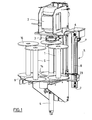
- the winding station shown in Fig. 1 consists essentially of an aluminum profile 1 with a arranged in the region of the upper end of the motor 2 for driving a coil S in the winding process, one consisting of an upper part 3 and a lower part 4 Device for fixing the coil S in the winding station and a laterally on the aluminum profile 1 attached thread laying 5.
- the thread laying 5 is of the in EP-A-1 209 114 described type and includes a yarn guide F, which with a deflection rollers 6, 7th running, flexible, motor driven traversing element 8 is connected and a Traversing movement in the longitudinal direction of the coil S, ie in the vertical direction, executes.
- the Guide roller 6 is as a drive wheel for the drive of the traversing element 8 and the guide roller 7 as a biasing member for the compensation of voltage fluctuations of the traversing element educated.
- EP-A-1 209 114 referenced the disclosure of which is hereby incorporated by reference.
- the winding station is associated with a bobbin changer shown in more detail in FIG essentially has a motor-driven carousel-like turntable 9, which on a rotatable axle 10 is fixed.
- the turntable 9 and the axle 10 and more Components of the bobbin changer are mounted on a plate-like machine mounted on the automatic winder Carousel holder 11 mounted.
- the drive of the turntable is done by one of a Stepper motor 12 driven friction wheel 13 which engages the circumference of the turntable 9.
- Stepping motor 12 is mounted on a motor support 22 connected to the carousel holder 11.
- the turntable 9 has a plurality, as shown four, receiving positions for coils S;
- the centering of the dash-dotted line in Fig. 2 coils at the receiving positions is done by a replaceable at the top of the turntable 9 attached Centering 14, which at the receiving positions depressions or gradations 15th whose diameter corresponds to the diameter of the edge discs 16 of the coil S. and which define the pickup positions.
- Centering 14 which at the receiving positions depressions or gradations 15th whose diameter corresponds to the diameter of the edge discs 16 of the coil S. and which define the pickup positions.
- different centering disks 14 are used, whereby, as can be seen from the figures, Randusionn 16 with a large diameter over the edge of the turntable 9 and the Centering 14 can protrude laterally.
- the depressions 15 of the centering 14th are not complete circles in this case, so that the centering disc 14 is approximately the shape a Maltese cross has.
- the turntable 9 has at each receiving position a first bore 17, which is for the passage of the lower part 4 of the means for fixing the coil S in the winding station provided is.
- Each of the first holes 17 has at the edge of a groove-shaped bulge 18, the is provided for engaging a spring-mounted locking pin 19. Every position of the Turntable 9 is separated by a arranged on the carousel holder 11 sensor 20th detected. This is a reed contact provided by one next to each first bore 17 second bore 21 is actuated.
- the illustrated embodiment of the turntable 9 with four receiving positions is only to be understood as an example, of course, in use provided by coils S with smaller marginal discs 16 and more than four receiving positions be.
- the winding machine recognizes the completion of the winding process on the basis of the wound yarn length, which is measured directly via the delivery mechanism, or on reaching the coil diameter.
- An arranged in the winding station full coil sensor 23 provides the Automatic winder, if there is no empty bobbin on the turntable.
- the motor 2 and the thread laying 5 are stopped coil in question is released from the holding device 3, 4, the locking pin 19 is released and the turntable 9 is further rotated by one pitch. The full spool can now be removed.
- the yarn is at a fixed position clamped and cut and released after starting the engine 2 so that the Beginning to lay under the first layer of yarn.
Landscapes
- Replacing, Conveying, And Pick-Finding For Filamentary Materials (AREA)
- Replacement Of Web Rolls (AREA)
- Spinning Or Twisting Of Yarns (AREA)
Abstract
Description
- Fig. 1
- eine schematische Ansicht der Spulstation und des Spulenwechslers eines Parallelspulautomaten in perspektivischer Darstellung; und
- Fig. 2
- eine Explosionsdarstellung des Spulenwechslers von Fig. 1.
Claims (11)
- Automatischer Spulenwechsler für einen Parallelspulautomaten mit einer Spulstation, an welcher Randscheibenspulen (S) von einem Fadenverlegeaggregat (5) bespult werden, wobei die Randscheibenspulen (S) auf eine Spulenaufnahme aufgesetzt, an die Spulstation transportiert und in vertikaler Lage bespult werden, dadurch gekennzeichnet, dass die Spulenaufnahme durch einen Drehteller (9) gebildet ist, welcher getrennte Aufnahmepositionen für mehrere Spulen (S) und einen Antrieb für die Positionierung der zu bespulenden Spule (S) in der Spulstation aufweist
- Spulenwechsler nach Anspruch 1, dadurch gekennzeichnet, dass der Drehteller (9) an den Aufnahmepositionen erste Durchbrechungen (17) für den Durchgriff des unteren Teils (4) einer zur Fixierung der Spule (S) in der Spulstation vorgesehenen Spulenhalterung aufweist.
- Spulenwechsler nach Anspruch 2, dadurch gekennzeichnet, dass der Antrieb des Drehtellers (9) durch ein an dessen Umfang angreifendes Reibrad (13) gebildet ist.
- Spulenwechsler nach Anspruch 3, dadurch gekennzeichnet, dass das Reibrad (13) durch einen Schrittmotor (12) antreibbar ist.
- Spulenwechsler nach Anspruch 3 oder 4, gekennzeichnet durch einen Sensor zur Erfassung der Drehposition des Drehtellers (9).
- Spulenwechsler nach Anspruch 5, dadurch gekennzeichnet, dass der genannte Sensor durch einen Reedkontakt (20) gebildet ist.
- Spulenwechsler nach einem der Ansprüche 1 bis 6, gekennzeichnet durch eine auf dem Drehteller (9) auswechselbar befestigte Zentrierscheibe (14) mit an den Aufnahmepositionen vorgesehenen zweiten Durchbrechungen (15) oder Vertiefungen, deren Durchmesser dem Durchmesser der Randscheiben (16) der Spulen (S) entspricht.
- Spulenwechsler nach Anspruch 2, gekennzeichnet durch Mittel zur Arretierung des Drehtellers (9) in ausgewählten Drehpositionen, welche durch eine am Rand jeder Durchbrechung (17) vorgesehene rillenförmige Ausbuchtung (18) und einen in diese einrastbaren Arretierstift (19) gebildet sind.
- Spulenwechlser nach einem der Ansprüche 1 bis 8, dadurch gekennzeichnet, dass nach Abschluss des Spulvorgangs durch Herstellung einer vollen Spule (S) in der Spulstation eine Drehbewegung des Drehtellers (9) um eine Teilung bis zur nächsten Aufnahmeposition erfolgt.
- Spulenwechsler nach Anspruch 9, dadurch gekennzeichnet, dass der Abschluss des Spulvorgangs in der Spulstation von der Maschinensteuerung anhand der aufgespulten Garnlänge oder des aktuellen Spulendurchmessers berechnet wird.
- Spulenwechsler nach einem der Ansprüche 1 bis 10, gekennzeichnet durch einen Vollspulensensor (23) für die Abstellung des Spulautomaten, wenn auf dem Drehteller (9) keine leere Spule (S) mehr vorhanden ist.
Priority Applications (4)
| Application Number | Priority Date | Filing Date | Title |
|---|---|---|---|
| DE50309845T DE50309845D1 (de) | 2003-06-30 | 2003-06-30 | Automatischer Spulenwechsler für einen Parallelspulautomaten |
| EP03014811A EP1493704B1 (de) | 2003-06-30 | 2003-06-30 | Automatischer Spulenwechsler für einen Parallelspulautomaten |
| AT03014811T ATE395292T1 (de) | 2003-06-30 | 2003-06-30 | Automatischer spulenwechsler für einen parallelspulautomaten |
| CNB2004100632313A CN100548847C (zh) | 2003-06-30 | 2004-06-30 | 用于平行自动络筒机的自动换筒器 |
Applications Claiming Priority (1)
| Application Number | Priority Date | Filing Date | Title |
|---|---|---|---|
| EP03014811A EP1493704B1 (de) | 2003-06-30 | 2003-06-30 | Automatischer Spulenwechsler für einen Parallelspulautomaten |
Publications (2)
| Publication Number | Publication Date |
|---|---|
| EP1493704A1 true EP1493704A1 (de) | 2005-01-05 |
| EP1493704B1 EP1493704B1 (de) | 2008-05-14 |
Family
ID=33427068
Family Applications (1)
| Application Number | Title | Priority Date | Filing Date |
|---|---|---|---|
| EP03014811A Expired - Lifetime EP1493704B1 (de) | 2003-06-30 | 2003-06-30 | Automatischer Spulenwechsler für einen Parallelspulautomaten |
Country Status (4)
| Country | Link |
|---|---|
| EP (1) | EP1493704B1 (de) |
| CN (1) | CN100548847C (de) |
| AT (1) | ATE395292T1 (de) |
| DE (1) | DE50309845D1 (de) |
Cited By (6)
| Publication number | Priority date | Publication date | Assignee | Title |
|---|---|---|---|---|
| CN106115368A (zh) * | 2016-08-25 | 2016-11-16 | 中天昱品科技有限公司 | 自动单双盘收线装置 |
| CN106414290A (zh) * | 2014-05-08 | 2017-02-15 | 里特机械公司 | 一种纺织机和用于操作这种纺织机的方法 |
| CN110407022A (zh) * | 2019-07-26 | 2019-11-05 | 长飞光纤光缆股份有限公司 | 一种筛选机的自动更换收纤盘装置 |
| CN113060598A (zh) * | 2021-03-26 | 2021-07-02 | 威海宝威新材料科技有限公司 | 一种碳纤维收卷供电装置 |
| CN114083892A (zh) * | 2021-11-12 | 2022-02-25 | 浙江隆生数码纺织科技有限公司 | 一种数码印花机与平网印花机融合过程的精准套印装置 |
| CN117161126A (zh) * | 2023-10-11 | 2023-12-05 | 安徽鑫海高导新材料有限公司 | 一种多头拉丝机的自动换线系统 |
Families Citing this family (10)
| Publication number | Priority date | Publication date | Assignee | Title |
|---|---|---|---|---|
| DE102010035068A1 (de) * | 2010-06-11 | 2011-12-15 | Oerlikon Textile Gmbh & Co. Kg | Kreuzspulen herstellende Textilmaschine mit einem verfahrbaren Wanderaggregat zum Einsetzen einer Leerhülse |
| DE102011003048B4 (de) * | 2011-01-24 | 2017-11-23 | Rieter Ingolstadt Gmbh | Mehrkopfstrecke und Verfahren zum Wechseln von Kannen an einer Mehrkopfstrecke |
| DE102011075632A1 (de) * | 2011-05-11 | 2012-11-15 | Rieter Ingolstadt Gmbh | Kannenwechsler für eine Spinnereivorbereitungsmaschine sowie Verfahren zum Kannenwechsel |
| CN103366896A (zh) * | 2013-07-05 | 2013-10-23 | 苏州圣利线缆有限公司 | 自动化漆包线下线装置 |
| JP2016108086A (ja) * | 2014-12-05 | 2016-06-20 | 村田機械株式会社 | 糸巻取機 |
| CN110642096A (zh) * | 2019-09-19 | 2020-01-03 | 苏州济洋纺织机械有限公司 | 一种络筒机用换筒机构 |
| CN111547581A (zh) * | 2020-05-28 | 2020-08-18 | 王玮 | 一种用于络筒机的筒子架结构 |
| CN115028020B (zh) * | 2022-07-22 | 2024-04-16 | 浙江理工大学 | 一种适用于不同型号管纱及储管纱圆盘的智能装填机械臂 |
| CN117963637B (zh) * | 2024-03-12 | 2025-10-28 | 杭州聚乾实业有限公司 | 一种混纺纱线的制备系统及纺纱工艺 |
| CN119038327A (zh) * | 2024-11-01 | 2024-11-29 | 启东市万隆电气光源有限公司 | 一种柔性led灯丝生产的自动绕卷机 |
Citations (3)
| Publication number | Priority date | Publication date | Assignee | Title |
|---|---|---|---|---|
| GB524528A (en) * | 1938-03-22 | 1940-08-08 | Vetreria Italiana Balz | Improvements in or relating to the manufacture of threads of glass or other synthetic material |
| FR1117576A (fr) * | 1954-12-27 | 1956-05-24 | Telecommunications Sa | Enrouloir continu automatique |
| US3559902A (en) * | 1967-09-05 | 1971-02-02 | Ici Ltd | Continuous winding of yarns |
-
2003
- 2003-06-30 DE DE50309845T patent/DE50309845D1/de not_active Expired - Lifetime
- 2003-06-30 EP EP03014811A patent/EP1493704B1/de not_active Expired - Lifetime
- 2003-06-30 AT AT03014811T patent/ATE395292T1/de not_active IP Right Cessation
-
2004
- 2004-06-30 CN CNB2004100632313A patent/CN100548847C/zh not_active Expired - Fee Related
Patent Citations (3)
| Publication number | Priority date | Publication date | Assignee | Title |
|---|---|---|---|---|
| GB524528A (en) * | 1938-03-22 | 1940-08-08 | Vetreria Italiana Balz | Improvements in or relating to the manufacture of threads of glass or other synthetic material |
| FR1117576A (fr) * | 1954-12-27 | 1956-05-24 | Telecommunications Sa | Enrouloir continu automatique |
| US3559902A (en) * | 1967-09-05 | 1971-02-02 | Ici Ltd | Continuous winding of yarns |
Cited By (8)
| Publication number | Priority date | Publication date | Assignee | Title |
|---|---|---|---|---|
| CN106414290A (zh) * | 2014-05-08 | 2017-02-15 | 里特机械公司 | 一种纺织机和用于操作这种纺织机的方法 |
| CN106115368A (zh) * | 2016-08-25 | 2016-11-16 | 中天昱品科技有限公司 | 自动单双盘收线装置 |
| CN106115368B (zh) * | 2016-08-25 | 2018-12-14 | 中天智能装备有限公司 | 自动单双盘收线装置 |
| CN110407022A (zh) * | 2019-07-26 | 2019-11-05 | 长飞光纤光缆股份有限公司 | 一种筛选机的自动更换收纤盘装置 |
| CN113060598A (zh) * | 2021-03-26 | 2021-07-02 | 威海宝威新材料科技有限公司 | 一种碳纤维收卷供电装置 |
| CN114083892A (zh) * | 2021-11-12 | 2022-02-25 | 浙江隆生数码纺织科技有限公司 | 一种数码印花机与平网印花机融合过程的精准套印装置 |
| CN114083892B (zh) * | 2021-11-12 | 2023-10-27 | 浙江隆生数码纺织科技有限公司 | 一种数码印花机与平网印花机融合过程的精准套印装置 |
| CN117161126A (zh) * | 2023-10-11 | 2023-12-05 | 安徽鑫海高导新材料有限公司 | 一种多头拉丝机的自动换线系统 |
Also Published As
| Publication number | Publication date |
|---|---|
| ATE395292T1 (de) | 2008-05-15 |
| EP1493704B1 (de) | 2008-05-14 |
| CN100548847C (zh) | 2009-10-14 |
| DE50309845D1 (de) | 2008-06-26 |
| CN1576219A (zh) | 2005-02-09 |
Similar Documents
| Publication | Publication Date | Title |
|---|---|---|
| EP1493704B1 (de) | Automatischer Spulenwechsler für einen Parallelspulautomaten | |
| DE102014220875A1 (de) | Wickelmaschine für gesponnenes Garn | |
| DE3128538A1 (de) | "schaeranlage" | |
| DE102008026777A1 (de) | Saugdüse | |
| DE69806795T2 (de) | Wickler für synthetische filamente | |
| DE2402238A1 (de) | Maschine zur herstellung von chenille | |
| EP1496003B1 (de) | Automatischer Spulenwechsler für einen Parallelspulautomaten | |
| DE69822592T2 (de) | Aufwickelvorrichtung insbesondere für Garn | |
| DE2710821C3 (de) | Fadenliefervorrichtung für Textilmaschinen | |
| DE102006004894B4 (de) | Hilfsfadenführer zum Changieren eines laufenden Fadens im Bereich einer Fadenabzugseinrichtung einer Kreuzspulen herstellenden Textilmaschine | |
| AT401395B (de) | Vorrichtung zum reinigen von unterwindeflächen an spindeln von ringspinn- oder ringzwirnmaschinen | |
| DE3344993A1 (de) | Mehrstellige textilmaschine | |
| CH663200A5 (de) | Verfahren zum erzeugen oder bearbeiten und aufwickeln von faeden. | |
| EP2122024B1 (de) | Vorrichtung zum positionieren der fäden innerhalb der bandbreite eines schärbandes und schärverfahren | |
| DE2643434B2 (de) | Spulenwechselvorrichtung | |
| DE3018104C2 (de) | Spulenwechsler für Fachzwirnmaschinen | |
| DE102005050369A1 (de) | Dreh-Garnliefervorrichtung mit Garndurchgangssteuerführern und Musterschärer, der Garndurchgangssteuerführer aufweist | |
| DE928513C (de) | Kreuzspulmaschine | |
| DE19854817A1 (de) | Einzelspindler zum Umspulen von Kopsen zu Kreuzspulen | |
| DE2257944C2 (de) | Vorrichtung zum fortlaufenden Aufwickeln von fadenförmigem Gut | |
| DE2123979A1 (de) | Aufspul vorrichtung | |
| DE2642997A1 (de) | Speichervorrichtung fuer papierrollen | |
| DE268245C (de) | ||
| DE69016203T2 (de) | Vorrichtung zum Aufnehmen und Zuführen in einem vorbestimmten Weg eines auf einer Spule aufgewickelten Magnetbandes in einem automatischen Kassettenladegerät. | |
| DE2120814C3 (de) | Vorrichtung zum Füllen der Schützen von Wellenfach-Webmaschinen |
Legal Events
| Date | Code | Title | Description |
|---|---|---|---|
| PUAI | Public reference made under article 153(3) epc to a published international application that has entered the european phase |
Free format text: ORIGINAL CODE: 0009012 |
|
| 17P | Request for examination filed |
Effective date: 20040408 |
|
| AK | Designated contracting states |
Kind code of ref document: A1 Designated state(s): AT BE BG CH CY CZ DE DK EE ES FI FR GB GR HU IE IT LI LU MC NL PT RO SE SI SK TR |
|
| AX | Request for extension of the european patent |
Extension state: AL LT LV MK |
|
| AKX | Designation fees paid |
Designated state(s): AT BE BG CH CY CZ DE DK EE ES FI FR GB GR HU IE IT LI LU MC NL PT RO SE SI SK TR |
|
| 17Q | First examination report despatched |
Effective date: 20061109 |
|
| GRAP | Despatch of communication of intention to grant a patent |
Free format text: ORIGINAL CODE: EPIDOSNIGR1 |
|
| GRAS | Grant fee paid |
Free format text: ORIGINAL CODE: EPIDOSNIGR3 |
|
| GRAA | (expected) grant |
Free format text: ORIGINAL CODE: 0009210 |
|
| RAP1 | Party data changed (applicant data changed or rights of an application transferred) |
Owner name: SSM SCHAERER SCHWEITER METTLER AG |
|
| AK | Designated contracting states |
Kind code of ref document: B1 Designated state(s): AT BE BG CH CY CZ DE DK EE ES FI FR GB GR HU IE IT LI LU MC NL PT RO SE SI SK TR |
|
| REG | Reference to a national code |
Ref country code: GB Ref legal event code: FG4D Free format text: NOT ENGLISH |
|
| REG | Reference to a national code |
Ref country code: CH Ref legal event code: NV Representative=s name: RIEDERER HASLER & PARTNER PATENTANWAELTE AG Ref country code: CH Ref legal event code: EP |
|
| REG | Reference to a national code |
Ref country code: IE Ref legal event code: FG4D Free format text: LANGUAGE OF EP DOCUMENT: GERMAN |
|
| REF | Corresponds to: |
Ref document number: 50309845 Country of ref document: DE Date of ref document: 20080626 Kind code of ref document: P |
|
| PG25 | Lapsed in a contracting state [announced via postgrant information from national office to epo] |
Ref country code: SI Free format text: LAPSE BECAUSE OF FAILURE TO SUBMIT A TRANSLATION OF THE DESCRIPTION OR TO PAY THE FEE WITHIN THE PRESCRIBED TIME-LIMIT Effective date: 20080514 |
|
| PG25 | Lapsed in a contracting state [announced via postgrant information from national office to epo] |
Ref country code: FI Free format text: LAPSE BECAUSE OF FAILURE TO SUBMIT A TRANSLATION OF THE DESCRIPTION OR TO PAY THE FEE WITHIN THE PRESCRIBED TIME-LIMIT Effective date: 20080514 Ref country code: ES Free format text: LAPSE BECAUSE OF FAILURE TO SUBMIT A TRANSLATION OF THE DESCRIPTION OR TO PAY THE FEE WITHIN THE PRESCRIBED TIME-LIMIT Effective date: 20080825 |
|
| NLV1 | Nl: lapsed or annulled due to failure to fulfill the requirements of art. 29p and 29m of the patents act | ||
| PG25 | Lapsed in a contracting state [announced via postgrant information from national office to epo] |
Ref country code: NL Free format text: LAPSE BECAUSE OF FAILURE TO SUBMIT A TRANSLATION OF THE DESCRIPTION OR TO PAY THE FEE WITHIN THE PRESCRIBED TIME-LIMIT Effective date: 20080514 |
|
| BERE | Be: lapsed |
Owner name: SSM SCHARER SCHWEITER METTLER A.G. Effective date: 20080630 |
|
| REG | Reference to a national code |
Ref country code: IE Ref legal event code: FD4D |
|
| PG25 | Lapsed in a contracting state [announced via postgrant information from national office to epo] |
Ref country code: CZ Free format text: LAPSE BECAUSE OF FAILURE TO SUBMIT A TRANSLATION OF THE DESCRIPTION OR TO PAY THE FEE WITHIN THE PRESCRIBED TIME-LIMIT Effective date: 20080514 Ref country code: SE Free format text: LAPSE BECAUSE OF FAILURE TO SUBMIT A TRANSLATION OF THE DESCRIPTION OR TO PAY THE FEE WITHIN THE PRESCRIBED TIME-LIMIT Effective date: 20080814 Ref country code: IE Free format text: LAPSE BECAUSE OF FAILURE TO SUBMIT A TRANSLATION OF THE DESCRIPTION OR TO PAY THE FEE WITHIN THE PRESCRIBED TIME-LIMIT Effective date: 20080514 Ref country code: MC Free format text: LAPSE BECAUSE OF NON-PAYMENT OF DUE FEES Effective date: 20080630 Ref country code: DK Free format text: LAPSE BECAUSE OF FAILURE TO SUBMIT A TRANSLATION OF THE DESCRIPTION OR TO PAY THE FEE WITHIN THE PRESCRIBED TIME-LIMIT Effective date: 20080514 Ref country code: PT Free format text: LAPSE BECAUSE OF FAILURE TO SUBMIT A TRANSLATION OF THE DESCRIPTION OR TO PAY THE FEE WITHIN THE PRESCRIBED TIME-LIMIT Effective date: 20081014 |
|
| PG25 | Lapsed in a contracting state [announced via postgrant information from national office to epo] |
Ref country code: SK Free format text: LAPSE BECAUSE OF FAILURE TO SUBMIT A TRANSLATION OF THE DESCRIPTION OR TO PAY THE FEE WITHIN THE PRESCRIBED TIME-LIMIT Effective date: 20080514 Ref country code: RO Free format text: LAPSE BECAUSE OF FAILURE TO SUBMIT A TRANSLATION OF THE DESCRIPTION OR TO PAY THE FEE WITHIN THE PRESCRIBED TIME-LIMIT Effective date: 20080514 |
|
| PLBE | No opposition filed within time limit |
Free format text: ORIGINAL CODE: 0009261 |
|
| STAA | Information on the status of an ep patent application or granted ep patent |
Free format text: STATUS: NO OPPOSITION FILED WITHIN TIME LIMIT |
|
| PG25 | Lapsed in a contracting state [announced via postgrant information from national office to epo] |
Ref country code: BE Free format text: LAPSE BECAUSE OF NON-PAYMENT OF DUE FEES Effective date: 20080630 |
|
| 26N | No opposition filed |
Effective date: 20090217 |
|
| GBPC | Gb: european patent ceased through non-payment of renewal fee |
Effective date: 20080814 |
|
| PG25 | Lapsed in a contracting state [announced via postgrant information from national office to epo] |
Ref country code: BG Free format text: LAPSE BECAUSE OF FAILURE TO SUBMIT A TRANSLATION OF THE DESCRIPTION OR TO PAY THE FEE WITHIN THE PRESCRIBED TIME-LIMIT Effective date: 20080814 Ref country code: EE Free format text: LAPSE BECAUSE OF FAILURE TO SUBMIT A TRANSLATION OF THE DESCRIPTION OR TO PAY THE FEE WITHIN THE PRESCRIBED TIME-LIMIT Effective date: 20080514 |
|
| PG25 | Lapsed in a contracting state [announced via postgrant information from national office to epo] |
Ref country code: AT Free format text: LAPSE BECAUSE OF NON-PAYMENT OF DUE FEES Effective date: 20080630 |
|
| PGFP | Annual fee paid to national office [announced via postgrant information from national office to epo] |
Ref country code: CH Payment date: 20090617 Year of fee payment: 7 |
|
| PG25 | Lapsed in a contracting state [announced via postgrant information from national office to epo] |
Ref country code: GB Free format text: LAPSE BECAUSE OF NON-PAYMENT OF DUE FEES Effective date: 20080814 |
|
| PG25 | Lapsed in a contracting state [announced via postgrant information from national office to epo] |
Ref country code: HU Free format text: LAPSE BECAUSE OF FAILURE TO SUBMIT A TRANSLATION OF THE DESCRIPTION OR TO PAY THE FEE WITHIN THE PRESCRIBED TIME-LIMIT Effective date: 20081115 Ref country code: LU Free format text: LAPSE BECAUSE OF NON-PAYMENT OF DUE FEES Effective date: 20080630 Ref country code: CY Free format text: LAPSE BECAUSE OF FAILURE TO SUBMIT A TRANSLATION OF THE DESCRIPTION OR TO PAY THE FEE WITHIN THE PRESCRIBED TIME-LIMIT Effective date: 20080514 |
|
| PG25 | Lapsed in a contracting state [announced via postgrant information from national office to epo] |
Ref country code: GR Free format text: LAPSE BECAUSE OF FAILURE TO SUBMIT A TRANSLATION OF THE DESCRIPTION OR TO PAY THE FEE WITHIN THE PRESCRIBED TIME-LIMIT Effective date: 20080815 |
|
| REG | Reference to a national code |
Ref country code: CH Ref legal event code: PL |
|
| PG25 | Lapsed in a contracting state [announced via postgrant information from national office to epo] |
Ref country code: CH Free format text: LAPSE BECAUSE OF NON-PAYMENT OF DUE FEES Effective date: 20100630 Ref country code: LI Free format text: LAPSE BECAUSE OF NON-PAYMENT OF DUE FEES Effective date: 20100630 |
|
| PGFP | Annual fee paid to national office [announced via postgrant information from national office to epo] |
Ref country code: TR Payment date: 20110627 Year of fee payment: 9 |
|
| REG | Reference to a national code |
Ref country code: FR Ref legal event code: ST Effective date: 20110708 |
|
| PG25 | Lapsed in a contracting state [announced via postgrant information from national office to epo] |
Ref country code: FR Free format text: LAPSE BECAUSE OF NON-PAYMENT OF DUE FEES Effective date: 20080715 |
|
| PGFP | Annual fee paid to national office [announced via postgrant information from national office to epo] |
Ref country code: DE Payment date: 20110727 Year of fee payment: 9 |
|
| PGFP | Annual fee paid to national office [announced via postgrant information from national office to epo] |
Ref country code: IT Payment date: 20110630 Year of fee payment: 9 |
|
| PG25 | Lapsed in a contracting state [announced via postgrant information from national office to epo] |
Ref country code: IT Free format text: LAPSE BECAUSE OF NON-PAYMENT OF DUE FEES Effective date: 20120630 |
|
| REG | Reference to a national code |
Ref country code: DE Ref legal event code: R119 Ref document number: 50309845 Country of ref document: DE Effective date: 20130101 |
|
| PG25 | Lapsed in a contracting state [announced via postgrant information from national office to epo] |
Ref country code: DE Free format text: LAPSE BECAUSE OF NON-PAYMENT OF DUE FEES Effective date: 20130101 |
|
| PG25 | Lapsed in a contracting state [announced via postgrant information from national office to epo] |
Ref country code: TR Free format text: LAPSE BECAUSE OF NON-PAYMENT OF DUE FEES Effective date: 20120630 |