EP1493524A2 - Einrichtung zum Benetzen von Kabelenden - Google Patents
Einrichtung zum Benetzen von Kabelenden Download PDFInfo
- Publication number
- EP1493524A2 EP1493524A2 EP04014383A EP04014383A EP1493524A2 EP 1493524 A2 EP1493524 A2 EP 1493524A2 EP 04014383 A EP04014383 A EP 04014383A EP 04014383 A EP04014383 A EP 04014383A EP 1493524 A2 EP1493524 A2 EP 1493524A2
- Authority
- EP
- European Patent Office
- Prior art keywords
- wetting agent
- nozzle
- bath
- wetting
- conveyor unit
- Prior art date
- Legal status (The legal status is an assumption and is not a legal conclusion. Google has not performed a legal analysis and makes no representation as to the accuracy of the status listed.)
- Granted
Links
Images

Classifications
-
- B—PERFORMING OPERATIONS; TRANSPORTING
- B23—MACHINE TOOLS; METAL-WORKING NOT OTHERWISE PROVIDED FOR
- B23K—SOLDERING OR UNSOLDERING; WELDING; CLADDING OR PLATING BY SOLDERING OR WELDING; CUTTING BY APPLYING HEAT LOCALLY, e.g. FLAME CUTTING; WORKING BY LASER BEAM
- B23K3/00—Tools, devices or special appurtenances for soldering, e.g. brazing, or unsoldering, not specially adapted for particular methods
- B23K3/06—Solder feeding devices; Solder melting pans
Definitions
- the invention relates to a device for wetting Cable ends, consisting of one on a stand arranged conveyor unit and from a bath tank with Wetting agent, wherein the conveyor unit in the Bath container in stock wetting agent for Cable end promotes.
- a disadvantage of the known device is that the shaft is firmly connected to the bath tank. The Cleaning the Zinnbadober Assembly or the bathroom mirror is makes it difficult.
- the invention aims to remedy this situation.
- the invention as characterized in claim 1 solves the task to avoid the disadvantages of the known device and to provide a device for wetting cable ends, which is easy to handle.
- the advantages achieved by the invention are in essential to see that for the promotion of the Means for wetting the cable ends necessary parts easy to install or expand.
- Delivery pipe, pump Nozzle and actuator form a unit that is tool-free in the bath container can be used or removed. Moreover is the excess wetting agent laterally at the Discharged nozzle and returned to the bath. The nozzle can thereby arranged closer to the front wall of the bath tank , resulting in shorter cable lengths to the wetting process can be subjected.
- To heat up the bath and Holding the bath temperature is the bath container usually provided with a floor heating. The bathroom is from below heated up, which has the consequence that at the Bad surface can form explosive splashes. With the inventive device, the surprisingly occurring splashes are avoided.
- To the bath container has at least one inclined, heatable Wall rising from the tank bottom.
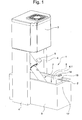
- Fig. 1 shows an inventive device 1 for Wetting cable ends 2.
- the device 1 consists of a controller 3 supporting stand 4, a Badbeälter 5 with a bath 6 and a conveyor unit. 7 for promoting a bath 6 forming wetting agent to the cable end 2. With 6.1 the bath level is designated.
- Wetting agent for example, solder (with or without Lead). The use of others Wetting agent is also conceivable.
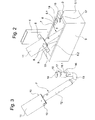
- Fig. 2 shows the bath tank 5 and the conveyor unit 7 for Conveying the wetting agent.
- the conveyor unit 7 is supported by the stand 4 arranged carriers 8.
- Per carrier 8 a V-shaped recess 9 is provided, into which a Support pin 10 of the conveyor unit 7 fits.
- FIG. 3 shows the conveyor unit 7 consisting of drive 11, Pump unit 12, delivery pipe 13 and nozzle 14 with aperture 15.
- the conveyor unit 7 is mounted on the two support pins 10 and on an angular support 16 with a circular recess 16.1.
- the edition 16 is at the Inside the front wall 5.1 of the bath tank 5 is arranged and positions the nozzle 14 centered and in height.
- the support pins 10 and by means of Edition 16 is the conveyor unit 7 without tools in the Bath tank 5 can be used or removed.
- the 4 shows a longitudinal section through the conveyor unit 7 and the bath tank 5.
- the bath tank 5 is provided with a provided obliquely sloping rear wall 5.2, the heated is.
- the bath 6 is not only from bottom to top heated but at least partially at the Surface.
- At least one side wall of the bath container 5 can also be heated and sloping sloping.
- the pump unit 12 is provided with an inlet opening 12.1 provided by the wetting agent to a pump 12.2 arrives.
- the impeller 12.2 is by means of a shaft 12.3 driven, thermally insulated (clutch 12.4) is connected to a drive motor 11.1.
- the impeller 12.2 conveys the wetting agent through the delivery pipe 13 to the nozzle 14, wherein the wetting agent by drilling 14.1 to the replaceable panel 15 flows, the shape and Size of the free jet of wetting agent determined.
- the stripped cable end 2.1 is in the free beam of the Wetting agent brought, wherein the cable ladder or the Cable strands are heated by the wetting agent and the wetting agent the cable conductor or cable strands wetted or penetrates into the cable strands.
- solder as a wetting agent is the for example, made of copper cable ladder or the for example, made of copper tinned strands.
- the Excess wetting agent flows laterally of the nozzle 14 back and forth in the bath tank 5.
- the supply of stripped cable ends 2.1 can be manual or automatic done by means of grippers.
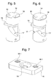
- FIG. 5 and Fig. 6 show details of the nozzle 14, wherein 5 shows a nozzle 14 with a lateral outlet 17 and FIG. 6 show a nozzle with two lateral outlets 17.
- Of the Process 17 is created by a section in the cylindrical nozzle 14 below the aperture 15.
- the cable end 2 with a pivoting movement of the free beam of Wetting agent are supplied.
- Fig. 7 shows details of the aperture 15, which means Screws 18 is releasably connected to the nozzle 14, wherein the screws 18 in threaded holes 18.1 of the aperture 15th fit.
- the aperture 15 is provided with a bore 19, through which the wetting agent flows. Size and shape of the Bore may vary depending on the desired free jet.
Landscapes
- Engineering & Computer Science (AREA)
- Mechanical Engineering (AREA)
- Molten Solder (AREA)
- Application Of Or Painting With Fluid Materials (AREA)
- Coating Apparatus (AREA)
- Electric Connection Of Electric Components To Printed Circuits (AREA)
- Manufacturing Of Electrical Connectors (AREA)
Abstract
Description
eine erfindungsgemässe Einrichtung zum Benetzen von Kabelenden,
einen Badbehälter und eine Fördereinheit zum Fördern eines Benetzungsmittels,
die Fördereinheit,
einen Schnitt durch die Fördereinheit und den Badbehälter,
Einzelheiten einer Düse der Fördereinheit und
Einzelheiten einer Blende der Düse.
Claims (6)
- Einrichtung (1) zum Benetzen von Kabelenden (2), bestehend aus einer an einem Ständer (4) angeordneten Fördereinheit (7) und aus einem Badbehälter (5) mit Benetzungsmittel, wobei die Fördereinheit (7) das im Badbehälter (5) vorrätig gehaltene Benetzungsmittel zum Kabelende (2) fördert,
dadurch gekennzeichnet, dass die Fördereinheit (7) werkzeuglos in den Badbehälter (5) einsetzbar bzw. entfernbar ist. - Einrichtung nach Anspruch 1,
dadurch gekennzeichnet, dass die Fördereinheit (7) von am Ständer (4) angeordneten Trägern (8) und von einer an einer Frontwand (5.1) des Badbehälters (5) angeordneten Auflage (16) getragen wird, wobei Stützstifte (10) der Fördereinheit (7) in Aussparungen (9) der Träger (8) gehalten werden. - Einrichtung nach einem der Ansprüche 1 oder 2,
dadurch gekennzeichnet, dass die Fördereinheit (7) einen Antrieb (11), eine Pumpeneinheit (12), ein Förderrohr (13) und eine Düse (14) aufweist, wobei ein Pumpenrad (12.2) das Benetzungsmittel vom Badbehälter (5) über das Förderrohr (13) zur Düse (14) fördert. - Einrichtung nach Anspruch 3,
dadurch gekennzeichnet, dass die Düse (14) mit einer auswechselbaren Blende (15) versehen ist, deren Bohrung (19) die Form und Grösse des freien Strahls des Benetzungsmittels bestimmt. - Einrichtung nach Anspruch 4,
dadurch gekennzeichnet, dass die Düse (14) mindestens einen seitlichen Ablauf (17) aufweist, über den das überschüssige Benetzungsmittel abfliesst. - Einrichtung nach einem der vorhergehenden Ansprüche,
dadurch gekennzeichnet, dass der Badbehälter (5) mindestens eine schräg abfallende, beheizbare Wand (5.2) aufweist.
Priority Applications (1)
| Application Number | Priority Date | Filing Date | Title |
|---|---|---|---|
| EP20040014383 EP1493524B1 (de) | 2003-07-03 | 2004-06-17 | Einrichtung zum Benetzen von Kabelenden |
Applications Claiming Priority (3)
| Application Number | Priority Date | Filing Date | Title |
|---|---|---|---|
| EP03405496 | 2003-07-03 | ||
| EP03405496 | 2003-07-03 | ||
| EP20040014383 EP1493524B1 (de) | 2003-07-03 | 2004-06-17 | Einrichtung zum Benetzen von Kabelenden |
Publications (3)
| Publication Number | Publication Date |
|---|---|
| EP1493524A2 true EP1493524A2 (de) | 2005-01-05 |
| EP1493524A3 EP1493524A3 (de) | 2006-05-17 |
| EP1493524B1 EP1493524B1 (de) | 2008-11-05 |
Family
ID=33436139
Family Applications (1)
| Application Number | Title | Priority Date | Filing Date |
|---|---|---|---|
| EP20040014383 Expired - Lifetime EP1493524B1 (de) | 2003-07-03 | 2004-06-17 | Einrichtung zum Benetzen von Kabelenden |
Country Status (1)
| Country | Link |
|---|---|
| EP (1) | EP1493524B1 (de) |
Cited By (1)
| Publication number | Priority date | Publication date | Assignee | Title |
|---|---|---|---|---|
| CN113002371A (zh) * | 2019-12-19 | 2021-06-22 | 中国铁建电气化局集团有限公司 | 一种吊弦预配方法 |
Family Cites Families (4)
| Publication number | Priority date | Publication date | Assignee | Title |
|---|---|---|---|---|
| US3765591A (en) * | 1972-01-19 | 1973-10-16 | Dynamics Corp America | Wave soldering electrical connections |
| US4011980A (en) * | 1976-03-25 | 1977-03-15 | Western Electric Company, Inc. | Flow-over mass soldering |
| DE2844236C2 (de) * | 1978-10-11 | 1982-12-09 | Dietrich 3420 Herzberg Reidt | Vorrichtung zum Verzinnen von Drahtenden, insbesondere abisolierten Kabelenden |
| DE3650049T2 (de) * | 1985-07-10 | 1995-03-30 | Evenoak Ltd | Lötverfahren. |
-
2004
- 2004-06-17 EP EP20040014383 patent/EP1493524B1/de not_active Expired - Lifetime
Cited By (1)
| Publication number | Priority date | Publication date | Assignee | Title |
|---|---|---|---|---|
| CN113002371A (zh) * | 2019-12-19 | 2021-06-22 | 中国铁建电气化局集团有限公司 | 一种吊弦预配方法 |
Also Published As
| Publication number | Publication date |
|---|---|
| EP1493524A3 (de) | 2006-05-17 |
| EP1493524B1 (de) | 2008-11-05 |
Similar Documents
| Publication | Publication Date | Title |
|---|---|---|
| DE112011100931T5 (de) | Lötrückführung für Wellenlötdüse | |
| CH662310A5 (de) | Buchbindemaschine. | |
| EP0090233A1 (de) | Vorrichtung zur Reinigung eines Schweissbrenners | |
| EP0010786B1 (de) | Anode für die elektrolytische Gewinnung oder galvanische Abscheidung von Nicht-Eisen-Metallen | |
| DE1573974B2 (de) | Vorrichtung zum aufeinanderfolgenden Behandeln von auf einem Objektträger angebrachten Objekten | |
| DE2619342C3 (de) | Wellenlötvorrichtung | |
| WO2004110681A1 (de) | Vorrichtung zum beschicken von giesseinrichtungen mit metallschmelze | |
| EP1493524B1 (de) | Einrichtung zum Benetzen von Kabelenden | |
| DE3650049T2 (de) | Lötverfahren. | |
| DE1807989C3 (de) | Vorrichtung zur Lötung elektrischer Verbindungen, insbesondere gedruckter Schaltungen | |
| US7685964B2 (en) | Device for wetting cable-ends | |
| DE2844236C2 (de) | Vorrichtung zum Verzinnen von Drahtenden, insbesondere abisolierten Kabelenden | |
| DE8712698U1 (de) | Rührvorrichtung für landwirtschaftliche Mischer | |
| DE1951016C3 (de) | Vorrichtung zum Verzinnen von Anschlußfahnen elektrischer Bauteile | |
| DE102004049304B4 (de) | Farbroller | |
| DE2639158A1 (de) | Loetgeraet | |
| DE900463C (de) | Vorrichtung zum Oberflaechenhaerten von runden, verhaeltnismaessig flachen Werkstuecken, insbesondere Zahnraedern | |
| DE1923689A1 (de) | Einrichtung zum Verzinnen von Kabelenden | |
| DE19955425B4 (de) | Vorrichtung zur ortsfesten Anbringung eines Aggregates | |
| DE332590C (de) | Vorrichtung zum Nachpichen von Faessern | |
| DE2352595B2 (de) | Verfahren und lotbad zum kontaktieren und verbinden von elektrischen bauteilen | |
| DE170158C (de) | ||
| DE2847753C2 (de) | ||
| DE3022351A1 (de) | Vorrichtung zum verzinnen von drahtenden | |
| DE54364C (de) | Osmose-Regulator |
Legal Events
| Date | Code | Title | Description |
|---|---|---|---|
| PUAI | Public reference made under article 153(3) epc to a published international application that has entered the european phase |
Free format text: ORIGINAL CODE: 0009012 |
|
| AK | Designated contracting states |
Kind code of ref document: A2 Designated state(s): AT BE BG CH CY CZ DE DK EE ES FI FR GB GR HU IE IT LI LU MC NL PL PT RO SE SI SK TR |
|
| AX | Request for extension of the european patent |
Extension state: AL HR LT LV MK |
|
| PUAL | Search report despatched |
Free format text: ORIGINAL CODE: 0009013 |
|
| AK | Designated contracting states |
Kind code of ref document: A3 Designated state(s): AT BE BG CH CY CZ DE DK EE ES FI FR GB GR HU IE IT LI LU MC NL PL PT RO SE SI SK TR |
|
| AX | Request for extension of the european patent |
Extension state: AL HR LT LV MK |
|
| 17P | Request for examination filed |
Effective date: 20061028 |
|
| AKX | Designation fees paid |
Designated state(s): CH DE FR GB IT LI |
|
| 17Q | First examination report despatched |
Effective date: 20070201 |
|
| GRAP | Despatch of communication of intention to grant a patent |
Free format text: ORIGINAL CODE: EPIDOSNIGR1 |
|
| GRAS | Grant fee paid |
Free format text: ORIGINAL CODE: EPIDOSNIGR3 |
|
| GRAA | (expected) grant |
Free format text: ORIGINAL CODE: 0009210 |
|
| AK | Designated contracting states |
Kind code of ref document: B1 Designated state(s): CH DE FR GB IT LI |
|
| REG | Reference to a national code |
Ref country code: GB Ref legal event code: FG4D Free format text: NOT ENGLISH |
|
| REG | Reference to a national code |
Ref country code: CH Ref legal event code: EP |
|
| REG | Reference to a national code |
Ref country code: CH Ref legal event code: NV Representative=s name: INVENTIO AKTIENGESELLSCHAFT |
|
| REF | Corresponds to: |
Ref document number: 502004008384 Country of ref document: DE Date of ref document: 20081218 Kind code of ref document: P |
|
| PLBE | No opposition filed within time limit |
Free format text: ORIGINAL CODE: 0009261 |
|
| STAA | Information on the status of an ep patent application or granted ep patent |
Free format text: STATUS: NO OPPOSITION FILED WITHIN TIME LIMIT |
|
| 26N | No opposition filed |
Effective date: 20090806 |
|
| GBPC | Gb: european patent ceased through non-payment of renewal fee |
Effective date: 20090617 |
|
| PG25 | Lapsed in a contracting state [announced via postgrant information from national office to epo] |
Ref country code: GB Free format text: LAPSE BECAUSE OF NON-PAYMENT OF DUE FEES Effective date: 20090617 |
|
| REG | Reference to a national code |
Ref country code: FR Ref legal event code: PLFP Year of fee payment: 13 |
|
| PGFP | Annual fee paid to national office [announced via postgrant information from national office to epo] |
Ref country code: FR Payment date: 20160627 Year of fee payment: 13 |
|
| REG | Reference to a national code |
Ref country code: FR Ref legal event code: ST Effective date: 20180228 |
|
| PG25 | Lapsed in a contracting state [announced via postgrant information from national office to epo] |
Ref country code: FR Free format text: LAPSE BECAUSE OF NON-PAYMENT OF DUE FEES Effective date: 20170630 |
|
| PGFP | Annual fee paid to national office [announced via postgrant information from national office to epo] |
Ref country code: DE Payment date: 20190619 Year of fee payment: 16 Ref country code: IT Payment date: 20190624 Year of fee payment: 16 |
|
| REG | Reference to a national code |
Ref country code: DE Ref legal event code: R119 Ref document number: 502004008384 Country of ref document: DE |
|
| PG25 | Lapsed in a contracting state [announced via postgrant information from national office to epo] |
Ref country code: DE Free format text: LAPSE BECAUSE OF NON-PAYMENT OF DUE FEES Effective date: 20210101 |
|
| PG25 | Lapsed in a contracting state [announced via postgrant information from national office to epo] |
Ref country code: IT Free format text: LAPSE BECAUSE OF NON-PAYMENT OF DUE FEES Effective date: 20200617 |
|
| PGFP | Annual fee paid to national office [announced via postgrant information from national office to epo] |
Ref country code: CH Payment date: 20230702 Year of fee payment: 20 |
|
| REG | Reference to a national code |
Ref country code: CH Ref legal event code: PL |