EP1490908B1 - Module de puissance comportant au moins deux substrats et procede permettant de le produire - Google Patents
Module de puissance comportant au moins deux substrats et procede permettant de le produire Download PDFInfo
- Publication number
- EP1490908B1 EP1490908B1 EP03724855A EP03724855A EP1490908B1 EP 1490908 B1 EP1490908 B1 EP 1490908B1 EP 03724855 A EP03724855 A EP 03724855A EP 03724855 A EP03724855 A EP 03724855A EP 1490908 B1 EP1490908 B1 EP 1490908B1
- Authority
- EP
- European Patent Office
- Prior art keywords
- substrate
- semiconductor chips
- power module
- substrates
- power
- Prior art date
- Legal status (The legal status is an assumption and is not a legal conclusion. Google has not performed a legal analysis and makes no representation as to the accuracy of the status listed.)
- Expired - Fee Related
Links
Images


Classifications
-
- H—ELECTRICITY
- H01—ELECTRIC ELEMENTS
- H01L—SEMICONDUCTOR DEVICES NOT COVERED BY CLASS H10
- H01L23/00—Details of semiconductor or other solid state devices
- H01L23/34—Arrangements for cooling, heating, ventilating or temperature compensation ; Temperature sensing arrangements
- H01L23/42—Fillings or auxiliary members in containers or encapsulations selected or arranged to facilitate heating or cooling
- H01L23/433—Auxiliary members in containers characterised by their shape, e.g. pistons
- H01L23/4334—Auxiliary members in encapsulations
-
- H—ELECTRICITY
- H01—ELECTRIC ELEMENTS
- H01L—SEMICONDUCTOR DEVICES NOT COVERED BY CLASS H10
- H01L23/00—Details of semiconductor or other solid state devices
- H01L23/28—Encapsulations, e.g. encapsulating layers, coatings, e.g. for protection
- H01L23/31—Encapsulations, e.g. encapsulating layers, coatings, e.g. for protection characterised by the arrangement or shape
- H01L23/3107—Encapsulations, e.g. encapsulating layers, coatings, e.g. for protection characterised by the arrangement or shape the device being completely enclosed
- H01L23/3121—Encapsulations, e.g. encapsulating layers, coatings, e.g. for protection characterised by the arrangement or shape the device being completely enclosed a substrate forming part of the encapsulation
-
- H—ELECTRICITY
- H01—ELECTRIC ELEMENTS
- H01L—SEMICONDUCTOR DEVICES NOT COVERED BY CLASS H10
- H01L24/00—Arrangements for connecting or disconnecting semiconductor or solid-state bodies; Methods or apparatus related thereto
- H01L24/01—Means for bonding being attached to, or being formed on, the surface to be connected, e.g. chip-to-package, die-attach, "first-level" interconnects; Manufacturing methods related thereto
- H01L24/42—Wire connectors; Manufacturing methods related thereto
- H01L24/47—Structure, shape, material or disposition of the wire connectors after the connecting process
- H01L24/49—Structure, shape, material or disposition of the wire connectors after the connecting process of a plurality of wire connectors
-
- H—ELECTRICITY
- H01—ELECTRIC ELEMENTS
- H01L—SEMICONDUCTOR DEVICES NOT COVERED BY CLASS H10
- H01L25/00—Assemblies consisting of a plurality of individual semiconductor or other solid state devices ; Multistep manufacturing processes thereof
- H01L25/16—Assemblies consisting of a plurality of individual semiconductor or other solid state devices ; Multistep manufacturing processes thereof the devices being of types provided for in two or more different main groups of groups H01L27/00 - H01L33/00, or in a single subclass of H10K, H10N, e.g. forming hybrid circuits
- H01L25/162—Assemblies consisting of a plurality of individual semiconductor or other solid state devices ; Multistep manufacturing processes thereof the devices being of types provided for in two or more different main groups of groups H01L27/00 - H01L33/00, or in a single subclass of H10K, H10N, e.g. forming hybrid circuits the devices being mounted on two or more different substrates
-
- H—ELECTRICITY
- H01—ELECTRIC ELEMENTS
- H01L—SEMICONDUCTOR DEVICES NOT COVERED BY CLASS H10
- H01L2224/00—Indexing scheme for arrangements for connecting or disconnecting semiconductor or solid-state bodies and methods related thereto as covered by H01L24/00
- H01L2224/01—Means for bonding being attached to, or being formed on, the surface to be connected, e.g. chip-to-package, die-attach, "first-level" interconnects; Manufacturing methods related thereto
- H01L2224/42—Wire connectors; Manufacturing methods related thereto
- H01L2224/44—Structure, shape, material or disposition of the wire connectors prior to the connecting process
- H01L2224/45—Structure, shape, material or disposition of the wire connectors prior to the connecting process of an individual wire connector
- H01L2224/45001—Core members of the connector
- H01L2224/4501—Shape
- H01L2224/45012—Cross-sectional shape
- H01L2224/45015—Cross-sectional shape being circular
-
- H—ELECTRICITY
- H01—ELECTRIC ELEMENTS
- H01L—SEMICONDUCTOR DEVICES NOT COVERED BY CLASS H10
- H01L2224/00—Indexing scheme for arrangements for connecting or disconnecting semiconductor or solid-state bodies and methods related thereto as covered by H01L24/00
- H01L2224/01—Means for bonding being attached to, or being formed on, the surface to be connected, e.g. chip-to-package, die-attach, "first-level" interconnects; Manufacturing methods related thereto
- H01L2224/42—Wire connectors; Manufacturing methods related thereto
- H01L2224/44—Structure, shape, material or disposition of the wire connectors prior to the connecting process
- H01L2224/45—Structure, shape, material or disposition of the wire connectors prior to the connecting process of an individual wire connector
- H01L2224/45001—Core members of the connector
- H01L2224/45099—Material
- H01L2224/451—Material with a principal constituent of the material being a metal or a metalloid, e.g. boron (B), silicon (Si), germanium (Ge), arsenic (As), antimony (Sb), tellurium (Te) and polonium (Po), and alloys thereof
- H01L2224/45117—Material with a principal constituent of the material being a metal or a metalloid, e.g. boron (B), silicon (Si), germanium (Ge), arsenic (As), antimony (Sb), tellurium (Te) and polonium (Po), and alloys thereof the principal constituent melting at a temperature of greater than or equal to 400°C and less than 950°C
- H01L2224/45124—Aluminium (Al) as principal constituent
-
- H—ELECTRICITY
- H01—ELECTRIC ELEMENTS
- H01L—SEMICONDUCTOR DEVICES NOT COVERED BY CLASS H10
- H01L2224/00—Indexing scheme for arrangements for connecting or disconnecting semiconductor or solid-state bodies and methods related thereto as covered by H01L24/00
- H01L2224/01—Means for bonding being attached to, or being formed on, the surface to be connected, e.g. chip-to-package, die-attach, "first-level" interconnects; Manufacturing methods related thereto
- H01L2224/42—Wire connectors; Manufacturing methods related thereto
- H01L2224/47—Structure, shape, material or disposition of the wire connectors after the connecting process
- H01L2224/48—Structure, shape, material or disposition of the wire connectors after the connecting process of an individual wire connector
- H01L2224/4805—Shape
- H01L2224/4809—Loop shape
- H01L2224/48091—Arched
-
- H—ELECTRICITY
- H01—ELECTRIC ELEMENTS
- H01L—SEMICONDUCTOR DEVICES NOT COVERED BY CLASS H10
- H01L2224/00—Indexing scheme for arrangements for connecting or disconnecting semiconductor or solid-state bodies and methods related thereto as covered by H01L24/00
- H01L2224/01—Means for bonding being attached to, or being formed on, the surface to be connected, e.g. chip-to-package, die-attach, "first-level" interconnects; Manufacturing methods related thereto
- H01L2224/42—Wire connectors; Manufacturing methods related thereto
- H01L2224/47—Structure, shape, material or disposition of the wire connectors after the connecting process
- H01L2224/49—Structure, shape, material or disposition of the wire connectors after the connecting process of a plurality of wire connectors
-
- H—ELECTRICITY
- H01—ELECTRIC ELEMENTS
- H01L—SEMICONDUCTOR DEVICES NOT COVERED BY CLASS H10
- H01L24/00—Arrangements for connecting or disconnecting semiconductor or solid-state bodies; Methods or apparatus related thereto
- H01L24/01—Means for bonding being attached to, or being formed on, the surface to be connected, e.g. chip-to-package, die-attach, "first-level" interconnects; Manufacturing methods related thereto
- H01L24/42—Wire connectors; Manufacturing methods related thereto
- H01L24/44—Structure, shape, material or disposition of the wire connectors prior to the connecting process
- H01L24/45—Structure, shape, material or disposition of the wire connectors prior to the connecting process of an individual wire connector
-
- H—ELECTRICITY
- H01—ELECTRIC ELEMENTS
- H01L—SEMICONDUCTOR DEVICES NOT COVERED BY CLASS H10
- H01L24/00—Arrangements for connecting or disconnecting semiconductor or solid-state bodies; Methods or apparatus related thereto
- H01L24/01—Means for bonding being attached to, or being formed on, the surface to be connected, e.g. chip-to-package, die-attach, "first-level" interconnects; Manufacturing methods related thereto
- H01L24/42—Wire connectors; Manufacturing methods related thereto
- H01L24/47—Structure, shape, material or disposition of the wire connectors after the connecting process
- H01L24/48—Structure, shape, material or disposition of the wire connectors after the connecting process of an individual wire connector
-
- H—ELECTRICITY
- H01—ELECTRIC ELEMENTS
- H01L—SEMICONDUCTOR DEVICES NOT COVERED BY CLASS H10
- H01L25/00—Assemblies consisting of a plurality of individual semiconductor or other solid state devices ; Multistep manufacturing processes thereof
- H01L25/16—Assemblies consisting of a plurality of individual semiconductor or other solid state devices ; Multistep manufacturing processes thereof the devices being of types provided for in two or more different main groups of groups H01L27/00 - H01L33/00, or in a single subclass of H10K, H10N, e.g. forming hybrid circuits
- H01L25/165—Containers
-
- H—ELECTRICITY
- H01—ELECTRIC ELEMENTS
- H01L—SEMICONDUCTOR DEVICES NOT COVERED BY CLASS H10
- H01L2924/00—Indexing scheme for arrangements or methods for connecting or disconnecting semiconductor or solid-state bodies as covered by H01L24/00
- H01L2924/01—Chemical elements
- H01L2924/01005—Boron [B]
-
- H—ELECTRICITY
- H01—ELECTRIC ELEMENTS
- H01L—SEMICONDUCTOR DEVICES NOT COVERED BY CLASS H10
- H01L2924/00—Indexing scheme for arrangements or methods for connecting or disconnecting semiconductor or solid-state bodies as covered by H01L24/00
- H01L2924/01—Chemical elements
- H01L2924/01006—Carbon [C]
-
- H—ELECTRICITY
- H01—ELECTRIC ELEMENTS
- H01L—SEMICONDUCTOR DEVICES NOT COVERED BY CLASS H10
- H01L2924/00—Indexing scheme for arrangements or methods for connecting or disconnecting semiconductor or solid-state bodies as covered by H01L24/00
- H01L2924/01—Chemical elements
- H01L2924/0101—Neon [Ne]
-
- H—ELECTRICITY
- H01—ELECTRIC ELEMENTS
- H01L—SEMICONDUCTOR DEVICES NOT COVERED BY CLASS H10
- H01L2924/00—Indexing scheme for arrangements or methods for connecting or disconnecting semiconductor or solid-state bodies as covered by H01L24/00
- H01L2924/01—Chemical elements
- H01L2924/01013—Aluminum [Al]
-
- H—ELECTRICITY
- H01—ELECTRIC ELEMENTS
- H01L—SEMICONDUCTOR DEVICES NOT COVERED BY CLASS H10
- H01L2924/00—Indexing scheme for arrangements or methods for connecting or disconnecting semiconductor or solid-state bodies as covered by H01L24/00
- H01L2924/01—Chemical elements
- H01L2924/01014—Silicon [Si]
-
- H—ELECTRICITY
- H01—ELECTRIC ELEMENTS
- H01L—SEMICONDUCTOR DEVICES NOT COVERED BY CLASS H10
- H01L2924/00—Indexing scheme for arrangements or methods for connecting or disconnecting semiconductor or solid-state bodies as covered by H01L24/00
- H01L2924/01—Chemical elements
- H01L2924/01029—Copper [Cu]
-
- H—ELECTRICITY
- H01—ELECTRIC ELEMENTS
- H01L—SEMICONDUCTOR DEVICES NOT COVERED BY CLASS H10
- H01L2924/00—Indexing scheme for arrangements or methods for connecting or disconnecting semiconductor or solid-state bodies as covered by H01L24/00
- H01L2924/01—Chemical elements
- H01L2924/01039—Yttrium [Y]
-
- H—ELECTRICITY
- H01—ELECTRIC ELEMENTS
- H01L—SEMICONDUCTOR DEVICES NOT COVERED BY CLASS H10
- H01L2924/00—Indexing scheme for arrangements or methods for connecting or disconnecting semiconductor or solid-state bodies as covered by H01L24/00
- H01L2924/01—Chemical elements
- H01L2924/01052—Tellurium [Te]
-
- H—ELECTRICITY
- H01—ELECTRIC ELEMENTS
- H01L—SEMICONDUCTOR DEVICES NOT COVERED BY CLASS H10
- H01L2924/00—Indexing scheme for arrangements or methods for connecting or disconnecting semiconductor or solid-state bodies as covered by H01L24/00
- H01L2924/01—Chemical elements
- H01L2924/01068—Erbium [Er]
-
- H—ELECTRICITY
- H01—ELECTRIC ELEMENTS
- H01L—SEMICONDUCTOR DEVICES NOT COVERED BY CLASS H10
- H01L2924/00—Indexing scheme for arrangements or methods for connecting or disconnecting semiconductor or solid-state bodies as covered by H01L24/00
- H01L2924/01—Chemical elements
- H01L2924/01075—Rhenium [Re]
-
- H—ELECTRICITY
- H01—ELECTRIC ELEMENTS
- H01L—SEMICONDUCTOR DEVICES NOT COVERED BY CLASS H10
- H01L2924/00—Indexing scheme for arrangements or methods for connecting or disconnecting semiconductor or solid-state bodies as covered by H01L24/00
- H01L2924/01—Chemical elements
- H01L2924/01079—Gold [Au]
-
- H—ELECTRICITY
- H01—ELECTRIC ELEMENTS
- H01L—SEMICONDUCTOR DEVICES NOT COVERED BY CLASS H10
- H01L2924/00—Indexing scheme for arrangements or methods for connecting or disconnecting semiconductor or solid-state bodies as covered by H01L24/00
- H01L2924/01—Chemical elements
- H01L2924/01082—Lead [Pb]
-
- H—ELECTRICITY
- H01—ELECTRIC ELEMENTS
- H01L—SEMICONDUCTOR DEVICES NOT COVERED BY CLASS H10
- H01L2924/00—Indexing scheme for arrangements or methods for connecting or disconnecting semiconductor or solid-state bodies as covered by H01L24/00
- H01L2924/10—Details of semiconductor or other solid state devices to be connected
- H01L2924/11—Device type
- H01L2924/13—Discrete devices, e.g. 3 terminal devices
- H01L2924/1304—Transistor
- H01L2924/1305—Bipolar Junction Transistor [BJT]
-
- H—ELECTRICITY
- H01—ELECTRIC ELEMENTS
- H01L—SEMICONDUCTOR DEVICES NOT COVERED BY CLASS H10
- H01L2924/00—Indexing scheme for arrangements or methods for connecting or disconnecting semiconductor or solid-state bodies as covered by H01L24/00
- H01L2924/10—Details of semiconductor or other solid state devices to be connected
- H01L2924/11—Device type
- H01L2924/13—Discrete devices, e.g. 3 terminal devices
- H01L2924/1304—Transistor
- H01L2924/1306—Field-effect transistor [FET]
-
- H—ELECTRICITY
- H01—ELECTRIC ELEMENTS
- H01L—SEMICONDUCTOR DEVICES NOT COVERED BY CLASS H10
- H01L2924/00—Indexing scheme for arrangements or methods for connecting or disconnecting semiconductor or solid-state bodies as covered by H01L24/00
- H01L2924/15—Details of package parts other than the semiconductor or other solid state devices to be connected
- H01L2924/151—Die mounting substrate
- H01L2924/156—Material
- H01L2924/15786—Material with a principal constituent of the material being a non metallic, non metalloid inorganic material
- H01L2924/15787—Ceramics, e.g. crystalline carbides, nitrides or oxides
-
- H—ELECTRICITY
- H01—ELECTRIC ELEMENTS
- H01L—SEMICONDUCTOR DEVICES NOT COVERED BY CLASS H10
- H01L2924/00—Indexing scheme for arrangements or methods for connecting or disconnecting semiconductor or solid-state bodies as covered by H01L24/00
- H01L2924/15—Details of package parts other than the semiconductor or other solid state devices to be connected
- H01L2924/181—Encapsulation
-
- H—ELECTRICITY
- H01—ELECTRIC ELEMENTS
- H01L—SEMICONDUCTOR DEVICES NOT COVERED BY CLASS H10
- H01L2924/00—Indexing scheme for arrangements or methods for connecting or disconnecting semiconductor or solid-state bodies as covered by H01L24/00
- H01L2924/19—Details of hybrid assemblies other than the semiconductor or other solid state devices to be connected
- H01L2924/1901—Structure
- H01L2924/1904—Component type
- H01L2924/19041—Component type being a capacitor
-
- H—ELECTRICITY
- H01—ELECTRIC ELEMENTS
- H01L—SEMICONDUCTOR DEVICES NOT COVERED BY CLASS H10
- H01L2924/00—Indexing scheme for arrangements or methods for connecting or disconnecting semiconductor or solid-state bodies as covered by H01L24/00
- H01L2924/19—Details of hybrid assemblies other than the semiconductor or other solid state devices to be connected
- H01L2924/191—Disposition
- H01L2924/19101—Disposition of discrete passive components
- H01L2924/19107—Disposition of discrete passive components off-chip wires
-
- H—ELECTRICITY
- H01—ELECTRIC ELEMENTS
- H01L—SEMICONDUCTOR DEVICES NOT COVERED BY CLASS H10
- H01L2924/00—Indexing scheme for arrangements or methods for connecting or disconnecting semiconductor or solid-state bodies as covered by H01L24/00
- H01L2924/30—Technical effects
- H01L2924/301—Electrical effects
- H01L2924/30107—Inductance
-
- H—ELECTRICITY
- H01—ELECTRIC ELEMENTS
- H01L—SEMICONDUCTOR DEVICES NOT COVERED BY CLASS H10
- H01L2924/00—Indexing scheme for arrangements or methods for connecting or disconnecting semiconductor or solid-state bodies as covered by H01L24/00
- H01L2924/30—Technical effects
- H01L2924/35—Mechanical effects
- H01L2924/351—Thermal stress
-
- H—ELECTRICITY
- H05—ELECTRIC TECHNIQUES NOT OTHERWISE PROVIDED FOR
- H05K—PRINTED CIRCUITS; CASINGS OR CONSTRUCTIONAL DETAILS OF ELECTRIC APPARATUS; MANUFACTURE OF ASSEMBLAGES OF ELECTRICAL COMPONENTS
- H05K1/00—Printed circuits
- H05K1/02—Details
- H05K1/14—Structural association of two or more printed circuits
- H05K1/148—Arrangements of two or more hingeably connected rigid printed circuit boards, i.e. connected by flexible means
Definitions
- the invention relates to a power module having at least two substrates and a method for its production.
- the object of the invention is to provide a power module which has both power semiconductor chips and signal semiconductor chips, which is simple and inexpensive to manufacture and does not increase the area required for a substrate with semiconductor chips despite additional signal semiconductor chip.
- a power module is provided with a first substrate, which is equipped with line semiconductor chips, and a second substrate, which is equipped with signal semiconductor chips, created.
- the substrates in the power module are aligned parallel to each other and arranged their Be Industriesungshunt to each other.
- the two mounting sides are electrically connected to each other via bent bonding wires which function as a hinge, the bonding wires simultaneously defining the distance between the first and second substrates and mechanically fixing the second substrate over the first substrate and embedding the two substrates in a plastic housing ground are.
- Such a power module has the advantage that a corresponding heat-resistant and heat-conducting substrate can be provided for the power semiconductor chips, while for the signal semiconductor chips a much cheaper substrate that undergoes no large heat load, can be used.
- the hingedly bent bonding wires furthermore eliminate the need for a complex supporting mechanism in order to define the distance between the two substrates. Rather, the second substrate can be held at a defined distance from the first substrate by means of the hinged bonding wires, the two sides facing each other.
- the hingedly bent bonding wires also form a mechanical fixation of the position of the second substrate over the first substrate, and both substrates, including their semiconductor chips, may be embedded in a plastic mass in this state defined by hinge-like bent bonding wires.
- a power module with a driver circuit board and a control circuit board for accommodating components of high or low heat loss development is described in DE 100 48 379 A1.
- the two circuit boards are connected to tracks via a flexible substrate.
- such an arrangement is not mechanically stable and is installed in a housing.
- the connection of the substrates via bonding wires creates a mechanically stable unit which is embedded in plastic compound but can also be used without the embedding.
- the arrangement of substrates of different heat loss development, which face each other with their component sides, also contributes to a reduction of the module and to simplify the casting.
- the substrate equipped with power semiconductor chips may be a ceramic plate which, on the one hand, enables good heat dissipation and, on the other hand, has high temperature or heat resistance. This ensures that the power semiconductor chips can dissipate their full heat loss through the ceramic plate.
- the ceramic plate may be mounted on a heat sink of a copper plate.
- the substrate equipped with power semiconductor chips may have a multilayer ceramic plate. In such a multilayer ceramic plate, insulating layers alternate with metallic structures, wherein the metallic structures of the individual metal layers are interconnected via through contacts through the insulation layers.
- a second substrate which has a printed circuit board made of glass fiber reinforced plastic.
- This glass fiber reinforced plastic can be matched to the Aufdehnüngs of the semiconductor chip.
- the substrate equipped with signal semiconductor chips can have a coefficient of thermal expansion which approximately corresponds to the thermal expansion coefficient of a semiconductor chip such as silicon.
- the coefficient of thermal expansion of the second substrate for the signal semiconductor chips can have a value customary for plastics since no thermal expansion restrictions must be imposed on the substrate for the signal semiconductor chips in the z-direction.
- the second substrate is densely populated with signal semiconductor chips
- a multilayer printed circuit board made of glass-fiber reinforced plastic can be used as the second substrate.
- Such a second substrate made of a glass-fiber-reinforced printed circuit board can by logic semiconductor components, signal semiconductor chips, integrated control circuits, integrated driver circuits or temperature sensors expand the application possibilities of the power module.
- the second substrate equipped with signal semiconductor chips can furthermore have passive components, such as resistors, capacitors or inductors, which can be realized both on thin-film technology and in thick-film technology on the circuit board of the second substrate.
- passive components such as resistors, capacitors or inductors
- the first substrate power semiconductor chips, such as bipolar insulated gate power transistors, arranged, which have a high power dissipation and this power loss over a correspondingly good thermal conductivity ceramic plate as a substrate deliver to the environment.
- the first substrate may also comprise power semiconductor chips as metal oxide power field effect transistors.
- MOS power transistors also develop a high heat loss, so that a ceramic plate appears to be suitable as a first substrate for these power semiconductor chips.
- Another advantage of ceramic plates for such power semiconductor chips is that ceramic plates with their coefficient of thermal expansion can be adapted relatively accurately to the thermal expansion coefficient of the semiconductor material. Thus, despite significant loss of heat development, no significant thermal stresses between the power semiconductor chips and the first substrate.
- the signal semiconductor chips on the second semiconductor plate with the power semiconductor chips on the first substrate electrically interact. This is achieved via conductor tracks on the second substrate with signal semiconductor chips and the hinge-like bent bonding wires, which communicate with corresponding conductor tracks on the first substrate.
- the hinged bonding wires may comprise aluminum and / or an aluminum alloy and have a minimum thickness of 100 micrometers to maintain the mechanical strength or defined spacing between the first substrate and the second substrate. Due to the workability of aluminum bonding wires, the upper limit for the diameter of the aluminum bonding wires is about 300 micrometers.
- An inventive method for producing a power module having a first substrate, which is equipped with power semiconductor chips and a second substrate, which is equipped with signal semiconductor chips comprises the following method steps:
- a first substrate equipped with power semiconductor chips and a second substrate equipped with signal semiconductor chips are provided. These two substrates are aligned with one another such that their component sides are arranged next to one another adjacent to one another and edge regions of the component sides of the two substrates which are arranged in a row in each case lie next to one another. After alignment, the substrates are bonded to the bond area edge region with bonding wires, which are arranged parallel to each other.
- the second substrate After making all the bonding connections in the edge regions of the first and second substrates, the second substrate becomes folded over by 180 ° bending the mutually parallel bonding wires where the bonding wires perform the function of a hinge, so that the substrates are aligned parallel to each other and their Be Publishedungs sleep to each other. Finally, the substrates arranged in this way are packaged into power modules in a plastic housing.
- This method has the advantage that with the production of the bond connections between two arranged in rows bonding surface lines in the edge regions of the two substrates a simple solution is found, on the one hand inexpensive to implement, on the other hand no expensive substrate surface for power semiconductors consumed and finally fully automated.
- the folding over of the second substrate via the first via bending of the hinged bonding connections between the two substrates can also be carried out automatically with the assistance of a vacuum tool.
- the substrates can be packed with the power semiconductor chips and the signal semiconductor chips in a plastic housing.
- a ceramic plate is first coated with a conductor track structure. In an edge region of this interconnect structure, one row is provided next to one another under predetermined grid dimensions of arranged bond areas. Thereafter, the power semiconductor chips are arranged on the first substrate and connected to one another and to the conductor track structure via bonding wires, leaving the bonding surface line free. Finally, on the ceramic plate, inner flat conductor ends can be arranged on conductor tracks of the printed conductor structure provided for this purpose, these flat conductor ends belonging to outer flat conductors, on the one hand with supply voltages can be connected and on the other hand provided for the application and tapping of signals.
- a printed circuit board is provided with a printed conductor structure which, in an edge region, has a row of juxtaposed bonding surfaces, the number and spacing of which correspond to the bond surface line of the first substrate.
- the signal semiconductor chips can then be arranged on the printed conductor structure and connected via bonding wires, leaving the bonding surface line free. Since the substrate for the signal semiconductor chips is a printed circuit board, any number of signal semiconductor chips can be accommodated on the printed circuit board relatively inexpensively.
- These signal semiconductor chips may include logic circuits, sensor circuits, passive devices, driver circuits, and other control circuits.
- temperature sensors are preferably used to thermally monitor, for example, the power module.
- the two substrates are aligned with one another such that the bonding surface lines of the substrates are arranged next to one another.
- Bonding may be accomplished by thermocompression sonic bonding of aluminum and / or aluminum alloy bond wires, which bond wires have a diameter that is at least 100 microns in order to provide mechanical stability to ensure. Due to the usual bonding tools, this diameter is limited at the top and should not exceed 300 microns.
- the folding over of the second substrate by 180 ° can then take place fully automatically, bending the bonding wires arranged parallel to one another, so that the substrates are aligned parallel to one another and their component sides are arranged relative to one another.
- This compact arrangement of the two substrates can then be carried out in a plastic housing by means of injection molding technology by embedding the superimposed substrates in a plastic housing composition.
- the power module is to arrange the two folded-up substrates in a prefabricated plastic housing and then to fill the cavities between the substrates and the prefabricated plastic housing with silicone compound.
- the first substrate on which the power semiconductor chips are disposed may be mounted on a metal plate, which is preferably copper or a copper alloy. This metal plate forms on the one hand an outer wall for the plastic housing and on the other hand an effective heat sink for the heat loss.
- outer flat conductors protrude out of the plastic housing, which on the one hand with the power semiconductor chips and on the other hand with the hinge-shaped bent bonding wires the signal semiconductor chips are electrically connected.
- the cross sections of these outer flat conductors may be adapted to the power consumption for the power semiconductor chips and have a larger cross section than outer flat conductors, which are provided for the power semiconductor chips.
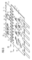
- Figure 1 shows a schematic, partially broken, perspective view of a power module 3 of a first embodiment of the invention.
- the reference numeral 1 denotes a ceramic plate having power semiconductor chips not shown as a substrate 1.
- the reference numeral 2 denotes a second substrate, which has a printed circuit board 11 made of glass fiber reinforced plastic and is folded over hingedly bent bonding wires 9 over the first substrate 1.
- Reference numeral 7 denotes the component side of the first substrate, and reference numeral 8 denotes the component side of the second substrate.
- the two components sides 7 and 8 face each other, since the two substrates are folded over one another in the plastic housing 18 are arranged.
- four outer planar conductors 27 for the power supply of the power semiconductor chips are arranged on the first substrate 1 with their inner flat conductor ends and protrude vertically out of the plastic housing 18.
- the hinge-like bent bonding wires 9 are arranged in a predetermined grid dimension on a bonding surface line 19 in the edge region 17 of the ceramic plate 10 of the first substrate 1.
- the ceramic plate 10 is mounted on a metal plate 25, which serves as a heat sink in this embodiment of the invention and forms an outer wall 26 of the plastic housing 18.
- the plastic housing 18 consists of a prefabricated plastic housing part 22, which is placed on the metal plate 25, and the cavity 23 between the preformed plastic housing 22 and the substrates 1 and 2 is cast after placement on the metal plate with a silicone composition.
- a power module which has arranged its sensors, logic circuits, control circuits and / or driver circuits on the second substrate 2 and on the intensively cooled first substrate 1, the power semiconductor chips in the form of MOS power transistors or bipolar power transistors with insulated Having gate or power diodes.
- FIGS. 2 to 6 show schematic diagrams of results and intermediate products of a method for producing a power module according to a further embodiment of the invention. Components of FIGS. 2 to 6 having the same functions as in FIG. 1 are identified by the same reference numerals and will not be discussed separately.
- FIG. 2 shows a ceramic substrate 1 with power semiconductor chips 4 and a row of outer flat conductors 27 for a power transmission and a further row with external contacts 28 for signal transmissions.
- the outer flat conductors 28 have a smaller cross section for signal transmissions on as the outer flat conductor 27 for power transmission.
- power diodes 29 and power transistors 30 are arranged, which are connected via bonds 13 with each other and with a printed conductor structure, not shown.
- a line 19, which is arranged in the edge region 17 of the ceramic substrate 10, has bonding surfaces 16, which are kept free of bonding connections 13. However, these bonding pads 16 are electrically connected to the not-shown trace structure. In addition, these bonding pads are partially electrically connected to the outer leads 28 for signal transmission via the wiring pattern on the ceramic substrate 10.
- FIG. 3 shows a schematic diagram with a first substrate 1, on which power semiconductor chips 4 are arranged, and with a second substrate 2, which has signal semiconductor chips, wherein the substrates 1 and 2 are mechanically and electrically connected to one another via bonding wires 9.
- the second substrate 2 of glass fiber reinforced circuit board 11 may include logic chips 12, control or driver chips 31 and / or temperature sensor chips 32 to provide an intelligent power module.
- This second substrate 2 has a conductor track structure, not shown in detail, which is electrically connected to the signal semiconductor chips 5 via bonding wires 33. In this case, a row 20 of bonding surfaces 16 of internal bonding wires 13 of the substrate 2 is kept free.
- the bonding surface line 20 in the edge region 17 of the substrate 2 is aligned in such a way that it is arranged parallel to the bonding surface line 19 of the substrate 1.
- Bonding wires 9 can thus be made with an inexpensive bonding method Aluminum with a minimum diameter of 100 microns connect the bonding surfaces 16 of the bonding line 20 with the bonding surfaces 16 of the bonding line 19 so that the ceramic substrate 10 is hingedly connected to the circuit board 11.
- the bonding wires 9 not only form a mechanical hinge but at the same time serve for the electrical connection between the conductor track structure of the ceramic substrate 10 and the conductor track structure of the printed circuit board 11.
- FIG. 4 shows a perspective schematic diagram of a power module 3 with the second substrate 2 folded over.
- the process of folding over the second substrate 2 via the first substrate 1 is shown in four positions, the arrows A, B and C representing the folding movement for the second substrate 2 .
- the bonding wires 9 bend in a hinge-like manner and, due to their stiffness after bending, define the distance d between the first substrate 1 and the second substrate 2.
- the bonding surfaces 16 in the edge regions 17 of the two substrates 1 and 2 are so arranged that with a bonding tool, the bonding wire 9 can be securely fixed to the bonding surfaces 16.
- FIG. 4 shows the contours of a plastic housing composition 21 which can be applied after the second substrate 2 has been folded over.
- FIG. 5 shows a perspective schematic diagram of a power module 3 with the second substrate 2 folded over.
- the plastic housing composition has been omitted in the representation of FIG. 5 in order to demonstrate the relatively flat arrangement of the two substrates 1 and 2 one above the other.
- a compact power module can be produced, which manages without complicated support structures and connection structures between the two substrates 1 and 2 and still forms a power module 3, which is equipped with intelligent control and logic technology.
- FIG. 6 shows a perspective schematic diagram of a power module 3 of a further embodiment of the invention, the outlines of the plastic housing 18 being shown with the dashed lines 35.
- This embodiment of the invention according to FIG. 6 differs from the embodiment according to FIG. 1 in that both the outer flat conductors 27 for power transmission and the outer flat conductors 28 protrude horizontally from the plastic housing 18 for signal transmission.
Abstract
Claims (23)
- Module de puissance comprenant un premier substrat (1) qui est équipé de puces en semiconducteur de puissance (4) et un deuxième substrat (2) qui est équipé de puces en semiconducteur de signal (5), les substrats (1, 2) étant orientés parallèlement l'un au-dessus de l'autre dans le module de puissance (3) et leurs côtés équipés (7, 8) étant disposés l'un vers l'autre et des surfaces de liaison (16) orientées les unes vers les autres étant à chaque fois disposées en une ligne (19, 20) dans les zones de bordure voisines (17) des côtés équipés (7 ou 8) du premier (1) ou du deuxième (2) substrat et les lignes (19, 20) étant disposées parallèlement l'une à l'autre, les surfaces de liaison du premier substrat (1) étant reliées électriquement avec les surfaces de liaison du deuxième substrat (2) par des fils de liaison courbés (9) d'une épaisseur de 100 µm à 300 µm disposés parallèlement les uns aux autres de telle sorte que du fait de la rigidité des fils de liaison (9), les deux substrats (1, 2) peuvent être fixés mécaniquement à une distance donnée l'un de l'autre puis incorporés dans une masse de boîtier en matière plastique (18).
- Module de puissance selon la revendication 1, caractérisé en ce que le premier substrat (1) équipé des puces en semiconducteur de puissance (4) est une plaque en céramique (10).
- Module de puissance selon la revendication 2, caractérisé en ce que le premier substrat (1) équipé des puces en semiconducteur de puissance (4) est une plaque en céramique multicouche (10).
- Module de puissance selon l'une des revendications précédentes, caractérisé en ce que le deuxième substrat (2) équipé des puces en semiconducteur de signal (5) est un circuit imprimé (11) en matière plastique renforcée de fibres de verre.
- Module de puissance selon la revendication 4, caractérisé en ce que le deuxième substrat (2) équipé des puces en semiconducteur de signal (5) est un circuit imprimé multicouche (11) en matière plastique renforcée de fibres de verre.
- Module de puissance selon l'une des revendications précédentes, caractérisé en ce que le deuxième substrat (2) équipé des puces en semiconducteur de signal (5) présente des composants semiconducteurs logiques (12).
- Module de puissance selon l'une des revendications précédentes, caractérisé en ce que le deuxième substrat (2) équipé des puces en semiconducteur de signal (5) présente des puces en semiconducteur (5) avec circuits de commande intégrés.
- Module de puissance selon l'une des revendications précédentes, caractérisé en ce que le deuxième substrat (2) équipé des puces en semiconducteur de signal (5) présente des puces en semiconducteur (5) avec circuits d'attaque intégrés.
- Module de puissance selon l'une des revendications précédentes, caractérisé en ce que le deuxième substrat (2) équipé des puces en semiconducteur de signal (5) présente des puces en semiconducteur (5) avec capteurs de température.
- Module de puissance selon l'une des revendications précédentes, caractérisé en ce que le deuxième substrat (2) équipé des puces en semiconducteur de signal (5) présente des puces en semiconducteur (5) avec des composants passifs tels que des résistances, des condensateurs ou des inductances.
- Module de puissance selon l'une des revendications précédentes, caractérisé en ce que le premier substrat (1) équipé des puces en semiconducteur de puissance (4) présente des puces en semiconducteur (4) avec des transistors de puissance bipolaires à gâchette isolée.
- Module de puissance selon l'une des revendications précédentes, caractérisé en ce que le premier substrat (1) équipé des puces en semiconducteur de puissance (4) présente des puces en semiconducteur (4) avec des transistors à effet de champ de puissance à oxyde métallique.
- Module de puissance selon l'une des revendications précédentes, caractérisé en ce que les puces en semiconducteur de puissance (4) sur le premier substrat (1) sont reliées directement entre elles par le biais de fils de liaison (13) et/ou de pistes conductrices sur le premier substrat (1) et avec les extrémités intérieures de conducteurs plats (14) de conducteurs plats externes (15).
- Module de puissance selon l'une des revendications précédentes, caractérisé en ce que les puces en semiconducteur de signal (5) sont reliées électriquement par le biais de pistes conductrices sur le deuxième substrat (2) et les fils de liaison courbés (9) avec les puces en semiconducteur de puissance (4) sur le premier substrat (1) et/ou avec des conducteurs plats externes (15).
- Module de puissance selon l'une des revendications précédentes, caractérisé en ce que les fils de liaison courbés (9) présentent de l'aluminium et/ou un alliage en aluminium.
- Procédé pour fabriquer un module de puissance selon la revendication 1, le procédé présentant les étapes suivantes :- mise à disposition d'un premier substrat (1) qui est équipé de puces en semiconducteur de puissance (4) et d'un deuxième substrat (2) qui est équipé de puces en semiconducteur de signal (5),- orientation des deux substrats (1, 2) de sorte que leurs côtés équipés (7, 8) soient disposés l'un à côté de l'autre, les substrats (1, 2) présentant des surfaces de liaison (16) à chaque fois disposées en une ligne dans les zones de bordure voisines (17) des côtés équipés (7 ou 8),- liaison des substrats (1, 2) avec les fils de liaison (9) sur les surfaces de liaison (16) des zones de bordure (17) correspondantes, les fils de liaison (9) étant disposés parallèlement les uns aux autres,- retournement du deuxième substrat (2) de 180°, les fils de liaison (9) exerçant la fonction d'une charnière de sorte que les substrats (1, 2) soient orientés en parallèle l'un au-dessus de l'autre et leurs côtés équipés (7, 8) soient disposés l'un vers l'autre,- emballage du module de puissance (3) dans un boîtier en matière plastique (18).
- Procédé selon la revendication 16, caractérisé en ce que pour la mise à disposition d'un premier substrat (1) muni de puces en semiconducteur de puissance (4), une plaque en céramique (10) est revêtue d'une structure à pistes conductrices qui présente dans une zone de bordure (17) une ligne (19) de surfaces de liaison (16) disposées les unes à côté des autres selon une cote de quadrillage prédéfinie, les puces en semiconducteur de puissance (4) étant disposées sur le premier substrat (1) et étant reliées entre elles ainsi qu'avec la structure à pistes conductrices par le biais de fils de liaison (13) en laissant libre la ligne de surfaces de liaison (19) et des extrémités intérieures de conducteurs plats (14) de conducteurs plats externes (15) étant en plus fixées sur la plaque en céramique (10) en étant reliées avec la structure à pistes conductrices.
- Procédé selon la revendication 16 ou la revendication 17, caractérisé en ce que pour la mise à disposition d'un deuxième substrat (2) muni de puces en semiconducteur de signal (5), un circuit imprimé (11) est muni d'une structure à pistes conductrices qui présente dans une zone de bordure une ligne (20) de surfaces de liaison (16) disposées les unes à côté des autres dont le nombre et la cote de quadrillage correspondent à ceux de la ligne de surfaces de liaison (19) du premier substrat (1), les puces en semiconducteur de signal (5) étant disposées sur le deuxième substrat (2) et étant reliées entre elles ainsi qu'avec la structure à pistes conductrices par le biais de fils de liaison (13) en laissant libre la ligne de surfaces de liaison (20).
- Procédé selon l'une des revendications 16 à 18, caractérisé en ce que pour l'orientation des deux substrats (1, 2), les lignes de surfaces de liaison (19, 20) des substrats (1, 2) sont disposées l'une à côté de l'autre de sorte que les fils de liaison (9) puissent être déposés sur les surfaces de liaison (16) orientées et adaptées les unes aux autres des deux substrats (1, 2).
- Procédé selon l'une des revendications 16 à 19, caractérisé en ce que la liaison des substrats (1, 2) par la dépose des fils de liaison (9) entre les surfaces de liaison (16) est réalisée au moyen d'une liaison sonique par thermocompression de fils de liaison (9) en aluminium et/ou en alliage d'aluminium ayant un diamètre entre 100 et 300 micromètres.
- Procédé selon la revendication 16, caractérisé en ce que l'emballage du module de puissance (3) dans un boîtier en matière plastique (18) est réalisé par technique de moulage par injection en incorporant les substrats (1, 2) disposés l'un au-dessus de l'autre dans une masse de boîtier en matière plastique (21).
- Procédé selon la revendication 16, caractérisé en ce que l'emballage du module de puissance (3) dans un boîtier en matière plastique (18) est réalisé en disposant les deux substrats (1, 2) dans un boîtier en matière plastique préfabriqué (22) et les espaces creux (23) entre les substrats (1, 2) et le boîtier en matière plastique préfabriqué (22) sont remplis d'une masse de silicone (24).
- Procédé selon la revendication 16, caractérisé en ce qu'avant l'emballage du module de puissance (3) dans un boîtier en matière plastique (18), le premier substrat (1) est monté sur une plaque métallique (25) de préférence en cuivre ou en un alliage de cuivre faisant office de dissipateur thermique, la plaque métallique (25) formant une paroi extérieure du boîtier en matière plastique (18).
Applications Claiming Priority (3)
| Application Number | Priority Date | Filing Date | Title |
|---|---|---|---|
| DE10214953 | 2002-04-04 | ||
| DE2002114953 DE10214953A1 (de) | 2002-04-04 | 2002-04-04 | Leistungsmodul mit mindestens zwei Substraten und Verfahren zu seiner Herstellung |
| PCT/DE2003/001067 WO2003085738A2 (fr) | 2002-04-04 | 2003-04-01 | Module de puissance comportant au moins deux substrats et procede permettant de le produire |
Publications (2)
| Publication Number | Publication Date |
|---|---|
| EP1490908A2 EP1490908A2 (fr) | 2004-12-29 |
| EP1490908B1 true EP1490908B1 (fr) | 2007-06-06 |
Family
ID=28684753
Family Applications (1)
| Application Number | Title | Priority Date | Filing Date |
|---|---|---|---|
| EP03724855A Expired - Fee Related EP1490908B1 (fr) | 2002-04-04 | 2003-04-01 | Module de puissance comportant au moins deux substrats et procede permettant de le produire |
Country Status (4)
| Country | Link |
|---|---|
| US (2) | US7176057B2 (fr) |
| EP (1) | EP1490908B1 (fr) |
| DE (2) | DE10214953A1 (fr) |
| WO (1) | WO2003085738A2 (fr) |
Families Citing this family (19)
| Publication number | Priority date | Publication date | Assignee | Title |
|---|---|---|---|---|
| DE10356367B4 (de) * | 2003-11-28 | 2009-06-10 | Georg Bernitz | Verfahren zur Herstellung eines Bauelements und Bauelement |
| DE102004043020B3 (de) | 2004-09-06 | 2006-04-27 | eupec Europäische Gesellschaft für Leistungshalbleiter mbH | Bonddraht und Bondverbindung |
| DE102005039165B4 (de) * | 2005-08-17 | 2010-12-02 | Infineon Technologies Ag | Draht- und streifengebondetes Halbleiterleistungsbauteil und Verfahren zu dessen Herstellung |
| DE102005061016B4 (de) * | 2005-12-19 | 2018-12-06 | Infineon Technologies Ag | Leistungshalbleitermodul, Verfahren zu seiner Herstellung und Verwendung in einem Schaltnetzteil |
| DE102006041983A1 (de) * | 2006-09-07 | 2008-03-27 | Robert Bosch Gmbh | Verfahren zum elektrischen Verbinden eines ersten Substrat mit einem zweiten Substrat |
| DE102006056363B4 (de) * | 2006-11-29 | 2010-12-09 | Infineon Technologies Ag | Halbleitermodul mit mindestens zwei Substraten und Verfahren zur Herstellung eines Halbleitermoduls mit zwei Substraten |
| JP5835166B2 (ja) * | 2012-09-07 | 2015-12-24 | 三菱電機株式会社 | 半導体装置、半導体装置の製造方法 |
| US9064869B2 (en) | 2013-08-23 | 2015-06-23 | Infineon Technologies Ag | Semiconductor module and a method for fabrication thereof by extended embedding technologies |
| DE102013219992A1 (de) | 2013-10-02 | 2015-04-02 | Conti Temic Microelectronic Gmbh | Schaltungsvorrichtung und Verfahren zu deren Herstellung |
| US9288907B2 (en) * | 2014-03-18 | 2016-03-15 | National Chung Shan Institute Of Science And Technology | Microelectronic 3D packaging structure and method of manufacturing the same |
| US9681558B2 (en) | 2014-08-12 | 2017-06-13 | Infineon Technologies Ag | Module with integrated power electronic circuitry and logic circuitry |
| US10211158B2 (en) | 2014-10-31 | 2019-02-19 | Infineon Technologies Ag | Power semiconductor module having a direct copper bonded substrate and an integrated passive component, and an integrated power module |
| TWI550391B (zh) | 2015-10-23 | 2016-09-21 | 台達電子工業股份有限公司 | 整合功率模組封裝結構 |
| GB2549128B (en) * | 2016-04-06 | 2019-06-12 | Ge Aviat Systems Ltd | Power control system with improved thermal performance |
| CN109804506B (zh) * | 2016-10-31 | 2020-07-28 | 株式会社自动网络技术研究所 | 配线模块 |
| EP3649671B1 (fr) * | 2017-07-12 | 2021-02-17 | ABB Power Grids Switzerland AG | Module à semi-conducteur de puissance avec un boîtier attaché à un composé de moulage et méthode de fabrication correspondante |
| EP3659177B1 (fr) | 2017-08-25 | 2023-10-25 | Huawei Technologies Co., Ltd. | Module à semi-conducteur et son procédé de fabrication |
| US11469163B2 (en) * | 2019-08-02 | 2022-10-11 | Semiconductor Components Industries, Llc | Low stress asymmetric dual side module |
| CN115841994A (zh) * | 2023-02-21 | 2023-03-24 | 广东汇芯半导体有限公司 | 一种半导体电路及压缩机 |
Family Cites Families (10)
| Publication number | Priority date | Publication date | Assignee | Title |
|---|---|---|---|---|
| CH668667A5 (de) | 1985-11-15 | 1989-01-13 | Bbc Brown Boveri & Cie | Leistungshalbleitermodul. |
| JPS62134956A (ja) * | 1985-12-09 | 1987-06-18 | Tdk Corp | パワ−用混成集積回路 |
| JP2829188B2 (ja) | 1992-04-27 | 1998-11-25 | 株式会社東芝 | 樹脂封止型半導体装置 |
| JP2725952B2 (ja) * | 1992-06-30 | 1998-03-11 | 三菱電機株式会社 | 半導体パワーモジュール |
| DE19741047C2 (de) | 1997-09-18 | 2002-11-14 | Conti Temic Microelectronic | Elektronisches Zündschloss für Kraftfahrzeuge |
| US6689372B1 (en) | 1998-08-04 | 2004-02-10 | Ciba Specialty Chemicals Corporation | Microbicidal active substances |
| DE19924991A1 (de) * | 1999-05-31 | 2000-12-21 | Tyco Electronics Logistics Ag | Intelligentes Leistungsmodul in Sandwich-Bauweise |
| JP2001085613A (ja) | 1999-09-13 | 2001-03-30 | Hitachi Ltd | トランスファモールド型パワーモジュール |
| ES2169687B2 (es) | 1999-09-30 | 2004-10-16 | Denso Corporation | Unidad electronica de control con elemento de activacion y elemento de tratamiento de control. |
| US6594152B2 (en) * | 1999-09-30 | 2003-07-15 | Intel Corporation | Board-to-board electrical coupling with conductive band |
-
2002
- 2002-04-04 DE DE2002114953 patent/DE10214953A1/de not_active Withdrawn
-
2003
- 2003-04-01 DE DE50307424T patent/DE50307424D1/de not_active Expired - Lifetime
- 2003-04-01 US US10/510,455 patent/US7176057B2/en not_active Expired - Lifetime
- 2003-04-01 EP EP03724855A patent/EP1490908B1/fr not_active Expired - Fee Related
- 2003-04-01 WO PCT/DE2003/001067 patent/WO2003085738A2/fr active IP Right Grant
-
2006
- 2006-12-11 US US11/636,836 patent/US7592696B2/en not_active Expired - Fee Related
Non-Patent Citations (1)
| Title |
|---|
| None * |
Also Published As
| Publication number | Publication date |
|---|---|
| US7592696B2 (en) | 2009-09-22 |
| US7176057B2 (en) | 2007-02-13 |
| DE10214953A1 (de) | 2003-10-30 |
| EP1490908A2 (fr) | 2004-12-29 |
| WO2003085738A3 (fr) | 2004-04-08 |
| US20050237722A1 (en) | 2005-10-27 |
| US20070099437A1 (en) | 2007-05-03 |
| DE50307424D1 (de) | 2007-07-19 |
| WO2003085738A2 (fr) | 2003-10-16 |
Similar Documents
| Publication | Publication Date | Title |
|---|---|---|
| EP1490908B1 (fr) | Module de puissance comportant au moins deux substrats et procede permettant de le produire | |
| DE102006056363B4 (de) | Halbleitermodul mit mindestens zwei Substraten und Verfahren zur Herstellung eines Halbleitermoduls mit zwei Substraten | |
| EP0221399B1 (fr) | Module semi-conducteur de puissance | |
| DE102006021959B4 (de) | Leistungshalbleiterbauteil und Verfahren zu dessen Herstellung | |
| DE19601372B4 (de) | Halbleitermodul | |
| DE19700963C2 (de) | Verfahren zur Herstellung eines Leistungsmoduls mit einer aktive Halbleiterbauelemente und passive Halbleiterbauelemente aufweisenden Schaltungsanordnung | |
| DE10259221A1 (de) | Elektronisches Bauteil mit einem Stapel aus Halbleiterchips und Verfahren zur Herstellung desselben | |
| WO1998015005A1 (fr) | Composant microelectronique a structure sandwich | |
| DE10393437T5 (de) | Halbleiterbauelementbaugruppe | |
| EP2422367A1 (fr) | Circuit encapsulé pour substrats comportant une couche d'absorption, et procédé de fabrication afférent | |
| EP1870934A1 (fr) | Module de convertisseur de puissance | |
| DE69723801T2 (de) | Herstellungsverfahren einer Kontaktgitter-Halbleiterpackung | |
| WO2004093190A2 (fr) | Module multipuces comportant plusieurs puces de semiconducteur et carte de circuits comportant plusieurs composants | |
| DE102004041088A1 (de) | Halbleiterbauteil in Flachleitertechnik mit einem Halbleiterchip | |
| DE19929606A1 (de) | Integrierte Schaltung und Verfahren zu ihrer Herstellung | |
| DE102006012007B4 (de) | Leistungshalbleitermodul mit oberflächenmontierbaren flachen Außenkontakten und Verfahren zur Herstellung desselben und dessen Verwendung | |
| DE10232788A1 (de) | Elektronisches Bauteil mit einem Halbleiterchip | |
| EP0219627B1 (fr) | Panneau de circuit imprimé à multicouches | |
| DE10157362B4 (de) | Leistungsmodul und Verfahren zu seiner Herstellung | |
| DE19781978B4 (de) | Gehäuse für eine integrierte Schaltung und Verfahren zu dessen Herstellung | |
| DE102017101185B4 (de) | Ein Halbleitermodul umfassend Transistorchips, Diodenchips und Treiberchips, angeordnet in einer gemeinsamen Ebene, Verfahren zu dessen Herstellung und integriertes Leistungsmodul | |
| DE102006024147B3 (de) | Elektronisches Modul mit Halbleiterbauteilgehäuse und einem Halbleiterchip und Verfahren zur Herstellung desselben | |
| EP3053192B1 (fr) | Dispositif avec un circuit et procédé de fabrication du dispositif | |
| EP0463589A2 (fr) | Module semi-conducteur de puissance comprenant une plaque intégrée de commande et une plaque de protection contre des erreurs | |
| DE10260005A1 (de) | Chippaket und Verfahren zu seiner Herstellung |
Legal Events
| Date | Code | Title | Description |
|---|---|---|---|
| PUAI | Public reference made under article 153(3) epc to a published international application that has entered the european phase |
Free format text: ORIGINAL CODE: 0009012 |
|
| 17P | Request for examination filed |
Effective date: 20040930 |
|
| AK | Designated contracting states |
Kind code of ref document: A2 Designated state(s): AT BE BG CH CY CZ DE DK EE ES FI FR GB GR HU IE IT LI LU MC NL PT RO SE SI SK TR |
|
| 17Q | First examination report despatched |
Effective date: 20060222 |
|
| GRAP | Despatch of communication of intention to grant a patent |
Free format text: ORIGINAL CODE: EPIDOSNIGR1 |
|
| RIC1 | Information provided on ipc code assigned before grant |
Ipc: H01L 23/31 20060101ALI20061025BHEP Ipc: H01L 23/433 20060101ALI20061025BHEP Ipc: H01L 25/16 20060101AFI20061025BHEP |
|
| GRAS | Grant fee paid |
Free format text: ORIGINAL CODE: EPIDOSNIGR3 |
|
| GRAA | (expected) grant |
Free format text: ORIGINAL CODE: 0009210 |
|
| AK | Designated contracting states |
Kind code of ref document: B1 Designated state(s): DE |
|
| REF | Corresponds to: |
Ref document number: 50307424 Country of ref document: DE Date of ref document: 20070719 Kind code of ref document: P |
|
| PLBE | No opposition filed within time limit |
Free format text: ORIGINAL CODE: 0009261 |
|
| STAA | Information on the status of an ep patent application or granted ep patent |
Free format text: STATUS: NO OPPOSITION FILED WITHIN TIME LIMIT |
|
| 26N | No opposition filed |
Effective date: 20080307 |
|
| PGFP | Annual fee paid to national office [announced via postgrant information from national office to epo] |
Ref country code: DE Payment date: 20190624 Year of fee payment: 17 |
|
| REG | Reference to a national code |
Ref country code: DE Ref legal event code: R119 Ref document number: 50307424 Country of ref document: DE |
|
| PG25 | Lapsed in a contracting state [announced via postgrant information from national office to epo] |
Ref country code: DE Free format text: LAPSE BECAUSE OF NON-PAYMENT OF DUE FEES Effective date: 20201103 |