EP1484732A2 - Système d'assistance à la conduite pour un véhicule - Google Patents
Système d'assistance à la conduite pour un véhicule Download PDFInfo
- Publication number
- EP1484732A2 EP1484732A2 EP04013034A EP04013034A EP1484732A2 EP 1484732 A2 EP1484732 A2 EP 1484732A2 EP 04013034 A EP04013034 A EP 04013034A EP 04013034 A EP04013034 A EP 04013034A EP 1484732 A2 EP1484732 A2 EP 1484732A2
- Authority
- EP
- European Patent Office
- Prior art keywords
- vehicle
- reaction force
- obstacle
- subject vehicle
- ttc
- Prior art date
- Legal status (The legal status is an assumption and is not a legal conclusion. Google has not performed a legal analysis and makes no representation as to the accuracy of the status listed.)
- Granted
Links
Images


Classifications
-
- G—PHYSICS
- G08—SIGNALLING
- G08G—TRAFFIC CONTROL SYSTEMS
- G08G1/00—Traffic control systems for road vehicles
- G08G1/16—Anti-collision systems
- G08G1/167—Driving aids for lane monitoring, lane changing, e.g. blind spot detection
-
- G—PHYSICS
- G08—SIGNALLING
- G08G—TRAFFIC CONTROL SYSTEMS
- G08G1/00—Traffic control systems for road vehicles
- G08G1/16—Anti-collision systems
- G08G1/166—Anti-collision systems for active traffic, e.g. moving vehicles, pedestrians, bikes
-
- B—PERFORMING OPERATIONS; TRANSPORTING
- B60—VEHICLES IN GENERAL
- B60K—ARRANGEMENT OR MOUNTING OF PROPULSION UNITS OR OF TRANSMISSIONS IN VEHICLES; ARRANGEMENT OR MOUNTING OF PLURAL DIVERSE PRIME-MOVERS IN VEHICLES; AUXILIARY DRIVES FOR VEHICLES; INSTRUMENTATION OR DASHBOARDS FOR VEHICLES; ARRANGEMENTS IN CONNECTION WITH COOLING, AIR INTAKE, GAS EXHAUST OR FUEL SUPPLY OF PROPULSION UNITS IN VEHICLES
- B60K26/00—Arrangements or mounting of propulsion unit control devices in vehicles
- B60K26/02—Arrangements or mounting of propulsion unit control devices in vehicles of initiating means or elements
- B60K26/021—Arrangements or mounting of propulsion unit control devices in vehicles of initiating means or elements with means for providing feel, e.g. by changing pedal force characteristics
-
- B—PERFORMING OPERATIONS; TRANSPORTING
- B60—VEHICLES IN GENERAL
- B60K—ARRANGEMENT OR MOUNTING OF PROPULSION UNITS OR OF TRANSMISSIONS IN VEHICLES; ARRANGEMENT OR MOUNTING OF PLURAL DIVERSE PRIME-MOVERS IN VEHICLES; AUXILIARY DRIVES FOR VEHICLES; INSTRUMENTATION OR DASHBOARDS FOR VEHICLES; ARRANGEMENTS IN CONNECTION WITH COOLING, AIR INTAKE, GAS EXHAUST OR FUEL SUPPLY OF PROPULSION UNITS IN VEHICLES
- B60K31/00—Vehicle fittings, acting on a single sub-unit only, for automatically controlling vehicle speed, i.e. preventing speed from exceeding an arbitrarily established velocity or maintaining speed at a particular velocity, as selected by the vehicle operator
- B60K31/0008—Vehicle fittings, acting on a single sub-unit only, for automatically controlling vehicle speed, i.e. preventing speed from exceeding an arbitrarily established velocity or maintaining speed at a particular velocity, as selected by the vehicle operator including means for detecting potential obstacles in vehicle path
Definitions
- the present invention relates to a technology for assisting driver operations, andmore specifically, it relates to a driving assist system for a vehicle that assists operations performed by the driver.
- Systems employed to assist driver operations in the related art include the system disclosed in Japanese Laid Open Patent Publication No. H10-211886. This system detects obstacles present around the vehicle and determines any latent risk potential that may exist. Then, the system inhibits a steering operation that would lead to an undesirable situation by controlling the steering assist torque based upon the calculated risk potential.
- a vehicle driving assist system comprises an obstacle detection means (10, 20) for detecting an obstacle present in each of two obstacle detection directions with respect to a subject vehicle; a TTC calculation means (50) for calculating a TTC between the subject vehicle and each of obstacles, that is a time to contact that expresses a length of time until the subject vehicle and the obstacle come to mutual contact, based on detection results of the obstacle detection means (10, 20); a lateral reaction force control means (50, 60) for controlling a reaction force generated at a vehicle operation equipment for drive operation in a lateral direction of the subject vehicle based on a first TTC which is smaller in the TTCs calculated in the TTC calculation means (50); and a longitudinal reaction force control means (50, 80, 90) for controlling a reaction force generated at a vehicle operation equipment for drive operation in a longitudinal direction of the subject vehicle based on a second TTC which is larger in the TTCs calculated in the TTC calculation means (50).
- a vehicle driving assist method detects an obstacle present in each of two obstacle detection directions with respect to a subject vehicle; calculates a TTC between the subject vehicle and each of obstacles, that is a time to contact that expresses a length of time until the subject vehicle and the obstacle come to mutual contact, based on information of the detected obstacle; controls a reaction force generated at a vehicle operation equipment for drive operation in a lateral direction of the subject vehicle based on a first TTC which is smaller in the calculated TTCs; and controls a reaction force generated at a vehicle operation equipment for drive operation in a longitudinal direction of the subject vehicle based on a second TTC which is larger in the calculated TTCs.
- FIG. 1 shows the structure of a vehicle driving assist system 1 of the first embodiment of the present invention
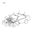
- FIG. 2 is a structural diagram of a vehicle fitted with the vehicle driving assist system 1.
- a laser radar 10 is attached to a front grill of the vehicle or to a bumper etc., and propagates infrared pulses in a forward horizontal direction for scanning.
- the laser radar 10 measures reflected radiation of infrared pulses reflected by a plurality of reflecting objects ahead, such as the rear of a vehicle in front, and detects a distance (inter-vehicle distance) from the subject vehicle to a preceding vehicle, a relative velocity (relative speed) of vehicles and a direction along which the preceding vehicle is present based on the elapsed time the reflected radiation to be received.
- the vehicle distance, relative speed and the direction thus detected are output to a controller 50. It is to be noted that the direction along which an object is present to the front of the vehicle is expressed as the relative angle to the subject vehicle.
- the laser radar 10 can scan the forward region which is about 6 degrees each side of an axis parallel to the vehicle longitudinal centerline, and objects existing within this range can be detected. In addition, the laser radar 10 detects a relative distance to an obstacle such as a pedestrian who may be present forward of the vehicle and a direction along which such as obstacle exists, as well as the inter-vehicle distance and the direction of the vehicle in front.
- an obstacle such as a pedestrian who may be present forward of the vehicle and a direction along which such as obstacle exists, as well as the inter-vehicle distance and the direction of the vehicle in front.
- a front camera 20 may be a compact CCD camera or CMOS camera mounted at the top of the windshield.
- the front camera 20 captures an image of the forward region to detect the road conditions ahead of the subject vehicle as an image and outputs the image signals to the controller 50.
- the detection range of the front camera 20 is approximately 30 degrees to each side of the longitudinal centerline of the subject vehicle along the horizontal direction, and the landscape of the road ahead contained in this range is taken in as an image.
- a vehicle speed sensor 20 detects a traveling speed of the subject vehicle from rotational speed of a wheel thereof or rotational speed of an output shaft of a transmission and outputs the vehicle speed to the controller 50.
- a steering angle sensor 40 detects a steering angle of a steering wheel 62. The detected steering angle is output to the controller 50.
- the controller 50 comprises a CPU and CPU peripheral devices, such as ROM, RAM etc. and executes the overall control of the driving assist system 1.
- the controller 50 detects the driving environment of the subject vehicle, i.e., obstacle conditions around the subject vehicle, based upon the vehicle speed input from the vehicle speed sensor 30, the distance information input from the laser radar 10 and the image information around the subject vehicle input from the front camera 20. It is to be noted that the controller 50 detects the obstacle conditions around the subject vehicle by executing image processing on the image information provided by the front camera 20.
- the obstacle conditions around the subject vehicle include the inter-vehicle distance to a preceding vehicle traveling ahead of the subject vehicle, a relative position and relative angle to a lane line (painted line) or a guardrail, such as a lateral position of the lane line with respect to the subject vehicle, and the shape of the lane line or the guardrail. Moreover, a pedestrian or motorcycle, etc. that crosses forward of the vehicle is also detected as an obstacle.
- the controller 50 calculates a risk potential of the subject vehicle with respect to each obstacle based upon the detected obstacle conditions and performs controls upon the vehicle according to the risk potential thus calculated as will be described later.
- a steering reaction force control device (a SF control device) 60 which is built into a steering system of the subject vehicle, controls the torque generated at a servomotor 61 in response to a command issued by the controller 50.
- the torque to be generated is controlled in conformance to a command value output from the SF control device 60 and thus, the level of the steering reaction force generated when the driver operates the steering wheel 62 can be controlled as desired through the servomotor 61.
- An accelerator pedal reaction force control device (an AF control device) 80 controls the torque generated at a servomotor 81 built into a link mechanism for an accelerator pedal 82 in response to a command issued by the controller 50.
- the reaction force to be generated is controlled in conformance to a command value output from the AF control device 80 and thus, the level of reaction force generated when the driver operates the accelerator pedal 82 can be controlled through the servomotor 81 as desired.
- the accelerator pedal reaction force characteristic (normal reaction force characteristic) is set in such a manner that , for instance, the accelerator pedal reaction force F increases linearly along with increase of the operation amount of the accelerator pedal 82.
- the normal reaction force characteristic may be obtained, for example, by spring force of a torsion spring (not shown in the drawings) provided at the center of rotation of the servo motor 82.
- a brake pedal reaction force control device (a BF control device) 90 controls a brake assist force, that is, power for assisting the driver to depress a brake pedal 92, to be generated at a brake booster 91 in response to a command issued by the controller 50.
- the brake booster 91 generates and controls the brake assist force in response to a command from the BF control device 90 so as to control reaction force generated when the driver depresses the brake pedal 92.
- the brake pedal reaction force becomes smaller, which makes it easier for the driver to depress the brake pedal 92.
- the brake pedal reaction force may increase linearly along with increase of the depression amount of the brake pedal 92.
- the controller 50 calculates the risk potential with respect to an obstacle that exists in the vehicle surroundings , for instance, painted line and a preceding vehicle running ahead of the subject vehicle. Then, based upon the calculated risk potential, the controller 50 performs reaction force controls in a longitudinal direction (back and forth direction ) and a lateral direction (right-and-left direction ) of the subject vehicle by controlling the accelerator pedal reaction force and the brake pedal reaction force, and the steering reaction force, respectively.
- total risk potentials in the longitudinal direction and in the lateral direction can be calculated by respectively integrating a longitudinal component and a lateral component of the risk potential corresponding to each obstacle exists in the vehicle surroundings. Then, the reaction force controls in the longitudinal direction and the lateral direction can be performed continuously based upon reaction force control quantities according to the total risk potentials in the longitudinal direction and in the lateral direction.
- two directions (obstacle detection directions) in the forward region of the subject vehicle are set to detect obstacles, and the risk potential for an obstacle that exists on each of the obstacle detection directions is calculated. Then, by comparing the risk potentials for those two obstacles, a balance between the longitudinal reaction force control quantity and the lateral reaction force control quantity is adjusted appropriately.
- reaction force control quantities i. e. , reaction force control command values for performing the steering reaction force control, the accelerator pedal reaction force control, and the brake pedal reaction force control are determined in the first embodiment referring to FIG. 3.
- FIG. 3 is a flow chart showing the procedural flow of a drive operation assist control program executed in the controller 50 in the first embodiment. These processing procedures are executed continuously at predetermined time intervals of, e. g. , 50msec.
- step S110 driving conditions are read in in step S110.
- an relative distance (inter-vehicle distance) D and a relative angle to a preceding vehicle ahead of the subject vehicle detected by the laser radar 10 are read in.
- Positions of lane lines relative to the subject vehicle, such as a lateral position and a relative angel, the shape of the lane line, a relative distance and a relative angle to the preceding vehicle, etc., based upon the image input from the front camera 20 are also read in.
- a subject vehicle speed V detected by the vehicle speed sensor 30 and a steering angle STR detected by the steering angle sensor 40 are read in.
- the controller 50 performs image processing upon the captured image from the front camera 20 and determines the type of the detected obstacle, in other words, whether the obstacle is a four-wheel vehicle, a two-wheel vehicle, a pedestrian or a lane line.
- step S120 a current conditions of the vehicle surroundings are recognized based on the traveling state data taken in in step S110.
- the relative position, and the moving direction and speed of each obstacle relative to the subject vehicle at this point are recognized based on the current traveling state data obtained in step S110 and the data of relative position and moving direction and speed of each obstacle with respect to the subject vehicle that were detected in the previous cycles and stored in memory in the controller 50. Then, the position and movement relative to the subject vehicle of another vehicle or lane line that is an obstacle for the subject vehicle to travel are recognized.
- step S130 the obstacle detection directions are set.
- a central angle ⁇ that determines the central line between two obstacle detection directions, and an opening angle ⁇ formed between the central line and each of the obstacle detection directions, as shown in FIG. 4 are calculated.
- an obstacle detection direction on the right is represented by an arrow DR
- an obstacle detection direction on the left is represented by an arrow DL.
- an approximate direction to which the subject vehicle is traveling is estimated from the subject vehicle speed V and the steering angle STR detected in step S110.
- the central angle ⁇ which substantially corresponds to an angle formed between the longitudinal centerline of the subject vehicle and the traveling direction is then determined.
- the traveling direction of the subject vehicle is roughly in proportion to the steering angle STR and in inverse proportion to the subject vehicle speed V.
- the central angle ⁇ becomes greater as the steering angle STR becomes larger, while the central angle ⁇ becomes smaller as the subject vehicle speed V becomes greater.
- the opening angle a is determined according to the subj ect vehicle speed V.
- a relationship between the subject vehicle speed V and the opening angle ⁇ is shown in FIG. 5.
- the opening angle ⁇ manifests a change in the traveling direction of the subject vehicle which is expected to occur when the steering angle STR changes slightly.
- the opening angle ⁇ is set to become smaller as the subject vehicle speed V becomes greater, as shown in FIG. 5, since a change in the traveling direction with respect to a change in the steering angle STR decreases as the subject vehicle speed V increases.
- step S140 a time to contact TTC to each obstacle that exists on the two obstacle detection directions set in step S130 is calculated respectively.
- the time to contact TTC (k) to each obstacle k can be calculated using the following (expression 1).
- TTC(k) D(k)/Vr(k)
- D(k) is a distance from the subject vehicle to the obstacle k
- Vr(k) is a relative velocity to the obstacle k
- the time to contact TTC is a physical quantity representing current degree of closeness of the subject vehicle to an obstacle, and it expresses a length of time until the subject vehicle and the obstacle come to mutual contact.
- TTC is calculated by dividing the distance D between the subject vehicle and the obstacle by the relative velocity Vr.
- a time to contact TTC(k) to an obstacle k that exists on the right obstacle detection direction shown by the arrow DR in the two obstacle detection directions is taken as a TTCr
- a time to contact TTC(k) to another obstacle k that exists on the left obstacle detection direction shown by the arrow DL is taken as a TTCl.
- a time to contact TTC for an obstacle that is the nearest to the subject vehicle is calculated.
- step S150 values of TTCr and TTCl to the right and left obstacles calculated in step S140 are compared to each other and it is determined as to which value is smaller between the TTCr and TTCl. If the time to contact TTCr to the right obstacle is smaller than the time to contact TTC1 to the left obstacle, step S160 is proceeded to.
- a risk potential RPlateral in a lateral direction of the subject vehicle is calculated based on the time to contact TTCr to the right which is smaller.
- a relationship between the time to contact TTC and the lateral risk potential RPlateral is shown in FIG. 6.
- the lateral risk potential RPlateral increases as the time to contact TTC becomes smaller and a degree of closeness to the obstacle becomes greater.
- the lateral risk potential RPlateral is fixed to a predetermined value RPm when the time to contact is smaller than a predetermined value TTC1.
- step S170 it is determined as to whether or not the time to contact TTCl to the left which is larger is smaller than a predetermined value T0.
- step S180 is proceeded to.
- a risk potential RPlongitudinal in a longitudinal direction of the subject vehicle is calculated based on the time to contact TTCl to the left.
- FIG. 7 shows a relationship between the time to contact TTC and the longitudinal risk potential RPlongitudinal. As shown in FIG. 7, the longitudinal risk potential RPlongitudinal increases as the time to contact TTC becomes smaller and a degree of closeness to the obstacle becomes greater. When the time to contact TTC is smaller than a predetermined value TTC2, the longitudinal risk potential RPlongitudinal is fixed to a predetermined value RPn.
- step S170 When a negative judgment is made in step S170 in that the larger time to contact TTCl to the left is equal to or greater than the predetermined value T0, the longitudinal risk potential RPlongitudinal is not calculated.
- the time to contact TTC is equal to or greater than the predetermined value T0, it can be determined that a degree of closeness to the obstacle is small enough not to perform the longitudinal reaction force control. That is, the prescribed value T0 is a threshold to determine whether a degree of closeness of the subject vehicle to the obstacle is substantial or trivial and to decide whether the longitudinal reaction force control is to be performed or not.
- the predetermined value T0 is set, for instance, approximately to seven seconds.
- step S260 is proceeded to.
- step S260 the lateral risk potential RPlateral is calculated based on the smaller time to contact TTCl to the left.
- the lateral risk potential RPlateral is calculated in accordance with the time to contact TTCl to the left using the map shown in FIG. 6.
- step S270 it is determined as to whether or not the larger time to contact TTCr to the right is smaller than the predetermine value T0.
- step S280 is proceeded to.
- step S280 the longitudinal risk potential RPlongitudinal is calculated based on the right time to contact TTCr.
- the longitudinal risk potential RPlongitudinal is calculated in accordance with the time to contact TTCr to the right using the map shown in FIG. 7.
- step S270 If a negative judgment is made in step S270 in that the larger time to contact TTCr to the right is equal to or greater than the predetermined value T0, the longitudinal risk potential RPlongitudinal is not calculated so as not to perform the longitudinal reaction force control.
- step S310 longitudinal control command values, i. e. , a reaction force control command value FA to be output to the AF control device 80 and a reaction force control command value FB to be output to the BF control device 90 are calculated based upon the longitudinal risk potential RPlongitudinal calculated in step S180 or S280.
- the reaction forces generated at the accelerator pedal 82 and at the brake pedal 92 are controlled respectively in accordance with the longitudinal risk potential RPlongitudinal in such a manner that the accelerator pedal 82 is returned and the brake pedal 92 is depressed easily as the RPlongitudinal increases. By doing this, the driver is prompted to switch over from the operation of the accelerator pedal 82 to the operation of the brake pedal 92.
- FIG. 8 shows a relationship between the longitudinal risk potential RPlongitudinal and the accelerator pedal reaction force control command value FA.
- the accelerator pedal reaction force control command value FA increases so as to increase the accelerator pedal reaction force as the longitudinal risk potential RPlongitudinal becomes greater, as shown in FIG. 8.
- the accelerator pedal reaction force control command value FA becomes fixed to a maximum value FAmax to generate the maximum accelerator pedal reaction force.
- FIG. 9 shows a relationship between the longitudinal risk potential RPlongitudinal and the brake pedal reaction force control command value FB.
- the brake pedal reaction force control value FB becomes smaller as the longitudinal risk potential RPlongitudinal increases in a range equal to or greater than the predetermined value RPmax so that the brake pedal reaction force becomes smaller and the brake assist force becomes greater.
- step S170 or S270 the longitudinal reaction force control is not performed.
- the normal reaction forces corresponding to operation amounts are generated at the accelerator pedal 82 and the brake pedal 92.
- a lateral control command value i.e., a steering reaction force control command value FS to be output to the SF control device 60 is calculated based on the lateral risk potential RPlateral calculated in step S160 or S260.
- the steering reaction force control command value FS is calculated in accordance with the lateral risk potential RPlateral so that a greater steering reaction force is generated in a direction for the subject vehicle to avoid a risk , i.e., in a direction to which the steering angle STR is put back as the RPlateral increases.
- FIG. 10 shows a relationship between the lateral risk potential RPlateral and the steering reaction force control command value FS.
- An absolute value of the steering reaction force control command value FS becomes greater as an absolute value of the lateral risk potential RPlateral becomes greater, whichmeans the steering reaction force in a direction to return the steering wheel 62 and to avoid a risk increases.
- FIG. 10 the lateral risk potential RPlateral to the obstacle that exists on the right obstacle detection direction is shown in the positive area and the lateral risk potential RPlateral to the obstacle that exists on the left obstacle detection direction is shown in the minus area.
- step S330 the longitudinal control command values FA and FB calculated in step S310 are output to the AF control device 80 and the BF control value 90, respectively, and the lateral control command value FS calculated in step S320 is output to the SF control device 60.
- the AF control device 80 controls the servo motor 81 so as to generate the operation reaction force in the accelerator pedal 82, which is obtained by adding the reaction force control command value FA input from the controller 50 to the normal reaction force characteristic.
- the BF control device 90 controls the brake booster 91 so as to generate the operation reaction force in the brake pedal 92, which is obtained by adding the reaction force control command value FB to the normal reaction force characteristic.
- the SF control device 60 controls the steering reaction force in accordance with the reaction force command value FS. The processing for this time then terminates.
- FIGS. 11A and 11B show figures for illustrating operations of the first embodiment.
- FIG. 11A shows a state where the subject vehicle travels on a straight road
- FIG. 11B shows a state where the subject vehicle travels on a curved road.
- the subject vehicle goes straight in a left region of the vehicle lane.
- the central angle ⁇ is 0 because the traveling direction of the subject vehicle is approximately towards the front of the vehicle, namely, the traveling direction is substantially parallel to the longitudinal centerline of the subj ect vehicle.
- the opening angle ⁇ is set to ⁇ ° to each side of the longitudinal centerline.
- the controller 50 calculates the time to contact TTCr and TTCl to each lane line.
- lengths of arrows DR and DL each represent the level of TTCr and TTCl.
- the controller 50 calculates the lateral risk potential RPlateral based on the left time to contact TTCl, and controls the steering reaction force according to the lateral risk potential RPlateral.
- the controller 50 calculates the longitudinal risk potential RPlongitudinal based on the time to contact TTCr. Then, the accelerator pedal reation force control and the brake pedal reation force control are performed according to the longitudinal risk potential RPlongitudinal. As a result, the steering reaction force corresponding to the left lane line is generated, and the accelerator pedal reaction force and the brake pedal reaction force corresponding to the right lane line are also generated.
- the subject vehicle is likely to deviate from the vehicle lane while traveling on a curved road.
- the central angle ⁇ is 0 because the traveling direction of the subject vehicle is approximately towards the front of the vehicle, namely, the traveling direction is substantially parallel to the longitudinal centerline of the subject vehicle.
- the opening angle ⁇ is set to ⁇ ° to each side of the longitudinal centerline.
- the controller 50 calculates the time to contact TTCr and TTCl to each lane line.
- lengths of arrows DR and DL each represent the level of TTCr and TTCl.
- the controller 50 calculates the lateral risk potential RPlateral based on the left time to contact TTCl, and controls the steering reaction force according to the lateral risk potential RPlateral. In addition, if the right time to contact TTCr is smaller than the predetermined value T0, the controller 50 calculates the longitudinal risk potential RPlongitudinal based on the time to contact TTCr. Then, the accelerator pedal reaction force control and the brake pedal reaction force control are performed according to the longitudinal risk potential RPlongitudinal.
- the steering reaction force is generated in a direction to which the steering wheel 62 is returned when the subject vehicle may deviate from the curved road as shown in FIG. 11B, so as to lead the drive operation of the driver to an appropriate direction.
- the reaction force control quantities are calculated to small values. Then, if the subject vehicle keeps traveling straight and approaches further with the lane line, the left time to contact TTCl and the right time to contact TTCr both become small and thus, the reaction force control quantities in the lateral direction and the longitudinal direction of the subject vehicle become greater.
- the steering reaction force is generated so as to prevent the subject vehicle from deviating from the curve and also the reaction forces are generated to prompt the driver's deceleration operation.
- the reaction forces are controlled while an appropriate balance is achieved in the reaction force controls in the longitudinal direction and the lateral direction.
- the reaction force controls in the lateral and longitudinal direction of the subject vehicle are then performed in accordance with the time to contact TTCr and TTCl to each obstacle.
- the reaction force control in the longitudinal direction of the subject vehicle is performed only when the same obstacle is detected in both the right obstacle detection direction and the left obstacle detection direction.
- reaction force control quantities i.e., reaction force control command values for performing the steering reaction force control, the accelerator pedal reaction force control, and the brake pedal reaction force control are determined in the second embodiment referring to FIG. 12.
- FIG. 12 is a flow chart showing the procedural flow of a drive operation assist control program executed in the controller 50 in the second embodiment. These processing procedures are executed continuously at predetermined time intervals of, e. g. , 50msec.
- steps S1110 to S1160 are identical to the processing in step S110 to S160 which are explained referring to the flow chart of FIG. 3 in the first embodiment, thus their explanations are omitted herein.
- a risk potential RPlateral in the lateral direction of the subject vehicle is calculated based on the time to contact TTCr to the right which is smaller, the processing proceeds to step S1170.
- step S1170 it is determined as to whether or not obstacles on the right and left obstacle detection directions are the same. For instance, when the same lane line is present on both the right and left obstacle detection directions as shown in FIG. 13B, step S1180 is proceeded to.
- step S1180 a risk potential RPlongitudinal in the longitudinal direction of the subject vehicle is calculated based on the time to contact TTCl to the left which is greater.
- the longitudinal risk potential RPlongitudinal is calculated using the map shown in FIG. 7.
- lane lines present on the right and left obstacle detection directions are different as shown in FIG. 13A, the longitudinal risk potential RPlongitudinal is not calculated. It may be determined as to whether or not obstacles on the right and left obstacle detection directions are the same by applying image processing to the detected image from the front camera 20 and determining the type of the detected obstacle.
- step S1260 When it is determined in step S1150 that the time to contact TTCl to the left is equal to or smaller than the time to contact TTCr to the right, step S1260 is proceeded to. In step S1260, the lateral riskpotential RPlateral is caluculated based on the time to contact TTCl to the left referring to FIG. 6.
- step S1270 It is determined as to whether or not obstacles on the right and left obstacle detection directions are the same. When the same obstacle is detected on both the right and left obstacle detection directions, step S1280 is proceeded to. In step S1280, the longitudinal risk potential RPlongitudinal is calculated based on the right time to contact TTCr referring to FIG. 7. On the other hand, when the obstacles detected on the right and left obstacle detection directions are different, the longitudinal risk potential RPlongitudinal is not calculated.
- steps S1310 to S1330 are identical to the processing in steps S310 to S330 shown in the flow chart of FIG. 3, thus their explanations are omitted.
- FIG. 13A shows a state where the subject vehicle travels on a straight road at a small yaw angle
- FIG. 11B shows a state where the subject vehicle is likely to deviate from a straight road at a large yaw angle.
- the subject vehicle goes straight in a left region of the vehicle lane.
- the central angle ⁇ is 0 because the traveling direction of the subject vehicle is approximately towards the front of the vehicle, namely, the traveling direction is substantially parallel to the longitudinal centerline of the subject vehicle.
- the opening angle ⁇ is set to ⁇ ° to each side of the longitudinal centerline.
- the controller 50 calculates the time to contact TTCr and TTCl to each lane line.
- lengths of arrows DR and DL each represent the level of TTCr and TTCl.
- the controller 50 calculates the lateral risk potential RPlateral based on the left time to contact TTCl which is smaller in the right and left time to contact TTCr and TTCl.
- the steering reaction force is then controlled according to the lateral risk potential RPlateral.
- obstacles detected in the right and left obstacle detection directions are not the same.
- the longitudinal risk potential RPlongitudinal is not calculated and the longitudinal reaction force control is not performed.
- only the lateral reaction force control is performed.
- the controller 50 calculates the lateral risk potential RPlateral based on the left time to contact TTCl which is smaller, and controls the steering reaction force accordingtothelateralriskpotentialRPlateral.
- the longitudinal risk potential RPlongitudinal is calculated based on the right time to contact TTCr which is larger, and the accelerator pedal reaction force control and the brake pedal reaction force control are performed according to the longitudinal risk potential RPlongitudinal thus calculated.
- the lateral reaction force control and the longitudinal reaction force control for the subject vehicle are performed so as to lead the driver's steering operation to an appropriate direction and so as to prompt the driver's deceleration operation when the subject vehicle is likely to deviate from the vehicle lane. If the subject vehicle approaches the lane line further than the situation shown in FIG. 13B, the reaction force control quantities in the longitudinal direction and the lateral direction increases so as to urge the driver to perform the drive operation to avoid the deviation from the vehicle lane.
- the controller 50 determines the type of the obstacle that exists on each of the two obstacle detection directions and performs the reaction force control in the longitudinal direction of the subject vehicle when the obstacles on the two directions are the same, in addition to the lateral reaction force control. Accordingly, it is possible to lead driver's operation to an appropriate direction by prompting the driver ' s deceleration operation and leading the steering operation to an appropriate direction when the subject vehicle is likely to deviate from the vehicle lane as shown in FIG. 13B.
- the reaction force control in the longitudinal direction of the subject vehicle is not performed when the different obstacles are present in the two obstacle detection directions.
- the accelerator pedal reaction force control device 80 and the brake pedal reaction force control device 90 are used as vehicle operation equipments for drive operation in the longitudinal direction.
- the present invention is not to be limited to this structure, and it is acceptable to utilize, for instance, only one of the reaction force control devices 80 and 90 to control the reaction force in the longitudinal direction.
- the brake assist force is generated by using the negative pressure of an engine at the brake booster 91, but the present invention is not to be limited to this structure.
- the brake assist force may instead be generated by using hydraulic power which is controlled by a computer.
- the steering wheel 62 is used by way of example as an vehicle operation equipment for drive operation in the lateral direction.
- the vehicle to which the vehicle driving assist system of the present invention is mounted is not to be limited to the structure shown in FIG. 2.
- the present invention is not to be limited to this structure.
- a millimeter wave radar, a magnetic nail or Differential GPS system, etc. can instead be used as a means for detecting an obstacle.
- a device that performs image processing upon the image signal from the front camera 20 may be installed independently of the controller 50.
Landscapes
- Physics & Mathematics (AREA)
- General Physics & Mathematics (AREA)
- Steering Control In Accordance With Driving Conditions (AREA)
- Traffic Control Systems (AREA)
- Control Of Driving Devices And Active Controlling Of Vehicle (AREA)
- Regulating Braking Force (AREA)
- Auxiliary Drives, Propulsion Controls, And Safety Devices (AREA)
Applications Claiming Priority (2)
| Application Number | Priority Date | Filing Date | Title |
|---|---|---|---|
| JP2003159296 | 2003-06-04 | ||
| JP2003159296A JP3896993B2 (ja) | 2003-06-04 | 2003-06-04 | 車両用運転操作補助装置および車両用運転操作補助装置を備える車両 |
Publications (3)
| Publication Number | Publication Date |
|---|---|
| EP1484732A2 true EP1484732A2 (fr) | 2004-12-08 |
| EP1484732A3 EP1484732A3 (fr) | 2005-07-13 |
| EP1484732B1 EP1484732B1 (fr) | 2008-03-05 |
Family
ID=33157176
Family Applications (1)
| Application Number | Title | Priority Date | Filing Date |
|---|---|---|---|
| EP04013034A Expired - Fee Related EP1484732B1 (fr) | 2003-06-04 | 2004-06-02 | Système d'assistance à la conduite pour un véhicule |
Country Status (4)
| Country | Link |
|---|---|
| US (1) | US7136755B2 (fr) |
| EP (1) | EP1484732B1 (fr) |
| JP (1) | JP3896993B2 (fr) |
| DE (1) | DE602004012196T2 (fr) |
Cited By (5)
| Publication number | Priority date | Publication date | Assignee | Title |
|---|---|---|---|---|
| WO2007042355A1 (fr) * | 2005-10-11 | 2007-04-19 | Robert Bosch Gmbh | Systeme d'aide a la conduite |
| WO2009095487A1 (fr) * | 2008-01-31 | 2009-08-06 | Continental Teves Ag & Co. Ohg | Système d'assistance à la conduite |
| CN102066184A (zh) * | 2009-06-03 | 2011-05-18 | 丰田自动车株式会社 | 车辆的转向装置以及该转向装置的设定装置 |
| CN102267462A (zh) * | 2010-05-13 | 2011-12-07 | 株式会社万都 | 车道维持控制方法 |
| CN103287330A (zh) * | 2013-06-24 | 2013-09-11 | 成都衔石科技有限公司 | 智能汽车的多功能智能预警系统 |
Families Citing this family (23)
| Publication number | Priority date | Publication date | Assignee | Title |
|---|---|---|---|---|
| JP3531640B2 (ja) * | 2002-01-10 | 2004-05-31 | 日産自動車株式会社 | 車両用運転操作補助装置 |
| JP3873876B2 (ja) | 2002-12-06 | 2007-01-31 | 日産自動車株式会社 | 車両用運転操作補助装置およびその装置を備えた車両 |
| JP4367319B2 (ja) * | 2004-11-12 | 2009-11-18 | 日産自動車株式会社 | 車両用運転操作補助装置および車両用運転操作補助装置を備えた車両 |
| JP4781707B2 (ja) * | 2005-04-15 | 2011-09-28 | 富士重工業株式会社 | 車両の運転支援装置 |
| JP4735310B2 (ja) * | 2005-04-15 | 2011-07-27 | 株式会社デンソー | 走行支援装置 |
| DE102005060820B4 (de) * | 2005-12-20 | 2022-05-19 | Zf Cv Systems Hannover Gmbh | Verfahren zur Unterstützung eines Führens eines Fahrzeuges |
| JP5055812B2 (ja) * | 2006-04-07 | 2012-10-24 | マツダ株式会社 | 車両の障害物検知装置 |
| JP4458072B2 (ja) * | 2006-06-28 | 2010-04-28 | 日産自動車株式会社 | 車両用運転操作補助装置および車両用運転操作補助装置を備えた車両 |
| JP4876847B2 (ja) * | 2006-10-18 | 2012-02-15 | 株式会社デンソー | 車両の進行方向推定装置及び運転支援システム |
| JP5200732B2 (ja) * | 2008-07-29 | 2013-06-05 | 日産自動車株式会社 | 走行制御装置、及び走行制御方法 |
| JP5255988B2 (ja) * | 2008-10-22 | 2013-08-07 | 富士重工業株式会社 | 操舵支援装置 |
| JP2010221993A (ja) * | 2009-02-27 | 2010-10-07 | Nissan Motor Co Ltd | 車両用運転操作補助装置、車両用運転操作補助方法および自動車 |
| JP2010221995A (ja) * | 2009-02-27 | 2010-10-07 | Nissan Motor Co Ltd | 車両用運転操作補助装置、車両用運転操作補助方法および自動車 |
| JP5526717B2 (ja) * | 2009-02-27 | 2014-06-18 | 日産自動車株式会社 | 車両用運転操作補助装置、車両用運転操作補助方法および自動車 |
| JP5381160B2 (ja) * | 2009-02-27 | 2014-01-08 | 日産自動車株式会社 | 車両用運転操作補助装置および車両用運転操作補助方法 |
| JP5600907B2 (ja) * | 2009-08-28 | 2014-10-08 | 日産自動車株式会社 | 車両用運転操作補助装置、車両用運転操作補助方法および自動車 |
| KR101102144B1 (ko) * | 2009-11-17 | 2012-01-02 | 주식회사 만도 | 차선 유지 제어 방법 및 시스템 |
| JP5229341B2 (ja) * | 2011-02-28 | 2013-07-03 | 株式会社デンソー | アクセルペダル誤操作対応装置およびアクセルペダル誤操作対応装置用のプログラム |
| JP5543501B2 (ja) * | 2012-01-27 | 2014-07-09 | 株式会社日本自動車部品総合研究所 | 車両制御装置 |
| JP6661213B2 (ja) * | 2015-12-07 | 2020-03-11 | 株式会社Subaru | 車両の運転支援制御装置 |
| JP2017109560A (ja) * | 2015-12-15 | 2017-06-22 | 株式会社Subaru | 車両の運転支援制御装置 |
| US11897498B2 (en) * | 2018-02-15 | 2024-02-13 | Toyota Motor Europe | Control method for a vehicle, computer program, non-transitory computer readable medium, and automated driving system |
| US10723362B2 (en) * | 2018-06-05 | 2020-07-28 | Denso International America, Inc. | Driver assistance system operating based on autonomous statuses of host and local vehicles while in a multi-level autonomous environment |
Citations (1)
| Publication number | Priority date | Publication date | Assignee | Title |
|---|---|---|---|---|
| US6275773B1 (en) * | 1993-08-11 | 2001-08-14 | Jerome H. Lemelson | GPS vehicle collision avoidance warning and control system and method |
Family Cites Families (33)
| Publication number | Priority date | Publication date | Assignee | Title |
|---|---|---|---|---|
| US226232A (en) * | 1880-04-06 | Machine for forming metallic shoe-shanks | ||
| US336802A (en) * | 1886-02-23 | Thaddeus faiebanks | ||
| US682959A (en) * | 1901-01-07 | 1901-09-17 | Seng Co | Spring-catch. |
| JPS517892B1 (fr) | 1970-11-07 | 1976-03-11 | ||
| JPS5733048A (en) | 1980-08-04 | 1982-02-23 | Honda Motor Co Ltd | Throttle reaction control device of car |
| JPH0558319A (ja) * | 1991-08-27 | 1993-03-09 | Mazda Motor Corp | 車両の接触防止装置 |
| US5680097A (en) * | 1992-12-10 | 1997-10-21 | Mazda Motor Corporation | Vehicle run safety apparatus |
| JPH09277850A (ja) | 1996-04-17 | 1997-10-28 | Nissan Motor Co Ltd | 自動車のアクセル操作装置 |
| DE19620929A1 (de) | 1996-05-24 | 1997-11-27 | Porsche Ag | Längsregelsystem für Kraftfahrzeuge mit haptischem Gaspedal |
| JPH10166890A (ja) | 1996-12-04 | 1998-06-23 | Suzuki Motor Corp | 警報装置 |
| JPH10166889A (ja) | 1996-12-04 | 1998-06-23 | Suzuki Motor Corp | 警報装置 |
| JPH10211886A (ja) | 1997-01-29 | 1998-08-11 | Honda Motor Co Ltd | 車両の操舵装置 |
| DE19821163A1 (de) | 1998-05-12 | 1999-11-18 | Volkswagen Ag | Fahrer-Assistenzsystem und Verfahren zu dessen Betrieb |
| JP3828663B2 (ja) | 1998-06-11 | 2006-10-04 | 本田技研工業株式会社 | 車両の障害物回避制御装置 |
| US6269308B1 (en) * | 1998-08-20 | 2001-07-31 | Honda Giken Kogyo Kabushiki Kaisha | Safety running system for vehicle |
| JP3704987B2 (ja) | 1999-01-27 | 2005-10-12 | 三菱自動車工業株式会社 | 車両走行制御装置 |
| JP3800007B2 (ja) * | 2001-01-09 | 2006-07-19 | 日産自動車株式会社 | 制動制御装置 |
| JP2002323565A (ja) | 2001-04-27 | 2002-11-08 | Denso Corp | 障害物認識装置 |
| JP4173292B2 (ja) | 2001-08-23 | 2008-10-29 | 日産自動車株式会社 | 車両用運転操作補助装置 |
| EP1285842B1 (fr) * | 2001-08-23 | 2008-05-28 | Nissan Motor Co., Ltd. | Système d'assistance à la conduite |
| EP1332910B1 (fr) | 2002-02-01 | 2009-11-04 | Nissan Motor Co., Ltd. | Méthode et système pour améliorer l'assistance au conducteur |
| JP3573134B2 (ja) | 2002-02-25 | 2004-10-06 | 日産自動車株式会社 | 車両用運転操作補助装置 |
| JP3613264B2 (ja) * | 2002-06-18 | 2005-01-26 | 日産自動車株式会社 | 車両用運転操作補助装置 |
| JP3838166B2 (ja) * | 2002-06-20 | 2006-10-25 | 日産自動車株式会社 | 車両用運転操作補助装置 |
| JP3941640B2 (ja) | 2002-09-18 | 2007-07-04 | 日産自動車株式会社 | 車両用運転操作補助装置、車両用運転操作補助方法、およびその方法を適用した車両 |
| JP3750644B2 (ja) | 2002-09-27 | 2006-03-01 | 日産自動車株式会社 | 車両用運転操作補助装置、車両用運転操作補助方法、およびその方法を適用した車両 |
| JP3938023B2 (ja) | 2002-11-27 | 2007-06-27 | 日産自動車株式会社 | リスクポテンシャル算出装置、車両用運転操作補助装置、その装置を備える車両およびリスクポテンシャル演算方法 |
| JP3873876B2 (ja) * | 2002-12-06 | 2007-01-31 | 日産自動車株式会社 | 車両用運転操作補助装置およびその装置を備えた車両 |
| JP3982456B2 (ja) | 2003-06-04 | 2007-09-26 | 日産自動車株式会社 | 車両用リスクポテンシャル算出装置、車両用運転操作補助装置、車両用運転操作補助装置を備える車両およびリスクポテンシャル算出方法 |
| JP3882797B2 (ja) | 2003-08-08 | 2007-02-21 | 日産自動車株式会社 | 車両用運転操作補助装置および車両用運転操作補助装置を備える車両 |
| JP4239771B2 (ja) | 2003-09-18 | 2009-03-18 | 日産自動車株式会社 | 車両用運転操作補助装置および車両用運転操作補助装置を備えた車両 |
| JP4487534B2 (ja) | 2003-10-23 | 2010-06-23 | 日産自動車株式会社 | 車両用運転操作補助装置および車両用運転操作補助装置を備えた車両 |
| JP4367322B2 (ja) * | 2004-11-26 | 2009-11-18 | 日産自動車株式会社 | 車両用運転操作補助装置および車両用運転操作補助装置を備えた車両 |
-
2003
- 2003-06-04 JP JP2003159296A patent/JP3896993B2/ja not_active Expired - Fee Related
-
2004
- 2004-06-02 DE DE602004012196T patent/DE602004012196T2/de active Active
- 2004-06-02 EP EP04013034A patent/EP1484732B1/fr not_active Expired - Fee Related
- 2004-06-03 US US10/859,360 patent/US7136755B2/en not_active Expired - Fee Related
Patent Citations (1)
| Publication number | Priority date | Publication date | Assignee | Title |
|---|---|---|---|---|
| US6275773B1 (en) * | 1993-08-11 | 2001-08-14 | Jerome H. Lemelson | GPS vehicle collision avoidance warning and control system and method |
Cited By (6)
| Publication number | Priority date | Publication date | Assignee | Title |
|---|---|---|---|---|
| WO2007042355A1 (fr) * | 2005-10-11 | 2007-04-19 | Robert Bosch Gmbh | Systeme d'aide a la conduite |
| WO2009095487A1 (fr) * | 2008-01-31 | 2009-08-06 | Continental Teves Ag & Co. Ohg | Système d'assistance à la conduite |
| CN102066184A (zh) * | 2009-06-03 | 2011-05-18 | 丰田自动车株式会社 | 车辆的转向装置以及该转向装置的设定装置 |
| CN102066184B (zh) * | 2009-06-03 | 2013-06-19 | 丰田自动车株式会社 | 车辆的转向装置以及该转向装置的设定装置 |
| CN102267462A (zh) * | 2010-05-13 | 2011-12-07 | 株式会社万都 | 车道维持控制方法 |
| CN103287330A (zh) * | 2013-06-24 | 2013-09-11 | 成都衔石科技有限公司 | 智能汽车的多功能智能预警系统 |
Also Published As
| Publication number | Publication date |
|---|---|
| EP1484732B1 (fr) | 2008-03-05 |
| DE602004012196T2 (de) | 2009-03-12 |
| US7136755B2 (en) | 2006-11-14 |
| JP3896993B2 (ja) | 2007-03-22 |
| EP1484732A3 (fr) | 2005-07-13 |
| JP2004362224A (ja) | 2004-12-24 |
| US20040249550A1 (en) | 2004-12-09 |
| DE602004012196D1 (de) | 2008-04-17 |
Similar Documents
| Publication | Publication Date | Title |
|---|---|---|
| US7136755B2 (en) | Driving assist system for vehicle | |
| US6832157B2 (en) | Driving assist system | |
| JP4173292B2 (ja) | 車両用運転操作補助装置 | |
| US11072331B2 (en) | Vehicle control device, vehicle control method and vehicle control program | |
| US8200419B2 (en) | Braking control system and braking control method | |
| US20180201271A1 (en) | Vehicle control device, vehicle control method, and vehicle control program | |
| US20200238980A1 (en) | Vehicle control device | |
| US20200353918A1 (en) | Vehicle control device | |
| US11072334B2 (en) | Vehicle control system | |
| JP2007269312A (ja) | 車両用運転操作補助装置 | |
| JP4193903B2 (ja) | 車両用運転操作補助装置 | |
| US20220161849A1 (en) | Vehicle control device, vehicle control method, and non-transitory computer-readable recording medium recording program | |
| JP2003276538A (ja) | 障害物予測装置 | |
| JP3963119B2 (ja) | 車両用運転操作補助装置 | |
| WO2020020525A1 (fr) | Procédé de réalisation d'une manœuvre de dépassement comprenant la prise en compte d'une distance de sécurité, composant d'analyse, un système d'aide à la conduite, ainsi que véhicule | |
| JP4055721B2 (ja) | 車両用運転操作補助装置および車両用運転操作補助装置を備えた車両 | |
| JP4396281B2 (ja) | 車両用運転操作補助装置 | |
| JP3767538B2 (ja) | 車両用運転操作補助装置、車両用運転操作補助方法、およびその方法を適用した車両 | |
| JP2024030413A (ja) | 車両制御装置、車両制御方法、およびプログラム | |
| JP4419513B2 (ja) | 車両用運転操作補助装置および車両用運転操作補助装置を備えた車両 | |
| JP6832261B2 (ja) | 車両制御装置、車両制御方法、およびプログラム | |
| JP4622465B2 (ja) | 車両用運転操作補助装置および車両用運転操作補助装置を備えた車両 | |
| US20210300332A1 (en) | Vehicle control system | |
| JP4003597B2 (ja) | 車両用運転操作補助装置、車両用運転操作補助方法、およびその方法を適用した車両 | |
| JP3891144B2 (ja) | 車両用運転操作補助装置およびその装置を備えた車両 |
Legal Events
| Date | Code | Title | Description |
|---|---|---|---|
| PUAI | Public reference made under article 153(3) epc to a published international application that has entered the european phase |
Free format text: ORIGINAL CODE: 0009012 |
|
| 17P | Request for examination filed |
Effective date: 20040602 |
|
| AK | Designated contracting states |
Kind code of ref document: A2 Designated state(s): AT BE BG CH CY CZ DE DK EE ES FI FR GB GR HU IE IT LI LU MC NL PL PT RO SE SI SK TR |
|
| AX | Request for extension of the european patent |
Extension state: AL HR LT LV MK |
|
| PUAL | Search report despatched |
Free format text: ORIGINAL CODE: 0009013 |
|
| AK | Designated contracting states |
Kind code of ref document: A3 Designated state(s): AT BE BG CH CY CZ DE DK EE ES FI FR GB GR HU IE IT LI LU MC NL PL PT RO SE SI SK TR |
|
| AX | Request for extension of the european patent |
Extension state: AL HR LT LV MK |
|
| AKX | Designation fees paid |
Designated state(s): DE FR GB |
|
| GRAP | Despatch of communication of intention to grant a patent |
Free format text: ORIGINAL CODE: EPIDOSNIGR1 |
|
| GRAS | Grant fee paid |
Free format text: ORIGINAL CODE: EPIDOSNIGR3 |
|
| GRAA | (expected) grant |
Free format text: ORIGINAL CODE: 0009210 |
|
| AK | Designated contracting states |
Kind code of ref document: B1 Designated state(s): DE FR GB |
|
| REG | Reference to a national code |
Ref country code: GB Ref legal event code: FG4D |
|
| REF | Corresponds to: |
Ref document number: 602004012196 Country of ref document: DE Date of ref document: 20080417 Kind code of ref document: P |
|
| ET | Fr: translation filed | ||
| PLBE | No opposition filed within time limit |
Free format text: ORIGINAL CODE: 0009261 |
|
| STAA | Information on the status of an ep patent application or granted ep patent |
Free format text: STATUS: NO OPPOSITION FILED WITHIN TIME LIMIT |
|
| 26N | No opposition filed |
Effective date: 20081208 |
|
| REG | Reference to a national code |
Ref country code: FR Ref legal event code: PLFP Year of fee payment: 12 |
|
| PGFP | Annual fee paid to national office [announced via postgrant information from national office to epo] |
Ref country code: GB Payment date: 20150527 Year of fee payment: 12 Ref country code: DE Payment date: 20150527 Year of fee payment: 12 |
|
| PGFP | Annual fee paid to national office [announced via postgrant information from national office to epo] |
Ref country code: FR Payment date: 20150608 Year of fee payment: 12 |
|
| REG | Reference to a national code |
Ref country code: DE Ref legal event code: R119 Ref document number: 602004012196 Country of ref document: DE |
|
| GBPC | Gb: european patent ceased through non-payment of renewal fee |
Effective date: 20160602 |
|
| REG | Reference to a national code |
Ref country code: FR Ref legal event code: ST Effective date: 20170228 |
|
| PG25 | Lapsed in a contracting state [announced via postgrant information from national office to epo] |
Ref country code: FR Free format text: LAPSE BECAUSE OF NON-PAYMENT OF DUE FEES Effective date: 20160630 Ref country code: DE Free format text: LAPSE BECAUSE OF NON-PAYMENT OF DUE FEES Effective date: 20170103 |
|
| PG25 | Lapsed in a contracting state [announced via postgrant information from national office to epo] |
Ref country code: GB Free format text: LAPSE BECAUSE OF NON-PAYMENT OF DUE FEES Effective date: 20160602 |