EP1484544A1 - Leitungsdurchführung für die Installation von einer durch eine Wand hindurchführende Sanitärleitung - Google Patents
Leitungsdurchführung für die Installation von einer durch eine Wand hindurchführende Sanitärleitung Download PDFInfo
- Publication number
- EP1484544A1 EP1484544A1 EP03405402A EP03405402A EP1484544A1 EP 1484544 A1 EP1484544 A1 EP 1484544A1 EP 03405402 A EP03405402 A EP 03405402A EP 03405402 A EP03405402 A EP 03405402A EP 1484544 A1 EP1484544 A1 EP 1484544A1
- Authority
- EP
- European Patent Office
- Prior art keywords
- connection
- connection fitting
- fitting
- outer contour
- bushing according
- Prior art date
- Legal status (The legal status is an assumption and is not a legal conclusion. Google has not performed a legal analysis and makes no representation as to the accuracy of the status listed.)
- Granted
Links
Images
Classifications
-
- E—FIXED CONSTRUCTIONS
- E03—WATER SUPPLY; SEWERAGE
- E03C—DOMESTIC PLUMBING INSTALLATIONS FOR FRESH WATER OR WASTE WATER; SINKS
- E03C1/00—Domestic plumbing installations for fresh water or waste water; Sinks
- E03C1/02—Plumbing installations for fresh water
- E03C1/021—Devices for positioning or connecting of water supply lines
-
- F—MECHANICAL ENGINEERING; LIGHTING; HEATING; WEAPONS; BLASTING
- F16—ENGINEERING ELEMENTS AND UNITS; GENERAL MEASURES FOR PRODUCING AND MAINTAINING EFFECTIVE FUNCTIONING OF MACHINES OR INSTALLATIONS; THERMAL INSULATION IN GENERAL
- F16L—PIPES; JOINTS OR FITTINGS FOR PIPES; SUPPORTS FOR PIPES, CABLES OR PROTECTIVE TUBING; MEANS FOR THERMAL INSULATION IN GENERAL
- F16L37/00—Couplings of the quick-acting type
- F16L37/08—Couplings of the quick-acting type in which the connection between abutting or axially overlapping ends is maintained by locking members
- F16L37/084—Couplings of the quick-acting type in which the connection between abutting or axially overlapping ends is maintained by locking members combined with automatic locking
- F16L37/088—Couplings of the quick-acting type in which the connection between abutting or axially overlapping ends is maintained by locking members combined with automatic locking by means of a split elastic ring
Definitions
- the invention relates to a cable bushing for the installation of sanitary pipes leading through walls, with a connector fitting having a first and a second end, a Polygonal outer contour and a passage.
- connection fitting When installing a cable bushing, the connection fitting inserted into an opening in the wall and against Twisted secured. At the first end there is a line and at the other End of a sanitary fitting connected.
- the wall through which the sanitary pipe is to be led through for example be a connection plate to a mounting frame too attach is.
- the space behind the wall or the Connection plates are often very narrow and difficult to access, which complicates the assembly.
- connection fitting has two symmetrically opposite one another unthreaded cylinder segment surfaces that are rectangular Own unwinding and axially from one end of the 'mounting thread over part or the entire length of the Extend the mounting thread towards the other end.
- the end is an external thread for connecting a sanitary fitting intended.
- connection fitting a polygonal outer contour with which the Connection fitting in a corresponding breakthrough Mounting plate is secured against twisting.
- the fixation The connection fitting is made with two nuts on an external thread be screwed on.
- the connection fitting points also an external thread at one end and at the other end an internal thread for fastening a line part or a Sanitary fitting on.
- the invention has for its object a cable bushing to create the type mentioned, even in confined spaces is easier to assemble.
- connection fitting at the first end connecting means for producing a plug connection at the cable bushing according to the invention becomes the one to be connected Line part not screwed on as before, but inserted into the connection fitting and thereby a plug connection educated.
- a line part can be much easier inserted than to be screwed on.
- a Plug connection rotatable about the longitudinal axis of the connection fitting can be produced.
- the line part can thus also after Assembly can be rotated and aligned as required. This is particularly so then very advantageous if, for example, on a Connection plate to mount several cable bushings are.
- the lines to be fed can then optimally match each other aligned or adjusted.
- connection means have a retaining ring which is in a Recess of the first end of the connection fitting is used and which is designed to receive a flange of a line part is.
- a connector consists of a few parts and enables a snap-in connection, on the line part only an outer flange is required.
- Such a connector can be designed to be detachable or non-detachable.
- this fastening plate in the polygonal outer contour is a groove worked into one Fastening plate can be screwed in, this fastening plate has an opening, which preferably corresponds is designed for polygonal outer contour.
- this connection fitting becomes the mounting plate put on and inserted by turning into the mentioned groove. After attaching this mounting plate to the The connection fitting is on the wall or on an instrument panel non-rotatable and axially immovable fixed. This is an assembly possible without nuts and thus without screwing.
- the Installation is particularly easy and even in tight spaces easy and quick to do.
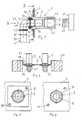
- the line bushing 1 shown in FIG. 1 has a connection fitting 3 on, in particular a turned part made of brass and which has a connecting part 10 at a first end 21 a line L and at a second end 22 with a sanitary fitting A is to be connected.
- the connection fitting 3 carries out through a wall 2, for example a connection plate which is attached to a sanitary rack 20 according to FIG is. Two or more than two such cable bushings 1 may be installed.
- connection fitting 3 has a cylindrical outside 23 a polygonal outer contour 4, in particular hexagonal is and the anti-rotation in a corresponding opening 8 is used.
- the polygonal outer contour 4 is designed that they are either from one side or the other can be used in the breakthrough 8.
- the fitting 3 can in Figure 1 thus used either from the left or from the right become.
- a groove 11 is machined into the polygonal outer contour 4, provided for receiving a mounting plate 7 , which also has an opening 9, which corresponds formed to polygonal outer contour 4 and thus is particularly hexagonal. Is the connection fitting 3 in the Breakthrough 8 used, the mounting plate according to Figure 1 7 placed on the polygonal outer contour 4 from the left and twisted by half a polygon, so that the breakthroughs 8 and 9 are arranged according to Figure 3.
- connection fitting 3 is thus axially fixed to the holding plate 7.
- the wall 2 has two mounting holes arranged diametrically to the opening 8 17, with the mounting plate 7 with mounting holes 18 of the holding plate 7 are in cover.
- fastening elements 19 for example fastening screws or rivets or the like attached.
- the connection fitting 3 is thus firmly connected to the plate 2.
- the Connection fitting 3 can no longer be rotated about its longitudinal axis 23 and can no longer be moved in the axial direction.
- connection fitting 3 has second end 22 has an internal thread 6, in which the valve A with an external thread 24 is screwed. But there are other fasteners are also conceivable.
- the connection fitting 3 can be very inexpensive from a polygonal bar stock getting produced. External threads are not required.
- the line part 10 which according to FIG. 1 in particular is a 90 ° elbow, is at the first end 21 Connector 12 provided.
- the ring 13 is an expansion ring, for example can be made of plastic.
- the line part 10 has two peripheral outer flanges 15, one of which is in the ring 13 is engaged. With line part 10 in place the ring 13 comprises the corresponding flange 15 and fixed this axially.
- a sealing ring 16 is arranged, the 1 in a passage 5 of the connection fittings 13 Seals connector 10 against connector fitting 3.
- FIG. 1 is a 90 ° elbow
- the plug connection 12 enables the line part to be rotated 10 about the axis 23.
- the line part 10 can thus be arbitrary aligned and thus to the pipe to be connected be adjusted.
- connection fitting 3 On the connection fitting 3, the holding plate 7 is explained as above placed.
- the connection fitting is now shown in FIG 3 with the mounting plate 7 from the left in the Breakthrough 8 inserted until the holding plate 7 on the back against the wall. With the fasteners 19, the fitting 3 attached to the wall 2.
- the line part 10 in of Figure 1 from the left on the first end 21 until the Flange 15 is engaged in the ring 13.
- the connector 10 is now rotated about the longitudinal axis 23 until it is the one for the connection a line not shown exactly aligned is.
- This line is now placed on the line part 10 and fixed with the flange 15 'and with the sealing ring 16'abgeêt.
- connection fitting 3 can also be used without a holding plate 7 are used in the breakthrough 8.
- the holding plate 7 is then placed on the fitting 3 and as above mentioned rotated.
- connection fitting 3 can be on the wall 2 or on the connection plate be pre-assembled and then forms a structural unit that on Installation location only attached to the sanitary rack 20 must become.
- a structural unit can have two or have more than two line bushings 1.
- the said The structural unit thus comprises at least one wall 2 or connection plate, at least one fitting 3, a holding plate 7 and a retaining ring 13. Basically, this unit also have at least one line part 10, which already 1 is inserted into the connection fitting 3. With a Such pre-assembled unit can work on the installation site be significantly simplified. It just has to still the connection plate 2 on the assembly frame and the conduit to be attached to the line part 10.
Abstract
Description
- Figur 1
- ein Schnitt durch eine montierte erfindungsgemässe Leitungsdurchführung,
- Figur 2
- eine Ansicht von zwei Leitungsdurchführungen, die an einem Montagegestelle installiert sind,
- Figur 3
- eine Ansicht gemäss dem Pfeil III der Figur 1, wobei der Leitungsteil weggelassen ist und
- Figur 4
- ein Schnitt entlang der Linie IV-IV der Figur 1.
- 1
- Leitungsdurchführung
- 2
- Anschlussplatte
- 3
- Anschlussfitting
- 4
- Mehrkant-Aussenkontur
- 5
- Durchgang
- 6
- Innengewinde
- 7
- Befestigungsplatte
- 8
- Durchbruch
- 9
- Durchbruch
- 10
- Leitungsteil
- 11
- Nut
- 12
- Steckverbindung
- 13
- Ring
- 14
- Ausnehmung
- 15
- Flansch
- 16
- Dichtungsring
- 17
- Befestigungsloch
- 18
- Befestigungsloch
- 19
- Befestigungselement
- 20
- Gestell
- 21
- erstes Ende
- 22
- zweites Ende
- 23
- Längsachse
- 24
- Aussengewinde
- 25
- Aussenseite
Claims (7)
- Leitungsdurchführung für die Installation von durch Wände (2) hindurchführenden Sanitärleitungen (L), mit einem Anschlussfitting (3), der ein erstes (21) und ein zweites Ende (22), eine Mehrkant-Aussenkontur (4) sowie einen Durchgang (5) aufweist, dadurch gekennzeichnet, dass der Anschlussfitting (3) am ersten Ende (21) Verbindungsmittel (13, 14) zur Herstellung einer Steckverbindung (12) aufweist.
- Leitungsdurchführung nach Anspruch 1, dadurch gekennzeichnet, dass eine um die Längsachse (23) drehbare Steckverbindung herstellbar ist.
- Leitungsdurchführung nach Anspruch 1 oder 2, dadurch gekennzeichnet, dass die Verbindungsmittel (13, 14) einen Haltering (13) aufweisen, der in eine ringförmige Ausnehmung (14) des ersten Endes (21) eingesetzt ist und der zur Aufnahme eines Flansches (15) eines Leitungsteils (10) ausgebildet ist.
- Leitungsdurchführung nach einem der Ansprüche 1 bis 3, dadurch gekennzeichnet, dass in die Mehrkant-Aussenkontur (4) eine Nut (11) eingearbeitet ist, in die eine Befestigungsplatte (7) eingedreht ist, wobei diese Befestigungsplatte (7) einen Durchbruch (9) aufweist, der vorzugsweise korrespondierend zur Mehrfach-Aussenkontur (4) ausgebildet ist.
- Leitungsdurchführung nach einem der Ansprüche 1 bis 4, dadurch gekennzeichnet, dass der Anschlussfitting (3) eine gewindefreie Aussenseite (25) aufweist.
- Leitungsdurchführung nach einem der Ansprüche 1 bis 5, dadurch gekennzeichnet, dass der Anschlussfitting (3) als Drehteil aus einem mehrkantigen Stangenmaterial hergestellt ist.
- Leitungsdurchführung nach einem der Ansprüche 1 bis 6, dadurch gekennzeichnet, dass der Anschlussfitting (3) mit einer Halteplatte (7) und Verbindungsmitteln (13, 14) eine vormontierte Baueinheit bildet.
Priority Applications (4)
| Application Number | Priority Date | Filing Date | Title |
|---|---|---|---|
| EP03405402A EP1484544B1 (de) | 2003-06-03 | 2003-06-03 | Leitungsdurchführung für die Installation von einer durch eine Wand hindurchführende Sanitärleitung |
| DE50313310T DE50313310D1 (de) | 2003-06-03 | 2003-06-03 | Leitungsdurchführung für die Installation von einer durch eine Wand hindurchführende Sanitärleitung |
| AT03405402T ATE491112T1 (de) | 2003-06-03 | 2003-06-03 | Leitungsdurchführung für die installation von einer durch eine wand hindurchführende sanitärleitung |
| PL368221A PL204508B1 (pl) | 2003-06-03 | 2004-05-27 | Przepust do instalacji przewodu urządzenia sanitarnego |
Applications Claiming Priority (1)
| Application Number | Priority Date | Filing Date | Title |
|---|---|---|---|
| EP03405402A EP1484544B1 (de) | 2003-06-03 | 2003-06-03 | Leitungsdurchführung für die Installation von einer durch eine Wand hindurchführende Sanitärleitung |
Publications (2)
| Publication Number | Publication Date |
|---|---|
| EP1484544A1 true EP1484544A1 (de) | 2004-12-08 |
| EP1484544B1 EP1484544B1 (de) | 2010-12-08 |
Family
ID=33155293
Family Applications (1)
| Application Number | Title | Priority Date | Filing Date |
|---|---|---|---|
| EP03405402A Expired - Lifetime EP1484544B1 (de) | 2003-06-03 | 2003-06-03 | Leitungsdurchführung für die Installation von einer durch eine Wand hindurchführende Sanitärleitung |
Country Status (4)
| Country | Link |
|---|---|
| EP (1) | EP1484544B1 (de) |
| AT (1) | ATE491112T1 (de) |
| DE (1) | DE50313310D1 (de) |
| PL (1) | PL204508B1 (de) |
Cited By (7)
| Publication number | Priority date | Publication date | Assignee | Title |
|---|---|---|---|---|
| DE102004023242A1 (de) * | 2004-05-07 | 2005-12-01 | Airbus Deutschland Gmbh | Anschlußelement zum Verbinden eines Leitungssystems mit Kühlaggregaten in Flugzeugkabinen |
| US7934753B2 (en) | 2004-05-07 | 2011-05-03 | Airbus Deutschland Gmbh | Aircraft with connection element for connecting a conduit system to cooling aggregates in aircraft cabins |
| EP2503203A1 (de) | 2011-03-21 | 2012-09-26 | Geberit International AG | Armaturenanschluss |
| FR3017922A1 (fr) * | 2014-02-25 | 2015-08-28 | Comap | Systeme de raccordement d’un robinet sur une paroi |
| DE102018103649A1 (de) * | 2018-02-19 | 2019-08-22 | Viega Technology Gmbh & Co. Kg | Sanitärwandmodul und Verfahren zum Errichten einer Sanitärwand |
| EP4194625A1 (de) * | 2021-12-09 | 2023-06-14 | Geberit International AG | Rohranschlussanordnung |
| WO2023199150A1 (en) * | 2022-04-14 | 2023-10-19 | I.V.A.R. S.P.A. | Connector for connecting a duct for circulating a fluid to a utility and related fixing system |
Families Citing this family (1)
| Publication number | Priority date | Publication date | Assignee | Title |
|---|---|---|---|---|
| DE102020130199A1 (de) * | 2020-11-16 | 2022-05-19 | Grohe Ag | Vorrichtung zur Befestigung einer Sanitäreinrichtung an einer Wand und Sanitärinstallation mit einer entsprechenden Vorrichtung |
Citations (12)
| Publication number | Priority date | Publication date | Assignee | Title |
|---|---|---|---|---|
| US1587079A (en) | 1923-08-15 | 1926-06-01 | Shuichi Katakura | Hose coupling |
| GB926215A (en) | 1960-11-09 | 1963-05-15 | Rollmaplast Ag | Disengageable pipe coupling |
| DE1800399A1 (de) * | 1968-10-01 | 1970-05-21 | Leo Larikka | Anordnung bei Rohrverlegungen in Gebaeuden |
| US4989278A (en) * | 1989-03-09 | 1991-02-05 | Friedrich Grohe Armaturenfabrik Gmbh & Co. | Wall-mount faucet with accessory-holding bracket |
| DE29805720U1 (de) | 1998-03-28 | 1999-08-05 | Voss Armaturen | Steckkupplung für Druckmittelsysteme |
| DE19757975C1 (de) * | 1997-12-24 | 1999-09-23 | Schell Gmbh & Co Kg | Wandanschluß für Armaturen |
| US6027144A (en) | 1996-09-20 | 2000-02-22 | Armaturenfabrik Hermann Voss Gmbh + Co. | Plug-in connector for pressure medium systems |
| DE29922692U1 (de) | 1999-02-02 | 2000-03-09 | Geberit Technik Ag | Steckverbindung mit einem hohlzylindrischen Aufnahmeteil |
| DE10039981A1 (de) | 2000-08-16 | 2002-03-07 | Dieter John | Montageelement für die Wandmontage eines Kupplungselementes zum Verbinden von Fluidleitungen |
| US20020038955A1 (en) * | 2000-10-03 | 2002-04-04 | Eaton Aeroquip, Inc. | Coupling adapter and assembly |
| EP1235023A1 (de) | 2001-02-15 | 2002-08-28 | Eaton Aeroquip, Inc. | Kupplungsvorrichtung |
| DE20209791U1 (de) * | 2002-06-24 | 2002-10-17 | Herbert Burda Gmbh | Anschlussarmatur für einen Spülkasten |
-
2003
- 2003-06-03 EP EP03405402A patent/EP1484544B1/de not_active Expired - Lifetime
- 2003-06-03 AT AT03405402T patent/ATE491112T1/de active
- 2003-06-03 DE DE50313310T patent/DE50313310D1/de not_active Expired - Lifetime
-
2004
- 2004-05-27 PL PL368221A patent/PL204508B1/pl unknown
Patent Citations (13)
| Publication number | Priority date | Publication date | Assignee | Title |
|---|---|---|---|---|
| US1587079A (en) | 1923-08-15 | 1926-06-01 | Shuichi Katakura | Hose coupling |
| GB926215A (en) | 1960-11-09 | 1963-05-15 | Rollmaplast Ag | Disengageable pipe coupling |
| DE1800399A1 (de) * | 1968-10-01 | 1970-05-21 | Leo Larikka | Anordnung bei Rohrverlegungen in Gebaeuden |
| US4989278A (en) * | 1989-03-09 | 1991-02-05 | Friedrich Grohe Armaturenfabrik Gmbh & Co. | Wall-mount faucet with accessory-holding bracket |
| US6027144A (en) | 1996-09-20 | 2000-02-22 | Armaturenfabrik Hermann Voss Gmbh + Co. | Plug-in connector for pressure medium systems |
| DE19757975C1 (de) * | 1997-12-24 | 1999-09-23 | Schell Gmbh & Co Kg | Wandanschluß für Armaturen |
| DE29805720U1 (de) | 1998-03-28 | 1999-08-05 | Voss Armaturen | Steckkupplung für Druckmittelsysteme |
| US6305721B1 (en) * | 1998-03-28 | 2001-10-23 | Armaturenfabrik Hermann Voss Gmbh & Co | Plug-in coupling for pressure application systems |
| DE29922692U1 (de) | 1999-02-02 | 2000-03-09 | Geberit Technik Ag | Steckverbindung mit einem hohlzylindrischen Aufnahmeteil |
| DE10039981A1 (de) | 2000-08-16 | 2002-03-07 | Dieter John | Montageelement für die Wandmontage eines Kupplungselementes zum Verbinden von Fluidleitungen |
| US20020038955A1 (en) * | 2000-10-03 | 2002-04-04 | Eaton Aeroquip, Inc. | Coupling adapter and assembly |
| EP1235023A1 (de) | 2001-02-15 | 2002-08-28 | Eaton Aeroquip, Inc. | Kupplungsvorrichtung |
| DE20209791U1 (de) * | 2002-06-24 | 2002-10-17 | Herbert Burda Gmbh | Anschlussarmatur für einen Spülkasten |
Cited By (8)
| Publication number | Priority date | Publication date | Assignee | Title |
|---|---|---|---|---|
| DE102004023242A1 (de) * | 2004-05-07 | 2005-12-01 | Airbus Deutschland Gmbh | Anschlußelement zum Verbinden eines Leitungssystems mit Kühlaggregaten in Flugzeugkabinen |
| DE102004023242B4 (de) * | 2004-05-07 | 2007-06-14 | Airbus Deutschland Gmbh | Anschlußelement zum Verbinden von zwei Leitungselementen eines durch ein Trennelement zur Kabine eines Flugzeugs geführten Leitungssystems |
| US7934753B2 (en) | 2004-05-07 | 2011-05-03 | Airbus Deutschland Gmbh | Aircraft with connection element for connecting a conduit system to cooling aggregates in aircraft cabins |
| EP2503203A1 (de) | 2011-03-21 | 2012-09-26 | Geberit International AG | Armaturenanschluss |
| FR3017922A1 (fr) * | 2014-02-25 | 2015-08-28 | Comap | Systeme de raccordement d’un robinet sur une paroi |
| DE102018103649A1 (de) * | 2018-02-19 | 2019-08-22 | Viega Technology Gmbh & Co. Kg | Sanitärwandmodul und Verfahren zum Errichten einer Sanitärwand |
| EP4194625A1 (de) * | 2021-12-09 | 2023-06-14 | Geberit International AG | Rohranschlussanordnung |
| WO2023199150A1 (en) * | 2022-04-14 | 2023-10-19 | I.V.A.R. S.P.A. | Connector for connecting a duct for circulating a fluid to a utility and related fixing system |
Also Published As
| Publication number | Publication date |
|---|---|
| DE50313310D1 (de) | 2011-01-20 |
| PL368221A1 (en) | 2004-12-13 |
| EP1484544B1 (de) | 2010-12-08 |
| PL204508B1 (pl) | 2010-01-29 |
| ATE491112T1 (de) | 2010-12-15 |
Similar Documents
| Publication | Publication Date | Title |
|---|---|---|
| DE10233127C1 (de) | Vorrichtung zur Wanddurchführung von Rohrleitungen, Schläuchen oder elektrischen Kabeln für Kraftfahrzeuge | |
| AT3080U1 (de) | Vorrichtung zum verbinden eines rohrstutzens, rohrförmigen armaturenteils oder fittings mit einem rohr | |
| EP2778298B1 (de) | Sanitärarmaturen-Anschlusssystem | |
| DE602005004621T2 (de) | Messsensor | |
| EP1484544A1 (de) | Leitungsdurchführung für die Installation von einer durch eine Wand hindurchführende Sanitärleitung | |
| DE102012204872A1 (de) | Anordnung mit einstellbarem Kompressionslastbegrenzer | |
| EP0538197B1 (de) | Einrichtung als Verbindung zwischen einer flexiblen unter Putz verlegten Rohrleitung und einer über Putz anzuordnenden Armatur (flexibler Dosenhals) | |
| EP0733745A2 (de) | Befestigungsanordnung mit einem Installationselement | |
| EP2251495B1 (de) | Wasseranschlussanordnung mit einem Anschlussstück für eine vereinfachte Montage einer Anschlusseinrichtung, insbesondere eines Wasserbehandlungsgeräts | |
| AT400977B (de) | Anordnung zum befestigen von rohren | |
| EP2226430A1 (de) | Anschlusseinrichtung für Auslaufarmaturen | |
| EP3492796B1 (de) | Verbindungssystem zur reparatur von kunststoffverbundrohrsystemen | |
| EP3366851A1 (de) | Universal-füllventil-set | |
| DE102012201693B4 (de) | Adapterelement | |
| DE202017105688U1 (de) | Elektronisches Bauteil | |
| DE102008046658B4 (de) | Kabeldurchführung | |
| DE102017123765A1 (de) | Adapter zum Anschluss einer Ventil- oder Spülarmatur an eine Rohrleitung und System mit einem solchen Adapter und einem Vorwandgestellelement | |
| CH692514A5 (de) | Vorrichtung zur dichtenden Einführung eines Rohres in ein Gebäude. | |
| EP1816382B1 (de) | Wanddurchführung | |
| DE202009017485U1 (de) | Soleverteiler für Erdwärmesonden | |
| DE102015010837A1 (de) | Verbindungsbauteil und Gerät mit einem Verbindungsbauteil | |
| DE10230804A1 (de) | Flanschelement | |
| DE102010017440A1 (de) | Kabeldurchführung für einen Durchbruch in einer Wandung | |
| EP3715690A1 (de) | Adapter für schlauchverschraubungen | |
| EP3517793A1 (de) | Rohrverbindungsvorrichtung |
Legal Events
| Date | Code | Title | Description |
|---|---|---|---|
| PUAI | Public reference made under article 153(3) epc to a published international application that has entered the european phase |
Free format text: ORIGINAL CODE: 0009012 |
|
| AK | Designated contracting states |
Kind code of ref document: A1 Designated state(s): AT BE BG CH CY CZ DE DK EE ES FI FR GB GR HU IE IT LI LU MC NL PT RO SE SI SK TR |
|
| AX | Request for extension of the european patent |
Extension state: AL LT LV MK |
|
| 17P | Request for examination filed |
Effective date: 20050112 |
|
| 17Q | First examination report despatched |
Effective date: 20050221 |
|
| AKX | Designation fees paid |
Designated state(s): AT BE BG CH CY CZ DE DK EE ES FI FR GB GR HU IE IT LI LU MC NL PT RO SE SI SK TR |
|
| APBN | Date of receipt of notice of appeal recorded |
Free format text: ORIGINAL CODE: EPIDOSNNOA2E |
|
| APAF | Appeal reference modified |
Free format text: ORIGINAL CODE: EPIDOSCREFNE |
|
| APBR | Date of receipt of statement of grounds of appeal recorded |
Free format text: ORIGINAL CODE: EPIDOSNNOA3E |
|
| APAF | Appeal reference modified |
Free format text: ORIGINAL CODE: EPIDOSCREFNE |
|
| APBT | Appeal procedure closed |
Free format text: ORIGINAL CODE: EPIDOSNNOA9E |
|
| GRAP | Despatch of communication of intention to grant a patent |
Free format text: ORIGINAL CODE: EPIDOSNIGR1 |
|
| RAP1 | Party data changed (applicant data changed or rights of an application transferred) |
Owner name: GEBERIT INTERNATIONAL AG |
|
| GRAS | Grant fee paid |
Free format text: ORIGINAL CODE: EPIDOSNIGR3 |
|
| GRAA | (expected) grant |
Free format text: ORIGINAL CODE: 0009210 |
|
| AK | Designated contracting states |
Kind code of ref document: B1 Designated state(s): AT BE BG CH CY CZ DE DK EE ES FI FR GB GR HU IE IT LI LU MC NL PT RO SE SI SK TR |
|
| REG | Reference to a national code |
Ref country code: GB Ref legal event code: FG4D Free format text: NOT ENGLISH |
|
| REG | Reference to a national code |
Ref country code: CH Ref legal event code: EP Ref country code: CH Ref legal event code: NV Representative=s name: ISLER & PEDRAZZINI AG |
|
| REG | Reference to a national code |
Ref country code: IE Ref legal event code: FG4D |
|
| REF | Corresponds to: |
Ref document number: 50313310 Country of ref document: DE Date of ref document: 20110120 Kind code of ref document: P |
|
| REG | Reference to a national code |
Ref country code: NL Ref legal event code: VDEP Effective date: 20101208 |
|
| PG25 | Lapsed in a contracting state [announced via postgrant information from national office to epo] |
Ref country code: BG Free format text: LAPSE BECAUSE OF FAILURE TO SUBMIT A TRANSLATION OF THE DESCRIPTION OR TO PAY THE FEE WITHIN THE PRESCRIBED TIME-LIMIT Effective date: 20110308 Ref country code: CY Free format text: LAPSE BECAUSE OF FAILURE TO SUBMIT A TRANSLATION OF THE DESCRIPTION OR TO PAY THE FEE WITHIN THE PRESCRIBED TIME-LIMIT Effective date: 20101208 Ref country code: FI Free format text: LAPSE BECAUSE OF FAILURE TO SUBMIT A TRANSLATION OF THE DESCRIPTION OR TO PAY THE FEE WITHIN THE PRESCRIBED TIME-LIMIT Effective date: 20101208 Ref country code: SI Free format text: LAPSE BECAUSE OF FAILURE TO SUBMIT A TRANSLATION OF THE DESCRIPTION OR TO PAY THE FEE WITHIN THE PRESCRIBED TIME-LIMIT Effective date: 20101208 Ref country code: SE Free format text: LAPSE BECAUSE OF FAILURE TO SUBMIT A TRANSLATION OF THE DESCRIPTION OR TO PAY THE FEE WITHIN THE PRESCRIBED TIME-LIMIT Effective date: 20101208 Ref country code: NL Free format text: LAPSE BECAUSE OF FAILURE TO SUBMIT A TRANSLATION OF THE DESCRIPTION OR TO PAY THE FEE WITHIN THE PRESCRIBED TIME-LIMIT Effective date: 20101208 |
|
| REG | Reference to a national code |
Ref country code: IE Ref legal event code: FD4D |
|
| PG25 | Lapsed in a contracting state [announced via postgrant information from national office to epo] |
Ref country code: ES Free format text: LAPSE BECAUSE OF FAILURE TO SUBMIT A TRANSLATION OF THE DESCRIPTION OR TO PAY THE FEE WITHIN THE PRESCRIBED TIME-LIMIT Effective date: 20110319 Ref country code: EE Free format text: LAPSE BECAUSE OF FAILURE TO SUBMIT A TRANSLATION OF THE DESCRIPTION OR TO PAY THE FEE WITHIN THE PRESCRIBED TIME-LIMIT Effective date: 20101208 Ref country code: GR Free format text: LAPSE BECAUSE OF FAILURE TO SUBMIT A TRANSLATION OF THE DESCRIPTION OR TO PAY THE FEE WITHIN THE PRESCRIBED TIME-LIMIT Effective date: 20110309 Ref country code: PT Free format text: LAPSE BECAUSE OF FAILURE TO SUBMIT A TRANSLATION OF THE DESCRIPTION OR TO PAY THE FEE WITHIN THE PRESCRIBED TIME-LIMIT Effective date: 20110408 Ref country code: IE Free format text: LAPSE BECAUSE OF FAILURE TO SUBMIT A TRANSLATION OF THE DESCRIPTION OR TO PAY THE FEE WITHIN THE PRESCRIBED TIME-LIMIT Effective date: 20101208 Ref country code: CZ Free format text: LAPSE BECAUSE OF FAILURE TO SUBMIT A TRANSLATION OF THE DESCRIPTION OR TO PAY THE FEE WITHIN THE PRESCRIBED TIME-LIMIT Effective date: 20101208 |
|
| PG25 | Lapsed in a contracting state [announced via postgrant information from national office to epo] |
Ref country code: SK Free format text: LAPSE BECAUSE OF FAILURE TO SUBMIT A TRANSLATION OF THE DESCRIPTION OR TO PAY THE FEE WITHIN THE PRESCRIBED TIME-LIMIT Effective date: 20101208 Ref country code: RO Free format text: LAPSE BECAUSE OF FAILURE TO SUBMIT A TRANSLATION OF THE DESCRIPTION OR TO PAY THE FEE WITHIN THE PRESCRIBED TIME-LIMIT Effective date: 20101208 |
|
| PLBE | No opposition filed within time limit |
Free format text: ORIGINAL CODE: 0009261 |
|
| STAA | Information on the status of an ep patent application or granted ep patent |
Free format text: STATUS: NO OPPOSITION FILED WITHIN TIME LIMIT |
|
| PG25 | Lapsed in a contracting state [announced via postgrant information from national office to epo] |
Ref country code: DK Free format text: LAPSE BECAUSE OF FAILURE TO SUBMIT A TRANSLATION OF THE DESCRIPTION OR TO PAY THE FEE WITHIN THE PRESCRIBED TIME-LIMIT Effective date: 20101208 |
|
| 26N | No opposition filed |
Effective date: 20110909 |
|
| REG | Reference to a national code |
Ref country code: DE Ref legal event code: R097 Ref document number: 50313310 Country of ref document: DE Effective date: 20110909 |
|
| GBPC | Gb: european patent ceased through non-payment of renewal fee |
Effective date: 20110603 |
|
| REG | Reference to a national code |
Ref country code: FR Ref legal event code: ST Effective date: 20120229 |
|
| PG25 | Lapsed in a contracting state [announced via postgrant information from national office to epo] |
Ref country code: FR Free format text: LAPSE BECAUSE OF NON-PAYMENT OF DUE FEES Effective date: 20110630 |
|
| PG25 | Lapsed in a contracting state [announced via postgrant information from national office to epo] |
Ref country code: GB Free format text: LAPSE BECAUSE OF NON-PAYMENT OF DUE FEES Effective date: 20110603 |
|
| PG25 | Lapsed in a contracting state [announced via postgrant information from national office to epo] |
Ref country code: MC Free format text: LAPSE BECAUSE OF NON-PAYMENT OF DUE FEES Effective date: 20110630 |
|
| PG25 | Lapsed in a contracting state [announced via postgrant information from national office to epo] |
Ref country code: LU Free format text: LAPSE BECAUSE OF NON-PAYMENT OF DUE FEES Effective date: 20110603 |
|
| REG | Reference to a national code |
Ref country code: DE Ref legal event code: R082 Ref document number: 50313310 Country of ref document: DE Representative=s name: HOEGER, STELLRECHT & PARTNER PATENTANWAELTE, DE Ref country code: DE Ref legal event code: R082 Ref document number: 50313310 Country of ref document: DE Representative=s name: HOEGER, STELLRECHT & PARTNER PATENTANWAELTE MB, DE |
|
| PG25 | Lapsed in a contracting state [announced via postgrant information from national office to epo] |
Ref country code: TR Free format text: LAPSE BECAUSE OF FAILURE TO SUBMIT A TRANSLATION OF THE DESCRIPTION OR TO PAY THE FEE WITHIN THE PRESCRIBED TIME-LIMIT Effective date: 20101208 |
|
| PG25 | Lapsed in a contracting state [announced via postgrant information from national office to epo] |
Ref country code: HU Free format text: LAPSE BECAUSE OF FAILURE TO SUBMIT A TRANSLATION OF THE DESCRIPTION OR TO PAY THE FEE WITHIN THE PRESCRIBED TIME-LIMIT Effective date: 20101208 |
|
| PGFP | Annual fee paid to national office [announced via postgrant information from national office to epo] |
Ref country code: BE Payment date: 20140620 Year of fee payment: 12 |
|
| PGFP | Annual fee paid to national office [announced via postgrant information from national office to epo] |
Ref country code: IT Payment date: 20140630 Year of fee payment: 12 |
|
| REG | Reference to a national code |
Ref country code: DE Ref legal event code: R082 Ref document number: 50313310 Country of ref document: DE Representative=s name: HOEGER, STELLRECHT & PARTNER PATENTANWAELTE MB, DE |
|
| PG25 | Lapsed in a contracting state [announced via postgrant information from national office to epo] |
Ref country code: IT Free format text: LAPSE BECAUSE OF NON-PAYMENT OF DUE FEES Effective date: 20150603 |
|
| PGFP | Annual fee paid to national office [announced via postgrant information from national office to epo] |
Ref country code: CH Payment date: 20160613 Year of fee payment: 14 |
|
| PGFP | Annual fee paid to national office [announced via postgrant information from national office to epo] |
Ref country code: AT Payment date: 20160621 Year of fee payment: 14 |
|
| PG25 | Lapsed in a contracting state [announced via postgrant information from national office to epo] |
Ref country code: BE Free format text: LAPSE BECAUSE OF NON-PAYMENT OF DUE FEES Effective date: 20150630 |
|
| REG | Reference to a national code |
Ref country code: CH Ref legal event code: PL |
|
| REG | Reference to a national code |
Ref country code: AT Ref legal event code: MM01 Ref document number: 491112 Country of ref document: AT Kind code of ref document: T Effective date: 20170603 |
|
| PG25 | Lapsed in a contracting state [announced via postgrant information from national office to epo] |
Ref country code: CH Free format text: LAPSE BECAUSE OF NON-PAYMENT OF DUE FEES Effective date: 20170630 Ref country code: LI Free format text: LAPSE BECAUSE OF NON-PAYMENT OF DUE FEES Effective date: 20170630 |
|
| PG25 | Lapsed in a contracting state [announced via postgrant information from national office to epo] |
Ref country code: AT Free format text: LAPSE BECAUSE OF NON-PAYMENT OF DUE FEES Effective date: 20170603 |
|
| REG | Reference to a national code |
Ref country code: DE Ref legal event code: R082 Ref document number: 50313310 Country of ref document: DE Representative=s name: HOEGER, STELLRECHT & PARTNER PATENTANWAELTE MB, DE |
|
| PGFP | Annual fee paid to national office [announced via postgrant information from national office to epo] |
Ref country code: DE Payment date: 20200618 Year of fee payment: 18 |
|
| REG | Reference to a national code |
Ref country code: DE Ref legal event code: R119 Ref document number: 50313310 Country of ref document: DE |
|
| PG25 | Lapsed in a contracting state [announced via postgrant information from national office to epo] |
Ref country code: DE Free format text: LAPSE BECAUSE OF NON-PAYMENT OF DUE FEES Effective date: 20220101 |