EP1484443B1 - Vorrichtung und Verfahren zum Regeln der Spannkraft einer laufenden Bahn - Google Patents
Vorrichtung und Verfahren zum Regeln der Spannkraft einer laufenden Bahn Download PDFInfo
- Publication number
- EP1484443B1 EP1484443B1 EP04012854A EP04012854A EP1484443B1 EP 1484443 B1 EP1484443 B1 EP 1484443B1 EP 04012854 A EP04012854 A EP 04012854A EP 04012854 A EP04012854 A EP 04012854A EP 1484443 B1 EP1484443 B1 EP 1484443B1
- Authority
- EP
- European Patent Office
- Prior art keywords
- force
- tension
- measuring roll
- roll
- web
- Prior art date
- Legal status (The legal status is an assumption and is not a legal conclusion. Google has not performed a legal analysis and makes no representation as to the accuracy of the status listed.)
- Expired - Lifetime
Links
- 238000000034 method Methods 0.000 title claims description 12
- 230000001105 regulatory effect Effects 0.000 claims description 14
- 238000003860 storage Methods 0.000 claims description 4
- 239000011248 coating agent Substances 0.000 claims description 3
- 238000000576 coating method Methods 0.000 claims description 3
- 230000001419 dependent effect Effects 0.000 claims 3
- 239000004744 fabric Substances 0.000 claims 2
- 230000001276 controlling effect Effects 0.000 description 4
- 238000006073 displacement reaction Methods 0.000 description 4
- 238000001514 detection method Methods 0.000 description 3
- 230000000694 effects Effects 0.000 description 3
- 239000002245 particle Substances 0.000 description 3
- 230000007547 defect Effects 0.000 description 2
- 238000005259 measurement Methods 0.000 description 2
- XLYOFNOQVPJJNP-UHFFFAOYSA-N water Substances O XLYOFNOQVPJJNP-UHFFFAOYSA-N 0.000 description 2
- 230000002349 favourable effect Effects 0.000 description 1
- 238000004519 manufacturing process Methods 0.000 description 1
- 238000003825 pressing Methods 0.000 description 1
- 238000004804 winding Methods 0.000 description 1
Images

Classifications
-
- D—TEXTILES; PAPER
- D21—PAPER-MAKING; PRODUCTION OF CELLULOSE
- D21F—PAPER-MAKING MACHINES; METHODS OF PRODUCING PAPER THEREON
- D21F7/00—Other details of machines for making continuous webs of paper
- D21F7/005—Wire-tensioning devices
Definitions
- the invention relates to a device for regulating the tension of a moving web according to the preamble of patent claim 1 and a method according to the preamble of patent claim 8.
- circulating filter belts for dewatering paper webs are known.
- the paper web is pressed against the wire to press water out of the paper web.
- the rotating belt is designed as an endless belt and runs at the same speed as the paper web.
- it is important that the circulating belt is subjected to a given tension within certain tolerances. This is effected by controlling the tape tensile force, wherein one of the rollers serves as a force measuring roller for determining the belt tensile force and one is designed as a tension control roller.
- the force measuring roller has in each case at both opposing bearings on a force sensor which measures the bearing force.
- the tension control roller is adjusted by a servomotor to more or less tension the circulating belt.
- the force sensors are operatively connected via a control device to the tension control roller.
- the circulating belt on the force measuring roller is deflected by 180 °.
- the force measuring roller is looped around, regardless of the position of the actuator in always the same way, so that the measured bearing force directly reflects the tape tension. Due to the large loop of the force measuring roller, it is necessary to detect the tape both inside and outside of rollers. Thus, the paper-contacting side of the circulating belt is detected by rollers, so that can cumulate on these rollers particles from the paper web. These particles lead to defects in the paper web and are therefore undesirable.
- the invention has for its object to provide an apparatus and a method for controlling the tension of a moving web, which allows for low-umgeschlingung the force measuring roller precise control of the belt tension.
- the device according to claim 1 serves to regulate the tension of a moving web, in particular a circulating belt, in particular to a felt or wire belt of a pulp or papermaking machine or a coating machine is intended. It is advantageous if the circulating belt is deflected by as few rolls as possible, which should capture the circulating belt as possible only from the side not touched paper. However, this can only be done if the circulating belt is deflected by each roller by less than 180 °. For a smooth operation, it is also necessary to keep the clamping force of the circulating belt constant, which is done by a clamping force control device. This is influenced by at least one force sensor of a Kraftmeßwalze, on which the circulating belt is deflected.
- the determined bearing force is a measure of the belt tension.
- the control device acts on an actuator of an adjustable tension control roller, which controls this according to the output signal of the control device. This results in the problem that results in an adjustment of the tension control roller an altered wrap of Kraftmeßwalze. Under these conditions, the bearing force gives no clear value for the belt tension, so that the circulating belt is regulated depending on the position of the tension control roller to different belt tensions.
- the force sensor is associated with a correction device which takes into account the wrap of the force measuring roller. This correction device calculates the tape tension from the bearing force and the wrapping of the force measuring roller and forwards them to the control device as the actual value.
- control device regulates the belt tension to a constant value, regardless of the position of the tensioning roller and thus independent of the resulting looping of the circulating belt.
- This ensures a constant production quality in all operating conditions. In particular, it does not matter if the tape is incorrectly deflected, especially as the resulting value of the wrap around the force measuring roll is taken into account in determining the tape tensile force.
- the correction device is influenced by the position of the tension control roller and thus by the respective position of the actuator.
- This position can be detected directly by a displacement sensor, which is connected for example to a drive shaft of the actuator.
- the displacement sensor determines the distance traveled by the actuator, so that the respective position of the tension control roller is known in any operating condition.
- the actuator is preferably assigned at least one limit switch, which ensures a zero point setting of the position detection.
- the correction device is influenced by the relative position of the force measuring roller to the adjacent rollers.
- the correction device is associated with a storage device in which the layers of the fixed rollers are stored. It is quite sufficient to store the layers of those rolls, which are adjacent to the force measuring roller, since the other rollers have no influence on the wrap of Kraftmeßwalze. From the known positions of the force measuring roller adjacent rollers and the force measuring roller itself, the wrap of the force measuring roller and thus the required correction factor for calculating the strip tension can be easily determined.
- the correction device when the correction device is influenced by at least two force sensors of the force measuring roller.
- These force sensors act in different directions, so that the bearing force of the force measuring roller is vectorially detected by these. From this vectorial bearing force, in addition to the amount of the bearing force, its direction can also be determined, from which the wrap of the force measuring roll can be determined. In particular, it is not necessary to know the exact positions of the adjacent rolls, so that structural changes of the roll structure remain without effect on the measurement result.
- a pivotable web guide roller is basically provided by means of which the circulating belt is guided.
- the tensioning roller and the Kraftmeßwalze are formed by the same roller.
- the force measuring roller is adjusted by the actuator, resulting in a relatively large change in the wrap by the rotating belt.
- this changing loop is sufficiently taken into account by the correction device in order to achieve a reliable clamping force control.
- a moving web in particular a circulating belt of rolls is deflected.
- At least one of the rollers is designed as a force measuring roller whose bearing force is measured.
- At least one of the rollers preferably the Kraftmeßwalze, is designed as a tension control roller, which is adjusted by an actuator. The adjustment of the tension control roller takes place by regulating the tape tension of the circulating band.
- the force measuring roller is wrapped in an adjustment of the actuator different from the rotating belt, so that the belt tension is no longer proportional to the measured bearing force.
- the tape tension is calculated from the measured bearing force, taking into account the respective wrap of the force measuring roller. This results in a proper tape tension control in each position of the tension control roller.
- the centering force of the force measuring roller to vectorize.
- the looping of the force measuring roller through the belt is calculated from the direction of the bearing force in order to determine the correction factor for the belt tensile force. In this way results in a substantially independent of the belt geometry calculation of the belt tension.
- a sensor determines the wrap of the force measuring roller.
- This sensor is preferably formed by a roller which is resiliently pressed against the rotating belt. From the position of the roll can be determined directly the wrap of Kraftmeßwalze.
- a non-contact sensor such as an ultrasonic sensor, which detects the position of the tape.
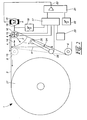
- the belt 2 is formed in this embodiment of a wire of a dewatering device 3 a papermaking machine.
- the dewatering device 3 has a rotatable drum 4, which is wrapped by a wet paper web 5. On the outside, the tape 2 is pressed against the paper web 5, so that the paper web 5 is held between the wire 2 and the drum 4.
- the band 2 is under a predetermined tensile stress in order to achieve the desired dewatering effect for the paper web 5. In this case, the excess water contained in the paper web 5 is pressed through this due to the pressure of the wire 2.
- To achieve a sufficient dewatering effect several dewatering devices 3 are arranged one behind the other.
- the band 2 is deflected by four rollers 6, 7, 8, 9.
- the rollers 6, 9 are fixed in their axial position and therefore serve as pure guide rollers 6, 9th
- the roller 7 is pivotally mounted in the direction of arrow 10 and forms a stripline roller.
- the band 2 can be influenced in its direction. This is important to keep the tape 2 in place.
- an edge sensor 11 is provided, which detects the position of the tape 2 and a tape guide controller 12 feeds. This tape drive compares the output from the edge sensor 11 signal with a setpoint and controls accordingly, not shown actuator of the belt roller 7. In this way, a tape running control is achieved.
- the tension control roller 8 by an actuator 13 in the direction of arrow 14 is adjustable. The farther the tensioning roller 8 is moved to the right of the representation indicated by dashed lines, the higher is the tensile force introduced into the belt 2.
- the tension control roller 8 is formed simultaneously as a force measuring roller 15.
- the force measuring roller 15 is equipped on both bearings with force sensors 16 which measure the bearing force. These force sensors 16 determine the bearing force of the force measuring roller 15 in two mutually perpendicular directions, so that in addition to the amount of the bearing force and their direction can be determined.
- the force sensors 16 are in operative connection with a correction device 17, which calculates the tape tensile force from the measured vectorial bearing force F.
- the amount of the determined bearing force F and ⁇ is the angle between the measured force direction and the tape running direction between the rollers 7 and 8.
- the adjustment of the tensioning roller 8 is selected parallel to the strip running direction between the rollers 7 and 8, so that a simple geometric condition for the calculation of the belt tensile force F results.
- the correction device 17 is in operative connection with a displacement sensor 18, which detects the respective position of the actuator 13.
- the displacement sensor 18 is in operative connection with a drive shaft 19 of the actuator 13.
- the correction device 17 receives a signal representing the position of the tension control roller 8.
- the correction device 17 is associated with a storage device 20 in which the positions of the rollers 7 and 9 are stored.
- H is the height difference between the rollers 8 and 9 in the vertical projection on the belt plane between the rollers 7 and 8 and x the respective position of the tensioning roller 8, based on the position of the guide roller 9.
- the belt tension can be determined directly from the measured bearing force F, the position of the rollers 7, 9 and the respective position x of the tension control roller 8.
- a sensor 24 is provided which detects the run of the rotating belt tapering to the force measuring roller 15.
- the running of the force measuring roller 15 run of the circulating belt 2 could be detected by another sensor 24, but this is not necessary in the embodiment, since the position of this strand is independent of the position of the tension control roller 8.
- the sensor 24 has a pivotally supported freely rotatable roller 25, which is resiliently pressed against the rotating belt 2.
- the sensor 24 also has a potentiometer 26 which detects the pivotal position of the roller 25 and converts it into an electrical signal. This electrical signal is proportional to the wrapping of the force measuring roller 15 and the correction device 17 is supplied.
- the correction device 17 is operatively connected to a control device 21, which receives the belt tension determined by the correction device 17 as an actual value and compares it with a desired value of a setpoint value generator 22.
- the control device 21 preferably has a PID behavior and acts with its output 23 on the actuator 13 a.
- the desired band tension can be adjusted by adjusting the output from the setpoint generator 22 setpoint, which is then adjusted by the control device 21 by adjusting the tension control roller 8.
- FIG. 2 shows a schematic representation of a second embodiment of the device 1 according to Figure 1, wherein like reference numerals designate like parts. In the following, only the differences from the embodiment according to FIG. 1 will be explained.
- the device 1 according to FIG. 2 serves to detect and regulate the tension of a moving web 2, which is deflected by rollers 6, 15 and wound onto a winder 27. In reverse web direction of the winder 27 could also be used as Abwickler.
- the roller 15 is designed as a force measuring roller whose bearing forces are detected vectorially by means of the force sensor 16.
- the force measuring roller 15 is adjustable in the direction of arrow 14 by means of the actuator 13 to the desired Adjust tension of the web 2.
- the wrap angle ⁇ of the force measuring roller 15 is determined on the one hand by the position of the force measuring roller 15 and on the other hand by the diameter of the winder 27. This diameter changes depending on the progress of the winding or unwinding process. Due to the vectorial detection of the bearing force of the force measuring roller 15, the web tension can nevertheless be determined with sufficient accuracy.
Landscapes
- Paper (AREA)
- Controlling Rewinding, Feeding, Winding, Or Abnormalities Of Webs (AREA)
- Drives For Endless Conveyors (AREA)
Priority Applications (1)
| Application Number | Priority Date | Filing Date | Title |
|---|---|---|---|
| PL04012854T PL1484443T3 (pl) | 2003-06-06 | 2004-06-01 | Urządzenie i sposób regulacji siły naprężającej wstęgi w ruchu |
Applications Claiming Priority (2)
| Application Number | Priority Date | Filing Date | Title |
|---|---|---|---|
| DE10326133A DE10326133B4 (de) | 2003-06-06 | 2003-06-06 | Vorrichtung und Verfahren zum Regeln der Spannkraft eines umlaufenden Bandes |
| DE10326133 | 2003-06-06 |
Publications (2)
| Publication Number | Publication Date |
|---|---|
| EP1484443A1 EP1484443A1 (de) | 2004-12-08 |
| EP1484443B1 true EP1484443B1 (de) | 2007-08-22 |
Family
ID=29594662
Family Applications (1)
| Application Number | Title | Priority Date | Filing Date |
|---|---|---|---|
| EP04012854A Expired - Lifetime EP1484443B1 (de) | 2003-06-06 | 2004-06-01 | Vorrichtung und Verfahren zum Regeln der Spannkraft einer laufenden Bahn |
Country Status (7)
Families Citing this family (14)
| Publication number | Priority date | Publication date | Assignee | Title |
|---|---|---|---|---|
| DE10326133B4 (de) * | 2003-06-06 | 2009-04-30 | Erhardt + Leimer Gmbh | Vorrichtung und Verfahren zum Regeln der Spannkraft eines umlaufenden Bandes |
| FI114929B (fi) | 2003-08-27 | 2005-01-31 | Metso Paper Inc | Menetelmä ja laitteisto kudoskiristimen toiminnan kartoittamiseksi paperikoneessa |
| DE102005044339B4 (de) * | 2005-09-16 | 2016-01-14 | Siemens Aktiengesellschaft | Verfahren zum Betrieb einer Wicklermaschine |
| DE102006024032A1 (de) * | 2006-05-23 | 2007-11-29 | Voith Patent Gmbh | Anordnung zur Bandregelung |
| US7370542B2 (en) * | 2006-07-10 | 2008-05-13 | Cnh America Llc | Flat belt durability tester |
| GB2478725A (en) * | 2010-03-16 | 2011-09-21 | Markem Imaje Ltd | Tape printer having movable guide member to adjust ribbon tension |
| IT1399946B1 (it) * | 2010-04-29 | 2013-05-09 | Clevertech Srl | Dispositivo di avvolgimento di un nastro. |
| WO2012135866A2 (en) * | 2011-04-01 | 2012-10-04 | Heber Gerald J | Improved conveyor belt take-up assembly and method |
| US9334932B2 (en) * | 2011-05-13 | 2016-05-10 | Litens Automotive Partnership | Intelligent belt drive system and method |
| US10029876B2 (en) * | 2012-04-27 | 2018-07-24 | Web Industries, Inc. | Interliner method and apparatus |
| DE102015008219A1 (de) | 2015-06-29 | 2016-12-29 | Texmag Gmbh Vertriebsgesellschaft | Vorrichtung zum Spannen eines umlaufenden Endlosbandes |
| DE102019112868A1 (de) * | 2019-01-23 | 2020-07-23 | Homag Gmbh | Transportsystem sowie Transportverfahren |
| DE102019004034A1 (de) * | 2019-06-07 | 2020-12-10 | Texmag Gmbh Vertriebsgesellschaft | Verfahren zum Erfassen einer Zugspannung eines umlaufenden Bandes |
| CN110594372B (zh) * | 2019-09-18 | 2022-11-22 | 西安应用光学研究所 | 一种适用于有限空间的自适应有限转角预紧传动装置 |
Family Cites Families (13)
| Publication number | Priority date | Publication date | Assignee | Title |
|---|---|---|---|---|
| JPS57161344A (en) * | 1981-03-27 | 1982-10-04 | Nippon Denso Co Ltd | Belt tension control device |
| IT1191352B (it) * | 1986-03-14 | 1988-03-16 | Emm Srl | Dispositivo per la tesatura del tessuto in formazione in una macchina automatica rettilinea per maglieria |
| IT1251039B (it) * | 1991-08-01 | 1995-05-02 | Pirelli Transmissioni Ind Spa | Metodo e dispositivo per controllare lo stato di usura del tessuto di rivestimento di una cinghia di trasmissione |
| FR2681617B1 (fr) * | 1991-09-24 | 1993-12-24 | Lajtos Automation | Enrouleur-derouleur de materiau plan, notamment textile, a double-sens et a tension controlee. |
| DE4439889C1 (de) * | 1994-11-08 | 1996-08-14 | Erhardt & Leimer Gmbh | Verfahren und Vorrichtung zur Bandzugregelung und zum Führen eines umlaufenden Endlosbandes |
| DE19503457C1 (de) * | 1995-02-03 | 1996-07-04 | Daimler Benz Ag | Verfahren zur Überwachung des Verschleißes zumindest einer Motorsteuerkette und eine Diagnoseeinrichtung zur Durchführung desselben |
| DE19511110A1 (de) * | 1995-03-25 | 1996-09-26 | Haehne Elektronische Messgerae | Vorrichtung zur Bandzugmessung |
| JPH08326853A (ja) * | 1995-05-30 | 1996-12-10 | Honda Motor Co Ltd | 内燃機関における無端伝動帯の張力調整装置 |
| JP2000238945A (ja) * | 1999-02-18 | 2000-09-05 | Toshiba Corp | 抄紙機の張力制御装置 |
| JP4503778B2 (ja) * | 2000-03-29 | 2010-07-14 | 本田技研工業株式会社 | 除雪機 |
| US6834228B2 (en) * | 2001-10-25 | 2004-12-21 | The Gates Corporation | Belt drive system with automatic belt tension control |
| US6849011B2 (en) * | 2002-11-23 | 2005-02-01 | International Truck Intellectual Property Company, Llc | Engine endless drive belt tensioner and tensioner position indicator |
| DE10326133B4 (de) * | 2003-06-06 | 2009-04-30 | Erhardt + Leimer Gmbh | Vorrichtung und Verfahren zum Regeln der Spannkraft eines umlaufenden Bandes |
-
2003
- 2003-06-06 DE DE10326133A patent/DE10326133B4/de not_active Expired - Lifetime
- 2003-07-31 DE DE20311822U patent/DE20311822U1/de not_active Expired - Lifetime
-
2004
- 2004-06-01 AT AT04012854T patent/ATE371053T1/de active
- 2004-06-01 EP EP04012854A patent/EP1484443B1/de not_active Expired - Lifetime
- 2004-06-01 PL PL04012854T patent/PL1484443T3/pl unknown
- 2004-06-01 DE DE502004004697T patent/DE502004004697D1/de not_active Expired - Lifetime
- 2004-06-01 ES ES04012854T patent/ES2291773T3/es not_active Expired - Lifetime
- 2004-06-03 JP JP2004166262A patent/JP4868487B2/ja not_active Expired - Lifetime
- 2004-06-05 US US10/861,838 patent/US7059984B2/en not_active Expired - Lifetime
Also Published As
| Publication number | Publication date |
|---|---|
| JP4868487B2 (ja) | 2012-02-01 |
| JP2004360166A (ja) | 2004-12-24 |
| DE10326133B4 (de) | 2009-04-30 |
| ES2291773T3 (es) | 2008-03-01 |
| EP1484443A1 (de) | 2004-12-08 |
| DE20311822U1 (de) | 2003-11-20 |
| DE502004004697D1 (de) | 2007-10-04 |
| US20040245363A1 (en) | 2004-12-09 |
| ATE371053T1 (de) | 2007-09-15 |
| US7059984B2 (en) | 2006-06-13 |
| PL1484443T3 (pl) | 2008-01-31 |
| DE10326133A1 (de) | 2005-01-13 |
Similar Documents
| Publication | Publication Date | Title |
|---|---|---|
| EP1484443B1 (de) | Vorrichtung und Verfahren zum Regeln der Spannkraft einer laufenden Bahn | |
| EP2392529B1 (de) | Regelung der Bahnspannung einer Warenbahn | |
| EP2371748B1 (de) | Verfahren zur Bestimmung wenigstens eines Reglerparameters eines Tänzerlage-Regelglieds | |
| DE69614433T2 (de) | Verfahren und Vorrichtung zum Berechnen und Regeln der Dehnung einer laufenden Materialbahn | |
| DE69912100T2 (de) | Verfahren und vorrichtung zum wickeln einer bahn | |
| EP0433718A1 (de) | Verfahren und Vorrichtung zum Wickeln von Folienbahnen | |
| WO2003011728A1 (de) | Verfahren zur steuerung eines rollenspeichers und rollenspeicher zum speichern blattförmiger gegenstände | |
| DE2432368B2 (de) | Verfahren zum Aufwickeln eines Bandes auf eine Wickelrolle | |
| DE10158985A1 (de) | Dehnungssteuerung im Einzug einer Druckmaschine | |
| DE112006001914T5 (de) | Verfahren zum Aurollen einer Papier- oder Kartonbahn, und Rollapparat | |
| DE4439908A1 (de) | Verfahren und Vorrichtung zum Aufwickeln von bahnförmigem Material | |
| EP1000893B1 (de) | Wickelmaschine zum Aufwickeln einer Materialbahn | |
| CH687995A5 (de) | Verfahren und Vorrichtung zum Schaeren von Faeden. | |
| DE4131760C2 (de) | Verfahren und Vorrichtung zum Regeln der Bahnzugkraft einer Textilbahn | |
| DE69915602T2 (de) | Verfahren und vorrichtung zur wickelkontrolle | |
| DE2857504C2 (de) | Vorrichtung zur Regelung der Dicke von thermoplastischen Folien | |
| AT517296B1 (de) | Spulmaschine zum Aufwickeln von Spulgut | |
| EP0417232B1 (de) | Bahnlaufregler | |
| DE3527178A1 (de) | Verfahren und vorrichtung zum aufwickeln einer materialbahn | |
| DE3713915A1 (de) | Elektrische zugkraft-regelvorrichtung fuer wickelvorgaenge | |
| DE10036306B4 (de) | Verfahren und Vorrichtung zum gleichzeitigen Wickeln von mehreren Teilbahnen zu Teilbahnrollen | |
| DE10141549C1 (de) | Verfahren zur Zugkraftmessung an laufenden Materialien sowie Vorrichtung zur Ausübung des Verfahrens | |
| CH662547A5 (en) | Device for winding and unwinding an imbricated stream of flat articles, such as paper sheets | |
| EP1577241B1 (de) | Markierungseinheit für eine Materialbahn | |
| EP1514816B1 (de) | Wickelmaschine zum Wickeln einer Materialbahn |
Legal Events
| Date | Code | Title | Description |
|---|---|---|---|
| PUAI | Public reference made under article 153(3) epc to a published international application that has entered the european phase |
Free format text: ORIGINAL CODE: 0009012 |
|
| AK | Designated contracting states |
Kind code of ref document: A1 Designated state(s): AT BE BG CH CY CZ DE DK EE ES FI FR GB GR HU IE IT LI LU MC NL PL PT RO SE SI SK TR |
|
| AX | Request for extension of the european patent |
Extension state: AL HR LT LV MK |
|
| 17P | Request for examination filed |
Effective date: 20050223 |
|
| AKX | Designation fees paid |
Designated state(s): AT BE BG CH CY CZ DE DK EE ES FI FR GB GR HU IE IT LI LU MC NL PL PT RO SE SI SK TR |
|
| 17Q | First examination report despatched |
Effective date: 20070125 |
|
| GRAP | Despatch of communication of intention to grant a patent |
Free format text: ORIGINAL CODE: EPIDOSNIGR1 |
|
| GRAS | Grant fee paid |
Free format text: ORIGINAL CODE: EPIDOSNIGR3 |
|
| GRAA | (expected) grant |
Free format text: ORIGINAL CODE: 0009210 |
|
| AK | Designated contracting states |
Kind code of ref document: B1 Designated state(s): AT BE BG CH CY CZ DE DK EE ES FI FR GB GR HU IE IT LI LU MC NL PL PT RO SE SI SK TR |
|
| REG | Reference to a national code |
Ref country code: GB Ref legal event code: FG4D Free format text: NOT ENGLISH |
|
| REG | Reference to a national code |
Ref country code: CH Ref legal event code: EP |
|
| REG | Reference to a national code |
Ref country code: IE Ref legal event code: FG4D Free format text: LANGUAGE OF EP DOCUMENT: GERMAN |
|
| REF | Corresponds to: |
Ref document number: 502004004697 Country of ref document: DE Date of ref document: 20071004 Kind code of ref document: P |
|
| REG | Reference to a national code |
Ref country code: CH Ref legal event code: NV Representative=s name: TROESCH SCHEIDEGGER WERNER AG |
|
| REG | Reference to a national code |
Ref country code: SE Ref legal event code: TRGR |
|
| GBT | Gb: translation of ep patent filed (gb section 77(6)(a)/1977) |
Effective date: 20071128 |
|
| PG25 | Lapsed in a contracting state [announced via postgrant information from national office to epo] |
Ref country code: NL Free format text: LAPSE BECAUSE OF FAILURE TO SUBMIT A TRANSLATION OF THE DESCRIPTION OR TO PAY THE FEE WITHIN THE PRESCRIBED TIME-LIMIT Effective date: 20070822 Ref country code: BG Free format text: LAPSE BECAUSE OF FAILURE TO SUBMIT A TRANSLATION OF THE DESCRIPTION OR TO PAY THE FEE WITHIN THE PRESCRIBED TIME-LIMIT Effective date: 20071122 |
|
| REG | Reference to a national code |
Ref country code: PL Ref legal event code: T3 |
|
| NLV1 | Nl: lapsed or annulled due to failure to fulfill the requirements of art. 29p and 29m of the patents act | ||
| REG | Reference to a national code |
Ref country code: ES Ref legal event code: FG2A Ref document number: 2291773 Country of ref document: ES Kind code of ref document: T3 |
|
| ET | Fr: translation filed | ||
| REG | Reference to a national code |
Ref country code: IE Ref legal event code: FD4D |
|
| PG25 | Lapsed in a contracting state [announced via postgrant information from national office to epo] |
Ref country code: GR Free format text: LAPSE BECAUSE OF FAILURE TO SUBMIT A TRANSLATION OF THE DESCRIPTION OR TO PAY THE FEE WITHIN THE PRESCRIBED TIME-LIMIT Effective date: 20071123 Ref country code: DK Free format text: LAPSE BECAUSE OF FAILURE TO SUBMIT A TRANSLATION OF THE DESCRIPTION OR TO PAY THE FEE WITHIN THE PRESCRIBED TIME-LIMIT Effective date: 20070822 |
|
| PG25 | Lapsed in a contracting state [announced via postgrant information from national office to epo] |
Ref country code: PT Free format text: LAPSE BECAUSE OF FAILURE TO SUBMIT A TRANSLATION OF THE DESCRIPTION OR TO PAY THE FEE WITHIN THE PRESCRIBED TIME-LIMIT Effective date: 20080122 Ref country code: IE Free format text: LAPSE BECAUSE OF FAILURE TO SUBMIT A TRANSLATION OF THE DESCRIPTION OR TO PAY THE FEE WITHIN THE PRESCRIBED TIME-LIMIT Effective date: 20070822 |
|
| PLBE | No opposition filed within time limit |
Free format text: ORIGINAL CODE: 0009261 |
|
| STAA | Information on the status of an ep patent application or granted ep patent |
Free format text: STATUS: NO OPPOSITION FILED WITHIN TIME LIMIT |
|
| PG25 | Lapsed in a contracting state [announced via postgrant information from national office to epo] |
Ref country code: RO Free format text: LAPSE BECAUSE OF FAILURE TO SUBMIT A TRANSLATION OF THE DESCRIPTION OR TO PAY THE FEE WITHIN THE PRESCRIBED TIME-LIMIT Effective date: 20070822 |
|
| 26N | No opposition filed |
Effective date: 20080526 |
|
| PGFP | Annual fee paid to national office [announced via postgrant information from national office to epo] |
Ref country code: SK Payment date: 20080627 Year of fee payment: 5 |
|
| PGFP | Annual fee paid to national office [announced via postgrant information from national office to epo] |
Ref country code: SE Payment date: 20080609 Year of fee payment: 5 |
|
| BERE | Be: lapsed |
Owner name: ERHARDT + LEIMER G.M.B.H. Effective date: 20080630 |
|
| PG25 | Lapsed in a contracting state [announced via postgrant information from national office to epo] |
Ref country code: MC Free format text: LAPSE BECAUSE OF NON-PAYMENT OF DUE FEES Effective date: 20080630 |
|
| PG25 | Lapsed in a contracting state [announced via postgrant information from national office to epo] |
Ref country code: BE Free format text: LAPSE BECAUSE OF NON-PAYMENT OF DUE FEES Effective date: 20080630 |
|
| PG25 | Lapsed in a contracting state [announced via postgrant information from national office to epo] |
Ref country code: EE Free format text: LAPSE BECAUSE OF FAILURE TO SUBMIT A TRANSLATION OF THE DESCRIPTION OR TO PAY THE FEE WITHIN THE PRESCRIBED TIME-LIMIT Effective date: 20070822 |
|
| PG25 | Lapsed in a contracting state [announced via postgrant information from national office to epo] |
Ref country code: SI Free format text: LAPSE BECAUSE OF FAILURE TO SUBMIT A TRANSLATION OF THE DESCRIPTION OR TO PAY THE FEE WITHIN THE PRESCRIBED TIME-LIMIT Effective date: 20070822 |
|
| PG25 | Lapsed in a contracting state [announced via postgrant information from national office to epo] |
Ref country code: CY Free format text: LAPSE BECAUSE OF FAILURE TO SUBMIT A TRANSLATION OF THE DESCRIPTION OR TO PAY THE FEE WITHIN THE PRESCRIBED TIME-LIMIT Effective date: 20070822 |
|
| REG | Reference to a national code |
Ref country code: SK Ref legal event code: MM4A Ref document number: E 2634 Country of ref document: SK Effective date: 20090601 |
|
| PG25 | Lapsed in a contracting state [announced via postgrant information from national office to epo] |
Ref country code: SK Free format text: LAPSE BECAUSE OF NON-PAYMENT OF DUE FEES Effective date: 20090601 |
|
| PG25 | Lapsed in a contracting state [announced via postgrant information from national office to epo] |
Ref country code: HU Free format text: LAPSE BECAUSE OF FAILURE TO SUBMIT A TRANSLATION OF THE DESCRIPTION OR TO PAY THE FEE WITHIN THE PRESCRIBED TIME-LIMIT Effective date: 20080223 Ref country code: LU Free format text: LAPSE BECAUSE OF NON-PAYMENT OF DUE FEES Effective date: 20080601 |
|
| PG25 | Lapsed in a contracting state [announced via postgrant information from national office to epo] |
Ref country code: TR Free format text: LAPSE BECAUSE OF FAILURE TO SUBMIT A TRANSLATION OF THE DESCRIPTION OR TO PAY THE FEE WITHIN THE PRESCRIBED TIME-LIMIT Effective date: 20070822 |
|
| PG25 | Lapsed in a contracting state [announced via postgrant information from national office to epo] |
Ref country code: SE Free format text: LAPSE BECAUSE OF NON-PAYMENT OF DUE FEES Effective date: 20090602 |
|
| REG | Reference to a national code |
Ref country code: FR Ref legal event code: PLFP Year of fee payment: 13 |
|
| REG | Reference to a national code |
Ref country code: FR Ref legal event code: PLFP Year of fee payment: 14 |
|
| PGFP | Annual fee paid to national office [announced via postgrant information from national office to epo] |
Ref country code: GB Payment date: 20170626 Year of fee payment: 14 Ref country code: CZ Payment date: 20170531 Year of fee payment: 14 Ref country code: CH Payment date: 20170606 Year of fee payment: 14 |
|
| PGFP | Annual fee paid to national office [announced via postgrant information from national office to epo] |
Ref country code: AT Payment date: 20170629 Year of fee payment: 14 Ref country code: PL Payment date: 20170516 Year of fee payment: 14 |
|
| PGFP | Annual fee paid to national office [announced via postgrant information from national office to epo] |
Ref country code: ES Payment date: 20170703 Year of fee payment: 14 |
|
| REG | Reference to a national code |
Ref country code: FR Ref legal event code: PLFP Year of fee payment: 15 |
|
| PG25 | Lapsed in a contracting state [announced via postgrant information from national office to epo] |
Ref country code: CZ Free format text: LAPSE BECAUSE OF NON-PAYMENT OF DUE FEES Effective date: 20180601 |
|
| REG | Reference to a national code |
Ref country code: CH Ref legal event code: PL |
|
| REG | Reference to a national code |
Ref country code: AT Ref legal event code: MM01 Ref document number: 371053 Country of ref document: AT Kind code of ref document: T Effective date: 20180601 |
|
| GBPC | Gb: european patent ceased through non-payment of renewal fee |
Effective date: 20180601 |
|
| PG25 | Lapsed in a contracting state [announced via postgrant information from national office to epo] |
Ref country code: LI Free format text: LAPSE BECAUSE OF NON-PAYMENT OF DUE FEES Effective date: 20180630 Ref country code: CH Free format text: LAPSE BECAUSE OF NON-PAYMENT OF DUE FEES Effective date: 20180630 Ref country code: GB Free format text: LAPSE BECAUSE OF NON-PAYMENT OF DUE FEES Effective date: 20180601 Ref country code: AT Free format text: LAPSE BECAUSE OF NON-PAYMENT OF DUE FEES Effective date: 20180601 |
|
| REG | Reference to a national code |
Ref country code: ES Ref legal event code: FD2A Effective date: 20190913 |
|
| PG25 | Lapsed in a contracting state [announced via postgrant information from national office to epo] |
Ref country code: ES Free format text: LAPSE BECAUSE OF NON-PAYMENT OF DUE FEES Effective date: 20180602 |
|
| PG25 | Lapsed in a contracting state [announced via postgrant information from national office to epo] |
Ref country code: PL Free format text: LAPSE BECAUSE OF NON-PAYMENT OF DUE FEES Effective date: 20180601 |
|
| PGFP | Annual fee paid to national office [announced via postgrant information from national office to epo] |
Ref country code: FR Payment date: 20230623 Year of fee payment: 20 Ref country code: DE Payment date: 20230621 Year of fee payment: 20 |
|
| PGFP | Annual fee paid to national office [announced via postgrant information from national office to epo] |
Ref country code: FI Payment date: 20230620 Year of fee payment: 20 |
|
| PGFP | Annual fee paid to national office [announced via postgrant information from national office to epo] |
Ref country code: IT Payment date: 20230629 Year of fee payment: 20 |
|
| REG | Reference to a national code |
Ref country code: DE Ref legal event code: R071 Ref document number: 502004004697 Country of ref document: DE |