EP1483090B1 - Allesschneider mit einem einschubgeh use - Google Patents
Allesschneider mit einem einschubgeh use Download PDFInfo
- Publication number
- EP1483090B1 EP1483090B1 EP03717191A EP03717191A EP1483090B1 EP 1483090 B1 EP1483090 B1 EP 1483090B1 EP 03717191 A EP03717191 A EP 03717191A EP 03717191 A EP03717191 A EP 03717191A EP 1483090 B1 EP1483090 B1 EP 1483090B1
- Authority
- EP
- European Patent Office
- Prior art keywords
- housing
- wall
- carrier
- support
- universal slicer
- Prior art date
- Legal status (The legal status is an assumption and is not a legal conclusion. Google has not performed a legal analysis and makes no representation as to the accuracy of the status listed.)
- Expired - Lifetime
Links
- 230000005540 biological transmission Effects 0.000 claims description 8
- 229920003023 plastic Polymers 0.000 claims description 6
- 239000004033 plastic Substances 0.000 claims description 6
- 239000000463 material Substances 0.000 claims description 5
- 238000005520 cutting process Methods 0.000 abstract description 3
- 238000002347 injection Methods 0.000 description 4
- 239000007924 injection Substances 0.000 description 4
- 238000001746 injection moulding Methods 0.000 description 3
- 238000003780 insertion Methods 0.000 description 3
- 230000037431 insertion Effects 0.000 description 3
- 229910052782 aluminium Inorganic materials 0.000 description 2
- XAGFODPZIPBFFR-UHFFFAOYSA-N aluminium Chemical compound [Al] XAGFODPZIPBFFR-UHFFFAOYSA-N 0.000 description 2
- 238000010276 construction Methods 0.000 description 2
- 238000004512 die casting Methods 0.000 description 2
- 238000009434 installation Methods 0.000 description 2
- 238000004519 manufacturing process Methods 0.000 description 2
- 238000003860 storage Methods 0.000 description 2
- 241000237858 Gastropoda Species 0.000 description 1
- 239000000969 carrier Substances 0.000 description 1
- 229910052751 metal Inorganic materials 0.000 description 1
- 239000002184 metal Substances 0.000 description 1
- 238000000034 method Methods 0.000 description 1
- 238000000465 moulding Methods 0.000 description 1
- 238000005507 spraying Methods 0.000 description 1
Images


Classifications
-
- B—PERFORMING OPERATIONS; TRANSPORTING
- B26—HAND CUTTING TOOLS; CUTTING; SEVERING
- B26D—CUTTING; DETAILS COMMON TO MACHINES FOR PERFORATING, PUNCHING, CUTTING-OUT, STAMPING-OUT OR SEVERING
- B26D7/00—Details of apparatus for cutting, cutting-out, stamping-out, punching, perforating, or severing by means other than cutting
-
- B—PERFORMING OPERATIONS; TRANSPORTING
- B26—HAND CUTTING TOOLS; CUTTING; SEVERING
- B26D—CUTTING; DETAILS COMMON TO MACHINES FOR PERFORATING, PUNCHING, CUTTING-OUT, STAMPING-OUT OR SEVERING
- B26D1/00—Cutting through work characterised by the nature or movement of the cutting member or particular materials not otherwise provided for; Apparatus or machines therefor; Cutting members therefor
- B26D1/01—Cutting through work characterised by the nature or movement of the cutting member or particular materials not otherwise provided for; Apparatus or machines therefor; Cutting members therefor involving a cutting member which does not travel with the work
- B26D1/12—Cutting through work characterised by the nature or movement of the cutting member or particular materials not otherwise provided for; Apparatus or machines therefor; Cutting members therefor involving a cutting member which does not travel with the work having a cutting member moving about an axis
- B26D1/14—Cutting through work characterised by the nature or movement of the cutting member or particular materials not otherwise provided for; Apparatus or machines therefor; Cutting members therefor involving a cutting member which does not travel with the work having a cutting member moving about an axis with a circular cutting member, e.g. disc cutter
- B26D1/143—Cutting through work characterised by the nature or movement of the cutting member or particular materials not otherwise provided for; Apparatus or machines therefor; Cutting members therefor involving a cutting member which does not travel with the work having a cutting member moving about an axis with a circular cutting member, e.g. disc cutter rotating about a stationary axis
-
- Y—GENERAL TAGGING OF NEW TECHNOLOGICAL DEVELOPMENTS; GENERAL TAGGING OF CROSS-SECTIONAL TECHNOLOGIES SPANNING OVER SEVERAL SECTIONS OF THE IPC; TECHNICAL SUBJECTS COVERED BY FORMER USPC CROSS-REFERENCE ART COLLECTIONS [XRACs] AND DIGESTS
- Y10—TECHNICAL SUBJECTS COVERED BY FORMER USPC
- Y10T—TECHNICAL SUBJECTS COVERED BY FORMER US CLASSIFICATION
- Y10T83/00—Cutting
- Y10T83/222—With receptacle or support for cut product
-
- Y—GENERAL TAGGING OF NEW TECHNOLOGICAL DEVELOPMENTS; GENERAL TAGGING OF CROSS-SECTIONAL TECHNOLOGIES SPANNING OVER SEVERAL SECTIONS OF THE IPC; TECHNICAL SUBJECTS COVERED BY FORMER USPC CROSS-REFERENCE ART COLLECTIONS [XRACs] AND DIGESTS
- Y10—TECHNICAL SUBJECTS COVERED BY FORMER USPC
- Y10T—TECHNICAL SUBJECTS COVERED BY FORMER US CLASSIFICATION
- Y10T83/00—Cutting
- Y10T83/647—With means to convey work relative to tool station
- Y10T83/6492—Plural passes of diminishing work piece through tool station
- Y10T83/6499—Work rectilinearly reciprocated through tool station
-
- Y—GENERAL TAGGING OF NEW TECHNOLOGICAL DEVELOPMENTS; GENERAL TAGGING OF CROSS-SECTIONAL TECHNOLOGIES SPANNING OVER SEVERAL SECTIONS OF THE IPC; TECHNICAL SUBJECTS COVERED BY FORMER USPC CROSS-REFERENCE ART COLLECTIONS [XRACs] AND DIGESTS
- Y10—TECHNICAL SUBJECTS COVERED BY FORMER USPC
- Y10T—TECHNICAL SUBJECTS COVERED BY FORMER US CLASSIFICATION
- Y10T83/00—Cutting
- Y10T83/768—Rotatable disc tool pair or tool and carrier
- Y10T83/7734—With guard for tool
-
- Y—GENERAL TAGGING OF NEW TECHNOLOGICAL DEVELOPMENTS; GENERAL TAGGING OF CROSS-SECTIONAL TECHNOLOGIES SPANNING OVER SEVERAL SECTIONS OF THE IPC; TECHNICAL SUBJECTS COVERED BY FORMER USPC CROSS-REFERENCE ART COLLECTIONS [XRACs] AND DIGESTS
- Y10—TECHNICAL SUBJECTS COVERED BY FORMER USPC
- Y10T—TECHNICAL SUBJECTS COVERED BY FORMER US CLASSIFICATION
- Y10T83/00—Cutting
- Y10T83/869—Means to drive or to guide tool
- Y10T83/8759—With means to connect or disconnect tool and its drive
Definitions
- the invention relates to a Alllesschneider according to the preamble of claim 1.
- a generic food slicer is from the DE 26 01 269 known.
- This known household cutting machine comprises a one-piece housing of a lower part and a shell.
- the upper part is frame-shaped and is closed by a cover plate.
- a circular disc-shaped recess is incorporated, in which a disk-shaped circular blade is housed, which is mounted in the upper part and driven in rotation by an arranged behind the upper part of the electric motor.
- the EP 0 115 788 A1 discloses an all-time snail, in which one of the upper or lower narrow-side housing walls shown as separate from the housing can be removed.
- the object of the invention is to make the case of a slicer in a simple manner with high rigidity. Furthermore, it is an object of the invention to provide a food slicer, in which the assembly is facilitated.
- This object is achieved with a slicer with the features of claim 1.
- one of the narrow-side housing walls is designed removable and the other housing walls are connected to form a unit, a simple housing structure results with high rigidity.
- the other housing walls are connected to a unit, resulting in a very rigid structure of the housing.
- This connected unit forms a basic housing, in which the necessary components such as drive motor and gear can be used on a narrow side of the at least approximately cuboid housing.
- the approximately cuboid housing, which forms a connected unit has on one of its narrow sides an opening which can be closed by a removable housing wall.
- the housing thus forms a stable unit whose interior is accessible via a narrow-side opening.
- the removable housing wall is formed by the end wall of the housing.
- different models of slicer can have a similar basic housing, can be used in the model-specific end walls.
- the same basic housing can be used with different models.
- Model differences resulting for example by design or controls, can be realized in different end walls, which are used in a similar basic housing.
- a large number of model variants can be realized without significantly increasing the number of parts.
- the housing in addition to the removable narrow-side housing wall serving to form the housing further housing walls are integrally connected to each other.
- the front housing wall, the rear wall and three narrow-side housing walls thereby form an integral unit.
- This one-piece assembly can be made in metal die-cutters in the die-cast aluminum process. In plastic slicers, the one-piece assembly can be made by injection molding. By the one-piece molding or spraying of the base housing additional fastening means and assembly steps for connecting the housing walls can be omitted.
- the basic housing designed in this way can thus be manufactured inexpensively.
- the production by die casting or by injection molding also makes it possible to form ribs inside the housing, which additionally stiffen the housing. By forming stiffening ribs, a high stability of the basic housing is achieved even with smaller wall thicknesses. If the housing can be manufactured with smaller wall thicknesses, the result is advantageously a material saving.
- a carrier is inserted into the housing, which receives the transmission and the drive motor.
- the assembly of the food slicer can be simplified in a particularly advantageous manner, if a carrier is provided, on which at least the drive motor and the transmission are pre-assembled.
- the carrier may be formed, for example, frame-shaped or base plate-shaped. At this chassis-like structure of the carrier, the gear and the drive motor can be pre-assembled. Additional components of the food slicer can in suitably be pre-assembled in addition to the carrier.
- the preassembled carrier can then be inserted in a simple assembly step on a narrow-side opening of the base housing and fixed in the housing. For this purpose, the carrier may be supported on at least one inner side of the housing.
- a guide is provided on the inside of the housing and the carrier is inserted by means of this guide into the housing.
- the guide thereby facilitates the insertion of the carrier and at the same time supports the carrier within the housing in its installed position.
- the insertion and support of the carrier inside the housing is similar to the insertion and supporting a drawer in a cabinet.
- the housing has latching means and the carrier is fixed in the latching means.
- the carrier When the carrier is inserted into the housing, engage the locking means provided and the carrier is thereby secured in the housing. It is therefore unnecessary to attach the carrier with separate fasteners on the housing.
- the locking means are formed as depressions on the inside of the housing, which engage in retaining lugs, which are fastened by means of resilient latching hooks on the carrier.
- the housing In order to produce the housing in a simple manner, for example in one piece by injection molding or die casting, it is advantageous to form the recesses on the inside of the housing. This has the advantage that the one-piece housing is easily demolded after production.
- the carrier Since the carrier is preferably constructed in the shape of a frame, it is possible in a simple manner to fasten the resilient latching hooks which have the retaining lugs to the carrier.
- the resilient latching hooks with the retaining lugs can advantageously be formed directly on the support.
- the latching means are arranged in the vicinity of the bearing for the rotary blade or in the vicinity of the bearing for a drive pinion.
- the locking means which can be formed preferably of resilient latching hook, so can either be arranged on the removable housing wall, or be arranged on the bearing for the circular blade, or be arranged on the bearing for the drive pinion.
- the carrier can be connected to a bearing plate which carries the gear and the drive motor.
- a bearing plate creates a particularly rigid connection between the first bearing for the circular blade and the second bearing for the drive pinion.
- the further advantage of such a bearing plate is that the carrier can be made of a material of lesser strength per se. This has the advantage that the carrier can be inexpensively made from a low-cost material. Since the bearing plate transmits the essential forces from the first bearing for the circular blade on the second bearing for the drive pinion, it is sufficient to form this bearing plate of a higher quality, high strength material.
- the carrier may be meaningfully connected to the face plate.
- it is cost-effective to form the carrier together with the end plate as a one-piece component.
- stiffening ribs which are arranged extending between the carrier and end plate.
- the one-piece component may be formed of carrier and face plate as a plastic injection molded part or as an aluminum die-cast part.
- the push-button switch for switching on and off the drive motor and a possibly provided locking mechanism for the push-button switch are integrated in the face plate.
- Different models can be produced solely by different end plates.
- the different end plates can have different shapes.
- the different models may also differ by differently designed push-button or by a different number of push-buttons.
- Various models can also be realized in that the carrier may have different gear and / or drive motors.
- the end plates for different models can be designed differently and also the required components such as the transmission and the drive motor may be different depending on the model.
- the different models can be preformed at the respective carriers.
- the preassembled carrier with the respective end plate can then be inserted into a generally used basic housing and secured therein.
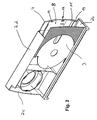
- the food slicer in Figure 1 shows a cuboid housing 2.
- the housing 2 is formed as a one-piece plastic injection molded part and comprises a rear wall 4, a bottom surface 2b, a top surface 2d and a rear, narrow-side housing wall 2c.
- the housing 2 further comprises a front wall 3, which is hidden in the view in Figure 1 and therefore not visible.
- the cuboidal housing 2 is closed at its front by a removable housing wall 2a, a narrow side wall of the housing 2 forms.
- the removable housing wall 2a has the end wall 10 of the food slicer.
- a key switch 22 is arranged on a top surface of the end wall 10.
- the end wall 10 carries a locking mechanism 23rd
- the cuboid housing 2 is shown.
- the cuboid housing 2 is formed as a one-piece plastic injection molded part.
- the housing 2 has a front wall 3 and a rear wall 4, which is arranged at a distance from the front wall 3. Between front wall 3 and rear wall 4, a gap 5 is formed. This space 5 is accessible via an opening 8.
- a carrier 9, as shown for example in Figure 3 in the space 5 of the cuboid housing 2 can be inserted.
- guides 11 are formed, on which the carrier 9 of Figure 3 in the housing 2 can be inserted.
- the guides 11 are formed as integrally molded strips on the inner walls of the front wall 3 and the rear wall 4.
- a circular blade not shown, can be used.
- FIG. 3 shows a carrier 9 according to the invention.
- the carrier 9 is designed as a one-piece plastic injection molded part and comprises the removable housing wall 2a or the end wall C.
- resilient latching hooks 16 are formed which have retaining lugs 15.
- the retaining lugs 15 engage in associated latching means 12 on the inner sides of the housing 2 a.
- the locking means 12 are formed as depressions on the inside of the front wall 3 and the rear wall 4, as seen in Figure 2.
- the carrier 9 is formed together with the end wall 10 as a one-piece component.
- the carrier 9 comprises a bearing plate 20 which carries a gear 6 and a drive motor 7.
- the transmission 6 comprises a bearing 18, in which a drive pinion 19 is inserted.
- a further storage 17 for a circular blade 5 is arranged.
- the first bearing 17 is held by means of a second one-piece component 21 at a distance from the second bearing 18. All components comprising the drive motor 7, the transmission 6, the first bearing 17 and the second bearing 18 are pre-assembled on the carrier 9.
- a push-button switch 22 is integrated into the removable housing wall 2a.
- the end wall 10 has a locking mechanism 23 which blocks the key switch 22 in the engaged position.
- the completely pre-assembled unit as shown in Figure 3, is in the integrally formed, cuboid housing 2, as in Figure 2 is shown, can be inserted.
- the completely pre-assembled carrier 9 according to FIG. 3 can be inserted into the integrally formed cuboid housing 2.
- the inserted into the housing 2 carrier 9 then forms the complete food slicer of Figure 1.
Landscapes
- Life Sciences & Earth Sciences (AREA)
- Forests & Forestry (AREA)
- Engineering & Computer Science (AREA)
- Mechanical Engineering (AREA)
- Food-Manufacturing Devices (AREA)
- Crushing And Pulverization Processes (AREA)
- Control And Other Processes For Unpacking Of Materials (AREA)
- Knives (AREA)
Description
- Die Erfindung betrifft einen Alllesschneider nach dem Oberbegriff des Patentanspruch 1.
- Ein gattungsgemäßer Allesschneider ist aus der
DE 26 01 269 bekannt. Diese bekannte Haushaltsschneidemaschine umfasst ein einstückiges Gehäuse aus einem Unterteil und einem Oberteil. Das Oberteil ist rahmenförmig ausgebildet und ist durch eine Abdeckplatte abgeschlossen. In der Abdeckplatte ist eine kreisscheibenförmige Vertiefung eingearbeitet, in der ein scheibenförmiges Rundmesser untergebracht ist, das in dem Oberteil gelagert und von einem hinter dem Oberteil angeordneter Elektromotor rotierend angetrieben ist. DieEP 0 115 788 A1 offenbart einen Allesschneicher, bei dem eine der als getrennt von dem Gehäuse dargestellten, oberen oder unteren Schmalseitigen Gehäusewände entnehmbar ist. - Nachteilig an diesen bekannten Haushaltsschneidemaschinen ist, dass das Gehäuse sehr kompliziert aufgebaut ist und die Montage sehr aufwendig ist.
- Aufgabe der Erfindung ist es, das Gehäuse eines Allesschneiders in einfacher Weise mit hoher Steifigkeit zu gestalten. Weiterhin ist es Aufgabe der Erfindung, einen Allesschneider zu schaffen, bei dem die Montage erleichtert ist.
- Diese Aufgabe wird mit einem Allesschneider mit den Merkmalen des Anspruchs 1 gelöst. Indem eine der schmalseitigen Gehäusewände entnehmbar ausgebildet ist und die weiteren Gehäusewände zu einer Einheit verbunden sind, ergibt sich ein einfacher Gehäuseaufbau mit hoher Steifigkeit. Indem die weiteren Gehäusewände zu einer Einheit verbunden sind, ergibt sich ein sehr steifer Aufbau des Gehäuses. Diese verbundene Einheit bildet ein Grundgehäuse, in das die nötigen Bauteile wie zum Beispiel Antriebsmotor und Getriebe über eine Schmalseite des zumindest annähernd quaderförmigen Gehäuses eingesetzt werden können. Das annähernd quaderförmige Gehäuse, welches eine verbundene Einheit bildet, weist an einer seiner Schmalseiten eine Öffnung auf, die durch eine entnehmbare Gehäusewand verschließbar ist. Das Gehäuse bildet somit eine stabile Einheit, deren Innenraum über eine schmalseitige Öffnung zugänglich ist. Dies hat den Vorteil, dass das zu einer Einheit verbundene Gehäuse bereits eine sehr hohe Steifigkeit aufweist und die entnehmbare Gehäusewand daran in einfacher Weise befestigt werden kann.
- Die entnehmbare Gehäusewand ist durch die Stirnwand des Gehäuses gebildet. Indem die Stirnwand entnehmbar ist, können unterschiedliche Modelle von Allesschneider ein gleichartiges Grundgehäuse aufweisen, in das modellspezifische Stirnwände eingesetzt werden können. So kann bei verschiedenen Modellen das gleiche Grundgehäuse verwendet werden. Modellunterschiede, die sich beispielsweise durch Design oder Bedienelemente ergeben, können in verschiedenen Stirnwänden verwirklicht werden, die in ein gleichartiges Grundgehäuse eingesetzt werden. So kann eine hohe Anzahl an Modellvarianten realisiert werden, ohne dass sich die Teilevielfalt wesentlich erhöht.
- In einer Ausgestaltung sind die neben der entnehmbaren schmalseitigen Gehäusewand zur Bildung des Gehäuse dienenden weiteren Gehäusewände einstückig miteinander verbunden. Die vordere Gehäusewand, die Rückwand und drei schmalseitige Gehäusewände bilden dabei eine einstückige Baueinheit. Diese einstückige Baueinheit kann bei Metallallesschneidern im Aluminiumdruckgussverfahren hergestellt sein. Bei Kunststoff-Allesschneidern kann die einstückige Baueinheit im Spritzgussverfahren hergestellt sein. Durch das einstückige Gießen bzw. Spritzen des Grundgehäuses können zusätzliche Befestigungsmittel und Montageschritte zum Verbinden der Gehäusewände wegfallen. Das derart gestaltete Grundgehäuse kann somit kostengünstig gefertigt werden. Die Herstellung im Druckgussverfahren bzw. im Spritzgussverfahren ermöglicht es auch, im Inneren des Gehäuses Rippen anzuformen, die das Gehäuse zusätzlich versteifen. Durch das Anformen von Versteifungsrippen wird eine hohe Stabilität des Grundgehäuses auch bei geringeren Wandstärken erreicht. Kann das Gehäuse mit geringeren Wandstärken gefertigt werden, so ergibt sich vorteilhaft eine Materialeinsparung.
- In einer bevorzugten Ausgestaltung der Erfindung ist in das Gehäuse ein Träger einschiebbar, der das Getriebe und den Antriebsmotor aufnimmt. Die Montage des Allesschneiders kann in besonders vorteilhafter Weise vereinfacht werden, wenn ein Träger vorgesehen ist, an dem zumindest der Antriebsmotor und das Getriebe vormontiert sind. Der Träger kann beispielsweise rahmenförmig oder grundplattenförmig ausgebildet sein. An diesem chassisartigen Aufbau des Trägers kann das Getriebe und der Antriebsmotor vormontiert werden. Zusätzliche Bauteile des Allesschneiders können in geeigneter Weise zusätzlich an dem Träger vormontiert sein. Der vormontierte Träger kann dann in einem einfachen Montageschritt über die eine schmalseitige Öffnung des Grundgehäuses eingeschoben und im Gehäuse fixiert werden. Dazu kann der Träger an mindestens einer Innenseite des Gehäuses abgestützt sein. Vorzugsweise ist an der Innenseite des Gehäuse eine Führung vorgesehen und der Träger ist mittels dieser Führung in das Gehäuse einschiebbar. Die Führung erleichtert dadurch das Einschieben des Trägers und stützt gleichzeitig den Träger innerhalb des Gehäuses in seiner Einbaulage. Das Einschieben und Abstützen des Trägers im Inneren des Gehäuses erfolgt ähnlich dem Einschieben und Abstützen einer Schublade in einen Schrank. Durch die Führung des Trägers an der Innenseite des Gehäuses wird die Einbaulage des Trägers eindeutig festgelegt. Durch die eindeutige Festlegung der Einbaulage für den Träger können Montagefehler vermieden werden.
- Besonders vorteilhaft ist es, wenn das Gehäuse Rastmittel aufweist und der Träger in den Rastmitteln fixiert ist. Wenn der Träger in das Gehäuse eingeschoben ist, verrasten die vorgesehenen Rastmittel und der Träger ist dadurch im Gehäuse befestigt. Es erübrigt somit, den Träger mit gesonderten Befestigungsmitteln am Gehäuse zu befestigen. Durch das Einschieben des Trägers werden also alle Bauteile des Allesschneiders in das Gehäuse eingefügt und durch das Einrasten des Rastmittels wird der Träger am Gehäuse befestigt. Durch diese Bauweise ergibt sich eine besonders einfache Montage.
- Vorzugsweise sind die Rastmittel als Vertiefungen an der Innenseite des Gehäuses ausgebildet, die in Haltenasen eingreifen, die mittels federnder Rasthaken an dem Träger befestigt sind. Um das Gehäuse in einfacher Weise, zum Beispiel einteilig im Spritzgussverfahren oder im Druckgussverfahren herstellen zu können, ist es günstig, die Vertiefungen an der Innenseite des Gehäuses auszubilden. Dies hat den Vorteil, dass das einstückige Gehäuse nach der Fertigung leicht entformbar ist. Da der Träger vorzugsweise rahmenförmig aufgebaut ist, ist es in einfacher Weise möglich, die federnden Rasthaken, welche die Haltenasen aufweisen, an dem Träger zu befestigen. Die federnden Rasthaken mit den Haltenasen können in vorteilhafter Weise direkt an dem Träger angeformt sein.
- Günstig ist es, wenn die Rastmittel in der Nähe der Lagerung für das Rundmesser oder in der Nähe der Lagerung für ein Antriebsritzel angeordnet sind. Die Rastmittel, welche vorzugsweise aus federnden Rasthaken gebildet werden, können also entweder an der entnehmbaren Gehäusewand angeordnet sein, oder an der Lagerung für das Rundmesser angeordnet sein, oder an der Lagerung für das Antriebsritzel angeordnet sein. Je nach Anforderung an die Steifigkeit des Aufbaus können diese verschiedenen Anordnungen von Rastmitteln miteinander kombiniert werden. Besonders sinnvoll ist es, Rastmittel im Bereich der Lagerung für das Rundmesser und im Bereich der Lagerung für das Antriebsritzel vorzusehen. Da die größten Beanspruchungen im Bereich dieser beiden Lager auftreten, ist es besonders günstig, dort die Rastmittel vorzusehen.
- Um die Steifigkeit des gesamten Antriebsstranges ausgehend von Motor über Getriebe hin zum Rundmesser zu erhöhen, kann insbesondere der Träger mit einer Lagerplatte verbunden sein, die das Getriebe und den Antriebsmotor trägt. Eine solche Lagerplatte schafft eine besonders steife Verbindung zwischen der ersten Lagerung für das Rundmesser und der zweiten Lagerung für das Antriebsritzel. Der weitere Vorteil einer solchen Lagerplatte ist es, dass der Träger an sich aus einem Material geringerer Festigkeit ausgebildet sein kann. Dies hat den Vorteil, dass der Träger kostengünstig aus einem preisgünstigen Material hergestellt werden kann. Da die Lagerplatte die wesentlichen Kräfte von der ersten Lagerung für das Rundmesser auf die zweite Lagerung für das Antriebsritzel überträgt, genügt es, diese Lagerplatte aus einem höherwertigeren, hochfesten Material auszubilden.
- Der Träger kann sinnvoller Weise mit der Stirnplatte verbunden sein. Insbesondere ist es kostengünstig, den Träger zusammen mit der Stirnplatte als einstückiges Bauteil auszubilden. Es können Versteifungsrippen vorgesehen sein, die zwischen Träger und Stirnplatte verlaufend angeordnet sind. Insbesondere kann das einstückige Bauteil aus Träger und Stirnplatte als Kunststoffspritzgussteil oder als Aluminiumdruckgussteil ausgebildet sein.
- In einer weiteren bevorzugten Ausgestaltung der Erfindung sind insbesondere der Tastschalter zum Ein- und Ausschalten des Antriebsmotors und ein eventuell vorgesehener Verriegelungsmechanismus für den Tastschalter in der Stirnplatte integriert. Dies hat den Vorteil, dass auch die Bedienelemente in die Stirnplatte integriert sind. Dadurch ergibt sich der besondere Vorteil, dass sich verschiedene Modelle eines Allesschneiders nur im Aufbau und Aussehen der Stirnplatte unterscheiden können.
- Unterschiedliche Modelle können allein durch unterschiedliche Stirnplatten erzeugt werden. Die unterschiedlichen Stirnplatten können dabei unterschiedliche Gestalt aufweisen. Die unterschiedlichen Modelle können sich auch durch unterschiedlich gestaltete Tastschalter oder durch eine unterschiedliche Anzahl von Tastschaltern unterscheiden. Verschiedene Modelle können auch dadurch realisiert werden, dass der Träger unterschiedliche Getriebe und/oder Antriebsmotoren aufweisen kann. So können die Stirnplatten für verschiedene Modelle unterschiedlich gestaltet sein und auch die benötigten Bauteile wie zum Beispiel das Getriebe und der Antriebsmotor können je nach Modell unterschiedlich sein. Die unterschiedlichen Modelle können dabei an den jeweiligen Trägern vorformiert sein. Der vormontierte Träger mit der jeweiligen Stirnplatte kann dann in ein generell verwendetes Grundgehäuse eingeschoben und darin befestigt sein.
- Eine bevorzugte Ausführungsform des erfindungsgemäßen Allesschneiders ist in den Zeichnungen dargestellt.
- Es zeigen:
- Figur 1
- einen erfindungsgemäßen Allesschneider in einer perspektivischen Ansicht,
- Figur 2
- eine perspektivische Ansicht des Gehäuses eines erfindungsgemäßen Allesschneiders,
- Figur 3
- eine perspektivische Ansicht eines Trägers mit einer Stirnplatte und einer Lagerplatte, die ein Getriebe und einen Antriebsmotor trägt.
- Der Allesschneider in Figur 1 zeigt ein quaderförmiges Gehäuse 2. Das Gehäuse 2 ist als einstückiges Kunststoffspritzgussteil ausgebildet und umfasst eine Rückwand 4, eine Bodenfläche 2b, eine Deckfläche 2d und eine hintere, schmalseitige Gehäusewand 2c. Das Gehäuse 2 umfaßt weiterhin eine vordere Wand 3, welche in der Ansicht in Figur 1 verdeckt und daher nicht zu sehen ist. Das quaderförmige Gehäuse 2 wird an seiner Vorderseite durch eine entnehmbare Gehäusewand 2a abgeschlossen, die eine schmalseitige Wand des Gehäuses 2 bildet. Die entnehmbare Gehäusewand 2a weist die Stirnwand 10 des Allesschneiders auf. In der Stirnwand 10 ist ein Tastschalter 22 auf einer Deckfläche der Stirnwand 10 angeordnet. Des weiteren trägt die Stirnwand 10 einen Verriegelungsmechanismus 23.
- In Figur 2 ist das quaderförmige Gehäuse 2 gezeigt. Das quaderförmige Gehäuse 2 ist als einteiliges Kunststoffspritzgussteil ausgebildet. Das Gehäuse 2 weist eine vordere Wand 3 auf und eine Rückwand 4, die im einen Abstand zur vorderen Wand 3 angeordnet ist. Zwischen vorderer Wand 3 und Rückwand 4 wird ein Zwischenraum 5 gebildet. Dieser Zwischenraum 5 ist über eine Öffnung 8 zugänglich. In die Öffnung 8 ist ein Träger 9, wie er beispielsweise in Figur 3 dargestellt ist, in den Zwischenraum 5 des quaderförmigen Gehäuse 2 einschiebbar. An den Innenseiten des Gehäuses 2 sind Führungen 11 angeformt, an denen der Träger 9 aus Figur 3 in das Gehäuse 2 einschiebbar ist. Die Führungen 11 sind als angeformte Leisten an den Innenwänden der vorderen Wand 3 und der Rückwand 4 ausgebildet. An der Vorderseite der vorderen Wand 3 ist ein nicht dargestelltes Rundmesser einsetzbar.
- Die Figur 3 zeigt einen erfindungsgemäßen Träger 9. Der Träger 9 ist als einstückiges Kunststoffspritzgussteil ausgebildet und umfasst die entnehmbare Gehäusewand 2a bzw. die Stirnwand C. An dem Träger 9 sind federnde Rasthaken 16 angeformt, die Haltenasen 15 aufweisen. Die Haltenasen 15 greifen in zugeordnete Rastmittel 12 an den Innenseiten des Gehäuses 2 ein. Die Rastmittel 12 sind als Vertiefungen an der Innenseite der vorderen Wand 3 und der Rückwand 4 ausgebildet, wie in Figur 2 zu sehen. Der Träger 9 ist zusammen mit der Stirnwand 10 als einstückiges Bauteil ausgebildet. Der Träger 9 umfaßt eine Lagerplatte 20, die ein Getriebe 6 und einen Antriebsmotor 7 trägt. Das Getriebe 6 umfaßt eine Lagerung 18, in der ein Antriebsritzel 19 eingesetzt ist. In einem Abstand zur Lagerung 18 ist eine weitere Lagerung 17 für ein Rundmesser 5 angeordnet. Die erste Lagerung 17 ist mittels eines zweiten einstückigen Bauteils 21 im Abstand zum zweiten Lager 18 gehalten. Alle Komponenten, umfassend den Antriebsmotor 7, das Getriebe 6, die erste Lagerung 17 und die zweite Lagerung 18 sind an dem Träger 9 vormontiert. Des weiteren ist ein Tastschalter 22 In die entnehmbare Gehäusewand 2a integriert. Die Stirnwand 10 weist einen Verriegelungsmechanismus 23 auf, der in der eingerückten Lage den Tastschalter 22 blockiert. Die komplett vormontierte Baueinheit, wie sie in Figur 3 dargestellt ist, ist in das einstückig ausgebildete, quaderförmige Gehäuse 2, wie es in Figur 2 dargestellt ist, einschiebbar. Der komplett vormontierte Träger 9 gemäß Figur 3 ist in das einstückig ausgebildete quaderförmige Gehäuse 2 einschiebbar. Der in das Gehäuse 2 eingeschobene Träger 9 bildet dann den komplettierten Allesschneider gemäß Figur 1.
Claims (9)
- Allesschneider mit einem zumindest annähernd quaderförmigen Gehäuse (2), das eine Rückwand (4) und eine vordere Wand (3) aufweist, die zur Rückwand (4) beabstandet angeordnet ist, wodurch ein Zwischenraum (5) gebildet ist, der über eine entnehmbare Gehäusewand (2a) zugänglich ist und der zur Aufnahme einer einen Antriebsmotor (7) und ein Getriebe (6) aufweisenden Antriebseinheit dient, die zum Antrieb eines Rundmessers (1) vorgesehen ist, das der vorderen Wand (3) zugeordnet ist, wobei die entnehmbare Gehäusewand (2a) durch eine schmalseitige Stirnwand (10) des Gehäuses gebildet ist und wobei die weiteren Gehäusewände (2b,2c,2d) einstückig miteinander zu einer Einheit verbunden sind und in das Gehäuse (2) ein Träger (9), der mit der Stirnwand (10) als einstückiges Bauteil ausgebildet ist und das Getriebe (6) und den Antriebsmotor (7) aufnimmt, einschiebbar ist, dadurch gekennzeichnet, daß das einstückige Bauteil Versteifungsrippen aufweist, die zwischen Träger (9) und Stirnwand (10) verlaufend angeordnet sind.
- Allesschneider nach Anspruch 1, dadurch gekennzeichnet, dass der Träger (9) an mindestens einer Innenseite des Gehäuses (2) abgestützt ist.
- Allesschneider nach Anspruch 2, dadurch gekennzeichnet, dass an der Innenseite des Gehäuses (2) eine Führung (11) vorgesehen ist und der Träger (9) mittels der Führung (11) in das Gehäuse (2) einschiebbar ist.
- Allesschneider nach Anspruch 2 oder 3, dadurch gekennzeichnet, dass das Gehäuse (2) Rastmittel (12) aufweist und der Träger (9) in den Rastmitteln (12) fixiert ist.
- Allesschneider nach Anspruch 4, dadurch gekennzeichnet, dass die Rastmittel (12) als Vertiefungen (14) an der Innenseite des Gehäuses (2) ausgebildet sind, in die Haltenasen (15) eingreifen, die mittels federnder Rasthaken (16) an dem Träger (9) befestigt sind.
- Allesschneider nach Anspruch 4 oder 5, dadurch gekennzeichnet, dass die Rastmittel (12) in der Nähe einer ersten Lagerung (17) für das Rundmesser (5) angeordnet sind.
- Allesschneider nach einem der Ansprüche 4 bis 6, dadurch gekennzeichnet, dass die Rastmittel (12) in der Nähe einer zweiten Lagerung (18) für ein Antriebsritzel (19) angeordnet sind.
- Allesschneider nach Anspruch 1, dadurch gekennzeichnet, dass der Träger (9) mit einer Lagerplatte (20) verbunden ist, die das Getriebe (6) und den Antriebsmotor (7) trägt.
- Allesschneider nach Anspruch 1, dadurch gekennzeichnet, dass das einstückige Bauteil als Kunststoff-Spritzgussteil hergestellt ist.
Applications Claiming Priority (3)
| Application Number | Priority Date | Filing Date | Title |
|---|---|---|---|
| DE10208489 | 2002-02-27 | ||
| DE2002108489 DE10208489A1 (de) | 2002-02-27 | 2002-02-27 | Allesschneider mit einem Einschubgehäuse |
| PCT/EP2003/001754 WO2003072319A1 (de) | 2002-02-27 | 2003-02-20 | Allesschneider mit einem einschubgehäuse |
Publications (2)
| Publication Number | Publication Date |
|---|---|
| EP1483090A1 EP1483090A1 (de) | 2004-12-08 |
| EP1483090B1 true EP1483090B1 (de) | 2007-09-05 |
Family
ID=27675063
Family Applications (1)
| Application Number | Title | Priority Date | Filing Date |
|---|---|---|---|
| EP03717191A Expired - Lifetime EP1483090B1 (de) | 2002-02-27 | 2003-02-20 | Allesschneider mit einem einschubgeh use |
Country Status (11)
| Country | Link |
|---|---|
| US (1) | US20050051006A1 (de) |
| EP (1) | EP1483090B1 (de) |
| AT (1) | ATE372193T1 (de) |
| AU (1) | AU2003221485A1 (de) |
| DE (2) | DE10208489A1 (de) |
| HR (1) | HRP20040771B1 (de) |
| PL (1) | PL206887B1 (de) |
| RU (1) | RU2313443C2 (de) |
| SI (1) | SI1483090T1 (de) |
| WO (1) | WO2003072319A1 (de) |
| YU (1) | YU72304A (de) |
Families Citing this family (10)
| Publication number | Priority date | Publication date | Assignee | Title |
|---|---|---|---|---|
| DE10358674A1 (de) * | 2003-12-12 | 2005-07-07 | Leader Time Srl | Schneidvorrichtung |
| US20070044612A1 (en) * | 2005-08-26 | 2007-03-01 | Somal Hardev S | Gage plate adjustment mechanism for a food slicer |
| US20070044611A1 (en) * | 2005-08-26 | 2007-03-01 | Bondarowicz Frank A | Food slicer |
| DE102009030227A1 (de) * | 2009-06-23 | 2011-01-05 | Gebr. Graef Gmbh & Co Kg | Schneidemaschine für Lebensmittel |
| DE102010052787A1 (de) * | 2010-11-27 | 2012-05-31 | Bizerba Gmbh & Co Kg | Professionelle Scheibenschneidmaschine mit kompaktem Motor-Getriebe-Einschub |
| DE102011115429A1 (de) * | 2011-10-08 | 2013-04-11 | Bizerba Gmbh & Co. Kg | Verfahren zur Herstellung einer Lebensmittelschneidemaschine |
| USD690564S1 (en) | 2011-10-10 | 2013-10-01 | Calphalon Corporation | Mandolin |
| JP6411303B2 (ja) * | 2015-09-08 | 2018-10-24 | 株式会社ベンリナー | スライサー |
| RU186996U1 (ru) * | 2018-10-04 | 2019-02-12 | Ньургун Павлович Макаров | Ломтерезка для крупноразмерных пищевых продуктов |
| US11491563B2 (en) | 2020-10-13 | 2022-11-08 | Trent N. Butcher | Cutting systems and related methods |
Family Cites Families (10)
| Publication number | Priority date | Publication date | Assignee | Title |
|---|---|---|---|---|
| DE1778553A1 (de) * | 1968-05-10 | 1971-12-16 | Ritterwerk F Ritter & Sohn | Elektrisch angetriebene Brot-und Aufschnittschneidemaschine |
| DE6906246U (de) * | 1969-02-18 | 1970-04-16 | Metallindustrie Denkingen Gebr | Schneidmaschine |
| DE2629352C2 (de) * | 1976-06-30 | 1985-02-07 | Bosch-Siemens Hausgeräte GmbH, 7000 Stuttgart | Schneidmaschine für Lebensmittel, insbesondere Haushalts-Schneidemaschine |
| JPS5524857A (en) * | 1978-08-08 | 1980-02-22 | Aichi Electric Mfg | Motor food slice machine |
| US4273013A (en) * | 1979-07-09 | 1981-06-16 | Sunbeam Corporation | Slicing machine |
| US4345498A (en) * | 1980-06-18 | 1982-08-24 | Rival Manufacturing Company | Food slicing machine |
| US4520703A (en) * | 1982-05-18 | 1985-06-04 | Bosch-Siemens Hausgeraete Gmbh | Electromotively driven household slicing machine for food |
| DE3304611A1 (de) * | 1983-02-10 | 1984-08-16 | Bizerba-Werke Wilhelm Kraut GmbH & Co KG, 7460 Balingen | Vorrichtung zur kuehlung des elektrischen antriebsmotors fuer das kreismesser einer aufschnitt-schneidemaschine |
| US5026335A (en) * | 1989-03-03 | 1991-06-25 | Deere & Company | Downshifting work vehicle using differential lock switch |
| EP0386393A1 (de) * | 1989-03-10 | 1990-09-12 | Angela Tognoli | Aufschnittsschneidemaschine |
-
2002
- 2002-02-27 DE DE2002108489 patent/DE10208489A1/de not_active Withdrawn
-
2003
- 2003-02-20 PL PL369974A patent/PL206887B1/pl unknown
- 2003-02-20 SI SI200331037T patent/SI1483090T1/sl unknown
- 2003-02-20 WO PCT/EP2003/001754 patent/WO2003072319A1/de active IP Right Grant
- 2003-02-20 RU RU2004124524A patent/RU2313443C2/ru not_active IP Right Cessation
- 2003-02-20 EP EP03717191A patent/EP1483090B1/de not_active Expired - Lifetime
- 2003-02-20 AT AT03717191T patent/ATE372193T1/de active
- 2003-02-20 YU YUP72304 patent/YU72304A/sh unknown
- 2003-02-20 AU AU2003221485A patent/AU2003221485A1/en not_active Abandoned
- 2003-02-20 DE DE50308116T patent/DE50308116D1/de not_active Expired - Lifetime
-
2004
- 2004-08-26 HR HRP20040771AA patent/HRP20040771B1/xx not_active IP Right Cessation
- 2004-08-27 US US10/928,222 patent/US20050051006A1/en not_active Abandoned
Also Published As
| Publication number | Publication date |
|---|---|
| DE10208489A1 (de) | 2003-09-04 |
| SI1483090T1 (sl) | 2008-02-29 |
| HRP20040771A2 (en) | 2005-02-28 |
| WO2003072319A1 (de) | 2003-09-04 |
| RU2004124524A (ru) | 2005-06-10 |
| YU72304A (sh) | 2006-03-03 |
| US20050051006A1 (en) | 2005-03-10 |
| ATE372193T1 (de) | 2007-09-15 |
| PL369974A1 (en) | 2005-05-02 |
| RU2313443C2 (ru) | 2007-12-27 |
| PL206887B1 (pl) | 2010-10-29 |
| EP1483090A1 (de) | 2004-12-08 |
| HRP20040771B1 (en) | 2012-06-30 |
| DE50308116D1 (de) | 2007-10-18 |
| AU2003221485A1 (en) | 2003-09-09 |
Similar Documents
| Publication | Publication Date | Title |
|---|---|---|
| EP1728034B1 (de) | Verfahren zur befestigung von elementen an der innenverkleidung von kühl- und/oder gefriergeräten und verfahren zur herstellung einer solchen befestigungsanordnung | |
| EP1483090B1 (de) | Allesschneider mit einem einschubgeh use | |
| WO1990009299A1 (de) | Wischeranlage | |
| EP2464926B1 (de) | Abstellfach für ein kältegerät | |
| EP2005092A2 (de) | Kältegerät mit unterteiltem innenraum | |
| WO2001076900A1 (de) | Kunststoffträgerteil angespritzt am fahrzeugtürinnenblech gegen feuchtigkeitseindringung und verfahren zu seiner herstellung | |
| DE3007760A1 (de) | Kotfluegelaufbau | |
| WO1995002916B1 (de) | Antriebsvorrichtung für ein verstellbares fahrzeugteil | |
| EP1895252B1 (de) | Kühl- und/oder Gefriergerät | |
| DE19539972A1 (de) | Antriebsvorrichtung für mindestens zwei Scheibenwischer eines Fahrzeuges | |
| EP1657110A1 (de) | Dachbalken für Einsatzfahrzeuge | |
| EP2464928B1 (de) | Kältegerät | |
| EP3537077B1 (de) | Kühlgutabstellfach mit l-förmigen rahmen, tür sowie haushaltskältegerät | |
| EP1095232B1 (de) | Abstellfach | |
| EP1030144B1 (de) | Wand mit Halteelementen | |
| DE102010002159B4 (de) | Vorrichtung zum Verbinden einer Antriebseinheit für eine Verstelleinrichtung eines Kraftfahrzeugsitzes mit der Festigkeitsstruktur des Kraftfahrzeugsitzes | |
| EP3571366B1 (de) | Kraftfahrzeug-türgriff-system | |
| DE3444143A1 (de) | Zweiteiliges gehaeuse fuer elektromotore | |
| DE29919824U1 (de) | Gehäuse für die Rudermaschine von Fahrzeugmodellen | |
| EP0213296B1 (de) | Anordnung zum Ein- und Ausschalten eines Staubsaugers | |
| DE3743916A1 (de) | Schneidemaschine, insbesondere elektromotorisch angetriebene haushalt-schneidemaschine | |
| DE1103453B (de) | Motorgetriebeblock fuer elektrische Haushaltgeraete geringer Leistung | |
| DE3521014A1 (de) | Halter fuer nummerntafel | |
| DE102021202259A1 (de) | Haushaltskältegerät mit scharnierartiger Befestigung einer wannenförmigen Abdeckung für eine Öffnung einer Innenwandung, sowie Verfahren | |
| EP3760954A1 (de) | Haushaltsgerätevorrichtung |
Legal Events
| Date | Code | Title | Description |
|---|---|---|---|
| PUAI | Public reference made under article 153(3) epc to a published international application that has entered the european phase |
Free format text: ORIGINAL CODE: 0009012 |
|
| 17P | Request for examination filed |
Effective date: 20040927 |
|
| AK | Designated contracting states |
Kind code of ref document: A1 Designated state(s): AT BE BG CH CY CZ DE DK EE ES FI FR GB GR HU IE IT LI LU MC NL PT SE SI SK TR |
|
| AX | Request for extension of the european patent |
Extension state: AL LT LV MK RO |
|
| GRAP | Despatch of communication of intention to grant a patent |
Free format text: ORIGINAL CODE: EPIDOSNIGR1 |
|
| GRAS | Grant fee paid |
Free format text: ORIGINAL CODE: EPIDOSNIGR3 |
|
| GRAA | (expected) grant |
Free format text: ORIGINAL CODE: 0009210 |
|
| AK | Designated contracting states |
Kind code of ref document: B1 Designated state(s): AT BE BG CH CY CZ DE DK EE ES FI FR GB GR HU IE IT LI LU MC NL PT SE SI SK TR |
|
| REG | Reference to a national code |
Ref country code: GB Ref legal event code: FG4D Free format text: NOT ENGLISH |
|
| REG | Reference to a national code |
Ref country code: CH Ref legal event code: EP |
|
| REF | Corresponds to: |
Ref document number: 50308116 Country of ref document: DE Date of ref document: 20071018 Kind code of ref document: P |
|
| REG | Reference to a national code |
Ref country code: IE Ref legal event code: FG4D Free format text: LANGUAGE OF EP DOCUMENT: GERMAN |
|
| ET | Fr: translation filed | ||
| REG | Reference to a national code |
Ref country code: SE Ref legal event code: TRGR |
|
| PG25 | Lapsed in a contracting state [announced via postgrant information from national office to epo] |
Ref country code: ES Free format text: LAPSE BECAUSE OF FAILURE TO SUBMIT A TRANSLATION OF THE DESCRIPTION OR TO PAY THE FEE WITHIN THE PRESCRIBED TIME-LIMIT Effective date: 20071216 Ref country code: FI Free format text: LAPSE BECAUSE OF FAILURE TO SUBMIT A TRANSLATION OF THE DESCRIPTION OR TO PAY THE FEE WITHIN THE PRESCRIBED TIME-LIMIT Effective date: 20070905 |
|
| NLV1 | Nl: lapsed or annulled due to failure to fulfill the requirements of art. 29p and 29m of the patents act | ||
| GBV | Gb: ep patent (uk) treated as always having been void in accordance with gb section 77(7)/1977 [no translation filed] | ||
| REG | Reference to a national code |
Ref country code: IE Ref legal event code: FD4D |
|
| PG25 | Lapsed in a contracting state [announced via postgrant information from national office to epo] |
Ref country code: GR Free format text: LAPSE BECAUSE OF FAILURE TO SUBMIT A TRANSLATION OF THE DESCRIPTION OR TO PAY THE FEE WITHIN THE PRESCRIBED TIME-LIMIT Effective date: 20071206 Ref country code: NL Free format text: LAPSE BECAUSE OF FAILURE TO SUBMIT A TRANSLATION OF THE DESCRIPTION OR TO PAY THE FEE WITHIN THE PRESCRIBED TIME-LIMIT Effective date: 20070905 |
|
| PG25 | Lapsed in a contracting state [announced via postgrant information from national office to epo] |
Ref country code: PT Free format text: LAPSE BECAUSE OF FAILURE TO SUBMIT A TRANSLATION OF THE DESCRIPTION OR TO PAY THE FEE WITHIN THE PRESCRIBED TIME-LIMIT Effective date: 20080206 Ref country code: GB Free format text: LAPSE BECAUSE OF FAILURE TO SUBMIT A TRANSLATION OF THE DESCRIPTION OR TO PAY THE FEE WITHIN THE PRESCRIBED TIME-LIMIT Effective date: 20070905 Ref country code: IE Free format text: LAPSE BECAUSE OF FAILURE TO SUBMIT A TRANSLATION OF THE DESCRIPTION OR TO PAY THE FEE WITHIN THE PRESCRIBED TIME-LIMIT Effective date: 20070905 Ref country code: SK Free format text: LAPSE BECAUSE OF FAILURE TO SUBMIT A TRANSLATION OF THE DESCRIPTION OR TO PAY THE FEE WITHIN THE PRESCRIBED TIME-LIMIT Effective date: 20070905 |
|
| PLBE | No opposition filed within time limit |
Free format text: ORIGINAL CODE: 0009261 |
|
| STAA | Information on the status of an ep patent application or granted ep patent |
Free format text: STATUS: NO OPPOSITION FILED WITHIN TIME LIMIT |
|
| PG25 | Lapsed in a contracting state [announced via postgrant information from national office to epo] |
Ref country code: DK Free format text: LAPSE BECAUSE OF FAILURE TO SUBMIT A TRANSLATION OF THE DESCRIPTION OR TO PAY THE FEE WITHIN THE PRESCRIBED TIME-LIMIT Effective date: 20070905 |
|
| 26N | No opposition filed |
Effective date: 20080606 |
|
| BERE | Be: lapsed |
Owner name: BSH BOSCH UND SIEMENS HAUSGERATE G.M.B.H. Effective date: 20080228 |
|
| REG | Reference to a national code |
Ref country code: CH Ref legal event code: PL |
|
| PG25 | Lapsed in a contracting state [announced via postgrant information from national office to epo] |
Ref country code: CH Free format text: LAPSE BECAUSE OF NON-PAYMENT OF DUE FEES Effective date: 20080229 Ref country code: MC Free format text: LAPSE BECAUSE OF NON-PAYMENT OF DUE FEES Effective date: 20080228 Ref country code: LI Free format text: LAPSE BECAUSE OF NON-PAYMENT OF DUE FEES Effective date: 20080229 |
|
| PG25 | Lapsed in a contracting state [announced via postgrant information from national office to epo] |
Ref country code: EE Free format text: LAPSE BECAUSE OF FAILURE TO SUBMIT A TRANSLATION OF THE DESCRIPTION OR TO PAY THE FEE WITHIN THE PRESCRIBED TIME-LIMIT Effective date: 20070905 |
|
| PG25 | Lapsed in a contracting state [announced via postgrant information from national office to epo] |
Ref country code: BE Free format text: LAPSE BECAUSE OF NON-PAYMENT OF DUE FEES Effective date: 20080228 |
|
| PG25 | Lapsed in a contracting state [announced via postgrant information from national office to epo] |
Ref country code: CY Free format text: LAPSE BECAUSE OF FAILURE TO SUBMIT A TRANSLATION OF THE DESCRIPTION OR TO PAY THE FEE WITHIN THE PRESCRIBED TIME-LIMIT Effective date: 20070905 |
|
| PG25 | Lapsed in a contracting state [announced via postgrant information from national office to epo] |
Ref country code: BG Free format text: LAPSE BECAUSE OF FAILURE TO SUBMIT A TRANSLATION OF THE DESCRIPTION OR TO PAY THE FEE WITHIN THE PRESCRIBED TIME-LIMIT Effective date: 20071205 |
|
| PG25 | Lapsed in a contracting state [announced via postgrant information from national office to epo] |
Ref country code: HU Free format text: LAPSE BECAUSE OF FAILURE TO SUBMIT A TRANSLATION OF THE DESCRIPTION OR TO PAY THE FEE WITHIN THE PRESCRIBED TIME-LIMIT Effective date: 20080306 Ref country code: LU Free format text: LAPSE BECAUSE OF NON-PAYMENT OF DUE FEES Effective date: 20080220 |
|
| PG25 | Lapsed in a contracting state [announced via postgrant information from national office to epo] |
Ref country code: IT Free format text: LAPSE BECAUSE OF NON-PAYMENT OF DUE FEES Effective date: 20080229 |
|
| PGFP | Annual fee paid to national office [announced via postgrant information from national office to epo] |
Ref country code: CZ Payment date: 20110209 Year of fee payment: 9 |
|
| PGFP | Annual fee paid to national office [announced via postgrant information from national office to epo] |
Ref country code: FR Payment date: 20120228 Year of fee payment: 10 |
|
| PGFP | Annual fee paid to national office [announced via postgrant information from national office to epo] |
Ref country code: SE Payment date: 20120221 Year of fee payment: 10 |
|
| REG | Reference to a national code |
Ref country code: SE Ref legal event code: EUG |
|
| PG25 | Lapsed in a contracting state [announced via postgrant information from national office to epo] |
Ref country code: SE Free format text: LAPSE BECAUSE OF NON-PAYMENT OF DUE FEES Effective date: 20130221 Ref country code: CZ Free format text: LAPSE BECAUSE OF NON-PAYMENT OF DUE FEES Effective date: 20130220 |
|
| REG | Reference to a national code |
Ref country code: FR Ref legal event code: ST Effective date: 20131031 |
|
| PG25 | Lapsed in a contracting state [announced via postgrant information from national office to epo] |
Ref country code: FR Free format text: LAPSE BECAUSE OF NON-PAYMENT OF DUE FEES Effective date: 20130228 |
|
| REG | Reference to a national code |
Ref country code: DE Ref legal event code: R081 Ref document number: 50308116 Country of ref document: DE Owner name: BSH HAUSGERAETE GMBH, DE Free format text: FORMER OWNER: BSH BOSCH UND SIEMENS HAUSGERAETE GMBH, 81739 MUENCHEN, DE Effective date: 20150407 |
|
| REG | Reference to a national code |
Ref country code: SI Ref legal event code: SP73 Owner name: BSH HAUSGERAETE GMBH; DE Effective date: 20150529 |
|
| REG | Reference to a national code |
Ref country code: AT Ref legal event code: HC Ref document number: 372193 Country of ref document: AT Kind code of ref document: T Owner name: BSH HAUSGERAETE GMBH, DE Effective date: 20150528 |
|
| PGFP | Annual fee paid to national office [announced via postgrant information from national office to epo] |
Ref country code: DE Payment date: 20180228 Year of fee payment: 16 |
|
| PGFP | Annual fee paid to national office [announced via postgrant information from national office to epo] |
Ref country code: SI Payment date: 20180209 Year of fee payment: 16 Ref country code: AT Payment date: 20180220 Year of fee payment: 16 |
|
| PGFP | Annual fee paid to national office [announced via postgrant information from national office to epo] |
Ref country code: TR Payment date: 20190207 Year of fee payment: 17 |
|
| REG | Reference to a national code |
Ref country code: DE Ref legal event code: R119 Ref document number: 50308116 Country of ref document: DE |
|
| REG | Reference to a national code |
Ref country code: AT Ref legal event code: MM01 Ref document number: 372193 Country of ref document: AT Kind code of ref document: T Effective date: 20190220 |
|
| PG25 | Lapsed in a contracting state [announced via postgrant information from national office to epo] |
Ref country code: SI Free format text: LAPSE BECAUSE OF NON-PAYMENT OF DUE FEES Effective date: 20190221 |
|
| REG | Reference to a national code |
Ref country code: SI Ref legal event code: KO00 Effective date: 20191007 |
|
| PG25 | Lapsed in a contracting state [announced via postgrant information from national office to epo] |
Ref country code: AT Free format text: LAPSE BECAUSE OF NON-PAYMENT OF DUE FEES Effective date: 20190220 |
|
| PG25 | Lapsed in a contracting state [announced via postgrant information from national office to epo] |
Ref country code: DE Free format text: LAPSE BECAUSE OF NON-PAYMENT OF DUE FEES Effective date: 20190903 |
|
| PG25 | Lapsed in a contracting state [announced via postgrant information from national office to epo] |
Ref country code: TR Free format text: LAPSE BECAUSE OF NON-PAYMENT OF DUE FEES Effective date: 20200220 |