EP1482091B1 - Ouvrage avec voie pour système de transport à sustentation magnétique et propulsion par moteur électrique linéaire - Google Patents
Ouvrage avec voie pour système de transport à sustentation magnétique et propulsion par moteur électrique linéaire Download PDFInfo
- Publication number
- EP1482091B1 EP1482091B1 EP04291283A EP04291283A EP1482091B1 EP 1482091 B1 EP1482091 B1 EP 1482091B1 EP 04291283 A EP04291283 A EP 04291283A EP 04291283 A EP04291283 A EP 04291283A EP 1482091 B1 EP1482091 B1 EP 1482091B1
- Authority
- EP
- European Patent Office
- Prior art keywords
- general shape
- tracks
- track
- supports
- forming
- Prior art date
- Legal status (The legal status is an assumption and is not a legal conclusion. Google has not performed a legal analysis and makes no representation as to the accuracy of the status listed.)
- Expired - Lifetime
Links
- 239000000725 suspension Substances 0.000 title 1
- 239000007787 solid Substances 0.000 abstract 1
- 238000005339 levitation Methods 0.000 description 9
- 238000006243 chemical reaction Methods 0.000 description 3
- 238000010276 construction Methods 0.000 description 3
- 102100031497 Heparan sulfate N-sulfotransferase 1 Human genes 0.000 description 2
- 101000588589 Homo sapiens Heparan sulfate N-sulfotransferase 1 Proteins 0.000 description 2
- 230000010354 integration Effects 0.000 description 2
- 238000012423 maintenance Methods 0.000 description 2
- 238000004519 manufacturing process Methods 0.000 description 2
- 230000000694 effects Effects 0.000 description 1
- 238000009434 installation Methods 0.000 description 1
- 238000005457 optimization Methods 0.000 description 1
- 238000000926 separation method Methods 0.000 description 1
Images
Classifications
-
- B—PERFORMING OPERATIONS; TRANSPORTING
- B60—VEHICLES IN GENERAL
- B60L—PROPULSION OF ELECTRICALLY-PROPELLED VEHICLES; SUPPLYING ELECTRIC POWER FOR AUXILIARY EQUIPMENT OF ELECTRICALLY-PROPELLED VEHICLES; ELECTRODYNAMIC BRAKE SYSTEMS FOR VEHICLES IN GENERAL; MAGNETIC SUSPENSION OR LEVITATION FOR VEHICLES; MONITORING OPERATING VARIABLES OF ELECTRICALLY-PROPELLED VEHICLES; ELECTRIC SAFETY DEVICES FOR ELECTRICALLY-PROPELLED VEHICLES
- B60L13/00—Electric propulsion for monorail vehicles, suspension vehicles or rack railways; Magnetic suspension or levitation for vehicles
- B60L13/04—Magnetic suspension or levitation for vehicles
-
- E—FIXED CONSTRUCTIONS
- E01—CONSTRUCTION OF ROADS, RAILWAYS, OR BRIDGES
- E01B—PERMANENT WAY; PERMANENT-WAY TOOLS; MACHINES FOR MAKING RAILWAYS OF ALL KINDS
- E01B25/00—Tracks for special kinds of railways
- E01B25/30—Tracks for magnetic suspension or levitation vehicles
- E01B25/305—Rails or supporting constructions
-
- B—PERFORMING OPERATIONS; TRANSPORTING
- B61—RAILWAYS
- B61B—RAILWAY SYSTEMS; EQUIPMENT THEREFOR NOT OTHERWISE PROVIDED FOR
- B61B13/00—Other railway systems
- B61B13/04—Monorail systems
-
- B—PERFORMING OPERATIONS; TRANSPORTING
- B60—VEHICLES IN GENERAL
- B60L—PROPULSION OF ELECTRICALLY-PROPELLED VEHICLES; SUPPLYING ELECTRIC POWER FOR AUXILIARY EQUIPMENT OF ELECTRICALLY-PROPELLED VEHICLES; ELECTRODYNAMIC BRAKE SYSTEMS FOR VEHICLES IN GENERAL; MAGNETIC SUSPENSION OR LEVITATION FOR VEHICLES; MONITORING OPERATING VARIABLES OF ELECTRICALLY-PROPELLED VEHICLES; ELECTRIC SAFETY DEVICES FOR ELECTRICALLY-PROPELLED VEHICLES
- B60L2200/00—Type of vehicles
- B60L2200/26—Rail vehicles
Definitions
- the invention relates to a structure system with track for a magnetic levitation transport system and propulsion by linear electric motor.
- structures intended to support the circulation of vehicles with magnetic levitation and propulsion by linear electric motor, are made in prefabricated sections assembled on site or cast in place. These structures include crosspieces, each supported by a battery (or pylon), which then receive superstructure one or two ways, placed on sleepers used to adjust and maintain the rails and transmit the efforts to the viaduct.
- the existing viaducts are made to constitute support structures of transport routes, but never, in the road works, and still less in the railway works, the wearing course or the railroad participate in the resistance of the work of art under the effect of permanent and operational charges.
- the track supports the vertical levitation forces, lateral guiding, and longitudinal braking traction and transmits them to the viaduct.
- Wheel-friction monorail support structures generally pneumatic, have a structure that plays both the role of the track and the viaduct.
- the Japanese HSST is conceived without side screens, but its track is conceived in two parts, one consisting of sleepers and rails, which only postpone the efforts on the body of the viaduct, the other of the body the viaduct thus incorporating the element resistant to the forces exerted by the sleepers.
- the object of the invention is to propose the simplification and the optimization of the design, the lightening of the structures, the facilitation of the construction, the reduction of ground support, a system of structure with track for transport system with magnetic levitation and propulsion by linear electric motor
- the lanework structure according to claim 1.
- the structure of art, object of the invention incorporates a succession of longitudinally spaced pylons and supporting said structure in the general form of U or V.
- the object of the invention is remarkable in that the generally T-shaped supports are both part of the track and form an integral part of the structure to ensure the transfer of loads on the piles.
- the invention consists in completely associating the viaduct, the tracks and the track supports, in the context of the envisaged application, in a single work.
- This book has the following characteristics:
- the track supports and the base of the monobloc structure in the general form of U or V is a monobloc structure linearly continuous in the direction of the tracks, so as to be associated with the general strength of the structure.
- the structure thus formed into a single longitudinal structure has the fundamental advantage of postponing efforts on the support pylons of the structure.
- the structure is reduced to a width limited to the dimensions necessary for the support of the reaction and lift rails, at the safety distances to be provided between the tracks to allow the crossing of the vehicles and possibly to the laying of a central bridge, for example a backup and / or maintenance gateway.
- the elements of the structure are cast in place or prefabricated at the factory before being transported to the site to be assembled, according to the profile defined for the transport line to be produced.
- the prefabricated elements are provided on the faces located in interface with the reaction rails of devices for mounting, adjust, fix these rails respecting the profile of the line.
- FIGS 3a to 3c there is shown the relative position of a magnetic levitation train using a structure with monobloc structure according to the subject of the invention.
- the structure with tracks can advantageously be provided with a central bridge P, backup and / or maintenance bridge, respectively, to access the train wagons or evacuate passengers from these, if necessary.
- This central bridge P may, as shown in Figures 3a to 3c, be placed in the center of the monobloc structure in the general form of U or V at least on parts of the structure.
- This gateway can advantageously be an integral part of the structure.
- the rail supports must be placed at the factory in the mold of each prefabricated element.
Landscapes
- Engineering & Computer Science (AREA)
- Mechanical Engineering (AREA)
- Architecture (AREA)
- Civil Engineering (AREA)
- Structural Engineering (AREA)
- Transportation (AREA)
- Electromagnetism (AREA)
- Power Engineering (AREA)
- Physics & Mathematics (AREA)
- Railway Tracks (AREA)
- Control Of Vehicles With Linear Motors And Vehicles That Are Magnetically Levitated (AREA)
- Linear Motors (AREA)
- Non-Mechanical Conveyors (AREA)
- Bridges Or Land Bridges (AREA)
Description
- L'invention concerne un système d'ouvrage avec voie pour système de transport à sustentation magnétique et propulsion par moteur électrique linéaire.
- A l'heure actuelle, les ouvrages d'art (le viaduc) destinés à supporter les circulations de véhicules à sustentation magnétique et à propulsion par moteur électrique linéaire, sont réalisés en tronçons préfabriqués assemblés sur chantier ou coulés en place. Ces ouvrages d'art comportent des traverses, chacune supportée par une pile (ou pylône), qui reçoivent ensuite en superstructure une ou deux voies, posées sur des traverses servant à régler et maintenir les rails et à transmettre les efforts au viaduc.
- Les viaducs existants sont réalisés pour constituer des ouvrages supports de voies de transport, mais jamais, dans les ouvrages routiers, et encore moins dans les ouvrages ferroviaires, la couche de roulement ou la voie ferrée ne participent à la résistance de l'ouvrage d'art sous l'effet des charges permanentes et d'exploitation.
- Les ouvrages de systèmes de transport à sustentation magnétique et propulsion par moteur électrique linéaire existants respectent toujours ce principe de séparation des fonctions et des réactions. La voie supporte les efforts verticaux de sustentation, latéraux de guidage, et longitudinaux de traction freinage et les transmet au viaduc.
- Le brevet HSST déposé aux Etats-Unis : US 5152227, fait état de dispositions de construction qui, ne portant pas sur l'intégration de ce qui semble être la voie dans la constitution de l'ouvrage, ne concerne pas cette particularité, et n'en fait pas mention. Un tel document ne permet pas de déduire l'intégration de la voie dans l'ensemble du viaduc.
- Les ouvrages supports de monorails à traction par friction de roue, en général pneumatiques, ont un ouvrage jouant à la fois le rôle de la voie et du viaduc.
- L'ouvrage HSST réalisé au japon est conçu sans écran latéraux, mais sa voie est conçue en deux parties, l'une constituée des traverses et des rails, qui ne font que reporter les efforts sur le corps du viaduc, l'autre du corps du viaduc intégrant donc l'élément résistant aux efforts exercés par les traverses.
- De JP 60-133101 et de DE 248 941 il est connu un ouvrage d'art pour système de transport à sustentation magnétique associant au moins deux supports de voies en forme générale de T reliés entre eux pour former un ouvrage en forme générale de U.
- L'invention a pour objet de proposer la simplification et l'optimisation de la conception, l'allégement des ouvrages, la facilitation de la construction, la réduction des appuis au sol, un système d'ouvrage avec voie pour système de transport à sustentation magnétique et propulsion par moteur électrique linéaire
- Selon l'invention, l'ouvrage d'art avec voies est conforme à la revendication 1.
- En outre, l'ouvrage d'art, objet de l'invention, intègre une succession de pylônes espacés longitudinalement et supportant ledit ouvrage en forme générale de U ou de V.
- Enfin, l'ouvrage d'art objet de l'invention est remarquable en ce que les supports en forme générale de T sont à la fois constitutifs de la voie et font partie intégrante de la structure pour assurer le report des charges sur les piles.
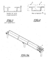
- L'invention sera mieux comprise à la lecture de la description et à l'observation des dessins dans lesquels, outre la figure 1 représentant une vue en coupe d'une structure ou système d'ouvrage de l'art antérieur :
- la figure 2 représente une vue en coupe du système d'ouvrage selon l'invention ;
- la figure 3a représente, à titre illustratif, un train à sustentation magnétique utilisant un ouvrage avec voie conforme à l'objet de la présente invention ;
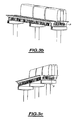
- la figure 3b représente, à titre illustratif, une vue partielle de la figure 3a, montrant la position relative du train à sustentation magnétique et de l'ouvrage d'art ;
- la figure 3c représente une vue plus détaillée de la figure 3b.
- L'invention consiste à associer complètement le viaduc, les voies et les supports de voies, dans le cadre de l'application envisagée, en un seul ouvrage. Cet ouvrage dispose des caractéristiques suivantes :
- Il associe au moins deux supports 4 de voies, chacune en forme générale de T, l'ensemble constituant un seul ouvrage monobloc en forme générale de U ou de V, où les barres verticales des T et celles du U ou du V sont confondues.
- Les supports de voies etla base de l'ouvrage monobloc en forme générale de U ou de V constitue un ouvrage monobloc linéairement continu dans le sens des voies, de manière à être associés à la résistance générale de l'ouvrage.
- L'ouvrage d'art ainsi constitué en une structure longitudinale unique, présente l'avantage fondamental de reporter les efforts sur les pylônes support de l'ouvrage.
- L'ouvrage est réduit à une largeur limitée aux dimensions nécessaires au support des rails de réaction et de sustentation, aux distances de sécurité à prévoir entre les voies pour permettre le croisement des véhicules et éventuellement à la pose d'une passerelle centrale, par exemple une passerelle de secours et/ou de maintenance.
- Les éléments de l'ouvrage sont coulés en place ou préfabriqués en usine avant d'être transportés sur le chantier pour être assemblés, en fonction du profil défini pour la ligne de transport à réaliser.
- Les éléments préfabriqués sont munis sur les faces situées en interface avec les rails de réaction de dispositifs permettant de monter, de régler, de fixer ces rails en respectant le profil de la ligne.
- Sur les figures 3a à 3c, on a représenté la position relative d'un train à sustentation magnétique utilisant un ouvrage d'art avec ouvrage monobloc conforme à l'objet de l'invention.
- Ainsi que représenté sur les figures précitées, l'ouvrage d'art avec voies peut avantageusement être muni d'une passerelle centrale P, passerelle de secours et/ou de maintenance, permettant, respectivement, d'accéder aux wagons du train ou d'évacuer les passagers de ces derniers, en cas de besoin. Cette passerelle centrale P peut, ainsi que représenté aux figures 3a à 3c, être placée au centre de l'ouvrage monobloc en forme générale de U ou de V au moins sur certaines parties de l'ouvrage d'art. Cette passerelle peut avantageusement faire partie intégrante de la structure.
- Les avantages obtenus sont la simplification de la construction, la simplification de la pose de l'ouvrage et de la voie, l'allégement général y compris des appuis au sol.
- Dans ce but, les supports de rail doivent être placés en usine dans le moule de chaque élément préfabriqué.
- Les bouts d'éléments doivent être pré-orientés à la fabrication en usine, ce qui rend délicate la fabrication d'éléments personnalisés.
- La variante par utilisation d'un joint à régler sur chantier enlève cet inconvénient mais renchérit à priori la solution.
Claims (6)
- Ouvrage d'art avec voies pour système de transport à sustentation magnétique et propulsion par moteur électrique linéaire, associant au moins deux supports (4) de voies en forme générale de T, lesdits supports (4) de voies étant chacun un élément linéairement continu dans le sens des voies et étant reliés entre eux pour former un ouvrage en forme générale de U, les barres verticales des supports (4) de voies en forme générale de T constituant les barres verticales de l'ouvrage en forme générale de U, caractérisé en ce que la base de l'ouvrage reliant entre eux lesdits supports (4) de voies en forme générale de T est également un élément linéairement continu dans le sens des voies, ledit ouvrage en forme générale de U constituant un ouvrage monobloc linéairement continu dans le sens des voies, de manière à ce que ladite base de l'ouvrage monobloc en forme générale de U participe à la résistance générale dudit ouvrage d'art.
- Ouvrage d'art avec voies pour système de transport à sustentation magnétique et propulsion par moteur électrique linéaire, associant au moins deux supports (4) de voies en forme générale de T, lesdits supports (4) de voies étant chacun un élément linéairement continu dans le sens des voies et étant reliés entre eux pour former un ouvrage en forme générale de V, les barres verticales des supports (4) de voies en forme générale de T constituant les barres verticales de l'ouvrage en forme générale de V, caractérisé en ce que la base de l'ouvrage reliant entre eux lesdits supports (4) de voies en forme générale de T est également un élément linéairement continu dans le sens des voies, ledit ouvrage en forme générale de V constituant un ouvrage monobloc linéairement continu dans le sens des voies, de manière à ce que ladite base de l'ouvrage monobloc en forme générale de V participe à la résistance générale dudit ouvrage d'art.
- Ouvrage d'art selon la revendication 1 ou 2, dans lequel ledit ouvrage d'art intègre une succession de pylônes espacés longitudinalement et supportant ledit ouvrage.
- Ouvrage d'art selon l'une quelconque des revendications précédentes, caractérisé en ce que les supports (4) de voies en forme générale de T sont à la fois constitutifs de la voie et font partie intégrante de la structure pour assurer le report des charges sur les pylônes.
- Ouvrage d'art selon l'une des revendications 1 à 4, caractérisé en ce qu'il comporte en outre une passerelle (P) placée au centre de l'ouvrage monobloc.
- Ouvrage d'art selon la revendication 5, caractérisé en ce que la passerelle (P) fait partie intégrante de la structure.
Applications Claiming Priority (2)
| Application Number | Priority Date | Filing Date | Title |
|---|---|---|---|
| FR0306280 | 2003-05-23 | ||
| FR0306280 | 2003-05-23 |
Publications (3)
| Publication Number | Publication Date |
|---|---|
| EP1482091A1 EP1482091A1 (fr) | 2004-12-01 |
| EP1482091B1 true EP1482091B1 (fr) | 2006-11-08 |
| EP1482091B8 EP1482091B8 (fr) | 2007-10-10 |
Family
ID=33104466
Family Applications (1)
| Application Number | Title | Priority Date | Filing Date |
|---|---|---|---|
| EP04291283A Expired - Lifetime EP1482091B8 (fr) | 2003-05-23 | 2004-05-19 | Ouvrage avec voie pour système de transport à sustentation magnétique et propulsion par moteur électrique linéaire |
Country Status (11)
| Country | Link |
|---|---|
| US (1) | US7293506B2 (fr) |
| EP (1) | EP1482091B8 (fr) |
| JP (1) | JP4459716B2 (fr) |
| KR (1) | KR20040101091A (fr) |
| CN (1) | CN1572615A (fr) |
| AT (1) | ATE344851T1 (fr) |
| BR (1) | BRPI0402096B1 (fr) |
| CA (1) | CA2469866A1 (fr) |
| DE (1) | DE602004003094T2 (fr) |
| DK (1) | DK1482091T3 (fr) |
| ES (1) | ES2277219T3 (fr) |
Families Citing this family (6)
| Publication number | Priority date | Publication date | Assignee | Title |
|---|---|---|---|---|
| US8215567B1 (en) * | 2011-05-19 | 2012-07-10 | Wayne Schlueter | Model railroad assembly |
| CN105523461A (zh) * | 2015-06-11 | 2016-04-27 | 菱电电梯有限公司 | 一种承载式水平移动的电梯 |
| WO2018076833A1 (fr) * | 2016-10-24 | 2018-05-03 | 中车长江车辆有限公司 | Système d'interconnexion de transport multimodal de type à enfourcher |
| CN109532508A (zh) * | 2018-11-21 | 2019-03-29 | 彭国洪 | 一种列车u型磁悬浮方式 |
| CN110939026B (zh) * | 2019-11-26 | 2025-09-30 | 中铁第四勘察设计院集团有限公司 | 一种磁悬浮轨道梁 |
| CN119283648B (zh) * | 2024-11-18 | 2025-11-14 | 同济大学 | 一种双t型双边驱动磁浮列车系统 |
Family Cites Families (10)
| Publication number | Priority date | Publication date | Assignee | Title |
|---|---|---|---|---|
| DE2148941A1 (de) * | 1971-09-30 | 1973-04-05 | Krauss Maffei Ag | Fahrbahn fuer ein schwebefahrzeug |
| DE2933448C2 (de) * | 1979-08-17 | 1981-10-08 | Heidelberg, Götz, Dipl.-Phys., 8136 Percha | Zweispurige, aufgeständerte Fahrwegkonstruktion für Magnetschwebefahrzeuge und Verfahren zu ihrer Montage |
| DE3335058A1 (de) | 1983-09-28 | 1985-04-04 | Dyckerhoff & Widmann AG, 8000 München | Zweibahnige, aufgestaenderte fahrwegkonstruktion fuer magnetschwebefahrzeuge |
| JPS60133101A (ja) * | 1983-12-20 | 1985-07-16 | 日本航空株式会社 | 軌道構造 |
| US4690064A (en) * | 1986-05-20 | 1987-09-01 | Owen William E | Side-mounted monorail transportation system |
| US5231931A (en) * | 1992-01-23 | 1993-08-03 | J. Muller International | Rapid transit viaduct system |
| DE19625305A1 (de) | 1996-06-25 | 1998-01-02 | Dyckerhoff & Widmann Ag | Aufgeständerte Fahrwegkonstruktion für spurgeführte Verkehrssysteme |
| US5934198A (en) * | 1998-02-25 | 1999-08-10 | Fraser; Michael | Monorail transportation system |
| US6571717B2 (en) * | 1998-04-08 | 2003-06-03 | Einar Svensson | Y-shaped support structure for elevated rail-vehicle guideway |
| FR2823512B1 (fr) * | 2001-04-17 | 2003-11-07 | Systra | Viaduc pour ligne ferroviaire ou autre |
-
2004
- 2004-05-19 EP EP04291283A patent/EP1482091B8/fr not_active Expired - Lifetime
- 2004-05-19 DE DE602004003094T patent/DE602004003094T2/de not_active Expired - Lifetime
- 2004-05-19 ES ES04291283T patent/ES2277219T3/es not_active Expired - Lifetime
- 2004-05-19 AT AT04291283T patent/ATE344851T1/de not_active IP Right Cessation
- 2004-05-19 DK DK04291283T patent/DK1482091T3/da active
- 2004-05-21 CA CA002469866A patent/CA2469866A1/fr not_active Abandoned
- 2004-05-21 US US10/850,428 patent/US7293506B2/en not_active Expired - Lifetime
- 2004-05-21 BR BRPI0402096A patent/BRPI0402096B1/pt active IP Right Grant
- 2004-05-21 CN CNA2004100639473A patent/CN1572615A/zh active Pending
- 2004-05-24 JP JP2004152983A patent/JP4459716B2/ja not_active Expired - Fee Related
- 2004-05-24 KR KR1020040036904A patent/KR20040101091A/ko not_active Ceased
Also Published As
| Publication number | Publication date |
|---|---|
| KR20040101091A (ko) | 2004-12-02 |
| CN1572615A (zh) | 2005-02-02 |
| JP4459716B2 (ja) | 2010-04-28 |
| EP1482091B8 (fr) | 2007-10-10 |
| CA2469866A1 (fr) | 2004-11-23 |
| ATE344851T1 (de) | 2006-11-15 |
| DE602004003094T2 (de) | 2007-06-28 |
| US7293506B2 (en) | 2007-11-13 |
| US20040255815A1 (en) | 2004-12-23 |
| JP2004346735A (ja) | 2004-12-09 |
| BRPI0402096B1 (pt) | 2015-12-29 |
| DE602004003094D1 (de) | 2006-12-21 |
| DK1482091T3 (da) | 2007-03-19 |
| BRPI0402096A (pt) | 2005-03-22 |
| EP1482091A1 (fr) | 2004-12-01 |
| ES2277219T3 (es) | 2007-07-01 |
Similar Documents
| Publication | Publication Date | Title |
|---|---|---|
| EP1101871B1 (fr) | Tablier de pont métallique et procédé de construction d'un pont comportant un tel tablier | |
| FR2823512A1 (fr) | Viaduc pour ligne ferroviaire ou autre | |
| US5231931A (en) | Rapid transit viaduct system | |
| US5386782A (en) | Rapid transit viaduct system with central platform station | |
| EP0425364B1 (fr) | Station sur une ligne ferroviaire ou autre située sur un viaduc | |
| US3853068A (en) | Mechanically linked personal rapid transit system | |
| EP3263766B1 (fr) | Dalle pour un véhicule ferroviaire et/ou un véhicule sur pneus guidés | |
| EP1482091A1 (fr) | Ouvrage avec voie pour système de transport à sustentation magnétique et propulsion par moteur électrique linéaire | |
| FR3011560A1 (fr) | Module et systeme modulaire de voie sur dalle | |
| KR101176054B1 (ko) | 하이브리드 교통 시스템 | |
| CN102084061B (zh) | 导轨膨胀装置 | |
| KR101767489B1 (ko) | 모노레일용 궤도빔 신축이음장치 | |
| WO1990003469A1 (fr) | Dispositif de raccordement entre deux parties de chaussee separees par un joint de dilatation | |
| EP2865808A1 (fr) | Voie de roulement continue sur ouvrage viaduc | |
| CN109868714A (zh) | 一种城市轨道交通预制拼装o型梁及包括该梁的高架桥梁 | |
| EP2172383A1 (fr) | Couloir d'intercirculation entre deux véhicules | |
| FR2901814A1 (fr) | Ensemble pour passage a niveau | |
| CN101120140B (zh) | 用于铁路轨道的u形跨件 | |
| EP1848859B1 (fr) | Travée en u pour voie ferrée | |
| FR2993582A1 (fr) | Procede de pose d'une voie comportant un support avec du beton | |
| WO2024179927A1 (fr) | Structure de passerelle piétonne, notamment pour gare ferroviaire | |
| FR1453684A (fr) | Dispositif pneumatique autoporteur-stabilisateur pour voitures et wagons de chemins de fer et autres véhicules | |
| FR2736668A1 (fr) | Dispositif et procedes d'assemblage de poutrelles enrobees prefabriquees pour planchers ou ouvrages d'art de genie civil | |
| CN115450076A (zh) | 跨座式单轨梁齿轨结构、跨座式单轨梁及其安装方法 | |
| FR3034785A1 (fr) | Structure elementaire prefabriquee, assemblage d'une pluralite de telles structures, procede de fabrication et d'installation d'une telle structure |
Legal Events
| Date | Code | Title | Description |
|---|---|---|---|
| PUAI | Public reference made under article 153(3) epc to a published international application that has entered the european phase |
Free format text: ORIGINAL CODE: 0009012 |
|
| 17P | Request for examination filed |
Effective date: 20040716 |
|
| AK | Designated contracting states |
Kind code of ref document: A1 Designated state(s): AT BE BG CH CY CZ DE DK EE ES FI FR GB GR HU IE IT LI LU MC NL PL PT RO SE SI SK TR |
|
| AX | Request for extension of the european patent |
Extension state: AL HR LT LV MK |
|
| AKX | Designation fees paid |
Designated state(s): AT BE BG CH CY CZ DE DK EE ES FI FR GB GR HU IE IT LI LU MC NL PL PT RO SE SI SK TR |
|
| RAP1 | Party data changed (applicant data changed or rights of an application transferred) |
Owner name: ALSTOM Owner name: SYSTRA |
|
| GRAP | Despatch of communication of intention to grant a patent |
Free format text: ORIGINAL CODE: EPIDOSNIGR1 |
|
| GRAS | Grant fee paid |
Free format text: ORIGINAL CODE: EPIDOSNIGR3 |
|
| GRAA | (expected) grant |
Free format text: ORIGINAL CODE: 0009210 |
|
| AK | Designated contracting states |
Kind code of ref document: B1 Designated state(s): AT BE BG CH CY CZ DE DK EE ES FI FR GB GR HU IE IT LI LU MC NL PL PT RO SE SI SK TR |
|
| PG25 | Lapsed in a contracting state [announced via postgrant information from national office to epo] |
Ref country code: SI Free format text: LAPSE BECAUSE OF FAILURE TO SUBMIT A TRANSLATION OF THE DESCRIPTION OR TO PAY THE FEE WITHIN THE PRESCRIBED TIME-LIMIT Effective date: 20061108 Ref country code: AT Free format text: LAPSE BECAUSE OF FAILURE TO SUBMIT A TRANSLATION OF THE DESCRIPTION OR TO PAY THE FEE WITHIN THE PRESCRIBED TIME-LIMIT Effective date: 20061108 Ref country code: SK Free format text: LAPSE BECAUSE OF FAILURE TO SUBMIT A TRANSLATION OF THE DESCRIPTION OR TO PAY THE FEE WITHIN THE PRESCRIBED TIME-LIMIT Effective date: 20061108 Ref country code: FI Free format text: LAPSE BECAUSE OF FAILURE TO SUBMIT A TRANSLATION OF THE DESCRIPTION OR TO PAY THE FEE WITHIN THE PRESCRIBED TIME-LIMIT Effective date: 20061108 Ref country code: CZ Free format text: LAPSE BECAUSE OF FAILURE TO SUBMIT A TRANSLATION OF THE DESCRIPTION OR TO PAY THE FEE WITHIN THE PRESCRIBED TIME-LIMIT Effective date: 20061108 Ref country code: IE Free format text: LAPSE BECAUSE OF FAILURE TO SUBMIT A TRANSLATION OF THE DESCRIPTION OR TO PAY THE FEE WITHIN THE PRESCRIBED TIME-LIMIT Effective date: 20061108 Ref country code: RO Free format text: LAPSE BECAUSE OF FAILURE TO SUBMIT A TRANSLATION OF THE DESCRIPTION OR TO PAY THE FEE WITHIN THE PRESCRIBED TIME-LIMIT Effective date: 20061108 Ref country code: PL Free format text: LAPSE BECAUSE OF FAILURE TO SUBMIT A TRANSLATION OF THE DESCRIPTION OR TO PAY THE FEE WITHIN THE PRESCRIBED TIME-LIMIT Effective date: 20061108 |
|
| REG | Reference to a national code |
Ref country code: GB Ref legal event code: FG4D Free format text: NOT ENGLISH |
|
| REG | Reference to a national code |
Ref country code: CH Ref legal event code: EP |
|
| REG | Reference to a national code |
Ref country code: IE Ref legal event code: FG4D Free format text: LANGUAGE OF EP DOCUMENT: FRENCH |
|
| REF | Corresponds to: |
Ref document number: 602004003094 Country of ref document: DE Date of ref document: 20061221 Kind code of ref document: P |
|
| PG25 | Lapsed in a contracting state [announced via postgrant information from national office to epo] |
Ref country code: BG Free format text: LAPSE BECAUSE OF FAILURE TO SUBMIT A TRANSLATION OF THE DESCRIPTION OR TO PAY THE FEE WITHIN THE PRESCRIBED TIME-LIMIT Effective date: 20070208 |
|
| REG | Reference to a national code |
Ref country code: SE Ref legal event code: TRGR |
|
| GBT | Gb: translation of ep patent filed (gb section 77(6)(a)/1977) |
Effective date: 20070214 |
|
| REG | Reference to a national code |
Ref country code: DK Ref legal event code: T3 |
|
| PG25 | Lapsed in a contracting state [announced via postgrant information from national office to epo] |
Ref country code: PT Free format text: LAPSE BECAUSE OF FAILURE TO SUBMIT A TRANSLATION OF THE DESCRIPTION OR TO PAY THE FEE WITHIN THE PRESCRIBED TIME-LIMIT Effective date: 20070409 |
|
| REG | Reference to a national code |
Ref country code: IE Ref legal event code: FD4D |
|
| REG | Reference to a national code |
Ref country code: ES Ref legal event code: FG2A Ref document number: 2277219 Country of ref document: ES Kind code of ref document: T3 |
|
| PLBE | No opposition filed within time limit |
Free format text: ORIGINAL CODE: 0009261 |
|
| STAA | Information on the status of an ep patent application or granted ep patent |
Free format text: STATUS: NO OPPOSITION FILED WITHIN TIME LIMIT |
|
| 26N | No opposition filed |
Effective date: 20070809 |
|
| RTI2 | Title (correction) |
Free format text: SUPPORT SYSTEM WITH TRACK FOR MAGNETIC LEVITATION TRANSPORT SYSTEM WITH LINEAR MOTOR PROPULSION |
|
| BERE | Be: lapsed |
Owner name: SYSTRA Effective date: 20070531 Owner name: ALSTOM Effective date: 20070531 |
|
| PG25 | Lapsed in a contracting state [announced via postgrant information from national office to epo] |
Ref country code: MC Free format text: LAPSE BECAUSE OF NON-PAYMENT OF DUE FEES Effective date: 20070531 |
|
| PG25 | Lapsed in a contracting state [announced via postgrant information from national office to epo] |
Ref country code: BE Free format text: LAPSE BECAUSE OF NON-PAYMENT OF DUE FEES Effective date: 20070531 |
|
| PG25 | Lapsed in a contracting state [announced via postgrant information from national office to epo] |
Ref country code: GR Free format text: LAPSE BECAUSE OF FAILURE TO SUBMIT A TRANSLATION OF THE DESCRIPTION OR TO PAY THE FEE WITHIN THE PRESCRIBED TIME-LIMIT Effective date: 20070209 |
|
| PG25 | Lapsed in a contracting state [announced via postgrant information from national office to epo] |
Ref country code: EE Free format text: LAPSE BECAUSE OF FAILURE TO SUBMIT A TRANSLATION OF THE DESCRIPTION OR TO PAY THE FEE WITHIN THE PRESCRIBED TIME-LIMIT Effective date: 20061108 |
|
| PG25 | Lapsed in a contracting state [announced via postgrant information from national office to epo] |
Ref country code: LU Free format text: LAPSE BECAUSE OF NON-PAYMENT OF DUE FEES Effective date: 20070519 Ref country code: CY Free format text: LAPSE BECAUSE OF FAILURE TO SUBMIT A TRANSLATION OF THE DESCRIPTION OR TO PAY THE FEE WITHIN THE PRESCRIBED TIME-LIMIT Effective date: 20061108 |
|
| PG25 | Lapsed in a contracting state [announced via postgrant information from national office to epo] |
Ref country code: HU Free format text: LAPSE BECAUSE OF FAILURE TO SUBMIT A TRANSLATION OF THE DESCRIPTION OR TO PAY THE FEE WITHIN THE PRESCRIBED TIME-LIMIT Effective date: 20070509 Ref country code: TR Free format text: LAPSE BECAUSE OF FAILURE TO SUBMIT A TRANSLATION OF THE DESCRIPTION OR TO PAY THE FEE WITHIN THE PRESCRIBED TIME-LIMIT Effective date: 20061108 |
|
| REG | Reference to a national code |
Ref country code: FR Ref legal event code: PLFP Year of fee payment: 13 |
|
| REG | Reference to a national code |
Ref country code: DE Ref legal event code: R082 Ref document number: 602004003094 Country of ref document: DE Representative=s name: VIERING, JENTSCHURA & PARTNER MBB PATENT- UND , DE Ref country code: DE Ref legal event code: R081 Ref document number: 602004003094 Country of ref document: DE Owner name: ALSTOM TRANSPORT TECHNOLOGIES, FR Free format text: FORMER OWNERS: ALSTOM, LEVALLOIS-PERRET, FR; SYSTRA, PARIS, FR Ref country code: DE Ref legal event code: R081 Ref document number: 602004003094 Country of ref document: DE Owner name: SYSTRA, FR Free format text: FORMER OWNERS: ALSTOM, LEVALLOIS-PERRET, FR; SYSTRA, PARIS, FR |
|
| REG | Reference to a national code |
Ref country code: NL Ref legal event code: PD Owner name: SYSTRA; FR Free format text: DETAILS ASSIGNMENT: VERANDERING VAN EIGENAAR(S), OVERDRACHT; FORMER OWNER NAME: SYSTRA Effective date: 20160930 |
|
| REG | Reference to a national code |
Ref country code: FR Ref legal event code: PLFP Year of fee payment: 14 |
|
| REG | Reference to a national code |
Ref country code: FR Ref legal event code: TQ Owner name: ALSTOM TRANSPORT TECHNOLOGIES, FR Effective date: 20170825 Ref country code: FR Ref legal event code: TQ Owner name: SYSTRA, FR Effective date: 20170825 |
|
| REG | Reference to a national code |
Ref country code: ES Ref legal event code: PC2A Owner name: ALSTOM TRANSPORT SA Effective date: 20170928 |
|
| REG | Reference to a national code |
Ref country code: ES Ref legal event code: PC2A Owner name: ALSTOM TRANSPORT TECHNOLOGIES Effective date: 20171020 |
|
| REG | Reference to a national code |
Ref country code: FR Ref legal event code: PLFP Year of fee payment: 15 |
|
| PGFP | Annual fee paid to national office [announced via postgrant information from national office to epo] |
Ref country code: NL Payment date: 20230519 Year of fee payment: 20 Ref country code: IT Payment date: 20230526 Year of fee payment: 20 Ref country code: FR Payment date: 20230525 Year of fee payment: 20 Ref country code: DK Payment date: 20230524 Year of fee payment: 20 Ref country code: DE Payment date: 20230519 Year of fee payment: 20 Ref country code: CH Payment date: 20230605 Year of fee payment: 20 |
|
| PGFP | Annual fee paid to national office [announced via postgrant information from national office to epo] |
Ref country code: SE Payment date: 20230420 Year of fee payment: 20 |
|
| PGFP | Annual fee paid to national office [announced via postgrant information from national office to epo] |
Ref country code: GB Payment date: 20230522 Year of fee payment: 20 Ref country code: ES Payment date: 20230724 Year of fee payment: 20 |
|
| P01 | Opt-out of the competence of the unified patent court (upc) registered |
Effective date: 20231027 |
|
| P04 | Withdrawal of opt-out of the competence of the unified patent court (upc) registered |
Effective date: 20231212 |
|
| P06 | Withdrawal of the competence of the unified patent court (upc) deleted | ||
| P03 | Opt-out of the competence of the unified patent court (upc) deleted | ||
| REG | Reference to a national code |
Ref country code: DE Ref legal event code: R071 Ref document number: 602004003094 Country of ref document: DE |
|
| REG | Reference to a national code |
Ref country code: DK Ref legal event code: EUP Expiry date: 20240519 |
|
| REG | Reference to a national code |
Ref country code: NL Ref legal event code: MK Effective date: 20240518 |
|
| REG | Reference to a national code |
Ref country code: ES Ref legal event code: FD2A Effective date: 20240527 |
|
| REG | Reference to a national code |
Ref country code: CH Ref legal event code: PL |
|
| REG | Reference to a national code |
Ref country code: GB Ref legal event code: PE20 Expiry date: 20240518 |
|
| REG | Reference to a national code |
Ref country code: SE Ref legal event code: EUG |
|
| PG25 | Lapsed in a contracting state [announced via postgrant information from national office to epo] |
Ref country code: GB Free format text: LAPSE BECAUSE OF EXPIRATION OF PROTECTION Effective date: 20240518 |
|
| PG25 | Lapsed in a contracting state [announced via postgrant information from national office to epo] |
Ref country code: ES Free format text: LAPSE BECAUSE OF EXPIRATION OF PROTECTION Effective date: 20240520 |
|
| PG25 | Lapsed in a contracting state [announced via postgrant information from national office to epo] |
Ref country code: GB Free format text: LAPSE BECAUSE OF EXPIRATION OF PROTECTION Effective date: 20240518 Ref country code: ES Free format text: LAPSE BECAUSE OF EXPIRATION OF PROTECTION Effective date: 20240520 |