EP1480903B1 - Dispositif de coupe transversale d'au moins une bande de materiau - Google Patents
Dispositif de coupe transversale d'au moins une bande de materiau Download PDFInfo
- Publication number
- EP1480903B1 EP1480903B1 EP20030743293 EP03743293A EP1480903B1 EP 1480903 B1 EP1480903 B1 EP 1480903B1 EP 20030743293 EP20030743293 EP 20030743293 EP 03743293 A EP03743293 A EP 03743293A EP 1480903 B1 EP1480903 B1 EP 1480903B1
- Authority
- EP
- European Patent Office
- Prior art keywords
- cutting
- cylinder
- transport
- transport cylinder
- cut
- Prior art date
- Legal status (The legal status is an assumption and is not a legal conclusion. Google has not performed a legal analysis and makes no representation as to the accuracy of the status listed.)
- Expired - Lifetime
Links
- 238000005520 cutting process Methods 0.000 title claims abstract description 139
- 239000000463 material Substances 0.000 title claims abstract description 28
- 230000001360 synchronised effect Effects 0.000 claims description 3
- 241000792859 Enema Species 0.000 description 3
- 239000007920 enema Substances 0.000 description 3
- 238000000034 method Methods 0.000 description 3
- 229940095399 enema Drugs 0.000 description 2
- 229920001875 Ebonite Polymers 0.000 description 1
- 238000006073 displacement reaction Methods 0.000 description 1
- 229940079360 enema for constipation Drugs 0.000 description 1
- 230000002093 peripheral effect Effects 0.000 description 1
Images


Classifications
-
- B—PERFORMING OPERATIONS; TRANSPORTING
- B65—CONVEYING; PACKING; STORING; HANDLING THIN OR FILAMENTARY MATERIAL
- B65H—HANDLING THIN OR FILAMENTARY MATERIAL, e.g. SHEETS, WEBS, CABLES
- B65H45/00—Folding thin material
- B65H45/12—Folding articles or webs with application of pressure to define or form crease lines
- B65H45/28—Folding in combination with cutting
-
- Y—GENERAL TAGGING OF NEW TECHNOLOGICAL DEVELOPMENTS; GENERAL TAGGING OF CROSS-SECTIONAL TECHNOLOGIES SPANNING OVER SEVERAL SECTIONS OF THE IPC; TECHNICAL SUBJECTS COVERED BY FORMER USPC CROSS-REFERENCE ART COLLECTIONS [XRACs] AND DIGESTS
- Y10—TECHNICAL SUBJECTS COVERED BY FORMER USPC
- Y10T—TECHNICAL SUBJECTS COVERED BY FORMER US CLASSIFICATION
- Y10T83/00—Cutting
- Y10T83/04—Processes
Definitions
- the invention relates to a cutting device for cross-cutting at least one material web according to the preamble of claim 1.
- Such a cutting device is z. B. used to dissect in a web-fed rotary printing machine printed paper webs into individual signatures.
- Known cutting devices of this type comprise a transport cylinder and a cutting cylinder, which are rotatable together and define a gap through which a transport path for the material web to be cut passes, and the cutting cylinder carries at least one knife, which cuts off a signature from the material web, if it passes through the gap.
- the DE 35 27 710 A1 and the EP 0 627 310 A1 disclose folders in which two folding blade cylinder act together with a jaw cylinder. Each of these folding blade is assigned a single knife cylinder.
- the DE 93 20 814 U discloses a method of operating a folder wherein two tracks are fed separately to a transfer cylinder.
- the DE 239 837 C describes a cutting device for the transverse cutting of material webs with a cutting and transport cylinder, which forms a cutting gap with two counter-cylinders.
- the invention has for its object to provide a cutting device for cross-cutting at least one material web.
- the advantages achieved by the invention are, in particular, that they Merging two webs of material that are supplied to the transport cylinder on the two transport paths, to a common product allows or allows the processing of a material web with a very large number of layers by joining two partial webs.
- the rotation of the two cutting cylinders is preferably synchronized so that the second cutting blade, as it passes through the second cutting gap, responds to a cut produced by the first cutting blade the first track meets.
- means are preferably provided for disassembling the cut edges produced by the first knife when cutting the first web, so that the second knife passes through it through the gap to a gap of non-disappearing width in the first web.
- the cutting device is preferably part of a folding apparatus, in particular the transport cylinder can simultaneously act as a folding blade cylinder of the folding apparatus.
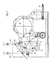
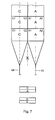
- Fig. 1 shows a schematic side view of a folder.
- This folder has two enemas 01; 02 for multilayer material webs 03; 04, in particular paper webs 03; 04, which in the following as inner or outer web 03; 04 are called.
- Both tracks 03; 04 each pass through a pair of draw rollers 06; 07 for adjusting their tension and meet a transport cylinder 11 in the amount of cutting gaps 08; 09 between the transport cylinder 11 on the one hand and one of Cutting cylinder 12; 13 on the other hand.
- the tracks contact 03; 04 preferably each first the transport cylinder 11 and then the cutting cylinder 12; 13, ie the tracks 03; 04 wrap around first the transport cylinder 11 and then the cutting cylinder 12; 13th
- Each cutting cylinder 12 ′ has a circumference corresponding to at least one, preferably two lengths of the webs 03; 04 to be produced signatures and carries two cutting blades 14th
- the circumference of the transport cylinder 11 corresponds to more than five, in particular seven lengths of the signature. Seven at equal intervals in the peripheral surface of the transport cylinder 11 inserted counter cutting strips, z. B. hard rubber strips, serve as an abutment 15, each with the cutting of the webs 03; 04 cooperate with a cutting blade 14. Each of the abutment 15 is adjacent to a holding device 16, z. B. spur strip 16 with extendable puncture needles 23 (see Fig. 2 to 5 ) is arranged on the transport cylinder 11.
- the rotation of the two cutting cylinders 12; 13 is synchronized so that a cutting blade 14 of the cutting cylinder 13 always at the same time with a small gap between two successive, cut from the inner web 03 signatures and an abutment 15 passes through the cutting gap 09.
- Different techniques for creating this gap will be discussed below with reference to the Fig. 2 to 5 explained.
- the angular distance between the two cutting gaps 08; 09 is about 50 ° in the example shown here. This angular distance may differ from the angular distance of the spur strips 16 from each other (51.5 °) or a multiple thereof, so not at the two cutting gaps 08; 09 is cut simultaneously; even a half-integer multiple of this value is unfavorable from the viewpoint of vibration avoidance.
- each puncture strip 16 After passing through the cutting gap 09 each puncture strip 16 carries a total product, which is composed in each case of a cut off from the inner web 03 signature and a truncated from the outer web 04 signature. With each revolution of the transport cylinder 11 seven products are produced, as well as when both tracks 03; 04 in a conventional manner via a common inlet 01; 02 would be supplied. However, since the cutting of each signature on two cutting steps at the cutting gaps 08; 09 distributed, the force to be applied in each cutting step is lower, and a satisfactory synchronization of the machine is easier to maintain.
- FIG. 1 On the transport cylinder 11 are also seven in the FIG. 1 Folding blades not shown mounted, which are each extended upon reaching a gap 17 between the transport cylinder 11 and a jaw cylinder 18 to pass the transported on the transport cylinder 11 signatures to the jaw cylinder 18 in a conventional manner and to fold.
- the folded products are transferred from the jaw cylinder 18 to a paddle wheel 19 and are designed by the latter onto a conveyor belt 21.
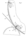
- Fig. 2 shows a detailed view of the cutting gap 09 and its surroundings according to a first embodiment of the invention.
- Two of the seven puncture strips 16 of the transport cylinder 11 are in the Fig. 2 shown and with spur strips 16 '; Both are respectively pivotable about a shaft 22 and carry puncturing needles 23 which are oriented so that their protruding from the circumference of the transport cylinder 11 tip is further away from the center of the shaft 22 as their lying within the transport cylinder 11 base
- the puncturing needles 23 of the spur strip 16 ' are in a comparatively far extended position, in which they have previously also passed through the cutting gap 08. This same position is drawn in dashed lines at the location of the spur strip 16 ".
- the spur strip 16 is pivoted back into the interior of the transport cylinder 11. This pivoting movement causes a displacement of the point of intersection between the sprocket pins 23 and the surface of the transport cylinder 11 counter to the direction of rotation of the sprocket 16" Signature 24 compared to the position in which it was cut at the cutting gap 08 of the inner web 03, slightly shifted against the direction of rotation of the transport cylinder 11. After passing through the cutting gap 09, the spur strip 16 "returns to the position shown in dashed lines or even moves into an even further extended position so as to cancel out or overcompensate the backward shift of the signature 24.
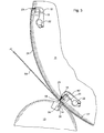
- Fig. 3 shows an alternative embodiment of the transport cylinder 11 and the Cutting cylinder 13 in a partial section analogous to that of Fig. 2 ,
- the cutting cylinder 13 has for each cutting blade 14 on its outer circumference projecting bar 28 which passes through the cutting gap 09 in each case shortly before the associated cutting blade 14.
- a complementarily shaped groove 29 on the transport cylinder 11 is opposite the bar 28 at each nip passage, so that the bar 28 pushes a trailing edge portion of the 27 cut off from the inner web signature 27 and the outer web 04 in the groove 29.
- the spur strip 16 "pivots outwards again after its passage through the cutting gap 09 to generate the gap 26.
- a third embodiment is in Fig. 4 again shown with reference to a partial section of the transport cylinder 11 and the cutting cylinder 13.
- the cutting cylinder 13 is identical to that of Fig. 2
- the transport cylinder 11 differs by the arrangement of the shafts 22 about which the spurs 16 are pivotable. While in the embodiments of Fig. 2 and 3 These waves 22 are in the direction of rotation of the transport cylinder 11 in front of the point needles 23, they are in the embodiment of Fig. 4 arranged behind this.
- the orientation of the puncturing needles 23 with respect to the surface of the transport cylinder 11 is the same in all cases, they are slightly inclined against the surface normal in the direction of rotation of the transport cylinder 11 forward, so that acting on a spiked on the point needles 23 material tension this against the Surface of the transport cylinder 11 holds pressed.
- the outward movement of the puncturing needles 23 causes a shift of their intersection with the circumference of the transport cylinder 11 against the direction of movement and thus a departure of the leading edge of the held by the spur strip 16 ** signature 24 from the point of impact of the cutting blade 14 on the abutment 15th
- the puncturing needles 23 of the spur strip 16 *** are once again pulled back into the transport cylinder 11 in order to advance the signature 27 they hold in the circumferential direction and thus open the gap 26 at the level of the abutment 15
- a fourth embodiment of the cutting device is in Fig. 5 turn in a to Fig. 4 analog view shown.
- each of these segments 32 *, 32 **, ... is composed of a plurality of flexible blades, which are arranged in the axial direction of the transport cylinder 11 side by side and spaced by gaps. These columns are used in the transfer of the finished cut signatures 24; 27 at the jaw cylinder 18 each as outlet openings for prongs of a (not shown) folding blade.
- the ends of the slats are each anchored in the circumferential direction of the transport cylinder 11 slidable head strips 33.
- the segment 32 * is in a configuration in which the course of its lamellae corresponds to the cylindrical shape of the transport cylinder 11. After passage of such a segment 32 * through the cutting gap 09 whose head strips 33 toward each other shifted so that its lamellae, as shown on the segment 32 ** form over the circumference of the transport cylinder 11 extending projection. As a result of this projection, the distance between the pin punctures 16 ** and 16 *** measured along the surface of the transport cylinder 11 is greater than that between the puncture strips 16 * and 16 **, the latter corresponds to the length of the signatures 24 generated at the cutting gap 08; 27. The bulge of the segment 32 ** therefore causes between the signatures 24 and 27, the gap 26 is formed, in which the cutting blade 14 of the cutting cylinder 13 can engage.
- the second cross-cutting device 11, 13 is disposed on the circumference of the transport cylinder 11 phase-shifted cutting.
- the section of the first cross-cutting device 11, 12 on the transport cylinder 11 takes place next to, in particular 10 mm next to, the other section of the second cross-cutting device 11, 13th
- the first and second cross-cutting devices 11, 13 are arranged in the circumferential direction on the transport cylinder 11.
- a further transport cylinder for transferring the signatures can be connected downstream in all modes of operation, which in turn can be followed by a jaw cylinder or a belt system.
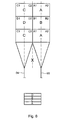
- each of the tracks 03; 04 same pattern A and B in succession, ie in the transport direction.
- These patterns A and B are preferably printed with at least one forme cylinder of a printing unit which carries two identical patterns A or B on the circumference.
- the tracks 03; 04 are superimposed, so that signatures arise with superimposed patterns A and B, which pass in each case in the gap 17 to the subsequent Falklappenzylinder 18.
- the transport cylinder 11 not necessarily have an odd-numbered division, but may also have an even division, preferably greater than 4 or 6.
- Patterns A, B, C, D preferably each designate two newspaper pages, A1, A2; B1, B2; C1, C2; D1, D2 each denote a newspaper page.
- Bahn 03 is at least one track 03; 04, but below is preferably one of several superimposed tracks 03; 04 existing strand to understand.
- the tracks 03; 04 are each printed with printing cylinders of printing units that either wear a pattern A or B on the circumference (single circumference) or two patterns A and B on the circumference (double circumference) wear.
- double-circumference form cylinder two similar patterns A, A and B, B or two different patterns A, B may be circumferentially arranged.
- the tracks carry 03; 04 in a first mode of operation one behind the other same pattern A and C and there are formed on the transport cylinder 11 in a row at each revolution the same products and delivered directly to the subsequent jaw cylinder 18.
Landscapes
- Folding Of Thin Sheet-Like Materials, Special Discharging Devices, And Others (AREA)
- Treatment Of Fiber Materials (AREA)
- Nonmetal Cutting Devices (AREA)
- Machines For Laying And Maintaining Railways (AREA)
Claims (19)
- Dispositif de coupe, pour le découpage transversal au moins d'une bande de matériau (03 ; 04) avec un cylindre de transport (11), le cylindre de transport (11) étant disposé en formant un premier intervalle de découpage (08) avec un premier dispositif de découpage transversal (11, 12), le cylindre de transport (11) étant disposé en formant en plus un deuxième intervalle de découpage (09) avec un deuxième dispositif de découpage transversal (11, 13), le premier dispositif de découpage transversal (11, 12) et le deuxième dispositif de découpage transversal (11, 13) étant disposés de manière décalée en direction périphérique sur le cylindre de transport (11), caractérisé en ce que le cylindre de transport (11) est réalisé sous forme de cylindre à lames de pliage.
- Dispositif de coupe selon la revendication 1, caractérisé en ce que le dispositif de découpage transversal (11, 12 ; 11, 13) présente chaque fois un cylindre de découpage (12 ; 13).
- Dispositif de coupe selon la revendication 1, caractérisé en ce que le cylindre de transport (11) présente des contre-appuis (15) pour lame de découpage (14).
- Dispositif de coupe selon la revendication 1, caractérisé en ce que le premier dispositif de découpage transversal (11, 12) est disposé en séparant une première bande de matériau (03), et le deuxième dispositif de découpage transversal (11, 13) est disposé en séparant une deuxième bande de matériau (04).
- Dispositif de coupe selon la revendication 1, caractérisé en ce que le deuxième dispositif de découpage transversal (11, 13) est disposé en découpant avec un déphasage, sur la périphérie du cylindre de transport (11).
- Dispositif de coupe selon la revendication 5, caractérisé en ce que, sur le cylindre de transport (11), la coupure du premier dispositif de découpage transversal (11, 12) s'effectue peu à côté, en particulier à moins de 10 mm, à côté d'une coupe du deuxième dispositif de découpage transversal (11, 13).
- Dispositif de coupe selon la revendication 1, caractérisé en ce que le cylindre de transport (11) et un premier cylindre de découpage (12) sont susceptibles de tourner conjointement, et délimitent un premier intervalle de découpage (08), à travers lequel s'étend un premier chemin de transport pour une première bande de matériau (03) à découper, le premier cylindre de découpage (12) portant au moins une lame de découpage (14) pour découper une première signature (24) à partir de la première bande de matériau (03) lors du passage de la lame de découpage (14) à travers le premier intervalle de découpage (08), en ce qu'un deuxième chemin de transport pour une deuxième bande de matériau (04) à découper, sur le cylindre de transport (11), arrive sur le premier chemin de transport, et en ce qu'un deuxième cylindre de découpage (13) est susceptible de tourner conjointement avec le cylindre de transport (11) et délimite, avec celui-ci, un deuxième intervalle de découpage (09), à travers lequel s'étendent les deux chemins de transport, le deuxième cylindre de découpage (13) portant au moins une lame de découpage (14) pour découper une deuxième signature (27) à partir de la deuxième bande de matériau (04), lors du passage de la lame de découpage (14) à travers le deuxième intervalle de découpage (09).
- Dispositif de coupe selon la revendication 7, caractérisé en ce que la rotation des deux cylindres de découpage (12 ; 13) est synchronisée de manière que la deuxième lame de découpage (14), lors de son passage par le deuxième intervalle de découpage (09) arrive sur une découpe, produite par la première lame de découpage (14), dans la première bande de matériau (03).
- Dispositif de coupe selon la revendication 8, caractérisé par des moyens (16 ; 16' ; 16", 16* ; 16** ; 16*** ; 32* ; 32**, 33) pour séparer les unes des autres les arêtes de coupe produites par la première lame de coupe (14) lors du découpage de la première bande de matériau (03) sur celle-ci.
- Dispositif de coupe selon la revendication 9, caractérisé en ce que les moyens (16 ; 16' ; 16", 16* ; 16** ; 16*** ; 32* ; 32**, 33) pour séparer les arêtes de coupe comprennent un dispositif de maintien (16* ; 16**), pour maintenir la première signature (24) découpée et pour déplacer la première signature (24) à l'encontre de la direction de transport, avant atteinte du deuxième intervalle de découpage (09).
- Dispositif de coupe selon la revendication 9 ou 10, caractérisé en ce que les moyens (16 ; 16' ; 16", 16* ; 16** ; 16*** ; 32* ; 32**, 33) pour séparer les arêtes de coupe comprennent un dispositif de maintien (16* ; 16**), pour maintenir la deuxième signature (27) découpée et pour déplacer la deuxième signature (27) dans la direction de transport, après passage par le deuxième intervalle de découpage (09).
- Dispositif de coupe selon la revendication 9, 10 ou 11, caractérisé en ce que le dispositif de maintien (16 ; 16' ; 16", 16* ; 16** ; 16***) est une bande à ardillons de pointure (16 ; 16' ; 16", 16* ; 16** ; 16***).
- Dispositif de coupe selon la revendication 12, caractérisé en ce que la bande à ardillons de pointure (16 ; 16' ; 16", 16* ; 16** ; 16***) portant les ardillons de pointure (23) est susceptible de pivoter autour d'un axe (22), et en ce que les ardillons de pointure (23) croisent la périphérie du cylindre de transport (11), en un emplacement, variable de manière correspondante à la position en pivotement de la bande à ardillons de pointure (16 ; 16*).
- Dispositif de coupe selon la revendication 11 et la revendication 12, caractérisé en ce que la bande à ardillons de pointure (16 ; 16' ; 16", 16* ; 16** ; 16***) portant des ardillons de pointure (23) est susceptible de pivoter autour d'un arbre (22), et en ce que les pointes des ardillons de pointure (23) présentent, vis à vis de l'arbre (22), un plus grand espacement que leurs bases.
- Dispositif de coupe selon l'une des revendications 9 à 14, caractérisé en ce que les moyens (16 ; 16' ; 16", 16* ; 16** ; 16*** ; 32* ; 32**, 33) pour séparer les arêtes de coupe comprennent un segment (32 ; 32* ; 32**), déplaçable radialement, du cylindre de transport et un dispositif de commande pour entraîner un mouvement de déploiement du segment (32 ; 32* ; 32**) après passage par le deuxième intervalle de découpage (09).
- Dispositif de coupe selon l'une des revendications 9 à 15, caractérisé en ce que les moyens (16 ; 16' ; 16", 16* ; 16** ; 16*** ; 32* ; 32**, 33) pour séparer les arêtes de coupe comprennent une cannelure (29) réalisée sur le cylindre de transport (11) et une languette (28), coopérant avec la cannelure (29), sur le deuxième cylindre de découpage (13).
- Dispositif de coupe selon la revendication 1, caractérisé en ce que la circonférence du cylindre de transport (11) fait au moins cinq, de préférence sept longueurs de signature.
- Dispositif de coupe selon l'une des revendications précédentes, caractérisé en ce qu'une entrée (01 ; 02) est associée à chaque bande de matériau (03 ; 04).
- Dispositif de coupe selon la revendication 1, caractérisé en ce que les bandes (03 ; 04) enlacent d'abord le cylindre de transport (11) et entrent en contact, ensuite, avec un cylindre de découpage (12 ; 13) respectif.
Priority Applications (1)
| Application Number | Priority Date | Filing Date | Title |
|---|---|---|---|
| EP20080171447 EP2030935B1 (fr) | 2002-03-04 | 2003-02-28 | Dispositif de coupe transversale d'au moins une bande de matériau |
Applications Claiming Priority (3)
| Application Number | Priority Date | Filing Date | Title |
|---|---|---|---|
| DE2002109190 DE10209190B4 (de) | 2002-03-04 | 2002-03-04 | Schneidvorrichtung zum Querschneiden wenigstens einer Materialbahn |
| DE10209190 | 2002-03-04 | ||
| PCT/DE2003/000673 WO2003074402A1 (fr) | 2002-03-04 | 2003-02-28 | Dispositif de coupe transversale d'au moins une bande de materiau |
Related Child Applications (2)
| Application Number | Title | Priority Date | Filing Date |
|---|---|---|---|
| EP20080171447 Division EP2030935B1 (fr) | 2002-03-04 | 2003-02-28 | Dispositif de coupe transversale d'au moins une bande de matériau |
| EP08171447.9 Division-Into | 2008-12-12 |
Publications (2)
| Publication Number | Publication Date |
|---|---|
| EP1480903A1 EP1480903A1 (fr) | 2004-12-01 |
| EP1480903B1 true EP1480903B1 (fr) | 2010-03-17 |
Family
ID=27770928
Family Applications (2)
| Application Number | Title | Priority Date | Filing Date |
|---|---|---|---|
| EP20030743293 Expired - Lifetime EP1480903B1 (fr) | 2002-03-04 | 2003-02-28 | Dispositif de coupe transversale d'au moins une bande de materiau |
| EP20080171447 Expired - Lifetime EP2030935B1 (fr) | 2002-03-04 | 2003-02-28 | Dispositif de coupe transversale d'au moins une bande de matériau |
Family Applications After (1)
| Application Number | Title | Priority Date | Filing Date |
|---|---|---|---|
| EP20080171447 Expired - Lifetime EP2030935B1 (fr) | 2002-03-04 | 2003-02-28 | Dispositif de coupe transversale d'au moins une bande de matériau |
Country Status (9)
| Country | Link |
|---|---|
| US (1) | US7351189B2 (fr) |
| EP (2) | EP1480903B1 (fr) |
| JP (1) | JP4032029B2 (fr) |
| CN (1) | CN1283535C (fr) |
| AT (2) | ATE460376T1 (fr) |
| AU (1) | AU2003227014A1 (fr) |
| DE (3) | DE10209190B4 (fr) |
| RU (1) | RU2283269C2 (fr) |
| WO (1) | WO2003074402A1 (fr) |
Families Citing this family (6)
| Publication number | Priority date | Publication date | Assignee | Title |
|---|---|---|---|---|
| DE102006042592B4 (de) * | 2006-09-11 | 2009-04-09 | Koenig & Bauer Aktiengesellschaft | Falzapparat |
| DE102007025797B4 (de) * | 2007-06-02 | 2009-02-26 | Koenig & Bauer Aktiengesellschaft | Falzapparat |
| DE102013017224A1 (de) * | 2013-10-17 | 2015-04-23 | Manroland Web Systems Gmbh | Verfahren und Vorrichtung zum Bearbeiten einer Bedruckstoffbahn |
| EP3207803A1 (fr) * | 2016-02-17 | 2017-08-23 | Haas Food Equipment GmbH | Procédé et dispositif de coupe de sortie de pâte par une machine à extrusion |
| DE102018108982A1 (de) * | 2018-04-16 | 2019-10-17 | Manroland Goss Web Systems Gmbh | Klemmhebel zum Anbringen von Bearbeitungswerkzeugen an einem drehbar gelagerten Element einer Druckmaschine |
| CN111055316B (zh) * | 2020-01-23 | 2025-07-01 | 广东金玉兰包装机械有限公司 | 一种除纸屑刀片及其切割纸盒机构 |
Family Cites Families (19)
| Publication number | Priority date | Publication date | Assignee | Title |
|---|---|---|---|---|
| DE239837C (fr) | ||||
| US2891791A (en) * | 1955-12-19 | 1959-06-23 | Miehle Goss Dexter Inc | Jaw folding mechanism |
| DE2846191C3 (de) * | 1978-10-24 | 1981-08-13 | Koenig & Bauer AG, 8700 Würzburg | Falzapparat für Rollenrotationsdruckmaschinen |
| DE3139117C1 (de) * | 1981-10-01 | 1983-04-21 | M.A.N.- Roland Druckmaschinen AG, 6050 Offenbach | Variabler Falzapparat mit einem Schneidzylinderpaarund einem unterhalb diesem angeordneten Abreisswalzenpaar |
| DE3151283C1 (de) * | 1981-12-24 | 1983-04-21 | M.A.N.- Roland Druckmaschinen AG, 6050 Offenbach | Falzapparat |
| DE3527710A1 (de) * | 1985-08-02 | 1987-02-12 | Roland Man Druckmasch | Falzapparat zum querfalzen zugeschnittener druckexemplare |
| US4754959A (en) * | 1985-08-02 | 1988-07-05 | M.A.N. Roland Druckmaschinen Aktiengesellschaft | Folding apparatus for transverse folding and transporting of two types of printed substrates |
| DE3637110C1 (de) * | 1986-10-31 | 1988-05-19 | Heidelberger Druckmasch Ag | Vorrichtung zum Schneiden und Aufteilen eines kontinuierlichen Stroms von Druckprodukten |
| SU1652092A1 (ru) * | 1988-11-30 | 1991-05-30 | Украинский Научно-Исследовательский Институт Полиграфической Промышленности | Устройство дл рубки бумажного полотна фальцевального аппарата рулонных печатных машин |
| US5024128A (en) * | 1989-02-21 | 1991-06-18 | Campbell Jr Gaines P | Sheeter for web fed printing press |
| DE4316134C2 (de) * | 1993-05-13 | 1997-03-13 | Heidelberger Druckmasch Ag | Verfahren zur Querfalzung von Bahnen sowie Falzapparat zur Durchführung des Verfahrens |
| DE9320814U1 (de) | 1993-12-24 | 1995-02-09 | Koenig & Bauer AG, 97080 Würzburg | Vorrichtung zum Herstellen von Falzprodukten |
| DE4344362C2 (de) * | 1993-12-24 | 1998-02-26 | Koenig & Bauer Albert Ag | Vorrichtung zum Herstellen von Falzprodukten |
| JPH10194588A (ja) | 1997-01-07 | 1998-07-28 | Toshiba Mach Co Ltd | 印刷機の2種折り装置 |
| US7338425B1 (en) * | 2000-01-12 | 2008-03-04 | Goss International Americas, Inc. | Variable length cutting device |
| DE10116346B4 (de) * | 2001-04-02 | 2006-03-02 | Koenig & Bauer Ag | Falzapparat |
| US6733431B2 (en) * | 2001-09-19 | 2004-05-11 | Heidelberger Druckmaschinen Ag | Device and method for folding newspapers with flexible inserting position |
| DE10209214B4 (de) * | 2002-03-04 | 2004-03-25 | Koenig & Bauer Ag | Schneidvorrichtung |
| DE10326976B4 (de) * | 2003-06-12 | 2011-12-15 | Manroland Ag | Schneidzylinder zum Querschneiden einer Bedruckstoffbahn in einer Rotationsdruckmaschine |
-
2002
- 2002-03-04 DE DE2002109190 patent/DE10209190B4/de not_active Expired - Fee Related
-
2003
- 2003-02-28 US US10/505,872 patent/US7351189B2/en not_active Expired - Fee Related
- 2003-02-28 EP EP20030743293 patent/EP1480903B1/fr not_active Expired - Lifetime
- 2003-02-28 RU RU2004120788A patent/RU2283269C2/ru not_active IP Right Cessation
- 2003-02-28 AT AT08171447T patent/ATE460376T1/de active
- 2003-02-28 AU AU2003227014A patent/AU2003227014A1/en not_active Abandoned
- 2003-02-28 EP EP20080171447 patent/EP2030935B1/fr not_active Expired - Lifetime
- 2003-02-28 CN CNB038040824A patent/CN1283535C/zh not_active Expired - Fee Related
- 2003-02-28 DE DE50312508T patent/DE50312508D1/de not_active Expired - Lifetime
- 2003-02-28 JP JP2003572882A patent/JP4032029B2/ja not_active Expired - Fee Related
- 2003-02-28 DE DE50312521T patent/DE50312521D1/de not_active Expired - Lifetime
- 2003-02-28 WO PCT/DE2003/000673 patent/WO2003074402A1/fr not_active Ceased
- 2003-02-28 AT AT03743293T patent/ATE461148T1/de active
Also Published As
| Publication number | Publication date |
|---|---|
| CN1633387A (zh) | 2005-06-29 |
| DE10209190B4 (de) | 2004-03-04 |
| EP1480903A1 (fr) | 2004-12-01 |
| US7351189B2 (en) | 2008-04-01 |
| JP4032029B2 (ja) | 2008-01-16 |
| DE50312508D1 (de) | 2010-04-22 |
| ATE460376T1 (de) | 2010-03-15 |
| DE10209190A1 (de) | 2003-09-25 |
| EP2030935B1 (fr) | 2010-03-10 |
| US20050160889A1 (en) | 2005-07-28 |
| RU2283269C2 (ru) | 2006-09-10 |
| EP2030935A1 (fr) | 2009-03-04 |
| JP2005519007A (ja) | 2005-06-30 |
| AU2003227014A1 (en) | 2003-09-16 |
| DE50312521D1 (de) | 2010-04-29 |
| WO2003074402B1 (fr) | 2004-03-04 |
| WO2003074402A1 (fr) | 2003-09-12 |
| RU2004120788A (ru) | 2005-05-27 |
| ATE461148T1 (de) | 2010-04-15 |
| CN1283535C (zh) | 2006-11-08 |
Similar Documents
| Publication | Publication Date | Title |
|---|---|---|
| EP0859733B1 (fr) | Procede et dispositif permettant de produire des journaux a couches multiples avec une partie de format tabloide | |
| EP2039640B1 (fr) | Dispositif et procédé de production d'un produit d'impression et produit d'impression | |
| DE10116346B4 (de) | Falzapparat | |
| EP1480903B1 (fr) | Dispositif de coupe transversale d'au moins une bande de materiau | |
| EP1922276B1 (fr) | Appareil de pliage | |
| EP1483189B1 (fr) | Dispositif de coupe | |
| DE19927920A1 (de) | Schneideinrichtung im Falzapparat einer Rotationsdruckmaschine und Falzapparat mit einer solchen Schneideinrichtung | |
| EP1480902B1 (fr) | Dispositif de transport | |
| EP0222150B1 (fr) | Plieuse à lames engageantes | |
| EP1620343B1 (fr) | Appareil de pliage roues doté d'un dispositif de coupe pour couper en travers au moins une bande de matériau | |
| DE102006057453B4 (de) | Falzapparat | |
| EP1802466A2 (fr) | Procede et imprimante pour produire des produits imprimes avec plusieurs livres | |
| DE4140365C2 (de) | Vorrichtung zum Beschneiden einer Materialbahn | |
| EP4282657A1 (fr) | Plieuse d'une machine d'impression offset á bobines et machine d'impression offset á bobines | |
| DE102014222387B4 (de) | Verfahren zur Herstellung eines Druckproduktes sowie Druckprodukt | |
| DE102016216429B4 (de) | Druckprodukt, Verfahren und Rollendruckmaschine zur Herstellung eines Druckproduktes | |
| DE102014207835B4 (de) | Verfahren und Druckmaschine zur Herstellung von Druckprodukten | |
| EP3398891B1 (fr) | Dispositif de production de collections d'imprimés en forme de feuilles, et appareil correspondant de pliage de collections d'imprimés en forme de feuilles | |
| DE102012203102B4 (de) | Rollendruckmaschine sowie Verfahren zum Betrieb einer Rollendruckmaschine | |
| DE102004005807A1 (de) | Falzapparat | |
| DE9313481U1 (de) | Einrichtung zum Übereinanderlegen | |
| DE102011102542A1 (de) | Falzwerk | |
| DE9313480U1 (de) | Einrichtung zum Aufeinanderlegen |
Legal Events
| Date | Code | Title | Description |
|---|---|---|---|
| PUAI | Public reference made under article 153(3) epc to a published international application that has entered the european phase |
Free format text: ORIGINAL CODE: 0009012 |
|
| 17P | Request for examination filed |
Effective date: 20040621 |
|
| AK | Designated contracting states |
Kind code of ref document: A1 Designated state(s): AT BE BG CH CY CZ DE DK EE ES FI FR GB GR HU IE IT LI LU MC NL PT SE SI SK TR |
|
| AX | Request for extension of the european patent |
Extension state: AL LT LV MK RO |
|
| 17Q | First examination report despatched |
Effective date: 20081128 |
|
| GRAP | Despatch of communication of intention to grant a patent |
Free format text: ORIGINAL CODE: EPIDOSNIGR1 |
|
| GRAS | Grant fee paid |
Free format text: ORIGINAL CODE: EPIDOSNIGR3 |
|
| GRAA | (expected) grant |
Free format text: ORIGINAL CODE: 0009210 |
|
| AK | Designated contracting states |
Kind code of ref document: B1 Designated state(s): AT BE BG CH CY CZ DE DK EE ES FI FR GB GR HU IE IT LI LU MC NL PT SE SI SK TR |
|
| REG | Reference to a national code |
Ref country code: GB Ref legal event code: FG4D Free format text: NOT ENGLISH |
|
| REG | Reference to a national code |
Ref country code: CH Ref legal event code: EP |
|
| REG | Reference to a national code |
Ref country code: IE Ref legal event code: FG4D |
|
| REF | Corresponds to: |
Ref document number: 50312521 Country of ref document: DE Date of ref document: 20100429 Kind code of ref document: P |
|
| REG | Reference to a national code |
Ref country code: NL Ref legal event code: VDEP Effective date: 20100317 |
|
| PG25 | Lapsed in a contracting state [announced via postgrant information from national office to epo] |
Ref country code: FI Free format text: LAPSE BECAUSE OF FAILURE TO SUBMIT A TRANSLATION OF THE DESCRIPTION OR TO PAY THE FEE WITHIN THE PRESCRIBED TIME-LIMIT Effective date: 20100317 Ref country code: SI Free format text: LAPSE BECAUSE OF FAILURE TO SUBMIT A TRANSLATION OF THE DESCRIPTION OR TO PAY THE FEE WITHIN THE PRESCRIBED TIME-LIMIT Effective date: 20100317 |
|
| REG | Reference to a national code |
Ref country code: IE Ref legal event code: FD4D |
|
| PG25 | Lapsed in a contracting state [announced via postgrant information from national office to epo] |
Ref country code: SE Free format text: LAPSE BECAUSE OF FAILURE TO SUBMIT A TRANSLATION OF THE DESCRIPTION OR TO PAY THE FEE WITHIN THE PRESCRIBED TIME-LIMIT Effective date: 20100317 Ref country code: NL Free format text: LAPSE BECAUSE OF FAILURE TO SUBMIT A TRANSLATION OF THE DESCRIPTION OR TO PAY THE FEE WITHIN THE PRESCRIBED TIME-LIMIT Effective date: 20100317 Ref country code: EE Free format text: LAPSE BECAUSE OF FAILURE TO SUBMIT A TRANSLATION OF THE DESCRIPTION OR TO PAY THE FEE WITHIN THE PRESCRIBED TIME-LIMIT Effective date: 20100317 Ref country code: CY Free format text: LAPSE BECAUSE OF FAILURE TO SUBMIT A TRANSLATION OF THE DESCRIPTION OR TO PAY THE FEE WITHIN THE PRESCRIBED TIME-LIMIT Effective date: 20100317 Ref country code: GR Free format text: LAPSE BECAUSE OF FAILURE TO SUBMIT A TRANSLATION OF THE DESCRIPTION OR TO PAY THE FEE WITHIN THE PRESCRIBED TIME-LIMIT Effective date: 20100618 Ref country code: ES Free format text: LAPSE BECAUSE OF FAILURE TO SUBMIT A TRANSLATION OF THE DESCRIPTION OR TO PAY THE FEE WITHIN THE PRESCRIBED TIME-LIMIT Effective date: 20100628 |
|
| PG25 | Lapsed in a contracting state [announced via postgrant information from national office to epo] |
Ref country code: CZ Free format text: LAPSE BECAUSE OF FAILURE TO SUBMIT A TRANSLATION OF THE DESCRIPTION OR TO PAY THE FEE WITHIN THE PRESCRIBED TIME-LIMIT Effective date: 20100317 Ref country code: BG Free format text: LAPSE BECAUSE OF FAILURE TO SUBMIT A TRANSLATION OF THE DESCRIPTION OR TO PAY THE FEE WITHIN THE PRESCRIBED TIME-LIMIT Effective date: 20100617 Ref country code: SK Free format text: LAPSE BECAUSE OF FAILURE TO SUBMIT A TRANSLATION OF THE DESCRIPTION OR TO PAY THE FEE WITHIN THE PRESCRIBED TIME-LIMIT Effective date: 20100317 |
|
| PLBE | No opposition filed within time limit |
Free format text: ORIGINAL CODE: 0009261 |
|
| STAA | Information on the status of an ep patent application or granted ep patent |
Free format text: STATUS: NO OPPOSITION FILED WITHIN TIME LIMIT |
|
| PG25 | Lapsed in a contracting state [announced via postgrant information from national office to epo] |
Ref country code: PT Free format text: LAPSE BECAUSE OF FAILURE TO SUBMIT A TRANSLATION OF THE DESCRIPTION OR TO PAY THE FEE WITHIN THE PRESCRIBED TIME-LIMIT Effective date: 20100719 Ref country code: DK Free format text: LAPSE BECAUSE OF FAILURE TO SUBMIT A TRANSLATION OF THE DESCRIPTION OR TO PAY THE FEE WITHIN THE PRESCRIBED TIME-LIMIT Effective date: 20100317 Ref country code: IE Free format text: LAPSE BECAUSE OF FAILURE TO SUBMIT A TRANSLATION OF THE DESCRIPTION OR TO PAY THE FEE WITHIN THE PRESCRIBED TIME-LIMIT Effective date: 20100317 |
|
| 26N | No opposition filed |
Effective date: 20101220 |
|
| PG25 | Lapsed in a contracting state [announced via postgrant information from national office to epo] |
Ref country code: IT Free format text: LAPSE BECAUSE OF FAILURE TO SUBMIT A TRANSLATION OF THE DESCRIPTION OR TO PAY THE FEE WITHIN THE PRESCRIBED TIME-LIMIT Effective date: 20100317 |
|
| PGFP | Annual fee paid to national office [announced via postgrant information from national office to epo] |
Ref country code: CH Payment date: 20110225 Year of fee payment: 9 |
|
| BERE | Be: lapsed |
Owner name: KOENIG & BAUER A.G. Effective date: 20110228 |
|
| PG25 | Lapsed in a contracting state [announced via postgrant information from national office to epo] |
Ref country code: MC Free format text: LAPSE BECAUSE OF NON-PAYMENT OF DUE FEES Effective date: 20110228 |
|
| PG25 | Lapsed in a contracting state [announced via postgrant information from national office to epo] |
Ref country code: BE Free format text: LAPSE BECAUSE OF NON-PAYMENT OF DUE FEES Effective date: 20110228 |
|
| REG | Reference to a national code |
Ref country code: CH Ref legal event code: PL |
|
| PG25 | Lapsed in a contracting state [announced via postgrant information from national office to epo] |
Ref country code: CH Free format text: LAPSE BECAUSE OF NON-PAYMENT OF DUE FEES Effective date: 20120229 Ref country code: LI Free format text: LAPSE BECAUSE OF NON-PAYMENT OF DUE FEES Effective date: 20120229 |
|
| REG | Reference to a national code |
Ref country code: AT Ref legal event code: MM01 Ref document number: 461148 Country of ref document: AT Kind code of ref document: T Effective date: 20110228 |
|
| PG25 | Lapsed in a contracting state [announced via postgrant information from national office to epo] |
Ref country code: AT Free format text: LAPSE BECAUSE OF NON-PAYMENT OF DUE FEES Effective date: 20110228 |
|
| PG25 | Lapsed in a contracting state [announced via postgrant information from national office to epo] |
Ref country code: LU Free format text: LAPSE BECAUSE OF NON-PAYMENT OF DUE FEES Effective date: 20110228 |
|
| PG25 | Lapsed in a contracting state [announced via postgrant information from national office to epo] |
Ref country code: TR Free format text: LAPSE BECAUSE OF FAILURE TO SUBMIT A TRANSLATION OF THE DESCRIPTION OR TO PAY THE FEE WITHIN THE PRESCRIBED TIME-LIMIT Effective date: 20100317 |
|
| PG25 | Lapsed in a contracting state [announced via postgrant information from national office to epo] |
Ref country code: HU Free format text: LAPSE BECAUSE OF FAILURE TO SUBMIT A TRANSLATION OF THE DESCRIPTION OR TO PAY THE FEE WITHIN THE PRESCRIBED TIME-LIMIT Effective date: 20100317 |
|
| REG | Reference to a national code |
Ref country code: FR Ref legal event code: PLFP Year of fee payment: 13 |
|
| PGFP | Annual fee paid to national office [announced via postgrant information from national office to epo] |
Ref country code: DE Payment date: 20150318 Year of fee payment: 13 |
|
| PGFP | Annual fee paid to national office [announced via postgrant information from national office to epo] |
Ref country code: FR Payment date: 20150223 Year of fee payment: 13 Ref country code: GB Payment date: 20150220 Year of fee payment: 13 |
|
| REG | Reference to a national code |
Ref country code: DE Ref legal event code: R119 Ref document number: 50312521 Country of ref document: DE |
|
| GBPC | Gb: european patent ceased through non-payment of renewal fee |
Effective date: 20160228 |
|
| REG | Reference to a national code |
Ref country code: FR Ref legal event code: ST Effective date: 20161028 |
|
| PG25 | Lapsed in a contracting state [announced via postgrant information from national office to epo] |
Ref country code: GB Free format text: LAPSE BECAUSE OF NON-PAYMENT OF DUE FEES Effective date: 20160228 Ref country code: FR Free format text: LAPSE BECAUSE OF NON-PAYMENT OF DUE FEES Effective date: 20160229 Ref country code: DE Free format text: LAPSE BECAUSE OF NON-PAYMENT OF DUE FEES Effective date: 20160901 |