EP1479636A1 - Puffer zum Schaffen einer Schutzzone in einer Aufzugsanlage - Google Patents
Puffer zum Schaffen einer Schutzzone in einer Aufzugsanlage Download PDFInfo
- Publication number
- EP1479636A1 EP1479636A1 EP04011503A EP04011503A EP1479636A1 EP 1479636 A1 EP1479636 A1 EP 1479636A1 EP 04011503 A EP04011503 A EP 04011503A EP 04011503 A EP04011503 A EP 04011503A EP 1479636 A1 EP1479636 A1 EP 1479636A1
- Authority
- EP
- European Patent Office
- Prior art keywords
- elevator car
- counterweight
- elevator
- movable means
- buffer
- Prior art date
- Legal status (The legal status is an assumption and is not a legal conclusion. Google has not performed a legal analysis and makes no representation as to the accuracy of the status listed.)
- Withdrawn
Links
- 239000000872 buffer Substances 0.000 title claims abstract description 161
- 238000007689 inspection Methods 0.000 title 1
- 238000000034 method Methods 0.000 claims abstract description 7
- 230000001681 protective effect Effects 0.000 claims abstract description 7
- 230000003139 buffering effect Effects 0.000 claims description 15
- 238000009434 installation Methods 0.000 claims description 10
- 239000000725 suspension Substances 0.000 claims description 7
- 238000013016 damping Methods 0.000 claims description 3
- 241001441724 Tetraodontidae Species 0.000 description 14
- 230000008901 benefit Effects 0.000 description 4
- 238000013459 approach Methods 0.000 description 2
- 230000008859 change Effects 0.000 description 2
- 239000003795 chemical substances by application Substances 0.000 description 2
- 238000013461 design Methods 0.000 description 2
- 238000011161 development Methods 0.000 description 2
- 230000018109 developmental process Effects 0.000 description 2
- 238000012423 maintenance Methods 0.000 description 2
- 240000003517 Elaeocarpus dentatus Species 0.000 description 1
- 241000196324 Embryophyta Species 0.000 description 1
- 230000006978 adaptation Effects 0.000 description 1
- 238000005452 bending Methods 0.000 description 1
- 238000010276 construction Methods 0.000 description 1
- 230000001419 dependent effect Effects 0.000 description 1
- 230000003993 interaction Effects 0.000 description 1
- 230000008569 process Effects 0.000 description 1
- 230000008439 repair process Effects 0.000 description 1
- 230000001960 triggered effect Effects 0.000 description 1
Images


Classifications
-
- B—PERFORMING OPERATIONS; TRANSPORTING
- B66—HOISTING; LIFTING; HAULING
- B66B—ELEVATORS; ESCALATORS OR MOVING WALKWAYS
- B66B5/00—Applications of checking, fault-correcting, or safety devices in elevators
- B66B5/28—Buffer-stops for cars, cages, or skips
- B66B5/288—Buffer-stops for cars, cages, or skips with maintenance features
-
- B—PERFORMING OPERATIONS; TRANSPORTING
- B66—HOISTING; LIFTING; HAULING
- B66B—ELEVATORS; ESCALATORS OR MOVING WALKWAYS
- B66B5/00—Applications of checking, fault-correcting, or safety devices in elevators
- B66B5/0043—Devices enhancing safety during maintenance
- B66B5/005—Safety of maintenance personnel
Definitions
- the invention relates to an elevator system with a Buffers to create a protection zone.
- a procedure for Creating a protection zone is another object of the Invention.
- Elevator systems are usually with one or more Buffers provided on the floor of an elevator shaft are arranged to the elevator car when driving over the lowest stop position in the elevator train compartment in Downward direction and / or when driving over the top one Stop position in the elevator train bay in the upward direction Stop traversing a given distance.
- This Buffers are usually located below the elevator car and / or the counterweight.
- the shaft head can be arranged above the elevator car.
- the shaft head or the shaft floor can therefore only be used for other purposes to a limited extent.
- at Lift systems without a pit are one of them Standard arrangement of the buffers not possible, because below there is little space in the elevator car.
- a protection zone in the area of the shaft head To be able to create, the elevator car has according to the PCT Patent application for a device on the roof of the Elevator car is attached. This device can be folded up and drives against the shaft ceiling. So becomes a protection zone at the top of the shaft created.
- This PCT patent application is next Considered the state of the art.
- the present invention has for its object a To provide a solution that makes it possible, if necessary a protection zone at the bottom or at the top of one To create elevator shaft.
- the elevator installation according to the invention has a buffer on, the movable means that are in the orbit of the Elevator car can be moved into it, and movable means, which can be moved into the path of the counterweight, includes.
- the movable means in the web of the elevator car are movable, and the movable means in the Path of the counterweight can be moved into it realized, for example, as a single movable part that can be moved between different layers, that it is in both the elevator car train and in the path of the counterweight can be brought. It is also possible the movable means that in the orbit of the Elevator car can be moved in, and the movable Means that move into the path of the counterweight are, each by different, independently to realize moving parts. For example, a first movable part can be arranged on the buffer so that it can be moved into the path of the elevator car, and a second movable part could be arranged on the buffer be that it can move into the path of the counterweight is.
- the movable means can in one Be brought in the position in which they are are arranged that the elevator car and / or that Counterweight with the movable means in one mechanical contact can be brought. It will allows you to choose the Elevator car or the counterweight in a first or in a second predetermined distance above a floor can be supported. The specified first distance and the predetermined second distance can be different, depending on the arrangement and shape of the buffer or the movable Medium. The elevator car and the counterweight can are therefore supported at different heights.
- the movable means are in a normal position the movable means are not in the path of the elevator car and the counterweight. Consequently, the space available for the Elevator car is accessible when restricted movable means are brought into the operating position. Because either the elevator car or the Counterweight each at a predetermined distance can be supported on a floor, the track that the Can drive through elevator car, shortened at both ends. Thus, shelters at both ends of the web are Elevator car created.
- Another embodiment of the buffer according to the invention comprises a buffering element arranged in such a way that it protrudes into the elevator car path when the movable means are brought into the normal position, wherein the buffering element is designed such that the elevator car with the buffering element in one mechanical contact and at a third distance is supported above the ground, which is less than that first predetermined distance.
- This embodiment is also usable as overrun protection, which the elevator car at Driving over a lowest stop position in the downward direction brakes and stops.
- An embodiment of the buffer according to the invention can have a buffering element arranged in this way is that when the movable means are brought into the normal position, wherein the buffering element is designed such that the counterweight with the buffering element in one mechanical contact and at a fourth distance is supported above the ground, which is less than that second predetermined distance.
- This buffer can be used as Overrun protection can be used by the mechanical contact with the counterweight the counterweight decelerates and stops in the downward direction and thus the Elevator car when driving over a top stop position decelerates in the upward direction and stops.
- the buffer can be developed in such a way that a buffering element in the lanes of the elevator car and the Counterweight protrudes when the movable means in the Are brought to normal position.
- This embodiment has the advantage that with a single buffer - depending on the choice of position of the movable means - the elevator car and / or that Counterweight in at least two different ways Distances above a floor can be supported.
- On such buffers can be suitably dimensioned in one pitless elevator system against overrun protection Driving over a lowest stopping position of the elevator car in the downward direction and against driving over a top one Stop position of the elevator car in the upward direction guarantee and additionally - with a suitable Position of the movable means - the creation of temporary Shelters below and above the elevator car enable.
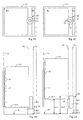
- FIGS. 1A to 1F show a first embodiment of an elevator installation with a buffer 10, according to the invention, in different schematic views and in different states.
- the buffer 10 shown is a buffer for supporting an elevator car 15 above the floor 18 of an elevator shaft 11.
- the elevator car 15 is counterbalanced by means of a suspension element 23.1, for example one or more ropes and / or one or more belts 23 that the elevator car 15 and the counterweight 23 can be moved up and down along the paths V K and V G in the elevator shaft 11.
- the counterweight, the suspension element, the traction sheave for the suspension element, the drive for the traction sheave, the guide rails for the elevator car 15 and the counterweight and the other usual elements of an elevator installation are not shown in FIGS. 1A to 1D.
- the buffer 10 has an elongated extension substantially parallel to the tracks V K or V G of the elevator car 15 or the counterweight 23. It comprises a lower base element 12 and a slimmer upper part 13.
- the buffer further comprises movable means 14 and 14.1 which can be moved out of the upper part 13, as indicated in FIGS. 1C, 1D and 1E.
- a drive device (not shown) is provided which allows the means 14 or 14.1 to be moved between different positions.
- a control device (not shown), which acts on the drive device, allows the positioning of the means 14 or 14.1 to be checked and monitored.
- FIGS. 1A and 1C show the projection K1 of the floor 15.1 of the elevator car 15 and the projection G1 of the underside 23.2 of the counterweight 23, each projected onto the shaft floor, shown.
- the projections K1 and G1 are shown with dashed lines in the areas in which they overlap with the base 12.1 of the base element 12 on the shaft bottom 18.
- the movable means 14 and 14.1 are asymmetrical in the embodiment shown.
- the left trapezoidal part 14 protrudes laterally out of the upper part 13 than the right trapezoidal part 14.1.
- the movable means 14 and 14.1 can be moved at different heights above the shaft floor 18 by the tracks V K and V G :
- An upper part of the movable means 14 is at a height Z1.1 and an upper part of the movable means 14.1 is arranged at a height Z1.2, Z1.2 being larger than Z1.1 (FIGS. 1D and 1E).
- the buffer 10 is shown in FIGS. 1A and 1B in a so-called normal state.
- the movable means 14 and 14.1 are located outside the tracks V K and V G.
- the respective positions which the movable means 14 and 14.1 assume in the normal state of the buffer are referred to below as the normal position.
- the elevator car 15 can move to the landing door 17 of the lower floor without making mechanical contact with the buffer 10.
- the cabin door 16 and the shaft door 17 can be used to get in and out.
- 1C, 1D and 1E show the buffer 10 in a so-called operating state.
- the movable means 14 When the buffer is in use, the movable means 14 is brought into the path V K and / or the movable means 14.1 is brought into the path V G , ie the movable means 14 and / or the movable means 14.1 are in their respective positions of use. If the movable means 14 is in its operating position, the elevator car 15 can be brought into mechanical contact with the means. If the movable means 14.1 is in its operating position, the counterweight 23 can be brought into mechanical contact with the means 14.1.
- the buffer 10 with the movable means 14 and 14.1 is so designed and arranged that also a mechanical Contact with the counterweight 23 takes place when the movable Means 14.1 in its operating position and the buffer 10 is thus brought into the operational state and that Counterweight 23 the predetermined distance Z1.2 with respect to Bottom 18 falls below.
- the counterweight 23 is in the Figures 1A to 1D not visible because it is at the top Is at the shaft end when the elevator car 15 is on lower shaft end.
- a protection zone in the Area of the lower shaft end can be created.
- the buffer 10 is removed from the Normal state converted to the operational state, whereby the happens by moving the movable means 14 from the top Part 13 is moved out.
- the elevator car 15 can now be moved down until it is on the movable means 14 attaches and from the buffer 10 at a distance Z1.1 with respect to Bottom 18 is supported. This way is below the Elevator car 15 created a protection zone.
- the landing door 17 is arranged such that a person enters the protection zone enter through an opening in the shaft door 17 and / or can leave.
- the distance Z1.1 ensures sufficient distance from the floor 18 to a safe and enable trouble-free working in the protection zone.
- the buffer 10 can also create a temporary protection zone in the Area of the upper shaft end.
- Fig. 1E In this figure is a schematic Longitudinal section through the entire elevator shaft 11 shown.
- the elevator shaft 11 has four or more than four Floors. At the level of each of the floors a shaft door 17 indicated.
- the counterweight 23 moves in the opposite direction to that Elevator cabin 15.
- the elevator cabin is at the top
- the counterweight 23 is on lower shaft end.
- Around a protection zone at the top Creating the end of the shaft becomes the counterweight to it prevented from falling below the distance Z1.2 to the floor 18.
- the elevator car 15 is also fixed in one given distance to the shaft head. Thereby there is a protection zone at the top of the shaft.
- the Base element 12 also acts as a buffering element.
- the base element 12 takes the kinetic Energy of the elevator car 15 or the kinetic energy of the counterweight 23 and brakes the elevator car 15 or the counterweight 23 when the elevator car 15 and / or the counterweight 23 in mechanical contact with the buffer 10. This applies both in the event that the elevator car 15 and / or the counterweight 23 directly on the base element 12, as well in the event that the elevator car 15 or Counterweight 23 on the movable means 14 and 14.1 put on.
- the elevator car 15 In the event that the lowest stopping position is overrun the elevator car 15 comes down, sets a lower one Edge of the elevator car 15 on the base element 12, as shown in Fig. 1B. That as a buffering element acting base element 12 takes the kinetic energy of the Elevator car 15 and brakes the car 15 until this comes to a stop.
- the Buffer 10 both for creating protection zones and as Overrun protection serve.
- Figures 1A to 1F stands out in that they are not just running over the lowest stop position of the elevator car 15 down prevented, but also that the top one is run over Holding position of the elevator car 15 intercepted upwards becomes.
- This "emergency" is shown in Fig. 1F.
- FIG. 1F In this figure is a schematic longitudinal section through the entire elevator shaft 11 shown.
- the buffer 10 is in the normal state.
- a run over the top one Stop position of the elevator car 15 is now up stopped by the counterweight 23 in mechanical Interaction with the base element 12 of the buffer 10 occurs.
- the elevator cars 15 thereon prevented from driving further up.
- the drive unit the elevator system in or immediately below the Socket element 12 sit.
- Base element in the top view (Fig. 1A and 1B) different out.
- the base element 12 does not necessarily have to protrude into the tracks V K or V G if the buffer 10 is to be used exclusively as a device for creating protective spaces and is also not intended to serve as an overrun protection for the elevator car.
- the elevator car 15 and the counterweight 23 could not be brought into mechanical contact with the buffer 10 if the movable means 14 and 14.1 assume the normal position.
- overrun protection could be implemented by installing additional buffers in the elevator shaft 11, which act separately on the elevator car 15 and / or the counterweight 23 and whose dimensions are matched to the position of the lowest and / or the top stop position of the elevator car 15 become.
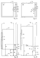
- FIGS. 2A to 2D show - as a second embodiment of the invention - an elevator installation with a buffer 30 in different schematic views and in different states.
- the buffer 30 shown is a buffer for supporting an elevator car 35 above a floor 38 of an elevator shaft 31.
- the buffer serves as overrun protection and as a means of creating a temporary protection zone.
- the elevator car 35 is connected to a counterweight such that the elevator car 35 can be moved up and down along a path V K and the counterweight along a path V G in the elevator shaft 31.
- the counterweight, the suspension element for the elevator car 35 and the counterweight, the traction sheave, the guide rails and the other usual elements of an elevator installation are not shown in FIGS. 2A to 2D.
- the buffer 30 has an elongated extension substantially parallel to the paths V K and V G of the elevator car 35 and the counterweight.
- the buffer 30 is designed and arranged such that it projects at least partially into the path V K of the elevator car and into the path V G of the counterweight.
- the buffer 30 includes a lower, as a strong damper designed base element 32 and a slimmer upper Part 33, which is designed as a weak damper.
- the Buffer 30 includes movable means 34 that are on top Part 33 sit and between different positions can be rotated as in Figures 2B and 2D indicated.
- the movable means 34 are shown in FIG Embodiment executed symmetrically, i.e. they protrude same parts on both sides over the upper part 33 out.
- the buffer 30 is shown in FIGS. 2A and 2B in a so-called normal state.
- the movable means 34 are in their normal position, ie they do not protrude into the paths V K or V G.
- FIGS. 2C and 2D show the buffer 30 in a so-called operating state. In this case, the movable means 34 are in their operating position, ie they protrude into the paths V K or V G.
- the buffer 30 is located at least partially between the web V K of the elevator car 35 and the web V G of the counterweight. 2A and 2C, the projection K3 of the elevator car 35 and the projection G3 of the counterweight, each projected onto the shaft floor, are shown.
- the projections K3 and G3 are shown in dashed lines in the areas in which they overlap with the base 32.1 of the base element 32 on the shaft bottom 38.
- Elevator car 35 When in use, there is mechanical contact Elevator car 35 with the movable means 34 of the buffer 30 as soon as the elevator car 35 has a first predetermined one Distance Z3 with respect to the floor 38 falls below. In the shown embodiment sits with the elevator car 35 a lower edge on the movable means 34, such as shown in Fig. 2D. This can, if necessary, in the area a temporary protection zone at the bottom of the shaft be created.
- the buffer 30 with the movable means 34 is like this designed and arranged that in use also a mechanical contact with the counterweight occurs when that Counterweight the predetermined distance Z3 with respect to the Bottom 38 falls below.
- the counterweight is in the Figures 2A to 2D not visible because it is on the top
- the shaft end is when the elevator car 35 is at lower shaft end.
- FIG. 2B shows the buffer 30 in the normal state. Since the upper part 33 of the buffer 30 is not in the path of the Elevator car protrudes, the elevator car 35 can Approach landing door 37 of the lower floor without one to establish mechanical contact with the buffer 30. In the in Fig. 2B situation can get on or off through the cabin door 36 and the shaft door 37, when the elevator car is at the lowest stopping position on occupies the lowest floor.
- Elevator car 35 If the lowest stopping position is overrun the elevator car 35 downwards (not in FIGS. 2A to 2D), then there is a mechanical contact of the Elevator car 35 with the designed as a strong damper Base element 32 of the buffer 30 as soon as the elevator car 35 a predetermined distance Z3.1 with respect to the floor 38 below. In the embodiment shown, the Elevator car 35 then with a lower edge on the Base element 32. This means that in an "emergency" Elevator car 35 are braked and stopped.
- the buffer 30 is transferred from the normal state to the operating state, this being done by moving the movable means 34 about an axis of rotation which is oriented essentially parallel to the path V K of the elevator car 35 or to the path V G of the counterweight, be rotated.
- the respective position of the movable means is controlled by means of a drive and a control device acting on the drive.
- the drive and the control device are not shown in the figures.
- the elevator car 35 can be moved downwards until it touches the movable means 34. In this way, a protection zone is created below the elevator car 35.
- a shaft door 37 is arranged such that a person can enter and / or leave the protection zone through an opening in the shaft door 37.
- the distance Z3 ensures sufficient distance from the floor 38 to enable safe and problem-free work in the protection zone.
- Elevator system with shaft pit acts and since that Base element 32 has an elongated extent H3 at any time a flat protection zone was created, in which the Elevator car 35 can not penetrate. Even if through an error or the necessary due to incorrect operation A change to the operational state has not taken place Person in the pit should not be crushed as always a minimum distance due to the height H3 of the base element 32 is preserved.
- the base element 32 and / or the upper part 33 have an extension in the direction of the path V K or V G depending on their mechanical load.
- the load dependency of this extension essentially determines the ability of the base element 32 or of the upper part 33 to brake and stop the elevator car or the counterweight when it hits the buffer 30.
- the extent of the buffer 30 in the direction of the path V K is shown reduced by a distance ⁇ Z in comparison to the distance Z3 in FIG. 2D.
- the extent of the buffer 30 in the direction of the path V G is reduced to a height below the distance Z3 if the counterweight loads the buffer 30.
- the buffer 30 can also create a temporary protection zone in the region of the upper shaft end. However, this state is not shown in FIGS. 2A to 2D.
- the movable means 34 are moved into the path V G of the counterweight and the counterweight is supported by the buffer 30 as soon as the counterweight falls below the distance Z3 to the floor 38.
- the elevator car 35 is also held at a fixed predetermined distance from the shaft head. This creates a protection zone at the top of the shaft.
- FIGS 3A to 3D show - as a third Embodiment of the invention - an elevator system with a buffer 40 in various schematic views and in different states. It is the shown buffer 40 around a buffer to support a Elevator car 45 over a floor 48 of an elevator shaft 41.
- the buffer serves as overrun protection and means for Create a temporary protection zone in a pitless one Elevator system, i.e. in an elevator system where the lowest holding level of the elevator car in such a way short distance above the ground that there is no space for a pit.
- the elevator car 45 is so connected to a counterweight that the Elevator car 45 and the counterweight along tracks in the Elevator shaft 41 can be moved up and down.
- the Counterweight, the suspension element for the elevator car 45 and the counterweight, the traction sheave, the guide rails and are the other common elements of an elevator system not shown in Figures 3A to 3D.
- the buffer 40 has an elongated extension substantially parallel to the Paths of the elevator car 45 and the counterweight.
- the Buffer 40 is designed and arranged so that it depends on Condition at least partially in the path of the elevator car and protrudes into the path of the counterweight.
- the buffer 40 includes a lower, as a strong damper designed base element 43 and movable means 44, the sit on the base element 43 and can be rotated, as indicated in Figures 3C and 3D.
- the moveable Means 44 are in the embodiment shown symmetrical, i.e. they protrude in equal parts on both sides beyond the base element 43.
- the Movable means 44 include dampers 44.1, which in Recesses of the movable means 44 sit.
- the buffer 40 is in one in FIGS. 3A and 3B so-called normal state shown.
- the movable means 44 and 44.1 in their Normal position, i.e. they do not protrude into the path of the Elevator car 45 and the counterweight.
- Figures 3C and 3D is the buffer 40 in a so-called Operating condition shown.
- the movable means 44 and 44.1 in their operating position, i.e. they protrude into the path of the elevator car 45 and the Counterweight.
- the buffer 40 is at least partly between the elevator car track and the track of the counterweight. Illustrative is in the figures 3A and 3C the projection K4 of the floor 45.2 of the Elevator car 45 and the projection G4 the bottom of the Counterweight shown.
- Elevator car 45 When in use, there is mechanical contact Elevator car 45 with the damper 44.1 of the buffer 40, as soon as the elevator car 45 a first predetermined distance Z4 falls below with respect to the bottom 48. In the shown embodiment sits the elevator car 45 a lower edge on the damper 44.1, as in Fig. 3D shown.
- the buffer 40 is therefore eccentrically loaded. If necessary, this can be done in the lower area A temporary protection zone will be created at the shaft.
- the buffer 40 with the movable means 44, 44.1 is so designed and arranged that in use also a mechanical contact with the counterweight occurs when that Counterweight the predetermined distance Z4 with respect to the Bottom 48 falls below.
- the counterweight is in the Figures 3A to 3D are not visible because it is at the top Is at the shaft end when the elevator car 45 is at lower shaft end.
- the buffer 40 is shown in the normal state. Since in the normal state the movable means 44, 44.1 of the Buffer 40 not in the path of the bottom 45.2 of the Elevator car 45 protrude, the elevator car 45 can Approach landing door 47 of the lower floor without one establish mechanical contact with the buffer 40. It is noted that in the condition shown Distance D between one at the elevator car 45 attached angle 45.1 (buffer stop) and the movable Means 44.1 exist. In the situation shown in Fig. 3B can an entry or exit through the cabin door 46 and the Landing door 47 take place.
- FIGS. 3A and 3C are each with dashed lines a projection K4.1 of the angle 45.1 and a projection G4.1 of said angle or protruding element on the counterweight, respectively projected onto the shaft floor, shown.
- the buffer 40 is removed from the Normal state converted to the operational state, whereby the happens by moving the movable means 44 into the tracks of the floor 45.2 of the elevator car 45 or the underside the counterweight are rotated (Fig. 3C and 3D).
- the necessary change can be made, for example, by a (Key) switch or triggered electronically become.
- the Elevator car 45 slowly moves down until it is on the Damper 44.1 touches down. A person can enter the protection zone enter through an opening in the landing door 47 and / or leave.
- the distance Z4 ensures sufficient Distance from the ground 48 to a safe and easy To enable work in the protection zone.
- a temporary buffer can also be created using the same buffer 40 Protection zone created in the area of the upper shaft end become. However, this state is not shown in FIGS. 3A shown to 3D.
- the counterweight is prevented from the Distance between Z4 and floor 48 is less.
- the elevator car 45 at a fixed distance from the shaft head held. This creates a protection zone at the top Shaft end.
- the Elevator car and the counterweight are not on the same Supported.
- the embodiments according to FIG. 2A-2D and 3A-3D can be modified accordingly by an appropriate adaptation of the forms of the movable means 34 and 44 and 44.1.
- the buffer can be a Have damping characteristics that are specific to the application is adjusted.
- Damper 44.1 used which is a slightly damped Put on the elevator car 35 or the counterweight allow the movable means 44 when a protection zone to be created.
- the movable means 44 are so spared in operation. If the elevator car and / or that Counterweight at high speed on each Impact buffers - especially when driving over the bottom or top stop position of the elevator car on the other hand - then the damping characteristics come the base elements 12, 32 or 43 are used.
- the buffers according to the invention can be prepared using special agents be equipped with an asymmetrical load allow without the buffer "buckling” or "evading".
- the buffer can be wholly or partially with a surrounded by a corset-like element or by special means be led to due to the eccentric To compensate for bending moments occurring in the buffer load.
- the buffer completely between the elevator car and the counterweight arranged (see for example Fig. 3A).
- the buffer element be arranged entirely or partially under the counterweight and acts directly on the counterweight. A movable one The buffer element then acts as required accordingly to the elevator car.
- the cross section of the buffer can be chosen arbitrarily.
- Buffers 10 and 30 are generally round Cross section parallel to the floor of the elevator shaft.
- buffer 40 has 43 in the lower region, for example a square cross section.
- a movement of the movable Buffer means electro-magnetic, hydraulic, pneumatic, manual, or by means of a servomotor respectively.
- a pit set used that a drive / converter unit, a Speed limiter, an attachment for the Includes guide rails and the buffer. Thereby Installation in the elevator shaft is noticeably easier.
- the present invention is also suitable for use in an elevator system in backpack disposition.
- the invention is particularly for use in Suitable elevator systems that have little or no Have pit and headroom heights.
- the movable means 14, 14.1, 34, 44 and 44.1 can in Modified the scope of the invention in various ways become. They can be replaced by funds that come from a basic position can be folded out, swung out, slidable and / or rotatable and each in Paths of the elevator car and / or the counterweight are movable to the elevator car and / or that Counterweight at a distance above the ground support.
- the movable means can by a suitable Arrangement can also be designed so that the elevator car and the counterweight at different heights can be supported. They can be multi-part or too be designed in one piece.
Landscapes
- Maintenance And Inspection Apparatuses For Elevators (AREA)
Abstract
Description
- Fig. 1A
- eine schematische Draufsicht einer ersten Ausführungsform eines Puffers gemäss Erfindung, in einem Normalzustand;
- Fig. 1B
- eine schematische Seitenansicht der ersten Ausführungsform eines Puffers gemäss Erfindung, in dem Normalzustand;
- Fig. 1C
- eine schematische Draufsicht der ersten Ausführungsform eines Puffers gemäss Erfindung, in einem Einsatzzustand;
- Fig. 1D
- eine schematische Seitenansicht der ersten Ausführungsform eines Puffers gemäss Erfindung, in dem Einsatzzustand, wobei eine temporäre Schutzzone geschaffen ist;
- Fig. 1E
- eine schematische Seitenansicht eines gesamten Aufzugsschachts mit der ersten Ausführungsform eines Puffers gemäss Erfindung, in dem Einsatzzustand, wobei ein Gegengewicht auf dem Puffer aufsitzt und eine Schutzzone am oberen Schachtende geschaffen ist;
- Fig. 1F
- eine schematische Seitenansicht des Aufzugsschachts mit der ersten Ausführungsform eines Puffers gemäss Erfindung, in dem Normalzustand, wobei ein Gegengewicht auf dem Puffer aufsitzt und ein Überfahren einer obersten Halteposition nach oben verhindert ist;
- Fig. 2A
- eine schematische Draufsicht einer zweiten Ausführungsform eines Puffers gemäss Erfindung, in einem Normalzustand;
- Fig. 2B
- eine schematische Seitenansicht der zweiten Ausführungsform eines Puffers gemäss Erfindung, in dem Normalzustand;
- Fig. 2C
- eine schematische Draufsicht der zweiten Ausführungsform eines Puffers gemäss Erfindung, in einem Einsatzzustand;
- Fig. 2D
- eine schematische Seitenansicht der zweiten Ausführungsform eines Puffers gemäss Erfindung, in dem Einsatzzustand, wobei eine temporäre Schutzzone am Schachtboden geschaffen ist;
- Fig. 3A
- eine schematische Draufsicht einer dritten Ausführungsform eines Puffers gemäss Erfindung, in einem Normalzustand;
- Fig. 3B
- eine schematische Seitenansicht der dritten Ausführungsform eines Puffers gemäss Erfindung, in dem Normalzustand, wobei die nach unten über eine unterste Haltposition hinaus fahrende Aufzugskabine gestoppt wird;
- Fig. 3C
- eine schematische Draufsicht der dritten Ausführungsform eines Puffers gemäss Erfindung, in einem Einsatzzustand;
- Fig. 3D
- eine schematische Seitenansicht der dritten Ausführungsform eines Puffers gemäss Erfindung, in dem Einsatzzustand, wobei eine temporäre Schutzzone geschaffen ist.
Claims (15)
- Aufzugsanlage mit einem Puffer (10, 30, 40) zum Schaffen von mindestens einer Schutzzone, wobei die Aufzugsanlage eine Aufzugskabine (15, 35, 45) und ein Gegengewicht (23) für die Aufzugskabine umfasst und die Aufzugskabine (15, 35, 45) und das Gegengewicht (23) längs Bahnen (VK, VG) bewegbar sind,
dadurch gekennzeichnet, dass der Puffer (10, 30, 40) bewegbare Mittel (14, 14.1, 34, 44, 44.1), die in die Bahn (VK) der Aufzugskabine (15, 35, 45) hineinbewegbar sind,
und bewegbare Mittel (14.1, 34, 44, 44.1), die in die Bahn (VG) des Gegengewichts (23) hineinbewegbar sind, umfasst. - Aufzugsanlage nach Anspruch 1, dadurch gekennzeichnet, dass
die bewegbaren Mittel (14, 34, 44, 44.1) in eine Einsatzstellung bringbar sind, in welcher sie derart angeordnet sind, dass
ein mechanischer Kontakt zwischen den bewegbaren Mitteln (14, 34, 44, 44.1) und der Aufzugskabine (15, 35, 45) erfolgt, wenn die Aufzugskabine (15, 35, 45) eine erste vorgegebene Distanz (Z1.1, Z3, Z4) bezüglich eines Bodens (18, 38, 48) unterschreitet, und/oder dass
ein mechanischer Kontakt zwischen den bewegbaren Mitteln (14.1, 34, 44, 44.1) und dem Gegengewicht (23) erfolgt, wenn das Gegengewicht (23) eine zweite vorgegebene Distanz (Z1.2, Z3, Z4) bezüglich eines Bodens (18, 38, 48) unterschreitet. - Aufzugsanlage nach Anspruch 2, dadurch gekennzeichnet, dass die bewegbaren Mittel (14, 14.1, 34, 44, 44.1), ausgehend von der Einsatzstellung, aus der Bahn (VK) der Aufzugskabine (15, 35, 45) und/oder der Bahn (VG) des Gegengewichts (23) herausbewegbar sind.
- Aufzugsanlage nach den Ansprüchen 2 und 3, dadurch gekennzeichnet, dass die bewegbaren Mittel (14, 14.1, 34, 44, 44.1) in eine Normalstellung bringbar sind, in welcher sie derart angeordnet sind,
dass kein mechanischer Kontakt zwischen den bewegbaren Mitteln (14, 34, 44, 44.1) und der Aufzugskabine (45) erfolgt, wenn die Aufzugskabine (15, 35, 45) die erste vorgegebene Distanz (Z1.1, Z3, Z4) bezüglich eines Bodens (18, 38, 48) unterschreitet, und dass
kein mechanischer Kontakt zwischen den bewegbaren Mitteln (14.1, 34, 44, 44.1) und dem Gegengewicht (23) erfolgt, wenn das Gegengewicht (23) die zweite vorgegebene Distanz (Z1.2, Z3, Z4) bezüglich des Bodens (18, 38, 48) unterschreitet. - Aufzugsanlage nach Anspruch 3, dadurch gekennzeichnet, dass die bewegbaren Mittel (14, 34, 44, 44.1) in der Einsatzstellung derart angeordnet sind, dass der mechanische Kontakt zwischen den bewegbaren Mitteln (14, 34, 44, 44.1) und der Aufzugskabine (15, 35, 45) derart realisierbar ist, dass die Aufzugskabine (15, 35, 45) oberhalb des Bodens (18, 38, 48) gestützt ist und eine Schutzzone zwischen dem Boden (18, 38, 48) und der Aufzugskabine (15, 35, 45) besteht.
- Aufzugsanlage) nach Anspruch 3, dadurch gekennzeichnet, dass die bewegbaren Mittel (14.1, 34, 44, 44.1) in der Einsatzstellung derart angeordnet sind, dass der mechanische Kontakt zwischen den bewegbaren Mitteln (14.1, 34, 44, 44.1) und dem Gegengewicht (23) derart realisierbar ist, dass das Gegengewicht (23) oberhalb des Bodens (18, 38, 48) gestützt ist.
- Aufzugsanlage nach Anspruch 6, dadurch gekennzeichnet, dass die Aufzugskabine (15, 35, 45) mit dem Gegengewicht (23) mittels eines Tragmittels (23.1) von einer derartigen Länge verbunden ist und das Gegengewicht (23) in einer derartigen Höhe über dem Boden stützbar ist, dass eine Schutzzone oberhalb der Aufzugskabine (15, 35, 45) besteht, wobei sich diese Schutzzone vorzugsweise zwischen einem oberen Bereich der Aufzugskabine (15, 35, 45) und einem oberen Ende eines Aufzugschachtes (11, 31, 41) befindet.
- Aufzugsanlage nach einem der Ansprüche 1 bis 7,
dadurch gekennzeichnet, dass der Puffer (10, 30, 40) eine geeignete Dämpfungscharakteristik aufweist, um bei einem Erfolgen eines mechanischen Kontakts mit der Aufzugskabine (15, 35, 45) oder mit dem Gegengewicht (23) ein weiches Aufsetzen zu ermöglichen
und/oder
dass sich mindestens ein oberer Teil (13, 33, 43) des Puffers (10, 30, 40) zwischen einer Flächenprojektion (K1, K3, K4) der Aufzugskabine (15, 35, 45) und einer Flächenprojektion (G1, G3, G4) des Gegengewichts (23) befindet
und/oder dass es sich bei den bewegbaren Mitteln (14, 14.1, 34, 44, 44.1) um ausklappbare Mittel,
schwenkbare Mittel, schiebbare Mittel oder drehbare Mittel handelt. - Aufzugsanlage nach Anspruch 4, dadurch gekennzeichnet, dass ein pufferndes Element (12, 32, 43) derart angeordnet ist, dass es in die Bahn (VK) der Aufzugskabine (15, 35, 45) ragt, wenn die bewegbaren Mittel (14, 14.1, 34, 44, 44.1) in die Normalstellung gebracht sind, und dass das puffernde Element (12, 32, 43) derart ausgebildet ist, dass die Aufzugskabine (15, 35, 45) mit dem puffernden Element (12, 32, 43) in einen mechanischen Kontakt bringbar und auf einer dritten Distanz über dem Boden (18, 38, 48) stützbar ist, welche geringer ist als die erste vorgegebene Distanz (Z1.1, Z3, Z4).
- Aufzugsanlage nach Anspruch 4, dadurch gekennzeichnet, dass ein pufferndes Element (12, 32, 43) derart angeordnet ist, dass es in die Bahn (VG) des Gegengewichts (23) ragt, wenn die bewegbaren Mittel (14, 14.1, 34, 44, 44.1) in die Normalstellung gebracht sind, und dass das puffernde Element (12, 32, 43) derart ausgebildet ist, dass das Gegengewicht (23) mit dem puffernden Element (12, 32, 43) in einen mechanischen Kontakt bringbar und auf einer vierten Distanz über dem Boden stützbar ist, welche geringer ist als die zweite vorgegebene Distanz (Z1.2, Z3, Z4).
- Aufzugsanlage nach Anspruch 9, dadurch gekennzeichnet, dass der Puffer (10, 30, 40) als Überfahrschutz dient, der durch den mechanischen Kontakt mit der Aufzugskabine (15, 35, 45) die Aufzugskabine (15, 35, 45) beim Überfahren einer untersten Halteposition in Abwärtsrichtung abbremst und stoppt.
- Aufzugsanlage nach Anspruch 10, dadurch gekennzeichnet, dass er als Überfahrschutz dient, der durch den mechanischen Kontakt mit dem Gegengewicht (23) das Gegengewicht (23) in Abwärtsrichtung abbremst und stoppt und damit die Aufzugskabine (15, 35, 45) beim Überfahren einer obersten Halteposition in Aufwärtsrichtung abbremst und stoppt.
- Die Aufzugsanlage gemäss Anspruch 1-12, dadurch gekennzeichnet, dass die Aufzugskabine (45), das Gegengewicht (23) und der Puffer (40) in einem grubenlosen Aufzugsschacht (41) angeordnet sind.
- Verfahren zum Schaffen einer Schutzzone in einer Aufzugsanlage mit einem Puffer (10, 30, 40), der bewegbare Mittel (14, 14.1, 34, 44, 44.1) aufweist, und mit einer Aufzugskabine (15, 35, 45), die so mit einem Gegengewicht (23) verbunden ist, dass die Aufzugskabine (15, 35, 45) und das Gegengewicht (23) längs Bahnen (VK, VG) bewegbar sind, wobei das Verfahren die folgenden Schritte umfasst:Bewegen der bewegbaren Mittel (14, 34, 44, 44.1) in die Bahn (VK) der Aufzugskabine (15, 35, 45) falls, es einen Bedarf für eine Schutzzone unterhalb der Aufzugskabine (15, 35, 45) gibt, wobei die Schutzzone durch einen mechanischen Kontakt der bewegbaren Mittel (14, 34, 44, 44.1) mit der Aufzugskabine (15, 35, 45) geschaffen wird, der die Einhaltung einer ersten vorgegebenen Distanz zwischen der Aufzugskabine (15, 35, 45) und einem Boden (18, 38, 48) gewährleistet,Bewegen der bewegbaren Mittel (14.1, 34, 44, 44.1) in die Bahn (VG) des Gegengewichts (23), falls es einen Bedarf für eine Schutzzone oberhalb der Aufzugskabine (15, 35, 45) gibt, wobei die Schutzzone durch einen mechanischen Kontakt der bewegbaren Mittel (14.1, 34, 44, 44.1) mit dem Gegengewicht (23) geschaffen wird, der die Einhaltung einer zweiten vorgegebenen Distanz zwischen dem Gegengewicht (23) und dem Boden (18, 38, 38) gewährleistet.
- Das Verfahren nach Anspruch 14, dadurch gekennzeichnet, dass es den folgenden Schritt umfasst: Herausbewegen der bewegbaren Mittel (14, 14.1, 34, 44, 44.1) aus der Bahn (VK, VG), falls es keinen Bedarf für eine Schutzzone gibt.
Priority Applications (1)
| Application Number | Priority Date | Filing Date | Title |
|---|---|---|---|
| EP04011503A EP1479636A1 (de) | 2003-05-21 | 2004-05-14 | Puffer zum Schaffen einer Schutzzone in einer Aufzugsanlage |
Applications Claiming Priority (3)
| Application Number | Priority Date | Filing Date | Title |
|---|---|---|---|
| EP03405352 | 2003-05-21 | ||
| EP03405352 | 2003-05-21 | ||
| EP04011503A EP1479636A1 (de) | 2003-05-21 | 2004-05-14 | Puffer zum Schaffen einer Schutzzone in einer Aufzugsanlage |
Publications (1)
| Publication Number | Publication Date |
|---|---|
| EP1479636A1 true EP1479636A1 (de) | 2004-11-24 |
Family
ID=33099719
Family Applications (1)
| Application Number | Title | Priority Date | Filing Date |
|---|---|---|---|
| EP04011503A Withdrawn EP1479636A1 (de) | 2003-05-21 | 2004-05-14 | Puffer zum Schaffen einer Schutzzone in einer Aufzugsanlage |
Country Status (1)
| Country | Link |
|---|---|
| EP (1) | EP1479636A1 (de) |
Cited By (7)
| Publication number | Priority date | Publication date | Assignee | Title |
|---|---|---|---|---|
| EP1674416A1 (de) * | 2004-12-23 | 2006-06-28 | ThyssenKrupp Aufzugswerke GmbH | Aufzug und Fahrkorb |
| WO2008002300A1 (en) * | 2006-06-26 | 2008-01-03 | Otis Elevator Company | Retractable stop for maintaining overhead clearance above an elevator car |
| EP1908720A1 (de) | 2006-10-06 | 2008-04-09 | Inventio Ag | Sperre für eine Aufzugsschachtgrube |
| US8807289B2 (en) | 2006-10-06 | 2014-08-19 | Inventio Ag | Elevator pit barrier |
| DE102017004719A1 (de) * | 2017-05-16 | 2018-11-22 | Michael Geisenhofer | Vorrichtung für einen gesicherten Bereich in einem Aufzugschacht |
| CN110510542A (zh) * | 2019-09-29 | 2019-11-29 | 山东富士制御电梯有限公司 | 一种导轨式升降平台防坠落装置 |
| CN111295351A (zh) * | 2017-10-31 | 2020-06-16 | 因温特奥股份公司 | 用于在电梯竖井中执行维护工作的装置 |
Citations (4)
| Publication number | Priority date | Publication date | Assignee | Title |
|---|---|---|---|---|
| JPH05201647A (ja) * | 1992-01-28 | 1993-08-10 | Mitsubishi Electric Corp | エレベータ装置 |
| EP0725033A1 (de) * | 1995-01-31 | 1996-08-07 | Inventio Ag | Temporäre Arbeitsraumsicherung |
| JPH09227046A (ja) * | 1996-02-26 | 1997-09-02 | Mitsubishi Denki Bill Techno Service Kk | エレベータ装置のかごストッパ装置 |
| EP1052212A1 (de) * | 1999-05-14 | 2000-11-15 | Inventio Ag | Einrichtung zur Ausführung von Arbeiten in einem Aufzugsschacht |
-
2004
- 2004-05-14 EP EP04011503A patent/EP1479636A1/de not_active Withdrawn
Patent Citations (4)
| Publication number | Priority date | Publication date | Assignee | Title |
|---|---|---|---|---|
| JPH05201647A (ja) * | 1992-01-28 | 1993-08-10 | Mitsubishi Electric Corp | エレベータ装置 |
| EP0725033A1 (de) * | 1995-01-31 | 1996-08-07 | Inventio Ag | Temporäre Arbeitsraumsicherung |
| JPH09227046A (ja) * | 1996-02-26 | 1997-09-02 | Mitsubishi Denki Bill Techno Service Kk | エレベータ装置のかごストッパ装置 |
| EP1052212A1 (de) * | 1999-05-14 | 2000-11-15 | Inventio Ag | Einrichtung zur Ausführung von Arbeiten in einem Aufzugsschacht |
Non-Patent Citations (2)
| Title |
|---|
| PATENT ABSTRACTS OF JAPAN vol. 017, no. 641 (M - 1516) 29 November 1993 (1993-11-29) * |
| PATENT ABSTRACTS OF JAPAN vol. 1998, no. 01 30 January 1998 (1998-01-30) * |
Cited By (8)
| Publication number | Priority date | Publication date | Assignee | Title |
|---|---|---|---|---|
| EP1674416A1 (de) * | 2004-12-23 | 2006-06-28 | ThyssenKrupp Aufzugswerke GmbH | Aufzug und Fahrkorb |
| WO2008002300A1 (en) * | 2006-06-26 | 2008-01-03 | Otis Elevator Company | Retractable stop for maintaining overhead clearance above an elevator car |
| US8028808B2 (en) | 2006-06-26 | 2011-10-04 | Otis Elevator Company | Retractable stop for maintaining overhead clearance above an elevator car |
| EP1908720A1 (de) | 2006-10-06 | 2008-04-09 | Inventio Ag | Sperre für eine Aufzugsschachtgrube |
| US8807289B2 (en) | 2006-10-06 | 2014-08-19 | Inventio Ag | Elevator pit barrier |
| DE102017004719A1 (de) * | 2017-05-16 | 2018-11-22 | Michael Geisenhofer | Vorrichtung für einen gesicherten Bereich in einem Aufzugschacht |
| CN111295351A (zh) * | 2017-10-31 | 2020-06-16 | 因温特奥股份公司 | 用于在电梯竖井中执行维护工作的装置 |
| CN110510542A (zh) * | 2019-09-29 | 2019-11-29 | 山东富士制御电梯有限公司 | 一种导轨式升降平台防坠落装置 |
Similar Documents
| Publication | Publication Date | Title |
|---|---|---|
| EP2219985B1 (de) | Aufzugssystem mit vertikal und horizontal verfahrbaren aufzugkabinen | |
| EP2398729B1 (de) | Aufzugsanlage mit einem mehrdeckfahrzeug | |
| DE69203697T2 (de) | Doppelseitige Fangvorrichtung. | |
| EP2585395B1 (de) | Aufzuganlage | |
| DE69000686T2 (de) | Wagenparkanlage fuer individuelles und automatisches parken im stadtbereich. | |
| WO2009077397A1 (de) | Auffahrbremse für zwei unabhängig voneinander verfahrende aufzugkörper | |
| EP3310699A1 (de) | Sicherheitseinrichtung einer aufzugsanlage | |
| EP1999043B1 (de) | Werkstückträgersystem | |
| EP2346771A1 (de) | Modernisierungsverfahren für aufzuganlagen | |
| EP2512969A1 (de) | Aufzuganlage mit doppeldecker | |
| DE102016007070A1 (de) | Fangvorrichtung für Hubeinrichtung | |
| EP1479636A1 (de) | Puffer zum Schaffen einer Schutzzone in einer Aufzugsanlage | |
| DE112015005891T5 (de) | Aufzugsvorrichtung | |
| DE102017004719A1 (de) | Vorrichtung für einen gesicherten Bereich in einem Aufzugschacht | |
| EP1693331A1 (de) | Aufzugssystem mit mehreren Schächten und mit Aufzugskabinen welche vom gewählten Antriebssystem an- und abgekuppelt werden können | |
| DE19752232C2 (de) | Seilaufzug mit in den Aufzugschacht hineinragenden Betonsockel | |
| EP1479637B1 (de) | Puffer und aufzugsanlage mit einem solchen puffer | |
| EP3924285B1 (de) | Aufzugsystem | |
| EP3931141B1 (de) | Aufzugssystem | |
| EP2468674A1 (de) | Aufzuganlage mit Doppeldecker | |
| WO2011107390A1 (de) | Verfahren zum energiesparenden betrieb einer aufzugsanlage und entsprechende aufzugsanlage | |
| EP2050706B1 (de) | Festhaltevorrichtung | |
| EP3645443B1 (de) | Aufzugsanlage | |
| EP4563512B1 (de) | Fahrkorb, fahrkorbanordnung sowie aufzugsanlage mit zwei fahrkörben in einem aufzugsschacht | |
| EP4313833B1 (de) | Fahrkorbanordnung für einen doppelstockaufzug und doppelstockaufzug |
Legal Events
| Date | Code | Title | Description |
|---|---|---|---|
| PUAI | Public reference made under article 153(3) epc to a published international application that has entered the european phase |
Free format text: ORIGINAL CODE: 0009012 |
|
| AK | Designated contracting states |
Kind code of ref document: A1 Designated state(s): AT BE BG CH CY CZ DE DK EE ES FI FR GB GR HU IE IT LI LU MC NL PL PT RO SE SI SK TR |
|
| AX | Request for extension of the european patent |
Extension state: AL HR LT LV MK |
|
| 17P | Request for examination filed |
Effective date: 20050509 |
|
| REG | Reference to a national code |
Ref country code: HK Ref legal event code: DE Ref document number: 1071122 Country of ref document: HK |
|
| AKX | Designation fees paid |
Designated state(s): AT BE BG CH CY CZ DE DK EE ES FI FR GB GR HU IE IT LI LU MC NL PL PT RO SE SI SK TR |
|
| 17Q | First examination report despatched |
Effective date: 20070724 |
|
| R17C | First examination report despatched (corrected) |
Effective date: 20080724 |
|
| REG | Reference to a national code |
Ref country code: HK Ref legal event code: WD Ref document number: 1071122 Country of ref document: HK |
|
| STAA | Information on the status of an ep patent application or granted ep patent |
Free format text: STATUS: THE APPLICATION HAS BEEN WITHDRAWN |
|
| 18W | Application withdrawn |
Effective date: 20170406 |