EP1479552B1 - Andrückvorrichtung für Abdichtungsprofile bei Kraftfahrzeugkarosserien - Google Patents
Andrückvorrichtung für Abdichtungsprofile bei Kraftfahrzeugkarosserien Download PDFInfo
- Publication number
- EP1479552B1 EP1479552B1 EP04011344A EP04011344A EP1479552B1 EP 1479552 B1 EP1479552 B1 EP 1479552B1 EP 04011344 A EP04011344 A EP 04011344A EP 04011344 A EP04011344 A EP 04011344A EP 1479552 B1 EP1479552 B1 EP 1479552B1
- Authority
- EP
- European Patent Office
- Prior art keywords
- drive shaft
- press
- secondary shaft
- shaft housing
- piston
- Prior art date
- Legal status (The legal status is an assumption and is not a legal conclusion. Google has not performed a legal analysis and makes no representation as to the accuracy of the status listed.)
- Expired - Lifetime
Links
- 238000007789 sealing Methods 0.000 claims description 21
- 239000002184 metal Substances 0.000 claims description 13
- 238000000465 moulding Methods 0.000 claims 3
- 238000006073 displacement reaction Methods 0.000 description 3
- 238000011161 development Methods 0.000 description 2
- 230000018109 developmental process Effects 0.000 description 2
- 238000000034 method Methods 0.000 description 2
- VREFGVBLTWBCJP-UHFFFAOYSA-N alprazolam Chemical compound C12=CC(Cl)=CC=C2N2C(C)=NN=C2CN=C1C1=CC=CC=C1 VREFGVBLTWBCJP-UHFFFAOYSA-N 0.000 description 1
- 230000015572 biosynthetic process Effects 0.000 description 1
- 238000004891 communication Methods 0.000 description 1
- 230000008878 coupling Effects 0.000 description 1
- 238000010168 coupling process Methods 0.000 description 1
- 238000005859 coupling reaction Methods 0.000 description 1
- 230000001419 dependent effect Effects 0.000 description 1
- 238000007689 inspection Methods 0.000 description 1
- 230000014759 maintenance of location Effects 0.000 description 1
- 238000000275 quality assurance Methods 0.000 description 1
- 239000000565 sealant Substances 0.000 description 1
- XLYOFNOQVPJJNP-UHFFFAOYSA-N water Substances O XLYOFNOQVPJJNP-UHFFFAOYSA-N 0.000 description 1
Images

Classifications
-
- B—PERFORMING OPERATIONS; TRANSPORTING
- B23—MACHINE TOOLS; METAL-WORKING NOT OTHERWISE PROVIDED FOR
- B23P—METAL-WORKING NOT OTHERWISE PROVIDED FOR; COMBINED OPERATIONS; UNIVERSAL MACHINE TOOLS
- B23P19/00—Machines for simply fitting together or separating metal parts or objects, or metal and non-metal parts, whether or not involving some deformation; Tools or devices therefor so far as not provided for in other classes
- B23P19/04—Machines for simply fitting together or separating metal parts or objects, or metal and non-metal parts, whether or not involving some deformation; Tools or devices therefor so far as not provided for in other classes for assembling or disassembling parts
- B23P19/047—Machines for simply fitting together or separating metal parts or objects, or metal and non-metal parts, whether or not involving some deformation; Tools or devices therefor so far as not provided for in other classes for assembling or disassembling parts for flexible profiles, e.g. sealing or decorating strips in grooves or on other profiles by devices moving along the flexible profile
-
- B—PERFORMING OPERATIONS; TRANSPORTING
- B60—VEHICLES IN GENERAL
- B60J—WINDOWS, WINDSCREENS, NON-FIXED ROOFS, DOORS, OR SIMILAR DEVICES FOR VEHICLES; REMOVABLE EXTERNAL PROTECTIVE COVERINGS SPECIALLY ADAPTED FOR VEHICLES
- B60J10/00—Sealing arrangements
- B60J10/45—Assembling sealing arrangements with vehicle parts
Definitions
- the invention relates to a pressing device for applying sealing profiles to sheet metal parts of motor vehicle bodies (see, for example, GB-2 327 698-A). Sealing profiles are often attached to sheet metal parts that need to be opened or closed during operation. For example, this is the case with door frames, so that during operation of a motor vehicle no water penetrates through the door gap into the interior of the motor vehicle.
- Such pressing devices have a frequently pneumatically driven drive shaft to which a pressure roller is attached.
- a forming roller is provided, which is arranged on a secondary shaft.
- a sealing profile which has a sheet edge in the interior, it is first placed on a vehicle body edge, along the circumference of the opening. Thereafter, the pressing device is placed on the sealing profile.
- the pinch roller and the forming roller begin to rotate and the sheet edge inside the sealing profile becomes so deformed, that results in a firm frictional connection between the sealing profile and the sheet metal part.
- the invention is based on the task of providing a method and a device for applying sealants to sheet metal parts of motor vehicle bodies, with which a high reliability is achieved, so that the quality assurance can be made less expensive.
- the drive shaft and the secondary shaft are arranged pivotable relative to each other about a pivot axis.
- a reliable attachment of sealing profiles can be achieved.
- the pressure roller is pivoted away from the forming roller and the pressure device is placed on the sealing profile.
- damage to the sealing profile when placing the pressing device according to the invention are avoided.
- the pivoting can take place about a direction perpendicular to the axes of rotation of the drive shaft and the secondary shaft.
- the pivoting can also take place around another pivot axis.
- a pneumatic pressing device which presses the pressure roller and the forming roller in the direction of each other.
- the drive shaft rotates the secondary shaft, in particular via a gear stage, via which the drive shaft and the secondary shaft are engaged with each other.
- This gear stage may have a drive gear on the drive shaft and a secondary gear on the secondary shaft, wherein the pivot axis preferably extends through a region in which the pitch circle of the drive gear and the pitch circle of the secondary gear. If then the toothing is adapted to a pivoting of the drive gear and secondary gear to each other, then there is a particularly good and trouble-free operation.
- the application of pneumatic pressure can be accomplished particularly easily if the pneumatic pressure device has a displaceably arranged piston in the drive shaft housing or in the SekundärwellengehAuse, the front of the piston the respective other housing, so applied to the secondary shaft housing or the drive shaft housing.
- the compressed air supply to the piston can be in communication with the compressed air supply for driving the drive shaft, wherein a manually operable valve for interrupting the supply of compressed air to the piston is advantageously provided. Then, a return spring can push away the pressure roller and the forming roller in the direction of each other, and this can be done particularly easily when the actuatable valve has a vent for the compressed air supply to the piston.
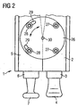
- Figures 1 to 3 show a pressing device 1 according to the invention in various representations and views.
- the pressing device 1 is divided into a drive shaft housing 2, in which a drive shaft 3 is received with a pressure roller 4, and in a secondary shaft housing 5, in which a secondary shaft 6 is received with a forming roller 7.
- the drive shaft 3 is mounted in drive shaft bearings 8 and the secondary shaft 6 is mounted in secondary shaft bearings 9.
- the drive shaft 3 has at its upper end in Figure 1 a drive square 10 for engagement with a pneumatic motor, not shown in this view.
- a drive gear 12 is provided via a splined connection 11.
- the drive gear 12 is engaged with a secondary gear 13 which is fixed via a further spline 14 on the secondary shaft 6. Upon rotation of the drive shaft 3, the secondary shaft 6 rotates to the same extent.
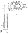
- a pressure piston housing 16 is äufdite, which has a through hole 17 and on the top side a receiving flange 18 which matches its dimensions with the receiving flange 15.
- the pressure piston housing has a pressure cylinder bore 19, in which a pressure piston 20 is received in a longitudinally displaceable manner.
- the pressure piston 20 is actuated via a pressure valve arrangement 21 arranged on the right-hand side of the pressure piston housing 16 in FIG. In this case, the pressure valve assembly 21 on a manual operation button 22 and a vent line 23.
- a compressed air connection 24 is provided on the top side. .
- an actuating lever 25 extends up into the region of the Drukkolbens 20.
- a joint disc 26 is mounted on both sides of the drive shaft housing 2 and the secondary shaft housing 5.
- the flexible disk 26 is fastened with two retaining screws 27 on the drive shaft housing 2.
- two sliding screws 28 are screwed.
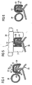
- FIG. 3 shows the pressing device 1 with inserted pneumatic motor 31.
- the pneumatic motor 31 has an actuating lever 32, which determines the supply of compressed air through a central compressed air connection 33.
- two transverse rollers 34 are mounted on the bottom side of the drive shaft housing 2 and on the secondary shaft housing 5, of which the better representation, only one transverse roller 34 is located.
- a spreading spring not shown in this view is provided which presses the drive shaft housing 2 and the secondary shaft housing 5 apart.
- FIG. 4 shows a section of a body 35 on which a sheet metal edge 36 is formed.
- a sealing profile 37 is placed, which is divided into a sealing tube 38, in a holding portion 39 with a U-shaped cross-section and inner gripping lips 40. Inside the holding area 39, a sheet-metal strip 41 with a U-shaped cross-section is poured.
- the presentation is very schematic.
- the sealing profile of the pressing device 1 is compressed, so that the metal strip 41 is deformed.
- the gripping lips 40 engage firmly with the sheet edge 36, whereby a reliable and good connection is achieved.
- the pressing device 1 according to the invention avoids damage to the sealing tube 38, which later results in a good tightness.
Landscapes
- Engineering & Computer Science (AREA)
- Mechanical Engineering (AREA)
- Automatic Assembly (AREA)
- Actuator (AREA)
Priority Applications (1)
| Application Number | Priority Date | Filing Date | Title |
|---|---|---|---|
| PL04011344T PL1479552T3 (pl) | 2003-05-21 | 2004-05-13 | Przyrząd dociskający kształtowe uszczelki, zwłaszcza do blach nadwozi samochodowych |
Applications Claiming Priority (2)
| Application Number | Priority Date | Filing Date | Title |
|---|---|---|---|
| DE10322874A DE10322874A1 (de) | 2003-05-21 | 2003-05-21 | Andrückvorrichtung für Abdichtungsprofile bei Kraftfahrzeugkarosserien |
| DE10322874 | 2003-05-21 |
Publications (2)
| Publication Number | Publication Date |
|---|---|
| EP1479552A1 EP1479552A1 (de) | 2004-11-24 |
| EP1479552B1 true EP1479552B1 (de) | 2006-07-19 |
Family
ID=33039237
Family Applications (1)
| Application Number | Title | Priority Date | Filing Date |
|---|---|---|---|
| EP04011344A Expired - Lifetime EP1479552B1 (de) | 2003-05-21 | 2004-05-13 | Andrückvorrichtung für Abdichtungsprofile bei Kraftfahrzeugkarosserien |
Country Status (4)
| Country | Link |
|---|---|
| EP (1) | EP1479552B1 (pl) |
| DE (2) | DE10322874A1 (pl) |
| ES (1) | ES2270220T3 (pl) |
| PL (1) | PL1479552T3 (pl) |
Families Citing this family (2)
| Publication number | Priority date | Publication date | Assignee | Title |
|---|---|---|---|---|
| CN111497260B (zh) * | 2020-05-18 | 2022-03-29 | 华晨宝马汽车有限公司 | 一种密封条施加装置和系统 |
| CN114654749A (zh) * | 2022-03-21 | 2022-06-24 | 安徽江淮汽车集团股份有限公司 | 一种辅助装配汽车门框胶条的滚压装置 |
Family Cites Families (3)
| Publication number | Priority date | Publication date | Assignee | Title |
|---|---|---|---|---|
| GB2324327B (en) * | 1997-04-18 | 2001-06-13 | Standard Prod Ltd | Clinching tool with rotatable spindles driven by a worm and gear |
| GB2327698B (en) * | 1997-07-25 | 2001-08-01 | Draftex Ind Ltd | Strip fitting tools and methods |
| GB9820965D0 (en) * | 1998-09-25 | 1998-11-18 | Draftex Ind Ltd | Strip fitting tools and methods |
-
2003
- 2003-05-21 DE DE10322874A patent/DE10322874A1/de not_active Withdrawn
-
2004
- 2004-05-13 PL PL04011344T patent/PL1479552T3/pl unknown
- 2004-05-13 EP EP04011344A patent/EP1479552B1/de not_active Expired - Lifetime
- 2004-05-13 ES ES04011344T patent/ES2270220T3/es not_active Expired - Lifetime
- 2004-05-13 DE DE502004000973T patent/DE502004000973D1/de not_active Expired - Lifetime
Also Published As
| Publication number | Publication date |
|---|---|
| PL1479552T3 (pl) | 2006-09-29 |
| ES2270220T3 (es) | 2007-04-01 |
| EP1479552A1 (de) | 2004-11-24 |
| DE502004000973D1 (de) | 2006-08-31 |
| DE10322874A1 (de) | 2004-12-30 |
Similar Documents
| Publication | Publication Date | Title |
|---|---|---|
| DE3153293C2 (de) | Selbsttätig andrückende Abdichtanordnung für die Fensterscheibe eines vertikal verschiebbaren Fahrzeugfensters | |
| DE2806117C2 (de) | Elektrisch betätigbarer Fensterantrieb, insbesondere für Kraftfahrzeuge | |
| DE102010021431B4 (de) | Vorrichtung, um eine Flanschabdeckung mit einem Flansch in Eingriff zu bringen | |
| DE69011473T2 (de) | Gummidichtungen und Verfahren zu ihrer Herstellung. | |
| DE3922866A1 (de) | Dichtstreifen | |
| WO1999048714A1 (de) | Dichtungsprofil für kraftfahrzeuge | |
| WO2007113042A1 (de) | Aufblasbare dichtvorrichtung für ein formwerkzeug | |
| EP2232108B1 (de) | Verschlusseinrichtung zum dichten verschliessen eines füll- und entleerungssystems von eisenbahnkesselwagen oder transporttanks | |
| EP1126938A1 (de) | Bördel- und/oder falzschliessmaschine sowie betriebsverfahren | |
| DE2638684C3 (de) | Betätigungsvorrichtung für den Verschlußdeckel eines Kraftfahrzeugschiebedaches | |
| DE69103389T2 (de) | Dichtungsvorrichtung. | |
| EP1193098A2 (de) | Dichtungssystem für einen Stützhebel an einem öffnungsfähigen Fahrzeugdach | |
| EP1479552B1 (de) | Andrückvorrichtung für Abdichtungsprofile bei Kraftfahrzeugkarosserien | |
| DE102005059201B4 (de) | Pumpenverbindung | |
| DE1963309A1 (de) | Vorrichtung an Schiebetueren | |
| DE4409935A1 (de) | Schienengebundenes Fahrzeug | |
| DE69710563T2 (de) | Vorrichtung zum Befestigen von Dichtungslippen | |
| DE10227138A1 (de) | Abdeckung für ein Kugelgelenk | |
| DE69201030T2 (de) | Membranförderpumpe mit gelenktem Antriebshebel. | |
| DE4327067A1 (de) | Montagevorrichtung für ein auf einen Flansch aufzusteckendes Dichtungsprofil | |
| DE2605588B2 (de) | Verschlußvorrichtung für die Mündung des Schlüsselkanals eines Zylinderschlosses, insbesondere für Kraftfahrzeuge | |
| DE20308337U1 (de) | Vorrichtung zum Auftragen von Fluid | |
| EP1955884B1 (de) | Vorrichtung zur Befestigung eines Dichtungsstrangs an einer Fahrzeugkarosserie | |
| EP0443455B2 (de) | Schwenkvorrichtung für ein Schleuderkettenaggregat | |
| DE10301584A1 (de) | Vorrichtung zur verschieblichen Anordnung eines Paneels |
Legal Events
| Date | Code | Title | Description |
|---|---|---|---|
| PUAI | Public reference made under article 153(3) epc to a published international application that has entered the european phase |
Free format text: ORIGINAL CODE: 0009012 |
|
| AK | Designated contracting states |
Kind code of ref document: A1 Designated state(s): AT BE BG CH CY CZ DE DK EE ES FI FR GB GR HU IE IT LI LU MC NL PL PT RO SE SI SK TR |
|
| AX | Request for extension of the european patent |
Extension state: AL HR LT LV MK |
|
| 17P | Request for examination filed |
Effective date: 20050523 |
|
| AKX | Designation fees paid |
Designated state(s): AT BE BG CH CY CZ DE DK EE ES FI FR GB GR HU IE IT LI LU MC NL PL PT RO SE SI SK TR |
|
| GRAP | Despatch of communication of intention to grant a patent |
Free format text: ORIGINAL CODE: EPIDOSNIGR1 |
|
| GRAS | Grant fee paid |
Free format text: ORIGINAL CODE: EPIDOSNIGR3 |
|
| GRAA | (expected) grant |
Free format text: ORIGINAL CODE: 0009210 |
|
| AK | Designated contracting states |
Kind code of ref document: B1 Designated state(s): CZ DE ES FR GB PL SK |
|
| REG | Reference to a national code |
Ref country code: GB Ref legal event code: FG4D Free format text: NOT ENGLISH |
|
| REF | Corresponds to: |
Ref document number: 502004000973 Country of ref document: DE Date of ref document: 20060831 Kind code of ref document: P |
|
| GBT | Gb: translation of ep patent filed (gb section 77(6)(a)/1977) |
Effective date: 20060824 |
|
| ET | Fr: translation filed | ||
| REG | Reference to a national code |
Ref country code: ES Ref legal event code: FG2A Ref document number: 2270220 Country of ref document: ES Kind code of ref document: T3 |
|
| PLBE | No opposition filed within time limit |
Free format text: ORIGINAL CODE: 0009261 |
|
| STAA | Information on the status of an ep patent application or granted ep patent |
Free format text: STATUS: NO OPPOSITION FILED WITHIN TIME LIMIT |
|
| 26N | No opposition filed |
Effective date: 20070420 |
|
| REG | Reference to a national code |
Ref country code: GB Ref legal event code: 732E Free format text: REGISTERED BETWEEN 20090219 AND 20090225 |
|
| REG | Reference to a national code |
Ref country code: GB Ref legal event code: 732E Free format text: REGISTERED BETWEEN 20090305 AND 20090311 |
|
| REG | Reference to a national code |
Ref country code: GB Ref legal event code: 732E Free format text: REGISTERED BETWEEN 20091029 AND 20091104 |
|
| REG | Reference to a national code |
Ref country code: GB Ref legal event code: 732E Free format text: REGISTERED BETWEEN 20091105 AND 20091111 |
|
| REG | Reference to a national code |
Ref country code: DE Ref legal event code: R081 Ref document number: 502004000973 Country of ref document: DE Owner name: GM GLOBAL TECHNOLOGY OPERATIONS LLC (N. D. GES, US Free format text: FORMER OWNER: GM GLOBAL TECHNOLOGY OPERATIONS, INC., DETROIT, MICH., US Effective date: 20110323 Ref country code: DE Ref legal event code: R081 Ref document number: 502004000973 Country of ref document: DE Owner name: GM GLOBAL TECHNOLOGY OPERATIONS LLC (N. D. GES, US Free format text: FORMER OWNER: GM GLOBAL TECHNOLOGY OPERATIONS, INC., DETROIT, US Effective date: 20110323 |
|
| REG | Reference to a national code |
Ref country code: FR Ref legal event code: PLFP Year of fee payment: 13 |
|
| PGFP | Annual fee paid to national office [announced via postgrant information from national office to epo] |
Ref country code: CZ Payment date: 20160505 Year of fee payment: 13 Ref country code: GB Payment date: 20160511 Year of fee payment: 13 Ref country code: DE Payment date: 20160510 Year of fee payment: 13 Ref country code: ES Payment date: 20160414 Year of fee payment: 13 |
|
| PGFP | Annual fee paid to national office [announced via postgrant information from national office to epo] |
Ref country code: PL Payment date: 20160404 Year of fee payment: 13 Ref country code: FR Payment date: 20160412 Year of fee payment: 13 Ref country code: SK Payment date: 20160405 Year of fee payment: 13 |
|
| REG | Reference to a national code |
Ref country code: DE Ref legal event code: R119 Ref document number: 502004000973 Country of ref document: DE |
|
| GBPC | Gb: european patent ceased through non-payment of renewal fee |
Effective date: 20170513 |
|
| PG25 | Lapsed in a contracting state [announced via postgrant information from national office to epo] |
Ref country code: CZ Free format text: LAPSE BECAUSE OF NON-PAYMENT OF DUE FEES Effective date: 20170513 Ref country code: SK Free format text: LAPSE BECAUSE OF NON-PAYMENT OF DUE FEES Effective date: 20170513 |
|
| REG | Reference to a national code |
Ref country code: SK Ref legal event code: MM4A Ref document number: E 1068 Country of ref document: SK Effective date: 20170513 |
|
| REG | Reference to a national code |
Ref country code: FR Ref legal event code: ST Effective date: 20180131 |
|
| PG25 | Lapsed in a contracting state [announced via postgrant information from national office to epo] |
Ref country code: DE Free format text: LAPSE BECAUSE OF NON-PAYMENT OF DUE FEES Effective date: 20171201 Ref country code: GB Free format text: LAPSE BECAUSE OF NON-PAYMENT OF DUE FEES Effective date: 20170513 |
|
| PG25 | Lapsed in a contracting state [announced via postgrant information from national office to epo] |
Ref country code: FR Free format text: LAPSE BECAUSE OF NON-PAYMENT OF DUE FEES Effective date: 20170531 |
|
| REG | Reference to a national code |
Ref country code: ES Ref legal event code: FD2A Effective date: 20180705 |
|
| PG25 | Lapsed in a contracting state [announced via postgrant information from national office to epo] |
Ref country code: ES Free format text: LAPSE BECAUSE OF NON-PAYMENT OF DUE FEES Effective date: 20170514 |
|
| PG25 | Lapsed in a contracting state [announced via postgrant information from national office to epo] |
Ref country code: PL Free format text: LAPSE BECAUSE OF NON-PAYMENT OF DUE FEES Effective date: 20170513 |