EP1479552B1 - Tool for fitting channel shaped seals onto motor vehicle bodies - Google Patents
Tool for fitting channel shaped seals onto motor vehicle bodies Download PDFInfo
- Publication number
- EP1479552B1 EP1479552B1 EP04011344A EP04011344A EP1479552B1 EP 1479552 B1 EP1479552 B1 EP 1479552B1 EP 04011344 A EP04011344 A EP 04011344A EP 04011344 A EP04011344 A EP 04011344A EP 1479552 B1 EP1479552 B1 EP 1479552B1
- Authority
- EP
- European Patent Office
- Prior art keywords
- drive shaft
- press
- secondary shaft
- shaft housing
- piston
- Prior art date
- Legal status (The legal status is an assumption and is not a legal conclusion. Google has not performed a legal analysis and makes no representation as to the accuracy of the status listed.)
- Expired - Lifetime
Links
- 238000007789 sealing Methods 0.000 claims description 21
- 239000002184 metal Substances 0.000 claims description 13
- 238000000465 moulding Methods 0.000 claims 3
- 238000006073 displacement reaction Methods 0.000 description 3
- 238000011161 development Methods 0.000 description 2
- 230000018109 developmental process Effects 0.000 description 2
- 238000000034 method Methods 0.000 description 2
- VREFGVBLTWBCJP-UHFFFAOYSA-N alprazolam Chemical compound C12=CC(Cl)=CC=C2N2C(C)=NN=C2CN=C1C1=CC=CC=C1 VREFGVBLTWBCJP-UHFFFAOYSA-N 0.000 description 1
- 230000015572 biosynthetic process Effects 0.000 description 1
- 238000004891 communication Methods 0.000 description 1
- 230000008878 coupling Effects 0.000 description 1
- 238000010168 coupling process Methods 0.000 description 1
- 238000005859 coupling reaction Methods 0.000 description 1
- 230000001419 dependent effect Effects 0.000 description 1
- 238000007689 inspection Methods 0.000 description 1
- 230000014759 maintenance of location Effects 0.000 description 1
- 238000000275 quality assurance Methods 0.000 description 1
- 239000000565 sealant Substances 0.000 description 1
- XLYOFNOQVPJJNP-UHFFFAOYSA-N water Substances O XLYOFNOQVPJJNP-UHFFFAOYSA-N 0.000 description 1
Images

Classifications
-
- B—PERFORMING OPERATIONS; TRANSPORTING
- B23—MACHINE TOOLS; METAL-WORKING NOT OTHERWISE PROVIDED FOR
- B23P—METAL-WORKING NOT OTHERWISE PROVIDED FOR; COMBINED OPERATIONS; UNIVERSAL MACHINE TOOLS
- B23P19/00—Machines for simply fitting together or separating metal parts or objects, or metal and non-metal parts, whether or not involving some deformation; Tools or devices therefor so far as not provided for in other classes
- B23P19/04—Machines for simply fitting together or separating metal parts or objects, or metal and non-metal parts, whether or not involving some deformation; Tools or devices therefor so far as not provided for in other classes for assembling or disassembling parts
- B23P19/047—Machines for simply fitting together or separating metal parts or objects, or metal and non-metal parts, whether or not involving some deformation; Tools or devices therefor so far as not provided for in other classes for assembling or disassembling parts for flexible profiles, e.g. sealing or decorating strips in grooves or on other profiles by devices moving along the flexible profile
-
- B—PERFORMING OPERATIONS; TRANSPORTING
- B60—VEHICLES IN GENERAL
- B60J—WINDOWS, WINDSCREENS, NON-FIXED ROOFS, DOORS, OR SIMILAR DEVICES FOR VEHICLES; REMOVABLE EXTERNAL PROTECTIVE COVERINGS SPECIALLY ADAPTED FOR VEHICLES
- B60J10/00—Sealing arrangements
- B60J10/45—Assembling sealing arrangements with vehicle parts
Definitions
- the invention relates to a pressing device for applying sealing profiles to sheet metal parts of motor vehicle bodies (see, for example, GB-2 327 698-A). Sealing profiles are often attached to sheet metal parts that need to be opened or closed during operation. For example, this is the case with door frames, so that during operation of a motor vehicle no water penetrates through the door gap into the interior of the motor vehicle.
- Such pressing devices have a frequently pneumatically driven drive shaft to which a pressure roller is attached.
- a forming roller is provided, which is arranged on a secondary shaft.
- a sealing profile which has a sheet edge in the interior, it is first placed on a vehicle body edge, along the circumference of the opening. Thereafter, the pressing device is placed on the sealing profile.
- the pinch roller and the forming roller begin to rotate and the sheet edge inside the sealing profile becomes so deformed, that results in a firm frictional connection between the sealing profile and the sheet metal part.
- the invention is based on the task of providing a method and a device for applying sealants to sheet metal parts of motor vehicle bodies, with which a high reliability is achieved, so that the quality assurance can be made less expensive.
- the drive shaft and the secondary shaft are arranged pivotable relative to each other about a pivot axis.
- a reliable attachment of sealing profiles can be achieved.
- the pressure roller is pivoted away from the forming roller and the pressure device is placed on the sealing profile.
- damage to the sealing profile when placing the pressing device according to the invention are avoided.
- the pivoting can take place about a direction perpendicular to the axes of rotation of the drive shaft and the secondary shaft.
- the pivoting can also take place around another pivot axis.
- a pneumatic pressing device which presses the pressure roller and the forming roller in the direction of each other.
- the drive shaft rotates the secondary shaft, in particular via a gear stage, via which the drive shaft and the secondary shaft are engaged with each other.
- This gear stage may have a drive gear on the drive shaft and a secondary gear on the secondary shaft, wherein the pivot axis preferably extends through a region in which the pitch circle of the drive gear and the pitch circle of the secondary gear. If then the toothing is adapted to a pivoting of the drive gear and secondary gear to each other, then there is a particularly good and trouble-free operation.
- the application of pneumatic pressure can be accomplished particularly easily if the pneumatic pressure device has a displaceably arranged piston in the drive shaft housing or in the SekundärwellengehAuse, the front of the piston the respective other housing, so applied to the secondary shaft housing or the drive shaft housing.
- the compressed air supply to the piston can be in communication with the compressed air supply for driving the drive shaft, wherein a manually operable valve for interrupting the supply of compressed air to the piston is advantageously provided. Then, a return spring can push away the pressure roller and the forming roller in the direction of each other, and this can be done particularly easily when the actuatable valve has a vent for the compressed air supply to the piston.
- Figures 1 to 3 show a pressing device 1 according to the invention in various representations and views.
- the pressing device 1 is divided into a drive shaft housing 2, in which a drive shaft 3 is received with a pressure roller 4, and in a secondary shaft housing 5, in which a secondary shaft 6 is received with a forming roller 7.
- the drive shaft 3 is mounted in drive shaft bearings 8 and the secondary shaft 6 is mounted in secondary shaft bearings 9.
- the drive shaft 3 has at its upper end in Figure 1 a drive square 10 for engagement with a pneumatic motor, not shown in this view.
- a drive gear 12 is provided via a splined connection 11.
- the drive gear 12 is engaged with a secondary gear 13 which is fixed via a further spline 14 on the secondary shaft 6. Upon rotation of the drive shaft 3, the secondary shaft 6 rotates to the same extent.
- a pressure piston housing 16 is äufdite, which has a through hole 17 and on the top side a receiving flange 18 which matches its dimensions with the receiving flange 15.
- the pressure piston housing has a pressure cylinder bore 19, in which a pressure piston 20 is received in a longitudinally displaceable manner.
- the pressure piston 20 is actuated via a pressure valve arrangement 21 arranged on the right-hand side of the pressure piston housing 16 in FIG. In this case, the pressure valve assembly 21 on a manual operation button 22 and a vent line 23.
- a compressed air connection 24 is provided on the top side. .
- an actuating lever 25 extends up into the region of the Drukkolbens 20.
- a joint disc 26 is mounted on both sides of the drive shaft housing 2 and the secondary shaft housing 5.
- the flexible disk 26 is fastened with two retaining screws 27 on the drive shaft housing 2.
- two sliding screws 28 are screwed.
- FIG. 3 shows the pressing device 1 with inserted pneumatic motor 31.
- the pneumatic motor 31 has an actuating lever 32, which determines the supply of compressed air through a central compressed air connection 33.
- two transverse rollers 34 are mounted on the bottom side of the drive shaft housing 2 and on the secondary shaft housing 5, of which the better representation, only one transverse roller 34 is located.
- a spreading spring not shown in this view is provided which presses the drive shaft housing 2 and the secondary shaft housing 5 apart.
- FIG. 4 shows a section of a body 35 on which a sheet metal edge 36 is formed.
- a sealing profile 37 is placed, which is divided into a sealing tube 38, in a holding portion 39 with a U-shaped cross-section and inner gripping lips 40. Inside the holding area 39, a sheet-metal strip 41 with a U-shaped cross-section is poured.
- the presentation is very schematic.
- the sealing profile of the pressing device 1 is compressed, so that the metal strip 41 is deformed.
- the gripping lips 40 engage firmly with the sheet edge 36, whereby a reliable and good connection is achieved.
- the pressing device 1 according to the invention avoids damage to the sealing tube 38, which later results in a good tightness.
Landscapes
- Engineering & Computer Science (AREA)
- Mechanical Engineering (AREA)
- Automatic Assembly (AREA)
- Actuator (AREA)
Description
Die Erfindung betrifft eine Andrückvorrichtung zum Anbringen von Abdichtungsprofilen an Blechteile von Kraftfahrzeugkarosserien (siehe z.B., GB-2 327 698-A). Abdichtungsprofile werden häufig an Blechteile angebracht, die im Betrieb geoffnet oder geschlossen werden müssen. Beispielsweise ist dies bei Türrahmen der Fall, damit im Betrieb eines Kraftfahrzeugs kein Wasser durch den Turspalt ins Innere des Kraftfahrzeugs eindringt.The invention relates to a pressing device for applying sealing profiles to sheet metal parts of motor vehicle bodies (see, for example, GB-2 327 698-A). Sealing profiles are often attached to sheet metal parts that need to be opened or closed during operation. For example, this is the case with door frames, so that during operation of a motor vehicle no water penetrates through the door gap into the interior of the motor vehicle.
Solche Andrückvorrichtungen weisen eine häufig pneumatisch angetriebene Antriebswelle auf, an der eine Andrückrolle befestigt ist. Darüber hinaus ist eine Formrolle vorgesehen, die auf einer Sekundärwelle angeordnet ist. Zum Anbringen eines Abdichtungsprofils, das im Inne= ren einen Blechrand aufweist, wird dieses zunächst auf eine Kraftfahrzeugkarosseriekante aufgesetzt, und zwar entlang des Umfangs der Öffnung. Danach wird die Andrückvorrichtung auf das Abdichtungsprofil aufgesetzt. Die An= drückrolle und die Formrolle beginnen sich zu drehen und der Blechrand im Inneren des Abdichtungsprofils wird so verformt, dass sich eine feste reibschlüssige Verbindung zwischen dem Abdichtungsprofil und dem Blechteil ergibt.Such pressing devices have a frequently pneumatically driven drive shaft to which a pressure roller is attached. In addition, a forming roller is provided, which is arranged on a secondary shaft. To attach a sealing profile, which has a sheet edge in the interior, it is first placed on a vehicle body edge, along the circumference of the opening. Thereafter, the pressing device is placed on the sealing profile. The pinch roller and the forming roller begin to rotate and the sheet edge inside the sealing profile becomes so deformed, that results in a firm frictional connection between the sealing profile and the sheet metal part.
Bei dem im Stand der Technik bekannten Verfahren ist von Nachteil, dass ein höher Aufwand bei der Endkontrolle betrieben werden muss, um undichte Karosseriespalte zu entdecken.In the method known in the prior art is disadvantageous that a higher effort in the final inspection must be operated to detect leaky body gaps.
Die Erfindung geht von der Aufgabe aus, ein Verfahren und eine Vorrichtung zum Anbringen von Dichtmitteln an Blechteilen von Kraftfahrzeugkarosserien bereitzustellen, mit denen eine hohe Zuverlässigkeit erreicht wird, so dass die Qualitätssicherung weniger aufwendig gestaltet werden kann.The invention is based on the task of providing a method and a device for applying sealants to sheet metal parts of motor vehicle bodies, with which a high reliability is achieved, so that the quality assurance can be made less expensive.
Diese Aufgabe wird durch die Vorrichtung nach Anspruch 1 gelöst. Vorteilhafte Weiterbildungen ergeben sich aus den jeweiligen abhängigen Patentansprüchen.This object is achieved by the device according to claim 1. Advantageous developments emerge from the respective dependent claims.
Gemäß einem der Grundgedanken der Erfindung sind die Antriebswelle und die Sekundärwelle um eine Schwenkachse zueinander verschwenkbar angeordnet. Gerade mit einer solchen Ausbildung der erfindungsgemäßen Andruckvorrichtung lässt sich eine zuverlässige Befestigung von Abdichtungsprofilen erreichen. Vor dem Anpressen wird nämlich die Andrückrolle von der Formrolle weggeschwenkt und die Andrückvorrichtung auf das Abdichtungsprofil aufgesetzt. Dadurch werden Beschädigungen des Abdichtungsprofils beim Aufsetzen der erfindungsgemäßen Andrückvorrichtung vermieden.According to one of the principles of the invention, the drive shaft and the secondary shaft are arranged pivotable relative to each other about a pivot axis. Especially with such a design of the pressure device according to the invention, a reliable attachment of sealing profiles can be achieved. In fact, before pressing, the pressure roller is pivoted away from the forming roller and the pressure device is placed on the sealing profile. As a result, damage to the sealing profile when placing the pressing device according to the invention are avoided.
Dabei kann das Verschwenken um eine Richtung senkrecht zu den Drehachsen von Antriebswelle und Sekundärwelle erfolgen. Dadurch wird eine besonders einfache Ausgestaltung der erfindungsgemäßen Andrückvorrichtung gewährleistet. Abweichend davon kann das Verschwenken auch um eine andere Schwenkachse herum erfolgen.In this case, the pivoting can take place about a direction perpendicular to the axes of rotation of the drive shaft and the secondary shaft. As a result, a particularly simple embodiment of the pressing device according to the invention is ensured. Deviating from this, the pivoting can also take place around another pivot axis.
Besonders vorteilhaft ist es dabei, wenn eine pneumatische Andrückvorrichtung vorgesehen ist, die die Andrückrolle und die Formrolle in Richtung aufeinander drückt. Durch das Verwenden einer pneumatischen Andrückvorrichtung wird gegenüber beispielsweise einer Federkraftbetätigten Andrückvorrichtung eine gleiche Anpresskraft für alle Flanschbereiche und alle Kantenbereiche eines Kraftfahrzeugs erreicht. Dabei ist es unerheblich, wie dick das Blechteil ist, auf das ein Abdichtungsprofil aufgesetzt wird. Unabhängig vom Abstand der Formrolle und der Andrückrolle voneinander wird stets im Wesentlichen dieselbe Anpresskraft ausgeübt. Dadurch wird eine Beschädigung von Abdichtungsprofilen infolge zu hoher Anpress:= kräfte in Bereichen mit erhöhten Flanschdicken vermieden. Es gibt keine Beschädigung der Abdichtung beim Ansetzen und beim Ausfahren des erfindungsgemäßen Andrückgeräts bzw. Rollforming-Geräts. Lastspitzen werden dabei vermieden. Es gibt außerdem ergonomische Vorteile durch ein gegenüber dem Stand der Technik leichteres, vereinfachtes und ruckfreies Werkzeughandling.It is particularly advantageous if a pneumatic pressing device is provided which presses the pressure roller and the forming roller in the direction of each other. By using a pneumatic pressure device, a same contact pressure force is achieved for all flange areas and all edge areas of a motor vehicle compared with, for example, a spring-actuated pressure device. It is irrelevant how thick the sheet metal part is, on which a sealing profile is placed. Regardless of the distance of the forming roller and the pressure roller from each other substantially the same contact pressure is always exerted. As a result, damage to sealing profiles due to excessive Anpress: = forces in areas with increased flange thickness is avoided. There is no damage to the seal when applying and when extending the pressing device or rollforming device according to the invention. Load peaks are avoided. There are also ergonomic advantages with lighter, easier and smooth tool handling over the prior art.
In einer Weiterbildung der Erfindung ist vorgesehen, dass die Antriebswelle die Sekundärwelle dreht, und zwar insbesondere über eine Getriebestufe, über die die Antriebswelle und die Sekundärwelle miteinander in Eingriff stehen. Diese Getriebestufe kann ein Antriebszahnrad auf der Antriebswelle und ein Sekundärzahnrad auf der Sekundärwelle aufweisen, wobei die Schwenkachse vorzugsweise durch einen Bereich verläuft, in dem der Teilkreis des Antriebszahnrads und der Teilkreis des Sekundärzahnrads verläuft. Wenn dann die Verzahnung auf ein Verschwenken von Antriebszahnrad und Sekundärzahnrad zueinander angepasst ist, dann ergibt sich ein besonders guter und störungsfreier Betrieb.In a further development of the invention it is provided that the drive shaft rotates the secondary shaft, in particular via a gear stage, via which the drive shaft and the secondary shaft are engaged with each other. This gear stage may have a drive gear on the drive shaft and a secondary gear on the secondary shaft, wherein the pivot axis preferably extends through a region in which the pitch circle of the drive gear and the pitch circle of the secondary gear. If then the toothing is adapted to a pivoting of the drive gear and secondary gear to each other, then there is a particularly good and trouble-free operation.
Wenn die Antriebswelle in einem Antriebswellengehause angeordnet ist und wenn die Sekundärwelle in einem Sekundärwellengehäuse angeordnet ist, dann lässt sich die Beaufschlagung mit pneumatischem Druck besonders einfach bewerkstelligen, wenn die pneumatische Andrückvorrichtung einen verschieblich angeordneten Kolben im Antriebswellengehäuse oder im SekundärwellengehAuse aufweist, wobei die Vorderseite des Kolbens das jeweils andere Gehäuse, also das Sekundarwellengehäuse bzw. das Antriebswellengehause beaufschlagt.When the drive shaft is disposed in a drive shaft housing and when the secondary shaft is disposed in a secondary shaft housing, the application of pneumatic pressure can be accomplished particularly easily if the pneumatic pressure device has a displaceably arranged piston in the drive shaft housing or in the SekundärwellengehAuse, the front of the piston the respective other housing, so applied to the secondary shaft housing or the drive shaft housing.
Die Druckluftzufuhr zum Kolben kann mit der Druckluftzufuhr für einen Antrieb der Antriebswelle in Verbindung stehen, wobei Vorteilhafterweise ein manuell betätigbares Ventil zur Unterbrechung der Druckluftzufuhr zum Kolben vorgesehen ist. Dann kann eine Rückstellfeder die Andrückrolle und die Formrolle in Richtung voneinander wegdrücken, wobei dies besonders einfach dann erfolgen kann, wenn das betätigbare Ventil eine Entlüftung für die Druckluftzufuhr zum Kolben aufweist.The compressed air supply to the piston can be in communication with the compressed air supply for driving the drive shaft, wherein a manually operable valve for interrupting the supply of compressed air to the piston is advantageously provided. Then, a return spring can push away the pressure roller and the forming roller in the direction of each other, and this can be done particularly easily when the actuatable valve has a vent for the compressed air supply to the piston.
Die Erfindung ist in der Zeichnung anhand eines Ausführungsbeispiels näher veranschaulicht.
- Figur 1
- zeigt einen Querschnitt durch einen Teilbereich einer erfindungsgemäßen Andrückvorrichtung,
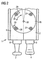
Figur 2- zeigt eine Außenansicht eines Teilbereichs der erfindungsgemäßen AndruckVorrichtung aus Figur 1,
- Figur 3
- zeigt eine Gesamtansicht der erfindungsgemäßen Andrückvorrichtung gemäß Figur 1 und
Figur 2, - Figur 4
- zeigt einen Querschnitt durch einen Blechteilabschnitt mit einem aufgesetzten Abdichtungsprofil,
Figur 5- zeigt den Blechteilabschnitt aus Figur 4 zusammen mit dem Abdichtungsprofil sowie mit einem Teilbereich einer erfindungsgemäßen Andrückvorrichtung und
Figur 6- zeigt das fertig gestellte und ängedrücke Abdichtungspröfil aus Figur 4.
- FIG. 1
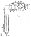
- shows a cross section through a portion of a pressing device according to the invention,
- FIG. 2
- shows an external view of a portion of the pressure device according to the invention from Figure 1,
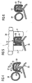
- FIG. 3
- shows an overall view of the pressing device according to the invention according to Figure 1 and Figure 2,
- FIG. 4
- shows a cross section through a sheet metal part section with an attached sealing profile,
- FIG. 5
- shows the sheet metal part section of Figure 4 together with the sealing profile and with a portion of a pressing device according to the invention and
- FIG. 6
- shows the finished and pressed-back sealing Pröfil of Figure 4.
Die Figuren 1 bis 3 zeigen eine erfindungsgemäße Andrückvorrichtung 1 in verschiedenen Darstellungen und Ansichten.Figures 1 to 3 show a pressing device 1 according to the invention in various representations and views.
Wie man besonders gut in Figur 1 sieht, gliedert sich die Andrückvorrichtung 1 in ein Antriebswellengehäuse 2, in dem eine Antriebswelle 3 mit einer Andrückrolle 4 aufgenommen ist, sowie in ein Sekundärwellengehäuse 5, in dem eine Sekundärwelle 6 mit einer Formrolle 7 aufgenommen ist. Dabei ist die Antriebswelle 3 in Antriebswellenlagern 8 gelagert und die Sekundärwelle 6 ist in Sekundärwellenlagern 9 gelagert.As can be seen particularly well in Figure 1, the pressing device 1 is divided into a
Die Antriebswelle 3 weist an ihrem in Figur 1 oben gelegenen Ende einen Antriebsvierkant 10 zum Eingriff mit einem in dieser Ansicht nicht gezeigten Pneumatikmotor auf. Im Bereich zwischen den Antriebswellenlagern 8 ist über eine Keilverbindung 11 ein Antriebszahnrad 12 vorgesehen.The drive shaft 3 has at its upper end in Figure 1 a
Das Antriebszahnrad 12 steht mit einem Sekundärzahnrad 13 in Eingriff, das über eine weitere Keilverbindung 14 auf der Sekundärwelle 6 befestigt ist. Bei einer Drehung der Antriebswelle 3 dreht sich die Sekundärwelle 6 in gleichem Maße mit.The
An der Oberseite des Antriebswellengehäuses 2 ist dieses zu einem Aufnahmeflänsch 15 verbreitert ausgebildet. Im Aufnahmeflansch 15 ist ein Druckkolbengehäuse 16 äufgenommen, das eine Durchgangsbohrung 17 sowie obenseitig einen Aufnahmeflansch 18 aufweist, der von seinen Abmessungen her mit dem Aufnahmeflansch 15 übereinstimmt.At the top of the
Das Druckkolbengehäuse weist in der in Figur 1 linksseitig gelegenen Hälfte eine Druckzylinderbohrung 19 auf, in der ein Druckkolben 20 längs verschieblich aufgenommen ist. Der Druckkolben 20 ist über eine in Figur 1 rechtsseitig an Druckkolbengehäuse 16 angeordnete Druckventilanordnung 21 betätigbär. Dabei weist die Druckventilenordnung 21 einen manuellen Betätigungsknopf 22 sowie eine Entlüftungsleitung 23 auf. Obenseitig ist, ein Druckluftanschluss 24 vorgesehen. ,In the left half of FIG. 1, the pressure piston housing has a pressure cylinder bore 19, in which a
Am Sekundärwellengehäuse 5 erstreckt sich ein Betätigungshebel 25 nach oben bis in den Bereich des Drukkolbens 20. Wie man besonders in Figur 2 und in Figur 3 sieht, ist an beiden Seiten des Antriebswellengehäuses 2 und des Sekundärwellengehäuses 5 eine Gelenkscheibe 26 angebracht. Die Gelenkscheibe 26 ist dabei mit zwei Halteschrauben 27 am Antriebswellengehäuse 2 befestigt. Am Sekundärwellengehäuse 5 sind zwei Verschiebeschrauben 28 eingeschraubt. Entsprechende Langlöcher 29 gewährleisten eine Verschiebung der Verschiebeschrauben 28 in der Ge= lenkscheibe 26. Durch diese Verschiebung wird ein Verschwenken des Sekundärwellengehäuses 5 bezüglich des An= triebswellengehäuses 2 gewährleistet, und zwar um eine Drehachse 30 herum. Dabei ist durch die Ausbildung der Andrückvorrichtung 1 gewährleistet, dass der Teilkreis des Antriebszahnrads 12 und des Sekundärzahnrads 13 im Bereich der Drehachse 30 verläuft.On the
Figur 3 zeigt die Andrückvorrichtung 1 mit eingesetztem Pneumatikmotor 31. Der Pneumatikmotor 31 hat einen Betätigungshebel 32, der die Zufuhr von Druckluft durch einen zentralen Druckluftanschluss 33 bestimmt. In einer hier nicht gezeigten Vorrichtung wird Druckluft abzweigend vom Druckluftanschluss 33 dem Druckluftanschluss 24 zuge= führt.FIG. 3 shows the pressing device 1 with inserted
Wie man weiterhin in Figur 3 besonders gut sieht, sind untenseitig am Antriebswellengehäuse 2 und am Sekundärwellengehäuse 5 zwei Querrollen 34 angebracht, von denen der besseren Darstellung wegen nur eine Querrolle 34 eingezeichnet ist. Außerdem ist im Bereich der Querrollen 34 innenseitig im Antriebswellengehäuse 2 und im Sekundärwellengehäuse 5 eine in dieser Ansicht nicht gezeigte Spreizfeder vorgesehen, die das Antriebswellengehäuse 2 und das Sekundärwellengehäuse 5 untenseitig auseinander drückt.As can be seen particularly well in Figure 3, two
In Figur 4 ist ein Abschnitt einer Karosserie 35 gezeigt, an dem eine Blechkante 36 ausgeformt ist.FIG. 4 shows a section of a
Auf die Blechkante 36 ist ein Abdichtungsprofil 37 aufgesetzt, das sich in einen Dichtschlauch 38, in einen Haltebereich 39 mit U-förmigem Querschnitt und innen liegenden Greiflippen 40 gliedert. Im Inneren des Haltebereichs 39 ist ein Blechband 41 mit U-förmigem Querschnitt eingegössen.On the
Figur 5 zeigt den Karosserieabschnitt 35 aus Figur 4 mit aufgesetzter Andrückvorrichtung 1, von der in dieser An= sicht nur die Formrolle 7, die Andrückrolle 4 und die Querrolle 34 teilweise zu sehen ist. Die Darstellung ist sehr schematisch. Wie man in dieser Darstellung gut sieht, wird das Abdichtungsprofil von der Andrückvorrichtung 1 zusammengepresst, so dass sich das Blechband 41 verformt. Dadurch treten die Greiflippen 40 in festen Eingriff mit der Blechkante 36, wodurch eine zuverlässige und gute Verbindung erreicht wird. Die erfindungsgemäße Andrückvorrichtung 1 vermeidet dabei Beschädigungen des Dichtschlauchs 38, wodurch sich später eine gute Dichtheit ergibt.Figure 5 shows the
- 11
- Andrückvorrichtungpressure device
- 22
- AntriebswellengehäuseDrive shaft housing
- 33
- Antriebswelledrive shaft
- 44
- Andrückrollecapstan
- 55
- SekundärwellengehäuseSecondary shaft housing
- 66
- Sekundärwellesecondary shaft
- 77
- Formrolleforming roller
- 88th
- AntriebswellenlagerDrive shaft bearings
- 99
- SekundärwellenlagerSecondary shaft bearing
- 1010
- AntriebsvierkantSquare Drive
- 1111
- Keilverbindungkeying
- 1212
- Antriebszahnraddrive gear
- 1313
- SekundärzahnradSecondary gear
- 1414
- Keilverbindungkeying
- 1515
- Aufnahmeflanschreceiving flange
- 1616
- DruckkolbengehäusePressure piston housing
- 1717
- DurchgangsbohrungThrough Hole
- 1818
- Aufnahmeflanschreceiving flange
- 1919
- DruckzylinderbohrungPressure cylinder bore
- 2020
- Druckkolbenpressure piston
- 2121
- DruckventilanordnungPressure valve assembly
- 2222
- Betätigungsknopfactuating button
- 2323
- Entlüftungsleitungvent line
- 2424
- DruckluftanschlussCompressed air connection
- 2525
- Betätigungshebelactuating lever
- 2626
- GelenkscheibeFlexible coupling
- 2727
- Halteschrauberetention screw
- 2828
- Verschiebeschraubeshifting screw
- 2929
- LanglochLong hole
- 3030
- Drehachseaxis of rotation
- 3131
- Pneumatikmotorpneumatic motor
- 3232
- Betätigungshebelactuating lever
- 3333
- DruckluftanschlussCompressed air connection
- 3434
- Querrollehandscroll
- 3535
- Karosseriebody
- 3636
- Blechkantemetal edge
- 3737
- Abdichtungsprofilsealing profile
- 3838
- Dichtschlauchsealing hose
- 3939
- Haltebereichholding area
- 4040
- Greiflippeengagement lip
- 4141
- Blechbandmetal strip
Claims (9)
- Press-on device (1) for fitting sealing profiles (37) in particular onto sheet-metal parts of motor vehicle bodies, having a pressing roller (4), which is driven by a pneumatically operated drive shaft (3), and having a moulding roller (7) driven via a secondary shaft (6), characterized in that drive shaft (3) and secondary shaft (6) are arranged pivotably relative to one another about a pivotal axis (30), wherein a pneumatic press-on device (20) is provided, which presses the pressing roller (4) and the moulding roller (7) towards one another.
- Press-on device according to claim 1, characterized in that the drive shaft (3) and the secondary shaft (6) are in mutual engagement via a gear stage (12, 13).
- Press-on device according to claim 2, characterized in that the gear stage comprises a driving gearwheel (12) on the drive shaft (3) and a secondary gearwheel (13) on the secondary shaft (6).
- Press-on device according to claim 3, characterized in that the pivotal axis (30) extends through a region, in which the pitch circle of the driving gearwheel (12) and the pitch circle of the secondary gearwheel (13) extends.
- Press-on device according to one of the preceding claims, characterized in that the drive shaft (3) is disposed in a drive shaft housing (2) and that the secondary shaft (6) is disposed in a secondary shaft housing (5), wherein the pneumatic press-on device comprises a piston (20), which is disposed displaceably in the drive shaft housing (2) and acts with its front end upon the second shaft housing (5).
- Press-on device according to claim 5, characterized in that the compressed-air supply to the piston (20) is connected to the compressed-air supply (33) for a drive (31) of the drive shaft (3).
- Press-on device according to claim 5 or claim 6, characterized in that for interrupting the compressed-air supply to the piston (20) a manually actuable valve (22) is provided.
- Press-on device according to claim 7, characterized in that the valve (22) comprises a vent (23) for the compressed-air supply to the piston (20).
- Press-on device according to one of claims 5 to 8, characterized in that in the region between drive shaft housing (2) and secondary shaft housing (5) a resetting spring is provided, which presses the pressing roller (4) and the moulding roller (7) away from one another.
Priority Applications (1)
| Application Number | Priority Date | Filing Date | Title |
|---|---|---|---|
| PL04011344T PL1479552T3 (en) | 2003-05-21 | 2004-05-13 | Tool for fitting channel shaped seals onto motor vehicle bodies |
Applications Claiming Priority (2)
| Application Number | Priority Date | Filing Date | Title |
|---|---|---|---|
| DE10322874A DE10322874A1 (en) | 2003-05-21 | 2003-05-21 | Pressing device for sealing profiles in motor vehicle bodies |
| DE10322874 | 2003-05-21 |
Publications (2)
| Publication Number | Publication Date |
|---|---|
| EP1479552A1 EP1479552A1 (en) | 2004-11-24 |
| EP1479552B1 true EP1479552B1 (en) | 2006-07-19 |
Family
ID=33039237
Family Applications (1)
| Application Number | Title | Priority Date | Filing Date |
|---|---|---|---|
| EP04011344A Expired - Lifetime EP1479552B1 (en) | 2003-05-21 | 2004-05-13 | Tool for fitting channel shaped seals onto motor vehicle bodies |
Country Status (4)
| Country | Link |
|---|---|
| EP (1) | EP1479552B1 (en) |
| DE (2) | DE10322874A1 (en) |
| ES (1) | ES2270220T3 (en) |
| PL (1) | PL1479552T3 (en) |
Families Citing this family (2)
| Publication number | Priority date | Publication date | Assignee | Title |
|---|---|---|---|---|
| CN111497260B (en) * | 2020-05-18 | 2022-03-29 | 华晨宝马汽车有限公司 | Sealing strip applying device and system |
| CN114654749A (en) * | 2022-03-21 | 2022-06-24 | 安徽江淮汽车集团股份有限公司 | Rolling device for assisting in assembling automobile door frame adhesive tape |
Family Cites Families (3)
| Publication number | Priority date | Publication date | Assignee | Title |
|---|---|---|---|---|
| GB2324327B (en) * | 1997-04-18 | 2001-06-13 | Standard Prod Ltd | Clinching tool with rotatable spindles driven by a worm and gear |
| GB2327698B (en) * | 1997-07-25 | 2001-08-01 | Draftex Ind Ltd | Strip fitting tools and methods |
| GB9820965D0 (en) * | 1998-09-25 | 1998-11-18 | Draftex Ind Ltd | Strip fitting tools and methods |
-
2003
- 2003-05-21 DE DE10322874A patent/DE10322874A1/en not_active Withdrawn
-
2004
- 2004-05-13 PL PL04011344T patent/PL1479552T3/en unknown
- 2004-05-13 EP EP04011344A patent/EP1479552B1/en not_active Expired - Lifetime
- 2004-05-13 ES ES04011344T patent/ES2270220T3/en not_active Expired - Lifetime
- 2004-05-13 DE DE502004000973T patent/DE502004000973D1/en not_active Expired - Lifetime
Also Published As
| Publication number | Publication date |
|---|---|
| PL1479552T3 (en) | 2006-09-29 |
| ES2270220T3 (en) | 2007-04-01 |
| EP1479552A1 (en) | 2004-11-24 |
| DE502004000973D1 (en) | 2006-08-31 |
| DE10322874A1 (en) | 2004-12-30 |
Similar Documents
| Publication | Publication Date | Title |
|---|---|---|
| DE3153293C2 (en) | Automatically pressing sealing arrangement for the window pane of a vertically movable vehicle window | |
| DE2806117C2 (en) | Electrically operated window drive, especially for motor vehicles | |
| DE102010021431B4 (en) | Device for engaging a flange cover with a flange | |
| DE69011473T2 (en) | Rubber seals and processes for their manufacture. | |
| DE3922866A1 (en) | SEALING STRIP | |
| WO1999048714A1 (en) | Sealing profile for motor vehicles | |
| WO2007113042A1 (en) | Inflatable sealing device for a die | |
| EP2232108B1 (en) | Closure device for tightly closing a filling and emptying system of railway tank cars or transportation tanks | |
| EP1126938A1 (en) | Bordering and/or crease-closing machine and method for operating the same | |
| DE2638684C3 (en) | Actuating device for the closure cover of a motor vehicle sliding roof | |
| DE69103389T2 (en) | Sealing device. | |
| EP1193098A2 (en) | Sealing system for a support lever on an openable vehicle roof | |
| EP1479552B1 (en) | Tool for fitting channel shaped seals onto motor vehicle bodies | |
| DE102005059201B4 (en) | pump connection | |
| DE1963309A1 (en) | Device on sliding doors | |
| DE4409935A1 (en) | Rail-bound vehicle | |
| DE69710563T2 (en) | Device for attaching sealing lips | |
| DE10227138A1 (en) | Cover for a ball joint | |
| DE69201030T2 (en) | Diaphragm feed pump with steered drive lever. | |
| DE4327067A1 (en) | Mounting device for a sealing profile to be pushed onto a flange | |
| DE2605588B2 (en) | Locking device for the mouth of the key channel of a cylinder lock, in particular for motor vehicles | |
| DE20308337U1 (en) | Fluid application device | |
| EP1955884B1 (en) | Device for attaching a sealing strip to an automobile body | |
| EP0443455B2 (en) | Pivoting device for anti-skid chain assembly | |
| DE10301584A1 (en) | Closure device for sliding panel, especially vehicle window, has profiled rolls cooperating with profiling on guide rails |
Legal Events
| Date | Code | Title | Description |
|---|---|---|---|
| PUAI | Public reference made under article 153(3) epc to a published international application that has entered the european phase |
Free format text: ORIGINAL CODE: 0009012 |
|
| AK | Designated contracting states |
Kind code of ref document: A1 Designated state(s): AT BE BG CH CY CZ DE DK EE ES FI FR GB GR HU IE IT LI LU MC NL PL PT RO SE SI SK TR |
|
| AX | Request for extension of the european patent |
Extension state: AL HR LT LV MK |
|
| 17P | Request for examination filed |
Effective date: 20050523 |
|
| AKX | Designation fees paid |
Designated state(s): AT BE BG CH CY CZ DE DK EE ES FI FR GB GR HU IE IT LI LU MC NL PL PT RO SE SI SK TR |
|
| GRAP | Despatch of communication of intention to grant a patent |
Free format text: ORIGINAL CODE: EPIDOSNIGR1 |
|
| GRAS | Grant fee paid |
Free format text: ORIGINAL CODE: EPIDOSNIGR3 |
|
| GRAA | (expected) grant |
Free format text: ORIGINAL CODE: 0009210 |
|
| AK | Designated contracting states |
Kind code of ref document: B1 Designated state(s): CZ DE ES FR GB PL SK |
|
| REG | Reference to a national code |
Ref country code: GB Ref legal event code: FG4D Free format text: NOT ENGLISH |
|
| REF | Corresponds to: |
Ref document number: 502004000973 Country of ref document: DE Date of ref document: 20060831 Kind code of ref document: P |
|
| GBT | Gb: translation of ep patent filed (gb section 77(6)(a)/1977) |
Effective date: 20060824 |
|
| ET | Fr: translation filed | ||
| REG | Reference to a national code |
Ref country code: ES Ref legal event code: FG2A Ref document number: 2270220 Country of ref document: ES Kind code of ref document: T3 |
|
| PLBE | No opposition filed within time limit |
Free format text: ORIGINAL CODE: 0009261 |
|
| STAA | Information on the status of an ep patent application or granted ep patent |
Free format text: STATUS: NO OPPOSITION FILED WITHIN TIME LIMIT |
|
| 26N | No opposition filed |
Effective date: 20070420 |
|
| REG | Reference to a national code |
Ref country code: GB Ref legal event code: 732E Free format text: REGISTERED BETWEEN 20090219 AND 20090225 |
|
| REG | Reference to a national code |
Ref country code: GB Ref legal event code: 732E Free format text: REGISTERED BETWEEN 20090305 AND 20090311 |
|
| REG | Reference to a national code |
Ref country code: GB Ref legal event code: 732E Free format text: REGISTERED BETWEEN 20091029 AND 20091104 |
|
| REG | Reference to a national code |
Ref country code: GB Ref legal event code: 732E Free format text: REGISTERED BETWEEN 20091105 AND 20091111 |
|
| REG | Reference to a national code |
Ref country code: DE Ref legal event code: R081 Ref document number: 502004000973 Country of ref document: DE Owner name: GM GLOBAL TECHNOLOGY OPERATIONS LLC (N. D. GES, US Free format text: FORMER OWNER: GM GLOBAL TECHNOLOGY OPERATIONS, INC., DETROIT, MICH., US Effective date: 20110323 Ref country code: DE Ref legal event code: R081 Ref document number: 502004000973 Country of ref document: DE Owner name: GM GLOBAL TECHNOLOGY OPERATIONS LLC (N. D. GES, US Free format text: FORMER OWNER: GM GLOBAL TECHNOLOGY OPERATIONS, INC., DETROIT, US Effective date: 20110323 |
|
| REG | Reference to a national code |
Ref country code: FR Ref legal event code: PLFP Year of fee payment: 13 |
|
| PGFP | Annual fee paid to national office [announced via postgrant information from national office to epo] |
Ref country code: CZ Payment date: 20160505 Year of fee payment: 13 Ref country code: GB Payment date: 20160511 Year of fee payment: 13 Ref country code: DE Payment date: 20160510 Year of fee payment: 13 Ref country code: ES Payment date: 20160414 Year of fee payment: 13 |
|
| PGFP | Annual fee paid to national office [announced via postgrant information from national office to epo] |
Ref country code: PL Payment date: 20160404 Year of fee payment: 13 Ref country code: FR Payment date: 20160412 Year of fee payment: 13 Ref country code: SK Payment date: 20160405 Year of fee payment: 13 |
|
| REG | Reference to a national code |
Ref country code: DE Ref legal event code: R119 Ref document number: 502004000973 Country of ref document: DE |
|
| GBPC | Gb: european patent ceased through non-payment of renewal fee |
Effective date: 20170513 |
|
| PG25 | Lapsed in a contracting state [announced via postgrant information from national office to epo] |
Ref country code: CZ Free format text: LAPSE BECAUSE OF NON-PAYMENT OF DUE FEES Effective date: 20170513 Ref country code: SK Free format text: LAPSE BECAUSE OF NON-PAYMENT OF DUE FEES Effective date: 20170513 |
|
| REG | Reference to a national code |
Ref country code: SK Ref legal event code: MM4A Ref document number: E 1068 Country of ref document: SK Effective date: 20170513 |
|
| REG | Reference to a national code |
Ref country code: FR Ref legal event code: ST Effective date: 20180131 |
|
| PG25 | Lapsed in a contracting state [announced via postgrant information from national office to epo] |
Ref country code: DE Free format text: LAPSE BECAUSE OF NON-PAYMENT OF DUE FEES Effective date: 20171201 Ref country code: GB Free format text: LAPSE BECAUSE OF NON-PAYMENT OF DUE FEES Effective date: 20170513 |
|
| PG25 | Lapsed in a contracting state [announced via postgrant information from national office to epo] |
Ref country code: FR Free format text: LAPSE BECAUSE OF NON-PAYMENT OF DUE FEES Effective date: 20170531 |
|
| REG | Reference to a national code |
Ref country code: ES Ref legal event code: FD2A Effective date: 20180705 |
|
| PG25 | Lapsed in a contracting state [announced via postgrant information from national office to epo] |
Ref country code: ES Free format text: LAPSE BECAUSE OF NON-PAYMENT OF DUE FEES Effective date: 20170514 |
|
| PG25 | Lapsed in a contracting state [announced via postgrant information from national office to epo] |
Ref country code: PL Free format text: LAPSE BECAUSE OF NON-PAYMENT OF DUE FEES Effective date: 20170513 |