EP2232108B1 - Closure device for tightly closing a filling and emptying system of railway tank cars or transportation tanks - Google Patents
Closure device for tightly closing a filling and emptying system of railway tank cars or transportation tanks Download PDFInfo
- Publication number
- EP2232108B1 EP2232108B1 EP09700154A EP09700154A EP2232108B1 EP 2232108 B1 EP2232108 B1 EP 2232108B1 EP 09700154 A EP09700154 A EP 09700154A EP 09700154 A EP09700154 A EP 09700154A EP 2232108 B1 EP2232108 B1 EP 2232108B1
- Authority
- EP
- European Patent Office
- Prior art keywords
- closure
- pipe connection
- connection piece
- closure cap
- closure device
- Prior art date
- Legal status (The legal status is an assumption and is not a legal conclusion. Google has not performed a legal analysis and makes no representation as to the accuracy of the status listed.)
- Not-in-force
Links
Images


Classifications
-
- F—MECHANICAL ENGINEERING; LIGHTING; HEATING; WEAPONS; BLASTING
- F16—ENGINEERING ELEMENTS AND UNITS; GENERAL MEASURES FOR PRODUCING AND MAINTAINING EFFECTIVE FUNCTIONING OF MACHINES OR INSTALLATIONS; THERMAL INSULATION IN GENERAL
- F16J—PISTONS; CYLINDERS; SEALINGS
- F16J13/00—Covers or similar closure members for pressure vessels in general
- F16J13/02—Detachable closure members; Means for tightening closures
- F16J13/12—Detachable closure members; Means for tightening closures attached by wedging action by means of screw-thread, interrupted screw-thread, bayonet closure, or the like
-
- B—PERFORMING OPERATIONS; TRANSPORTING
- B65—CONVEYING; PACKING; STORING; HANDLING THIN OR FILAMENTARY MATERIAL
- B65D—CONTAINERS FOR STORAGE OR TRANSPORT OF ARTICLES OR MATERIALS, e.g. BAGS, BARRELS, BOTTLES, BOXES, CANS, CARTONS, CRATES, DRUMS, JARS, TANKS, HOPPERS, FORWARDING CONTAINERS; ACCESSORIES, CLOSURES, OR FITTINGS THEREFOR; PACKAGING ELEMENTS; PACKAGES
- B65D39/00—Closures arranged within necks or pouring openings or in discharge apertures, e.g. stoppers
- B65D39/12—Closures arranged within necks or pouring openings or in discharge apertures, e.g. stoppers expansible, e.g. inflatable
-
- B—PERFORMING OPERATIONS; TRANSPORTING
- B65—CONVEYING; PACKING; STORING; HANDLING THIN OR FILAMENTARY MATERIAL
- B65D—CONTAINERS FOR STORAGE OR TRANSPORT OF ARTICLES OR MATERIALS, e.g. BAGS, BARRELS, BOTTLES, BOXES, CANS, CARTONS, CRATES, DRUMS, JARS, TANKS, HOPPERS, FORWARDING CONTAINERS; ACCESSORIES, CLOSURES, OR FITTINGS THEREFOR; PACKAGING ELEMENTS; PACKAGES
- B65D41/00—Caps, e.g. crown caps or crown seals, i.e. members having parts arranged for engagement with the external periphery of a neck or wall defining a pouring opening or discharge aperture; Protective cap-like covers for closure members, e.g. decorative covers of metal foil or paper
- B65D41/02—Caps or cap-like covers without lines of weakness, tearing strips, tags, or like opening or removal devices
- B65D41/28—Caps combined with stoppers
-
- B—PERFORMING OPERATIONS; TRANSPORTING
- B65—CONVEYING; PACKING; STORING; HANDLING THIN OR FILAMENTARY MATERIAL
- B65D—CONTAINERS FOR STORAGE OR TRANSPORT OF ARTICLES OR MATERIALS, e.g. BAGS, BARRELS, BOTTLES, BOXES, CANS, CARTONS, CRATES, DRUMS, JARS, TANKS, HOPPERS, FORWARDING CONTAINERS; ACCESSORIES, CLOSURES, OR FITTINGS THEREFOR; PACKAGING ELEMENTS; PACKAGES
- B65D90/00—Component parts, details or accessories for large containers
- B65D90/54—Gates or closures
- B65D90/545—Discharge end caps
-
- F—MECHANICAL ENGINEERING; LIGHTING; HEATING; WEAPONS; BLASTING
- F16—ENGINEERING ELEMENTS AND UNITS; GENERAL MEASURES FOR PRODUCING AND MAINTAINING EFFECTIVE FUNCTIONING OF MACHINES OR INSTALLATIONS; THERMAL INSULATION IN GENERAL
- F16J—PISTONS; CYLINDERS; SEALINGS
- F16J15/00—Sealings
- F16J15/02—Sealings between relatively-stationary surfaces
- F16J15/021—Sealings between relatively-stationary surfaces with elastic packing
- F16J15/028—Sealings between relatively-stationary surfaces with elastic packing the packing being mechanically expanded against the sealing surface
-
- F—MECHANICAL ENGINEERING; LIGHTING; HEATING; WEAPONS; BLASTING
- F16—ENGINEERING ELEMENTS AND UNITS; GENERAL MEASURES FOR PRODUCING AND MAINTAINING EFFECTIVE FUNCTIONING OF MACHINES OR INSTALLATIONS; THERMAL INSULATION IN GENERAL
- F16L—PIPES; JOINTS OR FITTINGS FOR PIPES; SUPPORTS FOR PIPES, CABLES OR PROTECTIVE TUBING; MEANS FOR THERMAL INSULATION IN GENERAL
- F16L55/00—Devices or appurtenances for use in, or in connection with, pipes or pipe systems
- F16L55/10—Means for stopping flow from or in pipes or hoses
- F16L55/115—Caps
- F16L55/1152—Caps fixed by screwing or by means of a screw-threaded ring
-
- F—MECHANICAL ENGINEERING; LIGHTING; HEATING; WEAPONS; BLASTING
- F16—ENGINEERING ELEMENTS AND UNITS; GENERAL MEASURES FOR PRODUCING AND MAINTAINING EFFECTIVE FUNCTIONING OF MACHINES OR INSTALLATIONS; THERMAL INSULATION IN GENERAL
- F16L—PIPES; JOINTS OR FITTINGS FOR PIPES; SUPPORTS FOR PIPES, CABLES OR PROTECTIVE TUBING; MEANS FOR THERMAL INSULATION IN GENERAL
- F16L55/00—Devices or appurtenances for use in, or in connection with, pipes or pipe systems
- F16L55/10—Means for stopping flow from or in pipes or hoses
- F16L55/12—Means for stopping flow from or in pipes or hoses by introducing into the pipe a member expandable in situ
- F16L55/128—Means for stopping flow from or in pipes or hoses by introducing into the pipe a member expandable in situ introduced axially into the pipe or hose
- F16L55/1286—The closing device being a cap
-
- F—MECHANICAL ENGINEERING; LIGHTING; HEATING; WEAPONS; BLASTING
- F16—ENGINEERING ELEMENTS AND UNITS; GENERAL MEASURES FOR PRODUCING AND MAINTAINING EFFECTIVE FUNCTIONING OF MACHINES OR INSTALLATIONS; THERMAL INSULATION IN GENERAL
- F16L—PIPES; JOINTS OR FITTINGS FOR PIPES; SUPPORTS FOR PIPES, CABLES OR PROTECTIVE TUBING; MEANS FOR THERMAL INSULATION IN GENERAL
- F16L55/00—Devices or appurtenances for use in, or in connection with, pipes or pipe systems
- F16L55/10—Means for stopping flow from or in pipes or hoses
- F16L55/12—Means for stopping flow from or in pipes or hoses by introducing into the pipe a member expandable in situ
- F16L55/128—Means for stopping flow from or in pipes or hoses by introducing into the pipe a member expandable in situ introduced axially into the pipe or hose
- F16L55/132—Means for stopping flow from or in pipes or hoses by introducing into the pipe a member expandable in situ introduced axially into the pipe or hose the closure device being a plug fixed by radially deforming the packing
-
- B—PERFORMING OPERATIONS; TRANSPORTING
- B65—CONVEYING; PACKING; STORING; HANDLING THIN OR FILAMENTARY MATERIAL
- B65D—CONTAINERS FOR STORAGE OR TRANSPORT OF ARTICLES OR MATERIALS, e.g. BAGS, BARRELS, BOTTLES, BOXES, CANS, CARTONS, CRATES, DRUMS, JARS, TANKS, HOPPERS, FORWARDING CONTAINERS; ACCESSORIES, CLOSURES, OR FITTINGS THEREFOR; PACKAGING ELEMENTS; PACKAGES
- B65D2251/00—Details relating to container closures
- B65D2251/0003—Two or more closures
- B65D2251/0006—Upper closure
- B65D2251/0015—Upper closure of the 41-type
-
- B—PERFORMING OPERATIONS; TRANSPORTING
- B65—CONVEYING; PACKING; STORING; HANDLING THIN OR FILAMENTARY MATERIAL
- B65D—CONTAINERS FOR STORAGE OR TRANSPORT OF ARTICLES OR MATERIALS, e.g. BAGS, BARRELS, BOTTLES, BOXES, CANS, CARTONS, CRATES, DRUMS, JARS, TANKS, HOPPERS, FORWARDING CONTAINERS; ACCESSORIES, CLOSURES, OR FITTINGS THEREFOR; PACKAGING ELEMENTS; PACKAGES
- B65D2251/00—Details relating to container closures
- B65D2251/0003—Two or more closures
- B65D2251/0068—Lower closure
- B65D2251/0075—Lower closure of the 39-type
Definitions
- the invention relates to a closure device for sealing a pipe socket of a filling and emptying system of rail tank cars, a closure device having the filling and emptying system of rail tank cars and a method for operating the closure device.
- closures of rail tank cars or transport tanks which are usually designed as screw caps, constitute a closure measure provided in addition to a first and second existing closure device, which is attached to the end of the pipe socket and a loss of a transported liquid or the residues of a liquid remaining in the filling and emptying system should prevent.
- the closure device at the end of a pipe socket conventionally has a screw cap which, when screwed on, seals the end of the pipe socket of the valve housing designed as a sealing surface by means of an inserted flat gasket.
- the conventional screw cap seals the sealing surface or the completion of a pipe socket only by means of the flat gasket. Damage (for example notches) on this sealing surface of the nozzle and defective flat gaskets can lead to leaks or drip leaks.
- the European dangerous goods law for railway traffic (RID) demands u. a. the tightness of rail tank cars during operation. This is not necessarily achievable with existing technical solutions, as proven in many cases.
- a generic closure device is known from eg GB 771,261 ,
- the invention has for its object to provide a closure device for a filling and emptying system and a method for operating the same, with which a tightness of the closure is guaranteed reliable and during the lifelong operating life of the closure.
- the prevention of mechanical squeezing of the seal and a defined tightness with easy operability of the cap are a further object of the invention.
- the manufacturing tolerances caused by deviations of the internal dimensions of the pipe socket connections of filling and emptying pipe systems should also be compensated.
- the invention is based on a device-related aspect of a closure device for sealing a pipe socket connection of a filling and emptying system of rail tank cars or transport tanks, which has a preferably designed as a screw cap with a cap on a front side of the pipe socket attacking seal element. At least one additional sealing element mounted on the closure cap is configured such that it can be frictionally engaged with the inner wall of a pipe stub.
- the closure cap is designed as a screw cap
- the sealing element attached to the closure cap has at least one substantially annular seal, which can be frictionally engaged with the inner wall of the tube nozzle
- the gasket acting on a arranged on the cap retaining pin is plugged and supported by means of a terminal connected to the retaining bolt pressure plate
- the retaining bolt in the axial direction relative to the cap is movably mounted, wherein by its movement towards the cap, the pressure plate on the annular seal exerts a compressive force, which the annular seal bulges radially outwardly, so that the seal with the inner wall of the pipe socket in a frictional engagement can be brought and the displacement of the retaining bolt relative to the cap using an inn Heen threaded connection is executed, which is formed between the retaining bolt and a clamping device.
- the annular seal is at least one piece and supported by means of the fixedly connected to the retaining bolt pressure plate against slipping of the retaining bolt.
- the retaining bolt is slidably mounted on the cap so that it is movable in the axial direction relative to the closure cap, wherein the pressure plate exerts a compressive force on the annular seal by its movement in the direction of the closure cap so that the annular seal against the inner wall of the closure cap is pressed and compressed and elastically deformed such that the diameter of the annular seal widened and the annular seal with the inner wall of the pipe socket engages in a frictional engagement.
- the internal threaded connection formed between the retainer pin and a tensioner requires the user to apply smaller closing actuation forces while still allowing a very high closing force to be achieved because the mechanical ratio of a threaded connection is known to be very high.
- the additional, preferably annular sealing element acts on the inner wall of the pipe socket with a predetermined and / or predeterminable pressure force. This can prevent that overloading of the closure by excessive closing forces leads to its damage and consequently a malfunction.
- At least the contact region of the additional sealing element made of an elastic plastic, such as polytetravinyl chloride, polytetrafluoroethylene (PTFE), polyurethane, silicone, rubber, rubber, or another elastomer, whereby a high density can be achieved even with an uneven inner wall of the pipe socket to be closed can.
- an elastic plastic such as polytetravinyl chloride, polytetrafluoroethylene (PTFE), polyurethane, silicone, rubber, rubber, or another elastomer
- the additional sealing element is mounted exchangeably on the cap. This allows, After a certain period of use or after damage, replace the old sealing element with a new one.
- the inner wall of the pipe socket is formed according to a further preferred embodiment of the present invention tapers from outside to inside and the seal attached to the cap has a corresponding thereto tapered outer shape.
- the seal attached to the cap has a corresponding thereto tapered outer shape.
- the inner wall of the pipe socket is cylindrical in an alternative preferred embodiment of the present invention and the sealing element attached to the closure cap has a substantially cylindrical outer shape corresponding thereto , This allows the use of the closure device according to the invention in existing systems in cylindrical inner walls of the pipe socket of the valves, whereby high investment costs are avoided.
- the diameter of the annular seal is preferably predetermined so that a slight introduction into the opening of the pipe socket and at the same time a frictional contact with its inner wall is made possible.
- the frictional contact between the annular seal and the inner wall of the pipe socket ensures that the annular seal is held against rotation, which can occur as a result of the applied rotational clamping forces.
- the tensioning device is rotatably mounted in or on the closure cap.
- the rotary actuation of the additional sealing element according to the invention is decoupled from the rotation of the closure cap, so that both the conventional sealing means in the form of an end-face gasket and the additional sealing element according to the invention can be effective independently of one another.
- At least two annular seals are placed one behind the other on the retaining bolt.
- the objects of the invention are achieved by means of a filling and emptying system of rail tank cars or transport tanks with a closure device according to the invention as described above.
- a procedural aspect of the present invention relates to a method for operating or operating the closure device according to one of the embodiments described above in a filling and emptying system of rail tank cars or transport tanks.
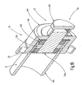
- FIGS 1A and 1B show a first preferred embodiment of a total of 50 designated inventive closure device.
- the closure device 50 has a closure cap 30, which is screwed to a pipe connection 10, in particular to its pipe socket 102, a filling and emptying system (not shown) of rail tank cars or transport tanks by means of a threaded connection 105.
- the closure device 50 may have a conventional flat gasket 106 with which an inner wall of the closure cap 30 can be sealed on an end face 104 of the pipe socket 102.
- the closure device 50 may be used without a gasket 106.
- a tensioning device 40 is mounted rotatably mounted, which has a turntable 403 and a handle cap 402.
- the turntable 403 allows on the one hand a centering of the handle cap 402 relative to the housing 301 of the cap, which is designed in particular as a screw cap 30, and on the other hand, a rotation of these two parts. It occurs between the turntable 403 and the screw cap 30 preferably has a relatively low sliding friction.
- the handle cap 402 is provided for a manual turning operation by a user and, in this embodiment, has a threaded connection 401 designed as an internal thread with which a retaining bolt 204 equipped with an external thread is screwed.
- This retaining bolt 204 serves as a carrier for the case of this two-part sealing element 20, which preferably has two annular seals 202 and 203.
- the annular seals 202 and 203 are preferably mounted on the retaining bolt 204 and a spacer 205 is slidably disposed therebetween on the retaining bolt 204.
- the illustrated state of the closure device or closure 50 is shown in a not yet tensioned state of the tensioning device 40, after the retaining bolt 204 with the plugged on it annular seals 202, 203 inserted into an opening 101 of the pipe socket 102 while the housing 301 of the screw cap 30th has been screwed onto the pipe socket 102 by means of the threaded connection 105. So that the retaining bolt 204 with the attached thereto annular seals 202, 203 is not rotated with the handle cap 402 - for example due to contamination increased thread frictional forces - the diameter of the annular seals 202, 203 is selected so that the seals already in the untensioned Condition in a frictional connection with the inner wall 103 of the pipe socket 102 occur.
- the Indian FIG. 1 gap shown between the inner wall of the pipe socket 102 and the seals 202, 203 is merely a better representation and is actually not present.
- the retaining bolt 204 remains untwisted during manual rotation of the handle cap 402, thereby compressing the annular seals 202, 203 press even more firmly against the inner wall 103 of the pipe socket 102 and the seal can thus be made very dense with increasing frictional and compressive forces.
- the clamping device 40 To close the closure 50, the clamping device 40 must be manually rotated in the closing direction, so that the retaining bolt 204 is retracted into the cavity of the handle cap 402 by the translation of the threaded connection 401.
- a pressure plate 201 arranged terminally on the retaining bolt 204 exerts a compressive force on the first annular seal 202, which in turn transmits this pressure force to the spacer 205, which itself slidingly transmits on the retaining bolt 204 the thrust thus obtained to the second annular seal 203 ,
- the two annular seals 202 and 203 are compressed, whereby their outer sides are bulged and attack against the inner wall 103 of the pipe socket 102 with a certain force.
- the amount of this force can be limited by design such that an operator can feel a very high counterforce before, for example, the threaded connection 401 is overstressed.
- the elastic deformation of the annular seals 202 and 203 which are made of an elastomer, creates a frictional and therefore a highly tight connection between the inner wall 103 of the pipe socket 102 and the seals.
- the seals 202, 203 are simultaneously sealed by the same pressure forces against the retaining bolt 204, which they engage around non-positively.
- small dents in the inner wall 103 of the pipe socket 102 which may occur in the course of its useful life, be compensated by the elastic material of the one or both annular seals 202, 203.
- the probability that a too large dent reduces the sealing function of one of the two annular seals in that the seals 202, 203 are used multiple times and that between them by the spacer 205 a distance is created.
- FIG. 2 shows an embodiment of a non-inventive closure 50, wherein like elements are denoted by the same reference numerals and will not be explained again in detail. It is a comparison with the execution in FIG. 1 simplified solution that manages with fewer parts and therefore is cheaper to produce.
- the sealing element 20 has a one-piece stopper 206, which is made of an elastomer.
- This elastic plug 206 preferably has a dimension that is as long as possible in its length, so that it forms a larger, force-fitting attacking surface.
- This engagement surface acts only by the biasing force of the elastic plug 206, which for this purpose has a slightly larger diameter than the inner diameter of the pipe socket 102.
- the plug 206 is for closing the closure 50 is first manually inserted into the opening 101 of the pipe socket 102, wherein in order to facilitate insertion of the diameter of the plug 206 may be selected slightly smaller at its end.
- the plug 206 does not need to be rotated with the screw cap 30, but rotates freely with respect to this, which is why the plug 206 is rotatably mounted on the screw cap 30 by means of a rotation axis 404.
- the opening 101 of the pipe socket 102 has a tapered, tapered inner wall 103, whereby the plug 206 can reach a particularly frictional contact with this inner wall.
- the disadvantage is that an exchange of a conventional pipe socket must be made against a new tapered inner wall, if this pipe stub construction is not present, which entails an increased cost.
- a part already used valves already has an inner wall tapered in this form, so that the illustrated solution is directly applicable for these cases.
- the alternative embodiment provides to use the more common pipe socket 102 with cylindrical opening 101, d. H. to introduce the plug 206 into the cylindrical opening 101.
- the tightness is achieved here only by the predetermined by means of the elastic material of the plug 206 biasing force, similar to a bottle cork.
- the handle cap 402 is firmly connected to the screw cap 30 in this embodiment and serves with its smaller diameter easier manual rotation of the screw cap 30th
- FIG. 3 shows a conventional closure device with a conventional cap or screw cap 30 with a flat gasket 106.
- This conventional solution has a flat sealant 106 which between the end face 104 of Pipe socket 102 and the flat inner wall of the cap 30 by means of the threaded connection 105 is frictionally brought into abutment.
- the handle cap 402 is used for faster rotation of the screw cap 30, while a larger closing or opening torque can be generated by turning on the outer surface of the screw cap with its larger diameter.
- This conventional seal is subject to the wear described above, which leads to leaks.
Abstract
Description
Die Erfindung betrifft eine Verschlusseinrichtung zum dichten Verschließen eines Rohrstutzens eines Füll- und Entleerungssystems von Eisenbahnkesselwagen, ein die Verschlusseinrichtung aufweisendes Füll- und Entleerungssystem von Eisenbahnkesselwagen und ein Verfahren zum Bedienen der Verschlusseinrichtung.The invention relates to a closure device for sealing a pipe socket of a filling and emptying system of rail tank cars, a closure device having the filling and emptying system of rail tank cars and a method for operating the closure device.
Diversen Untersuchungsberichten und Statistiken aus den behördlichen Gefahrgutkontrollen zufolge existieren in der Praxis entgegen Anforderungen der Gefahrguttransportvorschriften und auch entgegen begleitenden Vorschriften Undichtigkeiten an den Eisenbahnkesselwagen in Form von Tropfleckagen. Die Tropfleckagen entstehen in den meisten Fällen durch Restmengen im Füll- und Entleerungssystem der Kesselwagen in Verbindung mit unzureichend verschlossenen Verschlusseinrichtungen.According to various investigation reports and statistics from the official hazardous goods inspections, in practice, contrary to the requirements of the dangerous goods transport regulations and also contrary regulations, there are leaks in the rail tanker cars in the form of drip leaks. In most cases, the drip leaks are caused by residual amounts in the filling and emptying system of the tank wagon in connection with insufficiently closed locking devices.
Die zumeist als Schraubkappen ausgeführten Verschlüsse von Eisenbahnkesselwagen bzw. Transporttanks stellen eine zusätzlich zu einer ersten und zweiten vorhandenen Verschlusseinrichtung vorgesehene Verschlussmaßnahme dar, die am Ende des Rohrstutzens angebracht ist und einen Verlust einer transportierten Flüssigkeit bzw. der im Füll- und Entleerungssystem zurückbleibenden Reste einer Flüssigkeit verhindern soll.The closures of rail tank cars or transport tanks, which are usually designed as screw caps, constitute a closure measure provided in addition to a first and second existing closure device, which is attached to the end of the pipe socket and a loss of a transported liquid or the residues of a liquid remaining in the filling and emptying system should prevent.
Die Verschlusseinrichtung am Ende eines Rohrstutzens weist konventionell eine Schraubkappe auf, die im aufgeschraubten Zustand mittels einer eingelegten Flachdichtung den als Dichtfläche ausgeführten Abschluss des Rohrstutzens des Ventilgehäuses abdichtet. Die herkömmliche Schraubkappe dichtet die Dichtfläche bzw. den Abschluss eines Rohrstutzens jedoch nur mittels der Flachdichtung ab. Beschädigungen (z.B. Kerben) auf dieser Dichtfläche des Stutzens und schadhafte Flachdichtungen können zu Undichtigkeiten bzw. Tropfleckagen führen. Das europäische Gefahrgutrecht für den Eisenbahnverkehr (RID) fordert u. a. die Dichtheit von Eisenbahnkesselwagen während des Betriebs. Diese ist mit bestehenden technischen Lösungen, wie in vielen Fällen nachgewiesen, nicht zwangsläufig erreichbar.The closure device at the end of a pipe socket conventionally has a screw cap which, when screwed on, seals the end of the pipe socket of the valve housing designed as a sealing surface by means of an inserted flat gasket. However, the conventional screw cap seals the sealing surface or the completion of a pipe socket only by means of the flat gasket. Damage (for example notches) on this sealing surface of the nozzle and defective flat gaskets can lead to leaks or drip leaks. The European dangerous goods law for railway traffic (RID) demands u. a. the tightness of rail tank cars during operation. This is not necessarily achievable with existing technical solutions, as proven in many cases.
Es ist bekannt, dass die Form der Innenwandung eines Rohrstutzens zylindrisch, aber auch bei einigen Ausführungen verjüngend zulaufend ausgestaltet sein kann. Eine Schwachstelle besteht nun in den durch Fertigungstoleranzen entstandenen Abweichungen der Innenabmessungen der Rohrstutzen, weil diese Abmessungen bislang funktionell keine sehr hohe Genauigkeit aufzuweisen hatten.It is known that the shape of the inner wall of a pipe socket can be designed to be cylindrical, but also tapering in some embodiments. A weak spot exists now in the resulting by manufacturing tolerances deviations of the inner dimensions of the pipe socket, because these dimensions have so far had functionally not very high accuracy.
Eine gattungsgemäße Verschlusseinrichtung ist bekannt aus z.B.
Der Erfindung liegt die Aufgabe zugrunde, eine Verschlusseinrichtung für ein Füll- und Entleerungssystem und ein Verfahren zum Bedienen derselben vorzuschlagen, mit welchen eine Dichtheit des Verschlusses zuverlässig und während der lebenslangen Betriebsdauer des Verschlusses gewährleistet ist. Das Verhindern eines mechanischen Quetschens der Dichtung und eine definierte Dichtheit bei einer leichten Bedienbarkeit der Verschlusskappe sind eine weitere Aufgaben der Erfindung. Die durch Fertigungstoleranzen bedingten Abweichungen der inneren Abmessungen der Rohrstutzenanschlüsse von Füll- und Entleerungsrohrsystemen sollen ferner kompensiert werden.The invention has for its object to provide a closure device for a filling and emptying system and a method for operating the same, with which a tightness of the closure is guaranteed reliable and during the lifelong operating life of the closure. The prevention of mechanical squeezing of the seal and a defined tightness with easy operability of the cap are a further object of the invention. The manufacturing tolerances caused by deviations of the internal dimensions of the pipe socket connections of filling and emptying pipe systems should also be compensated.
Die Erfindung geht nach einem vorrichtungsmäßigen Aspekt von einer Verschlusseinrichtung zum dichten Verschließen eines Rohrstutzenanschlusses eines Füll- und Entleerungssystems von Eisenbahnkesselwagen oder Transporttanks aus, die eine vorzugsweise als Schraubkappe ausgeführte Verschlusskappe mit einem an einer Stirnseite des Rohrstutzens in Angriff bringbaren Dichtungselement aufweist. Wenigstens ein an der Verschlusskappe angebautes zusätzliches Dichtungselement ist so ausgestaltet, dass es mit der Innenwand eines Rohrstutzens in einen kraftschlüssigen Eingriff gebracht werden kann. Die Aufgaben der vorliegenden Erfindung werden dadurch gelöst, dass die Verschlusskappe als Schraubkappe ausgestaltet ist, und das an der Verschlusskappe angebaute Dichtungselement wenigstens eine im Wesentlichen ringförmige Dichtung aufweist, die mit der Innenwand des Rohrstutzens in einen kraftschlüssigen Eingriff bringbar ist, wobei die Dichtung auf einen an der Verschlusskappe angeordneten Haltebolzen aufgesteckt ist und mithilfe einer endständig mit dem Haltebolzen verbundenen Druckplatte abgestützt ist, und der Haltebolzen in axialer Richtung gegenüber der Verschlusskappe bewegbar angebracht ist, wobei durch seine Bewegung in Richtung Verschlusskappe die Druckplatte auf die ringförmige Dichtung eine Druckkraft ausübt, welche die ringförmige Dichtung radial nach außen aufwölbt, so dass die Dichtung mit der Innenwandung des Rohrstutzens in einen kraftschlüssigen Eingriff bringbar ist und die Verschiebung des Haltebolzens gegenüber der Verschlusskappe mithilfe einer inneren Gewindeverbindung ausführbar ist, die zwischen dem Haltebolzen und einer Spannvorrichtung ausgebildet ist.The invention is based on a device-related aspect of a closure device for sealing a pipe socket connection of a filling and emptying system of rail tank cars or transport tanks, which has a preferably designed as a screw cap with a cap on a front side of the pipe socket attacking seal element. At least one additional sealing element mounted on the closure cap is configured such that it can be frictionally engaged with the inner wall of a pipe stub. The objects of the present invention are achieved in that the closure cap is designed as a screw cap, and the sealing element attached to the closure cap has at least one substantially annular seal, which can be frictionally engaged with the inner wall of the tube nozzle, the gasket acting on a arranged on the cap retaining pin is plugged and supported by means of a terminal connected to the retaining bolt pressure plate, and the retaining bolt in the axial direction relative to the cap is movably mounted, wherein by its movement towards the cap, the pressure plate on the annular seal exerts a compressive force, which the annular seal bulges radially outwardly, so that the seal with the inner wall of the pipe socket in a frictional engagement can be brought and the displacement of the retaining bolt relative to the cap using an inn Heen threaded connection is executed, which is formed between the retaining bolt and a clamping device.
Die ringförmige Dichtung ist wenigstens einteilig ausgeführt und mithilfe der mit dem Haltebolzen fest verbundenen Druckplatte gegen ein Abrutschen von dem Haltebolzen abgestützt.The annular seal is at least one piece and supported by means of the fixedly connected to the retaining bolt pressure plate against slipping of the retaining bolt.
Der Haltebolzen ist derart an der Verschlusskappe verschiebbar angebaut, dass er in axialer Richtung gegenüber der Verschlusskappe bewegbar ist, wobei durch seine Bewegung in Richtung zur Verschlusskappe hin die Druckplatte auf die ringförmige Dichtung eine Druckkraft ausübt, so dass die ringförmige Dichtung gegen die Innenwandung der Verschlusskappe gedrückt und derart zusammengestaucht und elastisch verformt wird, dass der Durchmesser der ringförmigen Dichtung aufgeweitet und die ringförmige Dichtung mit der Innenwandung des Rohrstutzens in einen kraftschlüssigen Eingriff tritt. Dadurch ist es möglich, dass die im Laufe der Zeit auf der Innenwandung des Rohrstutzens entstehenden Auskerbungen oder Rillen mit dem elastischen Material der Dichtung ausgefüllt werden und eine hohe Dichtheit des Verschlusses dauerhaft erreicht wird.The retaining bolt is slidably mounted on the cap so that it is movable in the axial direction relative to the closure cap, wherein the pressure plate exerts a compressive force on the annular seal by its movement in the direction of the closure cap so that the annular seal against the inner wall of the closure cap is pressed and compressed and elastically deformed such that the diameter of the annular seal widened and the annular seal with the inner wall of the pipe socket engages in a frictional engagement. This makes it possible that the resulting over time on the inner wall of the pipe socket notches or grooves are filled with the elastic material of the seal and a high tightness of the closure is achieved permanently.
Die zwischen dem Haltebolzen und einer Spannvorrichtung ausgebildete innere Gewindeverbindung verlangt von dem Benutzer die Aufbringung kleinerer Schließbetätigungskräfte und erlaubt dennoch die Erzielung einer sehr hohen Schließkraft, da die mechanische Übersetzung einer Gewindeverbindung bekannterweise sehr hoch ist.The internal threaded connection formed between the retainer pin and a tensioner requires the user to apply smaller closing actuation forces while still allowing a very high closing force to be achieved because the mechanical ratio of a threaded connection is known to be very high.
Gemäß einer bevorzugten Ausgestaltung nach vorliegender Erfindung wirkt das zusätzliche, vorzugsweise ringförmige Dichtungselement auf die Innenwand des Rohrstutzens mit einer vorgegebenen und/oder vorgebbaren Druckkraft ein. Hierdurch kann verhindert werden, dass eine Überbeanspruchung des Verschlusses durch zu hohe Schließkräfte zu seiner Beschädigung und folglich einem Funktionsausfall führt.According to a preferred embodiment of the present invention, the additional, preferably annular sealing element acts on the inner wall of the pipe socket with a predetermined and / or predeterminable pressure force. This can prevent that overloading of the closure by excessive closing forces leads to its damage and consequently a malfunction.
Vorzugsweise ist wenigstens der Kontaktbereich des zusätzlichen Dichtungselementes aus einem elastischen Kunststoff, wie Polytetravinylchlorid, Polytetrafluorethylen (PTFE), Polyurethan, Silikon, Gummi, Kautschuk, oder einem anderen Elastomer hergestellt, wodurch auch bei einer unebenen Innenwandung des zu verschließenden Rohrstutzens eine hohe Dichtigkeit erzielt werden kann.Preferably, at least the contact region of the additional sealing element made of an elastic plastic, such as polytetravinyl chloride, polytetrafluoroethylene (PTFE), polyurethane, silicone, rubber, rubber, or another elastomer, whereby a high density can be achieved even with an uneven inner wall of the pipe socket to be closed can.
Nach einer weiteren bevorzugten Ausgestaltung der vorliegenden Erfindung ist das zusätzliche Dichtungselement an der Verschlusskappe austauschbar angebaut. Das ermöglicht, nach einer bestimmten Nutzungsdauer oder nach einer Beschädigung, einen Austausch des ausgedienten Dichtungselementes gegen ein neues auszuführen.According to a further preferred embodiment of the present invention, the additional sealing element is mounted exchangeably on the cap. This allows, After a certain period of use or after damage, replace the old sealing element with a new one.
Die Innenwand des Rohrstutzens ist gemäß einer weiteren bevorzugten Ausgestaltung vorliegender Erfindung von außen nach innen verjüngt ausgebildet und das an der Verschlusskappe angebrachte Dichtungselement weist eine hierzu korrespondierende verjüngte Außenform auf. Bereits heute weist ein Teil im Umlauf befindendlichen Ventilanordnungen von Eisenbahnkesselwagen solche verjüngt ausgebildeten Innenwandungen auf.The inner wall of the pipe socket is formed according to a further preferred embodiment of the present invention tapers from outside to inside and the seal attached to the cap has a corresponding thereto tapered outer shape. Already today has a part in circulation located valve assemblies of rail tank cars on such tapered trained inner walls.
Weil eine wie oben beschrieben sich verjüngende Form des Rohrstutzens einen umfangreichen Austausch vorhandener Rohrstutzen erforderlich macht, ist die Innenwand des Rohrstutzens in einer alternativen bevorzugten Ausgestaltung der vorliegenden Erfindung zylindrisch ausgebildet und das an der Verschlusskappe angebaute Dichtungselement weist eine hierzu korrespondierende, im Wesentlichen zylindrische Außenform auf. Das ermöglicht den Einsatz der erfindungsgemäßen Verschlusseinrichtung in bestehenden Systemen bei zylindrischen Innenwandungen des Rohrstutzens der Ventile, wodurch hohe Investitionskosten vermieden werden.Because a tapered shape of the pipe socket as described above requires extensive replacement of existing pipe sockets, the inner wall of the pipe socket is cylindrical in an alternative preferred embodiment of the present invention and the sealing element attached to the closure cap has a substantially cylindrical outer shape corresponding thereto , This allows the use of the closure device according to the invention in existing systems in cylindrical inner walls of the pipe socket of the valves, whereby high investment costs are avoided.
Des Weiteren ist der Durchmesser der ringförmigen Dichtung vorzugsweise so vorgegeben, dass eine leichte Einführung in die Öffnung des Rohrstutzens und gleichzeitig ein Reibkontakt mit seiner Innenwandung ermöglicht ist. Der Reibkontakt zwischen der ringförmigen Dichtung und der Innenwandung des Rohrstutzens stellt sicher, dass die ringförmige Dichtung gegen eine Verdrehung festgehalten wird, die infolge der angewendeten rotierenden Schließkräfte auftreten kann.Furthermore, the diameter of the annular seal is preferably predetermined so that a slight introduction into the opening of the pipe socket and at the same time a frictional contact with its inner wall is made possible. The frictional contact between the annular seal and the inner wall of the pipe socket ensures that the annular seal is held against rotation, which can occur as a result of the applied rotational clamping forces.
Vorzugsweise ist gemäß noch einer weiteren bevorzugten Ausgestaltung vorliegender Erfindung die Spannvorrichtung in oder an der Verschlusskappe drehbar gelagert. Hierdurch ist die rotierende Betätigung des erfindungsgemäßen zusätzlichen Dichtungselementes von der Rotation der Verschlusskappe entkoppelt, so dass sowohl das konventionelle Dichtmittel in Form einer stirnseitigen Flachdichtung als auch das zusätzliche erfindungsgemäße Dichtungselement unabhängig voneinander wirksam sein können.Preferably, according to yet another preferred embodiment of the present invention, the tensioning device is rotatably mounted in or on the closure cap. As a result, the rotary actuation of the additional sealing element according to the invention is decoupled from the rotation of the closure cap, so that both the conventional sealing means in the form of an end-face gasket and the additional sealing element according to the invention can be effective independently of one another.
Ferner sind in einer nächsten bevorzugten Ausgestaltung der vorliegenden Erfindung auf dem Haltebolzen wenigstens zwei ringförmige Dichtungen hintereinander aufgesteckt sein. Mehrere Dichtungen stellen sicher, dass auch dann noch eine gute Abdichtung erreichbar ist, wenn in der inneren Wandung des Rohrstutzens im Laufe der Zeit Auskerbungen entstanden sind, die in die Länge erstreckt sind, so dass eine Dichtung u. U. von einer solchen länglich ausgebildeten Kerbe überbrückt sein könnte.Furthermore, in a next preferred embodiment of the present invention, at least two annular seals are placed one behind the other on the retaining bolt. Several seals ensure that even then a good seal can be achieved is when in the inner wall of the pipe socket over time, notches have formed, which are extended in length, so that a seal u. U. could be bridged by such an elongated notch.
Diese vorteilhafte Wirkung kann mithilfe noch einer weiteren bevorzugten Ausgestaltung der vorliegenden Erfindung noch weiter verbessert werden, bei der zwischen diesen zwei benachbarten ringförmigen Dichtungen wenigstens ein vorzugsweise ringförmiger Abstandhalter gleitbar auf dem Haltebolzen angeordnet ist. Der Abstandhalter bewirkt zugleich vorteilhaft auch eine Materialersparnis für die Dichtungen, die dennoch einen größeren Längenabschnitt des Rohrstutzens überdecken.This advantageous effect can be improved still further with the aid of yet another preferred embodiment of the present invention, in which at least one preferably annular spacer is arranged slidably on the retaining bolt between these two adjacent annular seals. At the same time, the spacer advantageously also saves material for the seals, which nevertheless cover a larger longitudinal section of the pipe socket.
Nach einem weiteren Aspekt vorliegender Erfindung werden die Aufgaben der Erfindung mithilfe eines Füll- und Entleerungssystems von Eisenbahnkesselwagen bzw. Transporttanks mit einer erfindungsgemäßen Verschlusseinrichtung gemäß der vorstehenden Beschreibung gelöst.According to a further aspect of the present invention, the objects of the invention are achieved by means of a filling and emptying system of rail tank cars or transport tanks with a closure device according to the invention as described above.
Ein verfahrensmäßiger Aspekt der vorliegenden Erfindung betrifft ein Verfahren zum Betreiben oder Bedienen der Verschlusseinrichtung nach einer der oben beschriebenen Ausgestaltungen in einem Füll- und Entleerungssystem von Eisenbahnkesselwagen bzw. Transporttanks.A procedural aspect of the present invention relates to a method for operating or operating the closure device according to one of the embodiments described above in a filling and emptying system of rail tank cars or transport tanks.
Die Aufgaben der vorliegenden Erfindung werden nach diesem verfahrensmäßigen Aspekt dadurch erreicht, dass zum dichten Verschließen des Rohrstutzens nach einer der oben beschriebenen Ausgestaltungen
- die als Schraubkappe ausgeführte Verschlusskappe mit dem angebauten zusätzlichen Dichtungselement in die Öffnung des Rohrstutzens eingeführt und mithilfe der äußeren Gewindeverbindung mit dem Rohrstutzen verschraubt wird,
- durch Rotation der Spannvorrichtung gegenüber der Verschlusskappe mithilfe der inneren Gewindeverbindung der Haltebolzen in die Spannvorrichtung eingezogen wird, insbesondere solange bis eine spürbare Gegenkraft erzeugt wird, wobei diese Gegenkraft durch elastische Verformung der mindestens einteiligen ringförmigen Dichtung erzeugt wird,
- the cap designed as a screw cap is inserted with the attached additional sealing element in the opening of the pipe socket and screwed by means of the external threaded connection with the pipe socket,
- is retracted by rotation of the clamping device relative to the closure cap by means of the internal threaded connection of the retaining bolts in the clamping device, in particular until a noticeable counterforce is generated, this counterforce is generated by elastic deformation of the at least one-piece annular seal,
Weitere bevorzugte Ausgestaltungen der Erfindung ergeben sich aus den übrigen, in den Unteransprüchen genannten Merkmalen.Further preferred embodiments of the invention will become apparent from the remaining, mentioned in the dependent claims characteristics.
Die Erfindung wird nachfolgend in Ausführungsbeispielen anhand der zugehörigen Zeichnungen erläutert. Es zeigen:
- Figur 1A
- eine erste bevorzugte Ausgestaltung einer erfindungsgemäßen Verschlusseinrichtung in einer Längsschnittansicht;
- Figur 1 B
- die erfindungsgemäße Verschlusseinrichtung nach
Figur 1 in einer perspektivischen Schnittansicht; - Figur 2
- eine Ausgestaltung einer nicht erfindungsgemäßen Verschlusseinrichtung in einer Längsschnittansicht; und
- Figur 3
- eine konventionelle Verschlusseinrichtung in einer Längsschnittansicht.
- Figure 1A
- a first preferred embodiment of a closure device according to the invention in a longitudinal sectional view;
- Figure 1 B
- the closure device according to the invention
FIG. 1 in a perspective sectional view; - FIG. 2
- an embodiment of a non-inventive closure device in a longitudinal sectional view; and
- FIG. 3
- a conventional closure device in a longitudinal sectional view.
Die Verschlusseinrichtung 50 kann eine konventionelle Flachdichtung 106 aufweisen, mit welcher eine Innenwandung der Verschlusskappe 30 an einer Stirnseite 104 des Rohrstutzens 102 abgedichtet werden kann. Alternativ kann die Verschlusseinrichtung 50 ohne eine Flachdichtung 106 verwendet sein.The
An einem Gehäuse 301 der Verschlusskappe 30 ist eine Spannvorrichtung 40 drehbar gelagert angebaut, die einen Drehteller 403 und eine Handgriffkappe 402 aufweist. Der Drehteller 403 ermöglicht einerseits eine Zentrierung der Handgriffkappe 402 bezüglich des Gehäuses 301 der Verschlusskappe, die insbesondere als eine Schraubkappe 30 ausgeführt ist, und andererseits eine Rotation dieser beiden Teile. Dabei tritt zwischen dem Drehteller 403 und der Schraubkappe 30 vorzugsweise eine relativ geringe Gleitreibung auf. Die Handgriffkappe 402 ist für eine manuelle Drehbetätigung durch eine bedienende Person vorgesehen und weist in dieser Ausgestaltung eine als ein Innengewinde ausgeführte Gewindeverbindung 401 auf, mit welchem ein mit einem Außengewinde ausgestatteter Haltebolzen 204 verschraubt ist. Dieser Haltebolzen 204 dient als Träger für das hierbei zweiteilig ausgeführte Dichtungselement 20, welches vorzugsweise zwei ringförmige Dichtungen 202 und 203 aufweist. Die ringförmigen Dichtungen 202 und 203 sind auf den Haltebolzen 204 vorzugsweise aufgesteckt und ein Abstandhalter 205 ist zwischen ihnen gleitbar auf dem Haltebolzen 204 angeordnet.On a
Der dargestellte Zustand der Verschlusseinrichtung oder Verschlusses 50 ist in einem noch nicht gespannten Zustand der Spannvorrichtung 40 gezeigt, nachdem der Haltebolzen 204 mit den auf ihm aufgesteckten ringförmigen Dichtungen 202, 203 in eine Öffnung 101 des Rohrstutzens 102 eingeführt und dabei das Gehäuse 301 der Schraubkappe 30 mithilfe der Gewindeverbindung 105 auf den Rohrstutzen 102 aufgeschraubt worden ist. Damit der Haltebolzen 204 mit den darauf aufgesteckten ringförmigen Dichtungen 202, 203 nicht mit der Handgriffkappe 402 - beispielsweise durch infolge einer Verunreinigung erhöhte Gewinde-Reibkräfte - mitgedreht wird, ist der Durchmesser der ringförmigen Dichtungen 202, 203 so gewählt, dass die Dichtungen bereits im ungespannten Zustand in eine reibschlüssige Verbindung mit der Innenwandung 103 des Rohrstutzens 102 treten. Der in der
Zum Verschließen des Verschlusses 50 muss die Spannvorrichtung 40 dabei manuell in Rotation in Schließrichtung versetzt werden, so dass der Haltebolzen 204 in den Hohlraum der Handgriffkappe 402 durch die Übersetzung der Gewindeverbindung 401 eingezogen wird. Hierdurch übt eine endständig an dem Haltebolzen 204 angeordnete Druckplatte 201 eine Druckkraft auf die erste ringförmige Dichtung 202 aus, die ihrerseits diese Druckkraft weiter auf den Abstandhalter 205 überträgt, welcher selbst gleitend auf dem Haltebolzen 204 den so erhaltenen Schub auf die zweite ringförmige Dichtung 203 überträgt. Durch die so ausgeübte Druckkraft werden die beiden ringförmigen Dichtungen 202 und 203 gestaucht, wodurch ihre Außenseiten ausgewölbt werden und gegen die Innenwand 103 des Rohrstutzens 102 mit einer bestimmten Kraft angreifen. Der Betrag dieser Kraft kann konstruktionsbedingt derart eingeschränkt sein, dass eine Bedienperson eine recht hohe Gegenkraft verspüren kann, bevor beispielsweise die Gewindeverbindung 401 überbeansprucht wird.To close the
Durch die elastische Verformung der ringförmigen Dichtungen 202 und 203, die aus einem Elastomer hergestellt sind, entsteht eine kraftschlüssige und daher eine höchst dichte Verbindung zwischen der Innenwand 103 des Rohrstutzens 102 und den Dichtungen. Die Dichtungen 202, 203 sind gleichzeitig durch die gleichen Druckkräfte auch gegenüber dem Haltebolzen 204 abgedichtet, welchen sie kraftschlüssig umgreifen. Dabei können kleine Dellen in der Innenwandung 103 des Rohrstutzens 102, die im Laufe seiner Nutzungszeit vorkommen können, durch das elastische Material der einen oder beider ringförmiger Dichtungen 202, 203 ausgeglichen werden. Dabei wird die Wahrscheinlichkeit, dass eine zu große Delle die Dichtfunktion einer der beiden ringförmigen Dichtungen dadurch verringert, dass die Dichtungen 202, 203 mehrfach eingesetzt sind und dass zwischen ihnen durch den Abstandhalter 205 ein Abstand geschaffen ist.The elastic deformation of the
Zum Öffnen des Verschlusses bzw. der Verschlusseinrichtung 50 muss in umgekehrter Reihenfolge verfahren werden, d. h. als erstes die Spannvorrichtung 40 durch manuelle Rotation der Handgriffkappe 402 in der Öffnungsrichtung entspannt werden. Erst danach kann das Gehäuse 301 der Schraubkappe 30 in gewohnter Weise abgeschraubt werden.To open the closure or the
Das Dichtungselement 20 weist einen hierbei einteilig ausgeführten Stopfen 206 auf, der aus einem Elastomer hergestellt ist. Dieser elastische Stopfen 206 verfügt vorzugsweise über eine in die Länge möglichst ausgedehnte Abmessung, damit er eine größere, kraftschlüssig angreifende Angriffsfläche ausbildet. Diese Angriffsfläche wirkt lediglich durch die Vorspannkraft des elastischen Stopfens 206, welcher hierzu einen geringfügig größeren Durchmesser aufweist als der Innendurchmesser des Rohrstutzens 102. Der Stopfen 206 wird zum Verschließen des Verschlusses 50 zunächst manuell in die Öffnung 101 des Rohrstutzens 102 eingeführt, wobei zwecks leichteren Einführens der Durchmesser des Stopfens 206 an seinem Ende etwas kleiner gewählt sein kann. Bei weiterem Einführen oder Einstecken des Stopfens 206 in den Rohrstutzen 102 erreicht die innere Gewindeverbindung 105 der Schraubkappe 30 die äußere Gewindeverbindung des Rohrstutzens 102 und die bedienende Person kann nun durch Aufschrauben und Rotieren der Schraubkappe 30 den Stopfen 206 auch unter größerer Kraftwirkung bis zum Gewindeanschlag einführen.The sealing
Der Stopfen 206 muss hierbei nicht mit der Schraubkappe 30 mitgedreht werden, sondern rotiert frei gegenüber dieser, weshalb der Stopfen 206 mithilfe einer Rotationsachse 404 an der Schraubkappe 30 drehbar gelagert ist.The
Zwei vorteilhafte, unterschiedliche Ausgestaltungen dieser Variante sind vorgesehen. In der in
Die alternative Ausgestaltung sieht vor, den gebräuchlicheren Rohrstutzen 102 mit zylindrischer Öffnung 101 zu verwenden, d. h. den Stopfen 206 in die zylindrische Öffnung 101 einzuführen. Die Dichtheit wird hierbei lediglich durch die mithilfe des elastischen Materials des Stopfens 206 vorgegebene Vorspannkraft erreicht, ähnlich wie bei einem Flaschenkorken.The alternative embodiment provides to use the more
Die Handgriffkappe 402 ist mit der Schraubkappe 30 in dieser Ausgestaltung fest verbunden und dient mit ihrem kleineren Durchmesser einem leichteren manuellen Rotieren der Schraubkappe 30.The
Die vorangehenden Ausführungen der vorliegenden Erfindung sind lediglich beispielhaft und nicht als die vorliegende Erfindung einschränkend auszulegen. Die vorliegende Erfindungslehre kann leicht auf andere Anwendungen übertragen werden. Die Beschreibung der Ausführungsbeispiele ist zur Veranschaulichung vorgesehen und nicht, um den Schutzbereich der Patentansprüche einzuschränken. Viele Alternativen, Modifikationen und Varianten sind für einen durchschnittlichen Fachmann offensichtlich, ohne dass er hierfür den Schutzumfang der vorliegenden Erfindung verlassen müsste, der in den nachfolgenden Ansprüchen definiert ist.The foregoing embodiments of the present invention are merely exemplary in nature and are not to be construed as limiting the present invention. The present invention can easily be applied to other applications. The description of the embodiments is provided for illustration and not to limit the scope of the claims. Many alternatives, modifications and variations will be apparent to one of ordinary skill in the art without departing from the scope of the present invention as defined in the following claims.
- 1010
- RohrstutzenanschlussSocket Connector
- 101101
- Öffnungopening
- 102102
- Rohrstutzenpipe socket
- 103103
- Innenwand, InnenwandungInner wall, inner wall
- 104104
- Stirnseitefront
- 105105
- äußere Gewindeverbindungouter threaded connection
- 106106
- Dichtmittel, FlachdichtungSealant, flat gasket
- 2020
- Dichtungselementsealing element
- 201201
- Druckplatteprinting plate
- 202, 203202, 203
- ringförmige Dichtungannular seal
- 204204
- Haltebolzenretaining bolt
- 205205
- Abstandhalterspacer
- 206206
- Dichtungselement, StopfenSealing element, plug
- 3030
- Verschlusskappe / SchraubkappeClosure cap / screw cap
- 301301
- Gehäuse der VerschlusskappeHousing of the cap
- 302302
- Befestigungs-Öse, BohrungFixing eyelet, bore
- 4040
- Spannvorrichtungjig
- 401401
- innere Gewindeverbindunginner threaded connection
- 402402
- HandgriffkappeHandle cap
- 403403
- Drehtellerturntable
- 404404
- Rotationsachseaxis of rotation
- 5050
- Verschlusseinrichtung, VerschlussLocking device, lock
Claims (11)
- Closure device (50) for tightly closing a pipe connection piece (102) of a filling and emptying system of rail tank cars or transportation tanks, wherein the closure device (50) comprises a closure cap (30) having a sealing means (106) which can be applied against an end side (104) of the pipe connection piece (102), wherein the closure cap (30) is designed as a screw cap, characterised by
at least one additional sealing element (20) which is disposed on the closure cap (30) and can be brought into non-positive engagement with an inner wall (103) of the pipe connection piece (102),
and the sealing element (20) mounted on the closure cap (30) comprises at least one substantially annular seal (202, 203) which can be brought into non-positive engagement with the inner wall (103) of the pipe connection piece (102), wherein the seal (202, 203) is placed onto a holding bolt (204) disposed on the closure cap (30) and is supported by means of a pressure plate (201) connected on the terminal side to the holding bolt (204), and the holding bolt (204) is mounted so as to be able to move with respect to the closure cap (30) in the axial direction, wherein owing to its movement in the direction of the closure cap (30), the pressure plate (201) exerts a pressing force on the annular seal (202, 203), which force causes the annular seal (202, 203) to bulge radially outwards so that the seal (202, 203) can be brought into non-positive engagement with the inner wall (103) of the pipe connection piece (102) and the displacement of the holding bolt (204) with respect to the closure cap (20) can be effected by means of an inner threaded connection (401) which is formed between the holding bolt (204) and a clamping device (40). - Closure device as claimed in Claim 1, characterised in that the additional sealing element (20) is formed to exert a predetermined and/or predeterminable pressing force on the inner wall (103) of the pipe connection piece (102).
- Closure device as claimed in any one of the preceding Claims, characterised in that at least in its contact region, the additional sealing element (20) is produced from a resilient material, in particular a resilient synthetic material, including polyurethane, silicone, rubber, polytetravinylchloride and polytetrafluoroethylene.
- Closure device as claimed in any one of the preceding Claims, characterised in that the additional sealing element (20) is mounted on the closure cap (30) in a replaceable manner.
- Closure device as claimed in any one of the preceding Claims, characterised in that the clamping device (40) is rotatably mounted in or on the closure cap (30).
- Closure device as claimed in any one of the preceding Claims, characterised in that at least two annular seals (202, 203) are placed onto the holding bolt (204).
- Closure device as claimed in Claim 6, characterised in that at least one spacer element (205) is disposed between two adjacent annular seals (202, 203) so as to be able to slide on the holding bolt (204).
- Filling and emptying system of rail tank cars or transportation tanks having a closure device (50) as claimed in any one of Claims 1 to 7.
- Filling and emptying system as claimed in Claim 8, characterised in that the inner wall (103) of the pipe connection piece (102) is formed to taper from the outside towards the inside and the sealing element (206) mounted on the closure cap (30) has an outer shape corresponding thereto.
- Filling and emptying system as claimed in Claim 8, characterised in that the inner wall (103) of the pipe connection piece (102) is formed cylindrically and the sealing element (206) mounted on the closure cap (30) has a substantially cylindrical outer shape corresponding thereto.
- Method for operating a closure device (50) as claimed in any one of Claims 1 to 7 in a filling and emptying system of rail tank cars or transportation tanks, characterised in that in order to close the pipe connection piece (102)- the closure cap (30) having the mounted additional sealing element (20) is inserted into the opening (101) of the pipe connection piece (102) and is screwed to the pipe connection piece (102) by means of the outer threaded connection (105),- by way of rotation of the clamping device (40) with respect to the closure cap (30), the holding bolt (204) is pulled into the clamping device (40) by means of the inner threaded connection (401) until a noticeable counter force is produced, wherein this counter force is produced by resilient deformation of the annular seal (202, 203) formed from at least one piece,and in order to open the closure device, the sequence is performed in the reverse direction.
Priority Applications (1)
| Application Number | Priority Date | Filing Date | Title |
|---|---|---|---|
| PL09700154T PL2232108T3 (en) | 2008-01-08 | 2009-01-06 | Closure device for tightly closing a filling and emptying system of railway tank cars or transportation tanks |
Applications Claiming Priority (3)
| Application Number | Priority Date | Filing Date | Title |
|---|---|---|---|
| DE102008003870 | 2008-01-08 | ||
| DE102008028019 | 2008-06-10 | ||
| PCT/EP2009/050065 WO2009087141A1 (en) | 2008-01-08 | 2009-01-06 | Closure device for tightly closing a filling and emptying system of railway tank cars or transportation tanks |
Publications (2)
| Publication Number | Publication Date |
|---|---|
| EP2232108A1 EP2232108A1 (en) | 2010-09-29 |
| EP2232108B1 true EP2232108B1 (en) | 2011-07-13 |
Family
ID=40600280
Family Applications (1)
| Application Number | Title | Priority Date | Filing Date |
|---|---|---|---|
| EP09700154A Not-in-force EP2232108B1 (en) | 2008-01-08 | 2009-01-06 | Closure device for tightly closing a filling and emptying system of railway tank cars or transportation tanks |
Country Status (5)
| Country | Link |
|---|---|
| EP (1) | EP2232108B1 (en) |
| AT (1) | ATE516461T1 (en) |
| DE (1) | DE102009000040A1 (en) |
| PL (1) | PL2232108T3 (en) |
| WO (1) | WO2009087141A1 (en) |
Cited By (2)
| Publication number | Priority date | Publication date | Assignee | Title |
|---|---|---|---|---|
| CN102954313A (en) * | 2011-08-22 | 2013-03-06 | 凌仲陕 | Pipeline leaking stoppage device |
| DE202015000384U1 (en) * | 2015-01-17 | 2016-04-20 | GM Global Technology Operations LLC (n. d. Ges. d. Staates Delaware) | Locking device for a motor vehicle engine |
Families Citing this family (6)
| Publication number | Priority date | Publication date | Assignee | Title |
|---|---|---|---|---|
| DE102010007109B3 (en) * | 2010-02-08 | 2011-06-01 | R.E.T. Reiff Elastomertechnik Gmbh | Composite material assembly has elastomeric body which is arranged on carrier, where elastomeric body has partial gas- and liquid-tight coating with coating thickness less than thirty micrometers |
| IT201700056266A1 (en) * | 2017-05-24 | 2018-11-24 | Paolo Guarnieri | ACCESS CONTROL DEVICE |
| CN107934249A (en) * | 2017-10-26 | 2018-04-20 | 卢锦福 | A kind of tank container for petroleum asphalt device for discharging |
| CN108223938A (en) * | 2018-03-14 | 2018-06-29 | 连云港宏泽机械设备有限公司 | Pneumatic pinch joint adjusts tail gas gathering and transporting device |
| GB2583110B (en) * | 2019-04-16 | 2024-04-24 | Lpw Technology Ltd | Valve fitting |
| EP4103485A1 (en) * | 2020-02-13 | 2022-12-21 | West Pharmaceutical Services, Inc. | Containment and delivery systems for cryogenic storage |
Family Cites Families (5)
| Publication number | Priority date | Publication date | Assignee | Title |
|---|---|---|---|---|
| GB771261A (en) * | 1954-04-28 | 1957-03-27 | Thomas Thornton Shipman | Improvements in closure members for pipes and the like |
| BE700173A (en) * | 1967-06-19 | 1967-12-01 | ||
| US4303101A (en) * | 1980-04-14 | 1981-12-01 | Tholen James W | End plug assembly for sewer pipe |
| DE3602422A1 (en) * | 1986-01-28 | 1987-07-30 | Rose Walter Gmbh & Co Kg | Device for end-side sealing, in particular of cable ducts |
| DE8707904U1 (en) * | 1987-06-03 | 1988-09-29 | Thyssen Polymer Gmbh Kunststofftechnik, 8000 Muenchen, De |
-
2009
- 2009-01-06 AT AT09700154T patent/ATE516461T1/en active
- 2009-01-06 WO PCT/EP2009/050065 patent/WO2009087141A1/en active Application Filing
- 2009-01-06 PL PL09700154T patent/PL2232108T3/en unknown
- 2009-01-06 DE DE102009000040A patent/DE102009000040A1/en not_active Withdrawn
- 2009-01-06 EP EP09700154A patent/EP2232108B1/en not_active Not-in-force
Cited By (2)
| Publication number | Priority date | Publication date | Assignee | Title |
|---|---|---|---|---|
| CN102954313A (en) * | 2011-08-22 | 2013-03-06 | 凌仲陕 | Pipeline leaking stoppage device |
| DE202015000384U1 (en) * | 2015-01-17 | 2016-04-20 | GM Global Technology Operations LLC (n. d. Ges. d. Staates Delaware) | Locking device for a motor vehicle engine |
Also Published As
| Publication number | Publication date |
|---|---|
| ATE516461T1 (en) | 2011-07-15 |
| DE102009000040A1 (en) | 2009-07-30 |
| WO2009087141A1 (en) | 2009-07-16 |
| PL2232108T3 (en) | 2011-10-31 |
| EP2232108A1 (en) | 2010-09-29 |
Similar Documents
| Publication | Publication Date | Title |
|---|---|---|
| EP2232108B1 (en) | Closure device for tightly closing a filling and emptying system of railway tank cars or transportation tanks | |
| DE3708421A1 (en) | RUBBER ELASTIC SEAL | |
| DE19608706A1 (en) | Suction connector for a pump | |
| EP2851596B1 (en) | Wall feedthrough element for a fluid line and wall feedthrough | |
| CH668629A5 (en) | PIPE FITTING WITH TOUCH SEAL. | |
| EP2076950A2 (en) | Threaded cable gland | |
| EP1046855B1 (en) | Quick-acting coupling | |
| DE2624521A1 (en) | MANUAL CLUTCH | |
| WO2010099897A1 (en) | Connecting system for connecting a pipe to a main pipe | |
| EP1775507B1 (en) | Fitting for pipes | |
| EP1636521B1 (en) | Connecting device for a pipe or similar | |
| DD213055A5 (en) | PIPE HOLDER FOR PLASTIC PIPES TESTED UNDER WATER PRESSURE | |
| EP2924322A1 (en) | Sealing device | |
| DE10039480B4 (en) | clamping device | |
| DE102011106597B4 (en) | Quick release device for closing pipes | |
| WO2012159760A2 (en) | Screwed cable gland having a sleeve and a two-component sealing material | |
| EP2648952B1 (en) | Compensation tank for hydraulic motor vehicle brake systems | |
| EP0152617A2 (en) | Sealing device | |
| DE102006027151B4 (en) | pipe connection | |
| DE19818571C2 (en) | Pipe screw connection for media-tight connection of pipe end pieces | |
| DE2925412C2 (en) | ||
| DE102018122507A1 (en) | Connection device for pipes with leakage indicator | |
| CH685257A5 (en) | A pluggable coupling for pressure lines. | |
| DE4031154C2 (en) | ||
| DE19522411B4 (en) | sealing device |
Legal Events
| Date | Code | Title | Description |
|---|---|---|---|
| PUAI | Public reference made under article 153(3) epc to a published international application that has entered the european phase |
Free format text: ORIGINAL CODE: 0009012 |
|
| 17P | Request for examination filed |
Effective date: 20100713 |
|
| AK | Designated contracting states |
Kind code of ref document: A1 Designated state(s): AT BE BG CH CY CZ DE DK EE ES FI FR GB GR HR HU IE IS IT LI LT LU LV MC MK MT NL NO PL PT RO SE SI SK TR |
|
| AX | Request for extension of the european patent |
Extension state: AL BA RS |
|
| GRAC | Information related to communication of intention to grant a patent modified |
Free format text: ORIGINAL CODE: EPIDOSCIGR1 |
|
| GRAP | Despatch of communication of intention to grant a patent |
Free format text: ORIGINAL CODE: EPIDOSNIGR1 |
|
| DAX | Request for extension of the european patent (deleted) | ||
| RAP1 | Party data changed (applicant data changed or rights of an application transferred) |
Owner name: BAM BUNDESANSTALT FUER MATERIALFORSCHUNG UND -PRUE |
|
| GRAS | Grant fee paid |
Free format text: ORIGINAL CODE: EPIDOSNIGR3 |
|
| GRAA | (expected) grant |
Free format text: ORIGINAL CODE: 0009210 |
|
| AK | Designated contracting states |
Kind code of ref document: B1 Designated state(s): AT BE BG CH CY CZ DE DK EE ES FI FR GB GR HR HU IE IS IT LI LT LU LV MC MK MT NL NO PL PT RO SE SI SK TR |
|
| REG | Reference to a national code |
Ref country code: GB Ref legal event code: FG4D Free format text: NOT ENGLISH |
|
| REG | Reference to a national code |
Ref country code: CH Ref legal event code: EP |
|
| REG | Reference to a national code |
Ref country code: IE Ref legal event code: FG4D Free format text: LANGUAGE OF EP DOCUMENT: GERMAN |
|
| REG | Reference to a national code |
Ref country code: DE Ref legal event code: R096 Ref document number: 502009000941 Country of ref document: DE Effective date: 20110908 |
|
| REG | Reference to a national code |
Ref country code: NL Ref legal event code: T3 |
|
| REG | Reference to a national code |
Ref country code: PL Ref legal event code: T3 |
|
| PG25 | Lapsed in a contracting state [announced via postgrant information from national office to epo] |
Ref country code: SE Free format text: LAPSE BECAUSE OF FAILURE TO SUBMIT A TRANSLATION OF THE DESCRIPTION OR TO PAY THE FEE WITHIN THE PRESCRIBED TIME-LIMIT Effective date: 20110713 Ref country code: PT Free format text: LAPSE BECAUSE OF FAILURE TO SUBMIT A TRANSLATION OF THE DESCRIPTION OR TO PAY THE FEE WITHIN THE PRESCRIBED TIME-LIMIT Effective date: 20111114 Ref country code: FI Free format text: LAPSE BECAUSE OF FAILURE TO SUBMIT A TRANSLATION OF THE DESCRIPTION OR TO PAY THE FEE WITHIN THE PRESCRIBED TIME-LIMIT Effective date: 20110713 Ref country code: IS Free format text: LAPSE BECAUSE OF FAILURE TO SUBMIT A TRANSLATION OF THE DESCRIPTION OR TO PAY THE FEE WITHIN THE PRESCRIBED TIME-LIMIT Effective date: 20111113 Ref country code: HR Free format text: LAPSE BECAUSE OF FAILURE TO SUBMIT A TRANSLATION OF THE DESCRIPTION OR TO PAY THE FEE WITHIN THE PRESCRIBED TIME-LIMIT Effective date: 20110713 Ref country code: NO Free format text: LAPSE BECAUSE OF FAILURE TO SUBMIT A TRANSLATION OF THE DESCRIPTION OR TO PAY THE FEE WITHIN THE PRESCRIBED TIME-LIMIT Effective date: 20111013 Ref country code: LT Free format text: LAPSE BECAUSE OF FAILURE TO SUBMIT A TRANSLATION OF THE DESCRIPTION OR TO PAY THE FEE WITHIN THE PRESCRIBED TIME-LIMIT Effective date: 20110713 |
|
| REG | Reference to a national code |
Ref country code: IE Ref legal event code: FD4D |
|
| PG25 | Lapsed in a contracting state [announced via postgrant information from national office to epo] |
Ref country code: GR Free format text: LAPSE BECAUSE OF FAILURE TO SUBMIT A TRANSLATION OF THE DESCRIPTION OR TO PAY THE FEE WITHIN THE PRESCRIBED TIME-LIMIT Effective date: 20111014 Ref country code: SI Free format text: LAPSE BECAUSE OF FAILURE TO SUBMIT A TRANSLATION OF THE DESCRIPTION OR TO PAY THE FEE WITHIN THE PRESCRIBED TIME-LIMIT Effective date: 20110713 Ref country code: CY Free format text: LAPSE BECAUSE OF FAILURE TO SUBMIT A TRANSLATION OF THE DESCRIPTION OR TO PAY THE FEE WITHIN THE PRESCRIBED TIME-LIMIT Effective date: 20110713 Ref country code: LV Free format text: LAPSE BECAUSE OF FAILURE TO SUBMIT A TRANSLATION OF THE DESCRIPTION OR TO PAY THE FEE WITHIN THE PRESCRIBED TIME-LIMIT Effective date: 20110713 |
|
| PG25 | Lapsed in a contracting state [announced via postgrant information from national office to epo] |
Ref country code: CZ Free format text: LAPSE BECAUSE OF FAILURE TO SUBMIT A TRANSLATION OF THE DESCRIPTION OR TO PAY THE FEE WITHIN THE PRESCRIBED TIME-LIMIT Effective date: 20110713 Ref country code: IE Free format text: LAPSE BECAUSE OF FAILURE TO SUBMIT A TRANSLATION OF THE DESCRIPTION OR TO PAY THE FEE WITHIN THE PRESCRIBED TIME-LIMIT Effective date: 20110713 Ref country code: SK Free format text: LAPSE BECAUSE OF FAILURE TO SUBMIT A TRANSLATION OF THE DESCRIPTION OR TO PAY THE FEE WITHIN THE PRESCRIBED TIME-LIMIT Effective date: 20110713 |
|
| PLBE | No opposition filed within time limit |
Free format text: ORIGINAL CODE: 0009261 |
|
| STAA | Information on the status of an ep patent application or granted ep patent |
Free format text: STATUS: NO OPPOSITION FILED WITHIN TIME LIMIT |
|
| PG25 | Lapsed in a contracting state [announced via postgrant information from national office to epo] |
Ref country code: EE Free format text: LAPSE BECAUSE OF FAILURE TO SUBMIT A TRANSLATION OF THE DESCRIPTION OR TO PAY THE FEE WITHIN THE PRESCRIBED TIME-LIMIT Effective date: 20110713 Ref country code: RO Free format text: LAPSE BECAUSE OF FAILURE TO SUBMIT A TRANSLATION OF THE DESCRIPTION OR TO PAY THE FEE WITHIN THE PRESCRIBED TIME-LIMIT Effective date: 20110713 |
|
| 26N | No opposition filed |
Effective date: 20120416 |
|
| PG25 | Lapsed in a contracting state [announced via postgrant information from national office to epo] |
Ref country code: DK Free format text: LAPSE BECAUSE OF FAILURE TO SUBMIT A TRANSLATION OF THE DESCRIPTION OR TO PAY THE FEE WITHIN THE PRESCRIBED TIME-LIMIT Effective date: 20110713 |
|
| PGFP | Annual fee paid to national office [announced via postgrant information from national office to epo] |
Ref country code: IT Payment date: 20120131 Year of fee payment: 4 |
|
| REG | Reference to a national code |
Ref country code: DE Ref legal event code: R082 Ref document number: 502009000941 Country of ref document: DE Representative=s name: ZIMMERMANN & PARTNER, DE Ref country code: DE Ref legal event code: R082 Ref document number: 502009000941 Country of ref document: DE Representative=s name: ZIMMERMANN & PARTNER PATENTANWAELTE MBB, DE |
|
| BERE | Be: lapsed |
Owner name: BAM BUNDESANSTALT FUR MATERIALFORSCHUNG UND -PRUF Effective date: 20120131 |
|
| REG | Reference to a national code |
Ref country code: DE Ref legal event code: R097 Ref document number: 502009000941 Country of ref document: DE Effective date: 20120416 |
|
| PG25 | Lapsed in a contracting state [announced via postgrant information from national office to epo] |
Ref country code: MC Free format text: LAPSE BECAUSE OF NON-PAYMENT OF DUE FEES Effective date: 20120131 |
|
| PG25 | Lapsed in a contracting state [announced via postgrant information from national office to epo] |
Ref country code: BE Free format text: LAPSE BECAUSE OF NON-PAYMENT OF DUE FEES Effective date: 20120131 |
|
| PG25 | Lapsed in a contracting state [announced via postgrant information from national office to epo] |
Ref country code: MK Free format text: LAPSE BECAUSE OF FAILURE TO SUBMIT A TRANSLATION OF THE DESCRIPTION OR TO PAY THE FEE WITHIN THE PRESCRIBED TIME-LIMIT Effective date: 20110713 |
|
| PG25 | Lapsed in a contracting state [announced via postgrant information from national office to epo] |
Ref country code: ES Free format text: LAPSE BECAUSE OF FAILURE TO SUBMIT A TRANSLATION OF THE DESCRIPTION OR TO PAY THE FEE WITHIN THE PRESCRIBED TIME-LIMIT Effective date: 20111024 |
|
| PGFP | Annual fee paid to national office [announced via postgrant information from national office to epo] |
Ref country code: FR Payment date: 20130213 Year of fee payment: 5 Ref country code: DE Payment date: 20130131 Year of fee payment: 5 Ref country code: GB Payment date: 20130122 Year of fee payment: 5 |
|
| PGFP | Annual fee paid to national office [announced via postgrant information from national office to epo] |
Ref country code: NL Payment date: 20130122 Year of fee payment: 5 |
|
| PG25 | Lapsed in a contracting state [announced via postgrant information from national office to epo] |
Ref country code: BG Free format text: LAPSE BECAUSE OF FAILURE TO SUBMIT A TRANSLATION OF THE DESCRIPTION OR TO PAY THE FEE WITHIN THE PRESCRIBED TIME-LIMIT Effective date: 20111013 |
|
| PG25 | Lapsed in a contracting state [announced via postgrant information from national office to epo] |
Ref country code: MT Free format text: LAPSE BECAUSE OF FAILURE TO SUBMIT A TRANSLATION OF THE DESCRIPTION OR TO PAY THE FEE WITHIN THE PRESCRIBED TIME-LIMIT Effective date: 20110713 |
|
| REG | Reference to a national code |
Ref country code: CH Ref legal event code: PL |
|
| PG25 | Lapsed in a contracting state [announced via postgrant information from national office to epo] |
Ref country code: CH Free format text: LAPSE BECAUSE OF NON-PAYMENT OF DUE FEES Effective date: 20130131 Ref country code: LI Free format text: LAPSE BECAUSE OF NON-PAYMENT OF DUE FEES Effective date: 20130131 |
|
| PG25 | Lapsed in a contracting state [announced via postgrant information from national office to epo] |
Ref country code: IT Free format text: LAPSE BECAUSE OF NON-PAYMENT OF DUE FEES Effective date: 20130106 |
|
| PG25 | Lapsed in a contracting state [announced via postgrant information from national office to epo] |
Ref country code: TR Free format text: LAPSE BECAUSE OF FAILURE TO SUBMIT A TRANSLATION OF THE DESCRIPTION OR TO PAY THE FEE WITHIN THE PRESCRIBED TIME-LIMIT Effective date: 20110713 |
|
| REG | Reference to a national code |
Ref country code: PL Ref legal event code: LAPE |
|
| PG25 | Lapsed in a contracting state [announced via postgrant information from national office to epo] |
Ref country code: LU Free format text: LAPSE BECAUSE OF NON-PAYMENT OF DUE FEES Effective date: 20120106 Ref country code: PL Free format text: LAPSE BECAUSE OF NON-PAYMENT OF DUE FEES Effective date: 20130106 |
|
| PG25 | Lapsed in a contracting state [announced via postgrant information from national office to epo] |
Ref country code: HU Free format text: LAPSE BECAUSE OF FAILURE TO SUBMIT A TRANSLATION OF THE DESCRIPTION OR TO PAY THE FEE WITHIN THE PRESCRIBED TIME-LIMIT Effective date: 20090106 |
|
| REG | Reference to a national code |
Ref country code: DE Ref legal event code: R119 Ref document number: 502009000941 Country of ref document: DE |
|
| REG | Reference to a national code |
Ref country code: NL Ref legal event code: V1 Effective date: 20140801 |
|
| GBPC | Gb: european patent ceased through non-payment of renewal fee |
Effective date: 20140106 |
|
| PG25 | Lapsed in a contracting state [announced via postgrant information from national office to epo] |
Ref country code: NL Free format text: LAPSE BECAUSE OF NON-PAYMENT OF DUE FEES Effective date: 20140801 Ref country code: DE Free format text: LAPSE BECAUSE OF NON-PAYMENT OF DUE FEES Effective date: 20140801 |
|
| REG | Reference to a national code |
Ref country code: FR Ref legal event code: ST Effective date: 20140930 |
|
| REG | Reference to a national code |
Ref country code: DE Ref legal event code: R119 Ref document number: 502009000941 Country of ref document: DE Effective date: 20140801 |
|
| PG25 | Lapsed in a contracting state [announced via postgrant information from national office to epo] |
Ref country code: GB Free format text: LAPSE BECAUSE OF NON-PAYMENT OF DUE FEES Effective date: 20140106 Ref country code: FR Free format text: LAPSE BECAUSE OF NON-PAYMENT OF DUE FEES Effective date: 20140131 |
|
| REG | Reference to a national code |
Ref country code: AT Ref legal event code: MM01 Ref document number: 516461 Country of ref document: AT Kind code of ref document: T Effective date: 20140106 |
|
| PG25 | Lapsed in a contracting state [announced via postgrant information from national office to epo] |
Ref country code: AT Free format text: LAPSE BECAUSE OF NON-PAYMENT OF DUE FEES Effective date: 20140106 |