EP1479360B1 - Gelenkorthese - Google Patents
Gelenkorthese Download PDFInfo
- Publication number
- EP1479360B1 EP1479360B1 EP04009630A EP04009630A EP1479360B1 EP 1479360 B1 EP1479360 B1 EP 1479360B1 EP 04009630 A EP04009630 A EP 04009630A EP 04009630 A EP04009630 A EP 04009630A EP 1479360 B1 EP1479360 B1 EP 1479360B1
- Authority
- EP
- European Patent Office
- Prior art keywords
- joint
- splint
- rail
- orthosis
- chamber
- Prior art date
- Legal status (The legal status is an assumption and is not a legal conclusion. Google has not performed a legal analysis and makes no representation as to the accuracy of the status listed.)
- Expired - Lifetime
Links
Images
Classifications
-
- A—HUMAN NECESSITIES
- A61—MEDICAL OR VETERINARY SCIENCE; HYGIENE
- A61F—FILTERS IMPLANTABLE INTO BLOOD VESSELS; PROSTHESES; DEVICES PROVIDING PATENCY TO, OR PREVENTING COLLAPSING OF, TUBULAR STRUCTURES OF THE BODY, e.g. STENTS; ORTHOPAEDIC, NURSING OR CONTRACEPTIVE DEVICES; FOMENTATION; TREATMENT OR PROTECTION OF EYES OR EARS; BANDAGES, DRESSINGS OR ABSORBENT PADS; FIRST-AID KITS
- A61F5/00—Orthopaedic methods or devices for non-surgical treatment of bones or joints; Nursing devices ; Anti-rape devices
- A61F5/01—Orthopaedic devices, e.g. long-term immobilising or pressure directing devices for treating broken or deformed bones such as splints, casts or braces
- A61F5/0102—Orthopaedic devices, e.g. long-term immobilising or pressure directing devices for treating broken or deformed bones such as splints, casts or braces specially adapted for correcting deformities of the limbs or for supporting them; Ortheses, e.g. with articulations
- A61F5/0127—Orthopaedic devices, e.g. long-term immobilising or pressure directing devices for treating broken or deformed bones such as splints, casts or braces specially adapted for correcting deformities of the limbs or for supporting them; Ortheses, e.g. with articulations for the feet
Definitions
- the invention relates to a joint orthosis with a first joint part, a first rail connected to the first joint part, a second joint part, a second rail connected to the second joint part and a hinge part for articulated connection of the second rail and the first rail, wherein the rails of opposite Directions and laterally offset from each other in the joint part protrude, with their ends are arranged side by side in the rotary joint part and are rotatable by a small amount against each other.
- Such joint orthoses serve in particular as ankle joint orthoses to support the walking and standing of a person handicapped in the lower leg and foot area.
- the hinge part serves to enable a relatively small rotational movement of the first joint part relative to the second joint part.
- the two rails are aligned with each other aligned and rotatable about a common axis of rotation relative to each other, wherein in the hinge part limiting the relative Rotation must be provided.
- a predominantlyheberfunktion can be effected by the foot part is pressed by a spring in an initial end position, which is left by the pressure when placing the heel of the foot part (first joint part) against the spring force, so as to give a certain rolling movement To allow walking.
- the foot part and the lower leg part are regularly made of a plastic cup-shaped to support the foot and the lower leg supportive U-shaped.
- a certain length is required, which must be provided in the known construction below the hinge part.
- a certain length of anchoring of the foot rail in the Drehgetenkteil is required.
- a certain minimum height for the foot is required up to the pivot axis. For kinematic and aesthetic reasons, it would be advantageous to allow the construction of the foot with a lower height.
- a joint orthosis of the type mentioned is known in which a foot of the orthosis wearer under cross-sole portion is connected to an upstanding side rail, which consists of two parts which are interconnected by a hinge.
- the joint part comprises on both sides the upper end of the lower sub-rail and the lower end of the upper sub-rail, wherein the lower end of the upper sub-rail is rotatably mounted on the joint part.
- the upper end of the lower sub-rail projects beyond the joint part upwards so as to limit the rotational movement of the upper joint part to the front, so to define the extended position of the side rail.
- the hinge part is arranged at a large distance from the sole part to be safe when wearing above the upper shoe edge.
- the stop formed by the upper end of the lower rail is adjustable in that stronger or weaker leather or metal tongues or possibly a sliding wedge between the rails is used.
- GB 2 235 245 A discloses a polycentric knee joint, which consists of two in the extended state aligned with each other mounted pivot joints, which are formed in a joint housing.
- the hinge housing limits the maximum extension of the hinge rails by means of a T-shaped insert between the side walls of the hinge housing. By means of different inserts, different stretching angles, which can deflect more or less from 180 °, can be formed.
- the invention has the object of providing a joint orthosis of the type mentioned in such a way that a low height of a joint part can be reached.
- a joint orthosis of the type mentioned above characterized in that the hinge part has two laterally offset and substantially parallel chambers which are open in opposite directions and into which the ends of the rails protrude and that the second rail in End region of its chamber is rotatably mounted about an axis of rotation so that the rotational movement of the second rail is limited relative to the hinge part by the chamber.
- the rotary joint part thus has two chambers, which are aligned substantially parallel to one another, wherein one rail in its (downwardly open) chamber is firmly inserted, while the other rail in the rearwardly offset and preferably upwardly open Chamber is inserted rotatably about a certain angle.
- the axis of rotation is located in the end region of the rail rotatably receiving chamber.
- Ankle joint orthosis results in a favorable introduction of force into the foot part, which results from the fact that the foot rail is arranged offset in the foot direction to the front relative to the lower leg rail, more towards the foot center and thus better corresponds to the natural conditions.
- the joint orthosis according to the invention allows a very simple, but stable construction by a rail laterally leading and stops for the rotational movement of the rail exhibiting insert part is inserted into the chamber of the rotatably inserted rail.
- the lateral guide and the stops can thus be formed of a plastic material suitable for this purpose, for example PTFE, although the rails and the rotary joint part are preferably made of metal.
- the insert is interchangeable inserted into the hinge part, an adaptation to the respective patient can be made by simply changing the insert part by the angular position for the standing starting position and the maximum relative rotation between the lower leg rail and kitschiene be set ,
- an ankle joint orthosis can also be realized by means of a spring, which is preferably a spring elastic band which is wound around the lower leg rail on the one hand and a mushroom-like fastening knob on the upper side of the rotary joint part under tension.
- a spring which is preferably a spring elastic band which is wound around the lower leg rail on the one hand and a mushroom-like fastening knob on the upper side of the rotary joint part under tension.
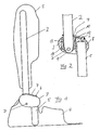
- FIG. 1 The view of Figure 1 reveals a cup-shaped, supporting lower leg part (second joint part) 1, which is open to the front, so surrounds the lower leg laterally around in the calf area.
- the lower leg part 1 with a lower leg rail (second rail) 2 is firmly connected.
- the lower leg rail 2 protrudes into a hinge part 3 and is rotatably mounted in the hinge part 3 by means of a rotation axis D.
- first rail Laterally offset forward in the hinge part 3 from below a
- first rail which is connected to a cup-shaped, upwardly and forwardly open foot part (first hinge part) 4.
- the foot rail 5 is fixed in the hinge part 3, d. H. not laterally movable, inserted.
- the rotary joint part 3 On its upper side, the rotary joint part 3 has a mushroom-shaped fastening knob 6 around which a spring elastic band 7 revolves, which on the other hand is looped around the lower leg rail 2.
- FIG. 2 The sectional view of Figure 2 illustrates that the foot rail 5 is inserted into a downwardly open, matching chamber 8 of the hinge part 3, so that the foot rail 5 is not movable in the hinge part 3.
- the lower leg rail 2 protrudes with a front, slightly tapered and rounded end 9 in an upwardly open chamber 10 of the hinge part 3.
- a replaceable inserted insert 11 made of a suitable, good sliding plastic, such as PTFE.
- the insert 11 guides the lower leg rail 2 laterally for the implementation of the rotational movement about the axis of rotation D and sets with a front stop edge 12 and a rear stop edge 13, the angle for the end positions of the rotational movement of the lower leg rail 2 relative to the hinge part 3 - and thus the foot rail 5 - fixed.
- the angular position in the standing position and the rotation angle range of the lower leg rail 2 relative to the foot rail 5 for the respective patient can be given appropriate for -Used unchanged structural parts.
- the spring-biased to train elastic band 7 the foot part 4 is pulled in the unloaded position relative to the lower leg part 1 maximum up, which corresponds to a researcherheberfunktion.
- the spring elastic band 7 is lengthened by the leverage effect of the foot part 4, so that the foot part 4 assumes a greater angle relative to the lower leg part 1 in order to allow a certain unrolling of the foot part 4 when walking relative to the lower leg part 1.
- Figure 2 illustrates that the axis of rotation D can be arranged in the lower region of the hinge part 3 and that the foot rail 5 in a projecting up to the upper portion of the hinge part 3 chamber 8 is stable, whereby the height of the foot part 4 to the rotation axis D clearly can be reduced without having to accept losses in the stability of the anchorage in the hinge part 3.
Landscapes
- Health & Medical Sciences (AREA)
- Animal Behavior & Ethology (AREA)
- Veterinary Medicine (AREA)
- Engineering & Computer Science (AREA)
- Biomedical Technology (AREA)
- Heart & Thoracic Surgery (AREA)
- Vascular Medicine (AREA)
- Orthopedic Medicine & Surgery (AREA)
- General Health & Medical Sciences (AREA)
- Life Sciences & Earth Sciences (AREA)
- Public Health (AREA)
- Nursing (AREA)
- Orthopedics, Nursing, And Contraception (AREA)
- Prostheses (AREA)
- Rehabilitation Tools (AREA)
- Acyclic And Carbocyclic Compounds In Medicinal Compositions (AREA)
Applications Claiming Priority (2)
| Application Number | Priority Date | Filing Date | Title |
|---|---|---|---|
| DE10321117 | 2003-05-09 | ||
| DE10321117A DE10321117B4 (de) | 2003-05-09 | 2003-05-09 | Gelenkorthese |
Publications (2)
| Publication Number | Publication Date |
|---|---|
| EP1479360A1 EP1479360A1 (de) | 2004-11-24 |
| EP1479360B1 true EP1479360B1 (de) | 2006-06-21 |
Family
ID=33039172
Family Applications (1)
| Application Number | Title | Priority Date | Filing Date |
|---|---|---|---|
| EP04009630A Expired - Lifetime EP1479360B1 (de) | 2003-05-09 | 2004-04-23 | Gelenkorthese |
Country Status (7)
| Country | Link |
|---|---|
| US (1) | US7413555B2 (enExample) |
| EP (1) | EP1479360B1 (enExample) |
| JP (1) | JP4565886B2 (enExample) |
| CN (1) | CN100502809C (enExample) |
| AU (1) | AU2004201844A1 (enExample) |
| CA (1) | CA2465618A1 (enExample) |
| DE (2) | DE10321117B4 (enExample) |
Families Citing this family (16)
| Publication number | Priority date | Publication date | Assignee | Title |
|---|---|---|---|---|
| DE10126622A1 (de) * | 2001-05-31 | 2002-12-05 | Gottinger Orthopaedie Technik | Unterschenkelorthese |
| US10842653B2 (en) | 2007-09-19 | 2020-11-24 | Ability Dynamics, Llc | Vacuum system for a prosthetic foot |
| US20090216167A1 (en) * | 2008-02-25 | 2009-08-27 | Nathaniel Harris | Ankle sprain reduction system |
| FR2930723B1 (fr) * | 2008-05-05 | 2010-05-28 | Gibaud | Orthese de cheville |
| EP2276431A2 (en) * | 2008-05-14 | 2011-01-26 | Össur HF | Leg support |
| US20100106065A1 (en) * | 2008-10-29 | 2010-04-29 | Ward Michael J | Orthotic Assembly for Selectively off-Loading a Weight-Bearing Joint |
| US8282588B2 (en) * | 2008-12-03 | 2012-10-09 | Ossur Hf | Orthopedic device having hybrid frame elements |
| DE102010019355B4 (de) | 2010-04-30 | 2019-03-14 | Ottobock Se & Co. Kgaa | Orthese zur Korrektur einer Beinfehlstellung |
| DE102010045164A1 (de) * | 2010-09-11 | 2012-03-15 | Otto Bock Healthcare Gmbh | Orthopädietechnische Vorrichtung und Verfahren zu deren Herstellung |
| GB201018749D0 (en) * | 2010-11-08 | 2010-12-22 | C Pro Direct Ltd | Ankle foot orthopaedic devices |
| DE102012002552A1 (de) * | 2012-02-09 | 2013-08-14 | Pohlig Gmbh | Orthese |
| USD732176S1 (en) * | 2012-05-10 | 2015-06-16 | Helmut Wagner | Orthosis |
| CN105945983B (zh) * | 2016-04-20 | 2017-11-07 | 吉林大学 | 一种用于双足步行机器人的节能减震仿生膝关节 |
| KR101845934B1 (ko) | 2016-05-03 | 2018-04-05 | 노광현 | 에어백이 구비된 깁스 대체용 환부지지장치 |
| CN108703828B (zh) * | 2018-06-04 | 2021-03-30 | 王荣涛 | 下肢牵引器 |
| WO2023249977A1 (en) * | 2022-06-21 | 2023-12-28 | Dimension Orthotics, LLC | 3d subtractive manufacturing of casts, braces, splints and other orthoses |
Family Cites Families (15)
| Publication number | Priority date | Publication date | Assignee | Title |
|---|---|---|---|---|
| DE563009C (de) * | 1932-10-31 | Herm R K Wennig | Beinstuetzschiene | |
| GB720512A (en) * | 1952-07-22 | 1954-12-22 | James Guest | Improvements in ankle and knee supports for personal wear and for artificial limbs |
| GB750512A (en) | 1953-07-25 | 1956-06-20 | Wingrove & Rogers Ltd | Improvements in or relating to variable condensers or capacitors as used in radio and other electronic apparatus |
| US4237873A (en) * | 1978-12-11 | 1980-12-09 | Hoyt Laurance J Sr | Cerebral palsy arm and hand brace |
| DE2918864A1 (de) * | 1979-05-10 | 1980-11-20 | Teufel Wilh Jul Fa | Knieorthese |
| US4508111A (en) * | 1981-07-23 | 1985-04-02 | Dynasplint Systems, Inc. | Adjustable splint |
| US4771768A (en) * | 1986-12-16 | 1988-09-20 | United States Manufacturing Company | Controlled motion ankle fracture walker |
| US4777941A (en) * | 1987-07-29 | 1988-10-18 | Borig Donald A | Orthopedic knee prosthesis and hinge |
| GB2216423B (en) * | 1988-03-04 | 1992-10-28 | Blatchford & Sons Ltd | Lower limb prosthesis |
| GB8918523D0 (en) * | 1989-08-14 | 1989-09-20 | Protectair Ltd | Improvements to bi-pivotal orthopaedic hinges |
| US5060640A (en) * | 1990-03-14 | 1991-10-29 | Becker Orthopedic Appliance Company | Knee brace |
| JPH0817789B2 (ja) * | 1993-01-29 | 1996-02-28 | 株式会社今仙技術研究所 | カバーの破損を防止する内骨格義足用膝継手 |
| US5857989A (en) * | 1997-11-24 | 1999-01-12 | Smith, Iii; Kirby | Dynamic orthopedic knee brace assembly |
| US6500138B1 (en) * | 2000-04-07 | 2002-12-31 | Mayo Foundation For Medical Education And Research | Electromechanical joint control device with wrap spring clutch |
| US6752774B2 (en) * | 2001-06-08 | 2004-06-22 | Townsend Design | Tension assisted ankle joint and orthotic limb braces incorporating same |
-
2003
- 2003-05-09 DE DE10321117A patent/DE10321117B4/de not_active Expired - Fee Related
-
2004
- 2004-04-23 DE DE502004000804T patent/DE502004000804D1/de not_active Expired - Lifetime
- 2004-04-23 EP EP04009630A patent/EP1479360B1/de not_active Expired - Lifetime
- 2004-04-30 CA CA002465618A patent/CA2465618A1/en not_active Abandoned
- 2004-05-04 AU AU2004201844A patent/AU2004201844A1/en not_active Abandoned
- 2004-05-06 US US10/839,699 patent/US7413555B2/en not_active Expired - Fee Related
- 2004-05-07 JP JP2004138399A patent/JP4565886B2/ja not_active Expired - Fee Related
- 2004-05-09 CN CNB2004100422809A patent/CN100502809C/zh not_active Expired - Fee Related
Also Published As
| Publication number | Publication date |
|---|---|
| DE10321117B4 (de) | 2006-09-21 |
| JP2004329945A (ja) | 2004-11-25 |
| CN100502809C (zh) | 2009-06-24 |
| JP4565886B2 (ja) | 2010-10-20 |
| CN1572262A (zh) | 2005-02-02 |
| EP1479360A1 (de) | 2004-11-24 |
| US20040260220A1 (en) | 2004-12-23 |
| US7413555B2 (en) | 2008-08-19 |
| DE502004000804D1 (de) | 2006-08-03 |
| CA2465618A1 (en) | 2004-11-09 |
| AU2004201844A1 (en) | 2004-11-25 |
| DE10321117A1 (de) | 2004-12-16 |
Similar Documents
| Publication | Publication Date | Title |
|---|---|---|
| EP1479360B1 (de) | Gelenkorthese | |
| EP1568337B1 (de) | Orthese zur Korrektur der Stellung eines Körpergelenks | |
| DE2527864C3 (de) | Gelenkendoprothese für ein Handgelenk | |
| EP2563300B1 (de) | Orthese zur korrektur einer beinfehlstellung | |
| DE10240121A1 (de) | Orthopädische Vorrichtung zur Korrektur von Zehenfehlstellungen | |
| WO2019122364A1 (de) | Hartrahmen mit verschwenkbarer brücke | |
| EP3019126A1 (de) | Orthesengelenk | |
| DE202011004130U1 (de) | Orthesengelenk mit zwei Funktionsmitteln zum Bilden eines federnden Dorsalanschlags und eines federnden Plantaranschlags | |
| EP2524672B1 (de) | Gelenk für Kniegelenks-Orthesen, -Prothesen bzw. -Stützen | |
| EP3285698B1 (de) | Führungsgelenk für eine gelenksorthese | |
| DE3924428C2 (de) | Stütze für den Sprunggelenkbereich mit einem als stiefelartigen Teilschuh ausgebildeten Stützteil | |
| DE102016108049A1 (de) | Orthese | |
| WO2008040291A1 (de) | Prothese mit einem schaft zur aufnahme eines amputationsstumpfes | |
| EP3448329A1 (de) | Orthesengelenk, baukastensystem zur bildung eines orthesengelenkes und verwendung dessen | |
| EP4119108A1 (de) | Gelenkanordnung für eine orthese eines extremitätengelenks, set zum konfigurieren der gelenkanordnung und orthese mit einer derartigen gelenkanordnung | |
| EP2626046A1 (de) | Orthese | |
| WO2017133731A1 (de) | Arbeitsmittel zur stabilisierung von knochenbrüchen | |
| DE202018103647U1 (de) | Handgelenkorthese | |
| EP3426200B1 (de) | Flexibles stützelement für eine orthese | |
| EP1186279A1 (de) | Gelenkorthese mit bewegungsinduzierter Entriegelung | |
| DE19638683A1 (de) | Knöchelorthese | |
| EP3922221B1 (de) | Sprunggelenkorthese | |
| EP4212134A1 (de) | Fussgelenk-orthese | |
| EP0897273B1 (de) | Orthopädische einlage | |
| DE10338128A1 (de) | Unterschenkelorthese |
Legal Events
| Date | Code | Title | Description |
|---|---|---|---|
| PUAI | Public reference made under article 153(3) epc to a published international application that has entered the european phase |
Free format text: ORIGINAL CODE: 0009012 |
|
| AK | Designated contracting states |
Kind code of ref document: A1 Designated state(s): AT BE BG CH CY CZ DE DK EE ES FI FR GB GR HU IE IT LI LU MC NL PL PT RO SE SI SK TR |
|
| AX | Request for extension of the european patent |
Extension state: AL HR LT LV MK |
|
| 17P | Request for examination filed |
Effective date: 20041023 |
|
| GRAP | Despatch of communication of intention to grant a patent |
Free format text: ORIGINAL CODE: EPIDOSNIGR1 |
|
| GRAS | Grant fee paid |
Free format text: ORIGINAL CODE: EPIDOSNIGR3 |
|
| AKX | Designation fees paid |
Designated state(s): DE FR GB IT SE |
|
| RIN1 | Information on inventor provided before grant (corrected) |
Inventor name: WAGNER, HELMUT Inventor name: VON ASCHEBERG, ALEXANDER |
|
| GRAA | (expected) grant |
Free format text: ORIGINAL CODE: 0009210 |
|
| AK | Designated contracting states |
Kind code of ref document: B1 Designated state(s): DE FR GB IT SE |
|
| PG25 | Lapsed in a contracting state [announced via postgrant information from national office to epo] |
Ref country code: IT Free format text: LAPSE BECAUSE OF FAILURE TO SUBMIT A TRANSLATION OF THE DESCRIPTION OR TO PAY THE FEE WITHIN THE PRESCRIBED TIME-LIMIT;WARNING: LAPSES OF ITALIAN PATENTS WITH EFFECTIVE DATE BEFORE 2007 MAY HAVE OCCURRED AT ANY TIME BEFORE 2007. THE CORRECT EFFECTIVE DATE MAY BE DIFFERENT FROM THE ONE RECORDED. Effective date: 20060621 |
|
| REG | Reference to a national code |
Ref country code: GB Ref legal event code: FG4D Free format text: NOT ENGLISH |
|
| REG | Reference to a national code |
Ref country code: SE Ref legal event code: TRGR |
|
| REF | Corresponds to: |
Ref document number: 502004000804 Country of ref document: DE Date of ref document: 20060803 Kind code of ref document: P |
|
| GBT | Gb: translation of ep patent filed (gb section 77(6)(a)/1977) |
Effective date: 20060726 |
|
| ET | Fr: translation filed | ||
| PLBE | No opposition filed within time limit |
Free format text: ORIGINAL CODE: 0009261 |
|
| STAA | Information on the status of an ep patent application or granted ep patent |
Free format text: STATUS: NO OPPOSITION FILED WITHIN TIME LIMIT |
|
| 26N | No opposition filed |
Effective date: 20070322 |
|
| PGRI | Patent reinstated in contracting state [announced from national office to epo] |
Ref country code: IT Effective date: 20080601 |
|
| REG | Reference to a national code |
Ref country code: FR Ref legal event code: PLFP Year of fee payment: 12 |
|
| PGFP | Annual fee paid to national office [announced via postgrant information from national office to epo] |
Ref country code: GB Payment date: 20150423 Year of fee payment: 12 Ref country code: SE Payment date: 20150423 Year of fee payment: 12 |
|
| REG | Reference to a national code |
Ref country code: DE Ref legal event code: R082 Ref document number: 502004000804 Country of ref document: DE Representative=s name: GRAMM, LINS & PARTNER PATENT- UND RECHTSANWAEL, DE |
|
| PGFP | Annual fee paid to national office [announced via postgrant information from national office to epo] |
Ref country code: IT Payment date: 20150427 Year of fee payment: 12 Ref country code: FR Payment date: 20150422 Year of fee payment: 12 |
|
| REG | Reference to a national code |
Ref country code: SE Ref legal event code: EUG |
|
| GBPC | Gb: european patent ceased through non-payment of renewal fee |
Effective date: 20160423 |
|
| REG | Reference to a national code |
Ref country code: FR Ref legal event code: ST Effective date: 20161230 |
|
| PG25 | Lapsed in a contracting state [announced via postgrant information from national office to epo] |
Ref country code: GB Free format text: LAPSE BECAUSE OF NON-PAYMENT OF DUE FEES Effective date: 20160423 Ref country code: FR Free format text: LAPSE BECAUSE OF NON-PAYMENT OF DUE FEES Effective date: 20160502 |
|
| PG25 | Lapsed in a contracting state [announced via postgrant information from national office to epo] |
Ref country code: IT Free format text: LAPSE BECAUSE OF FAILURE TO SUBMIT A TRANSLATION OF THE DESCRIPTION OR TO PAY THE FEE WITHIN THE PRESCRIBED TIME-LIMIT Effective date: 20160423 Ref country code: SE Free format text: LAPSE BECAUSE OF NON-PAYMENT OF DUE FEES Effective date: 20160424 |
|
| PGFP | Annual fee paid to national office [announced via postgrant information from national office to epo] |
Ref country code: DE Payment date: 20170425 Year of fee payment: 14 |
|
| REG | Reference to a national code |
Ref country code: DE Ref legal event code: R119 Ref document number: 502004000804 Country of ref document: DE |
|
| PG25 | Lapsed in a contracting state [announced via postgrant information from national office to epo] |
Ref country code: DE Free format text: LAPSE BECAUSE OF NON-PAYMENT OF DUE FEES Effective date: 20181101 |