EP1478206B1 - Tonwiedergabevorrichtung - Google Patents
Tonwiedergabevorrichtung Download PDFInfo
- Publication number
- EP1478206B1 EP1478206B1 EP04010364.0A EP04010364A EP1478206B1 EP 1478206 B1 EP1478206 B1 EP 1478206B1 EP 04010364 A EP04010364 A EP 04010364A EP 1478206 B1 EP1478206 B1 EP 1478206B1
- Authority
- EP
- European Patent Office
- Prior art keywords
- sound
- reproducing apparatus
- signal
- board
- sound reproducing
- Prior art date
- Legal status (The legal status is an assumption and is not a legal conclusion. Google has not performed a legal analysis and makes no representation as to the accuracy of the status listed.)
- Expired - Lifetime
Links
- 239000000463 material Substances 0.000 claims description 13
- 230000005236 sound signal Effects 0.000 claims description 5
- 238000010586 diagram Methods 0.000 description 16
- 230000003321 amplification Effects 0.000 description 15
- 238000003199 nucleic acid amplification method Methods 0.000 description 15
- 125000006850 spacer group Chemical group 0.000 description 12
- 238000001514 detection method Methods 0.000 description 9
- 230000009467 reduction Effects 0.000 description 9
- 238000000034 method Methods 0.000 description 6
- 230000000694 effects Effects 0.000 description 5
- 230000015556 catabolic process Effects 0.000 description 4
- 238000006731 degradation reaction Methods 0.000 description 4
- 230000006870 function Effects 0.000 description 4
- 238000007789 sealing Methods 0.000 description 4
- 230000003287 optical effect Effects 0.000 description 3
- 229920000139 polyethylene terephthalate Polymers 0.000 description 3
- 239000005020 polyethylene terephthalate Substances 0.000 description 3
- 238000002834 transmittance Methods 0.000 description 3
- 239000004925 Acrylic resin Substances 0.000 description 2
- 229920000178 Acrylic resin Polymers 0.000 description 2
- NIXOWILDQLNWCW-UHFFFAOYSA-N acrylic acid group Chemical group C(C=C)(=O)O NIXOWILDQLNWCW-UHFFFAOYSA-N 0.000 description 2
- 230000002411 adverse Effects 0.000 description 2
- 230000008859 change Effects 0.000 description 2
- 239000011521 glass Substances 0.000 description 2
- 239000004973 liquid crystal related substance Substances 0.000 description 2
- 230000000644 propagated effect Effects 0.000 description 2
- 230000002159 abnormal effect Effects 0.000 description 1
- 230000009471 action Effects 0.000 description 1
- 239000000853 adhesive Substances 0.000 description 1
- 230000015572 biosynthetic process Effects 0.000 description 1
- 230000000903 blocking effect Effects 0.000 description 1
- 230000004048 modification Effects 0.000 description 1
- 238000012986 modification Methods 0.000 description 1
- 229920003217 poly(methylsilsesquioxane) Polymers 0.000 description 1
- -1 polyethylene terephthalate Polymers 0.000 description 1
- 230000008569 process Effects 0.000 description 1
- 239000000758 substrate Substances 0.000 description 1
- 239000000725 suspension Substances 0.000 description 1
- 239000012780 transparent material Substances 0.000 description 1
Images


Classifications
-
- H—ELECTRICITY
- H04—ELECTRIC COMMUNICATION TECHNIQUE
- H04M—TELEPHONIC COMMUNICATION
- H04M1/00—Substation equipment, e.g. for use by subscribers
- H04M1/02—Constructional features of telephone sets
- H04M1/03—Constructional features of telephone transmitters or receivers, e.g. telephone hand-sets
-
- C—CHEMISTRY; METALLURGY
- C10—PETROLEUM, GAS OR COKE INDUSTRIES; TECHNICAL GASES CONTAINING CARBON MONOXIDE; FUELS; LUBRICANTS; PEAT
- C10L—FUELS NOT OTHERWISE PROVIDED FOR; NATURAL GAS; SYNTHETIC NATURAL GAS OBTAINED BY PROCESSES NOT COVERED BY SUBCLASSES C10G, C10K; LIQUEFIED PETROLEUM GAS; ADDING MATERIALS TO FUELS OR FIRES TO REDUCE SMOKE OR UNDESIRABLE DEPOSITS OR TO FACILITATE SOOT REMOVAL; FIRELIGHTERS
- C10L5/00—Solid fuels
- C10L5/02—Solid fuels such as briquettes consisting mainly of carbonaceous materials of mineral or non-mineral origin
- C10L5/34—Other details of the shaped fuels, e.g. briquettes
- C10L5/36—Shape
-
- B—PERFORMING OPERATIONS; TRANSPORTING
- B65—CONVEYING; PACKING; STORING; HANDLING THIN OR FILAMENTARY MATERIAL
- B65D—CONTAINERS FOR STORAGE OR TRANSPORT OF ARTICLES OR MATERIALS, e.g. BAGS, BARRELS, BOTTLES, BOXES, CANS, CARTONS, CRATES, DRUMS, JARS, TANKS, HOPPERS, FORWARDING CONTAINERS; ACCESSORIES, CLOSURES, OR FITTINGS THEREFOR; PACKAGING ELEMENTS; PACKAGES
- B65D71/00—Bundles of articles held together by packaging elements for convenience of storage or transport, e.g. portable segregating carrier for plural receptacles such as beer cans or pop bottles; Bales of material
-
- H—ELECTRICITY
- H04—ELECTRIC COMMUNICATION TECHNIQUE
- H04R—LOUDSPEAKERS, MICROPHONES, GRAMOPHONE PICK-UPS OR LIKE ACOUSTIC ELECTROMECHANICAL TRANSDUCERS; DEAF-AID SETS; PUBLIC ADDRESS SYSTEMS
- H04R1/00—Details of transducers, loudspeakers or microphones
- H04R1/02—Casings; Cabinets ; Supports therefor; Mountings therein
- H04R1/025—Arrangements for fixing loudspeaker transducers, e.g. in a box, furniture
-
- H—ELECTRICITY
- H04—ELECTRIC COMMUNICATION TECHNIQUE
- H04R—LOUDSPEAKERS, MICROPHONES, GRAMOPHONE PICK-UPS OR LIKE ACOUSTIC ELECTROMECHANICAL TRANSDUCERS; DEAF-AID SETS; PUBLIC ADDRESS SYSTEMS
- H04R2499/00—Aspects covered by H04R or H04S not otherwise provided for in their subgroups
- H04R2499/10—General applications
- H04R2499/11—Transducers incorporated or for use in hand-held devices, e.g. mobile phones, PDA's, camera's
-
- H—ELECTRICITY
- H04—ELECTRIC COMMUNICATION TECHNIQUE
- H04R—LOUDSPEAKERS, MICROPHONES, GRAMOPHONE PICK-UPS OR LIKE ACOUSTIC ELECTROMECHANICAL TRANSDUCERS; DEAF-AID SETS; PUBLIC ADDRESS SYSTEMS
- H04R2499/00—Aspects covered by H04R or H04S not otherwise provided for in their subgroups
- H04R2499/10—General applications
- H04R2499/15—Transducers incorporated in visual displaying devices, e.g. televisions, computer displays, laptops
Definitions
- the present invention relates to a sound reproducing apparatus, and more particularly to a sound reproducing apparatus having a display means and acoustically driving a transparent diaphragm panel.
- FIG. 11 is an external perspective view of a television set having a conventional sound reproducing apparatus.
- the television set includes a cabinet 1, a cathode ray tube 2, a front panel 3, a driver 4, and sound slits 5.
- the front panel 3 is mounted in front of the cathode ray tube 2.
- the front panel 3 is composed of a material with high optical transmittance, such as glass or transparent acrylic.
- the driver 4 is an electromagnetic-type speaker and directly connected to the back of the front panel 3.
- a plurality of sound slits 5 (four sound slits in FIG. 11 ) are provided around the perimeter of the cathode ray tube 2.
- the television set shown in FIG. 11 reproduces sound by a method for directly driving the transparent diaphragm panel by means of the driver.
- the driver 4 causes vibration. Since the driver 4 is directly mounted to the front panel 3, the vibration caused by the driver 4 is mechanically transmitted to the front panel 3, causing the front panel 3 to vibrate. Specifically, if the electrical signal applied to the driver 4 is an audio signal, sound is reproduced from the front panel 3 mounted in front of the cathode ray tube 2. Since the front panel 3 is composed of a material with high optical transmittance, the front panel 3 does not degrade an image reproduced on the cathode ray tube 2. In this manner, the television set shown in FIG. 11 can simultaneously reproduce images and sounds.
- the sound slits 5 are provided. Specifically, sound coming from the back of the front panel 3 passes through the sound slits 5 and then is emitted into the cabinet 1. Thus, an increase in the air pressure of the space can be avoided by means of the sound slits 5.
- FIG. 11 While the sound reproducing apparatus shown in FIG. 11 is used as a television set, there also exists a sound reproducing apparatus which can be used as a mobile telephone. Such a sound reproducing apparatus reproduces sound by causing an outer case which is directly mounted to the mobile telephone to vibrate by means of the driver. This sound reproducing apparatus will be described below with reference to FIG. 12 .
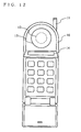
- FIG. 12 is an external view of a mobile telephone having a conventional sound reproducing apparatus.
- the mobile telephone includes an outer case 10, an antenna 11, a soundboard 12, a driver 13, and a display screen 14.
- the soundboard 12 is formed on the upper front of the outer case 10 such that the perimeter thereof is thin (not shown).
- the driver 13 is directly mounted to the back of the soundboard 12.
- the display screen 14 is provided on the front of the outer case 10 and below the soundboard 12.
- the operation of the sound reproducing apparatus shown in FIG. 12 will be described below.
- the driver 13 causes vibration.
- the vibration caused by the driver 13 is directly transmitted to the soundboard 12 formed on the outer case 10, causing the soundboard 12 to vibrate, thereby reproducing sound.
- the driver 4 is mounted in a location around the perimeter of the front panel 3 so as not to block the display screen of the cathode ray tube 2.
- the driver 4 is mounted in a location around the perimeter of the front panel 3, so as not to block the display screen of the cathode ray tube 2.
- the front panel 3 acts not only as a diaphragm panel for emitting sound but also as a protection panel for protecting the cathode ray tube 2, the front panel 3 requires moderate strength. Therefore, the front panel 3 needs to be configured to have a certain thickness. This increases the weight of the front panel 3, reducing the vibration of the front panel 3 brought about by the driver 4, resulting in a reduction in reproduced sound pressure. Thus, in the sound reproducing apparatus shown in FIG. 11 , the efficiency of the reproduced sound pressure with respect to the driver is very low as compared with that of conventional speakers.
- the sound reproducing apparatus shown in FIG. 12 cannot be appropriately applied to recent mobile telephones in which larger display screens are highly demanded. Specifically, in the sound reproducing apparatus shown in FIG. 12 , the display screen 14 and the soundboard 12 are provided in different locations, which hinders the formation of a larger display screen 14 due to the presence of the soundboard 12. In addition, since the display screen 14 is provided in a different location from where sound is reproduced, the user cannot get the sense that the sound is being reproduced from the display screen 14.
- GB 2 343 811 A describes a sound reproducing apparatus comprising a display unit, a diaphragm panel composed of a material which transmits visible light and an electroacoustic transducer being disposed opposite the display unit.
- an object of the present invention is to provide a sound reproducing apparatus capable of reproducing high quality sound while giving the user the sense that the sound is being reproduced from a display means.
- the present invention has the following features to attain the object mentioned above.
- the present invention is directed to a sound reproducing apparatus comprising a display unit, a board, a diaphragm panel, and at least one electroacoustic transducer.
- the display unit displays an image on a display surface.
- the display unit includes, for example, a display device such as a liquid crystal display device, a picture in which an image is illustrated, and a photograph.
- the board is composed of a material which transmits visible light and arranged such that a first space is provided between the display surface of the display unit and the board.
- the diaphragm panel is composed of a material which transmits visible light and arranged on the opposite side of the board from the display unit such that a second space is provided between the board and the diaphragm panel.
- the electroacoustic transducer emits sound into the second space.
- the board has a sound hole, and the electroacoustic transducer emits sound into the second space through the sound hole.
- the sound reproducing apparatus may further comprise a case having an opening which is covered by the diaphragm panel.
- the case contains therein the board, the display unit, and the electroacoustic transducer.
- the diaphragm panel may be composed of a touch panel.
- the sound reproducing apparatus may further comprise: an antenna for receiving a signal; and a signal processing unit.
- the signal processing unit performs predetermined signal processing on the signal received by the antenna and inputs the processed signal to the electroacoustic transducer.
- a number of the at lease one electroacoustic transducer may be two.
- the signal processing unit inputs to one of the two electroacoustic transducers a signal received by the antenna if the signal includes an incoming speech sound signal, and inputs to the other one of the two electroacoustic transducers a signal received by the antenna if the signal includes a signal other than an incoming speech sound signal.
- the diaphragm panel is acoustically driven by the sound emitted into the second space from the electroacoustic transducer.
- the mounting position of the electroacoustic transducer does not adversely affect sound reproduction.
- a reduction in sound quality caused by the mounting position of the electroacoustic transducer will not occur.
- the electroacoustic transducer since the electroacoustic transducer can be freely arranged, the electroacoustic transducer will not block the display unit and the user can get the sense that the sound is being reproduced from the display unit.
- FIGS. 1A and 1B are diagrams illustrating a configuration of the sound reproducing apparatus according to the first example.
- FIG. 1A is a plan view of the sound reproducing apparatus
- FIG. 1B is a cross-sectional view of the sound reproducing apparatus taken along a line A-B of FIG. 1A .
- the sound reproducing apparatus according to the first example can be implemented as a mobile terminal apparatus such as a mobile telephone or PDA.
- the sound reproducing apparatus includes an outer case 20, a display device 21, a board 22, a diaphragm panel 23, a spacer 24, and an electroacoustic transducer 26.
- the display device 21 may be a liquid crystal display device, for example.
- the board 22 and the diaphragm panel 23 are composed of materials which transmit visible light.
- the board 22 is composed of glass or acrylic resin, for example.
- the diaphragm panel 23 is composed of acrylic resin or PET (polyethylene terephthalate), for example.
- the outer case 20 has an opening, the size of which is almost the same as the size of the display device 21.
- the display device 21 is provided so as to cover the opening. Thus, the perimeter of the display device 21 is connected to the opening.
- the display device 21 is arranged inside the outer case 20.
- the board 22 is provided to the outer case 20 on the outside (on the left side in FIG. 1B ) of the display device 21.
- a first space is provided between the display device 21 and the board 22.
- the board 22 is connected to the outer case 20 at its perimeter.
- the diaphragm panel 23 is provided to the outer case 20 on the outside (on the left side in FIG. 1B ) of the board 22.
- the diaphragm panel 23 is placed on the opposite side of the board 22 from the display device 21.
- the board 22 and the diaphragm panel 23 are adhered to each other at their perimeters by means of the spacer 24, thereby providing a second space between the board 22 and the diaphragm panel 23.
- a sound hole 27 is provided in the board 22 and the outer case 20.
- the electroacoustic transducer 26 is placed on the opposite side of the board 22 from the second space 25.
- the electroacoustic transducer 26 is connected to the outer case 20 so as to cover the sound hole 27.
- the electroacoustic transducer 26 may be directly connected to the board 22.
- the electroacoustic transducer 26 is arranged inside the outer case 20, as is the display device 21.
- FIG. 2 is a cross-sectional view of the electroacoustic transducer 26 shown in FIGS. 1A and 1B .
- the electroacoustic transducer 26 includes a pot type yoke 40, a magnet 41, a plate 42, a voice coil 44, a diaphragm 45, and a frame 46.
- the frame 46 is connected to the perimeter of a sound hole 27 of the outer case 20 so as to cover the sound hole 27.
- the yoke 40 is adhered to the center of the frame 46 at its outer underside (the underside surface in FIG. 2 ).
- the magnet 41 is provided at the center of the yoke 40.
- the plate 42 is arranged on the top surface of the magnet 41.
- the yoke 40 and the plate 42 are arranged such that amagnetic air gap 43 is provided between the inner surface of the yoke 40 and the outer surface of the plate 42.
- the diaphragm 45 is adhered to the frame 46 at its perimeter.
- the voice coil 44 is adhered to the diaphragm 45 so as to be inserted in the magnetic air gap 43.
- the mounting position of the electroacoustic transducer 26, which serves as a driver does not adversely affect the quality of reproduced sound. Accordingly, it is possible to freely select the mounting position of the electroacoustic transducer 26 and to prevent degradation of the quality of reproduced sound.
- the diaphragm panel 23 vibrates in such a manner that the diaphragm panel 23 itself bends.
- the spacer 24 is composed of a suspension made of an elastic body
- the diaphragm panel 23 vibrates in such a manner that the diaphragm panel 23 itself creates a piston action.
- the diaphragm panel 23 may be caused to vibrate in either of the above two manners.
- the sound pressure equivalent to that applied to the diaphragm panel 23 is also applied to the board 22.
- the force to cause the board 22 to vibrate is created by the sound pressure. If the board 22 vibrates, the energy of the sound emitted into the second space 25 is distributed to the diaphragm panel 23 and the board 22. Therefore, in this case, the sound pressure level reproduced from the diaphragm panel 23 is lower than that obtained when the board 22 does not vibrate.
- the energy to cause the diaphragm panel 23 to vibrate is taken away by vibration of the board 22, resulting in a reduction in vibration of the diaphragm panel 23. Therefore, it is necessary to prevent the board 22 from vibrating by the sound pressure in the second space 25.
- the thickness of the board 22 may be increased so as to provide a sufficient strength to the board 22.
- the increase in the thickness of the board 22 may, however, lead to an increase in the thickness of the sound reproducing apparatus, which is unfavorable, especially for mobile terminal apparatuses that seek a reduction in their size and weight.
- the board 22 may be closely stuck to the display screen of the display device 21 with an adhesive agent. However, if the board 22 and the display screen are bonded together, the optical transmittance may be reduced by a bonding layer, resulting in degradation in the image quality of the display screen. For this reason, the first space 28, as shown in FIG. 1B , is required between the board 22 and the display screen.
- the vibration of the board 22 is suppressed by sealing the first space 28. That is, the vibration of the board 22 is suppressed by the acoustic stiffness of the air in the first space 28.
- the vibration of the board 22 can be suppressed. In this manner, a reduction in the sound pressure of the diaphragm panel 23 caused by vibration of the board 22 can be prevented.
- the board 22 and the diaphragm panel 23 are composed of transparent materials, the user can see the display screen of the display device 21 from the outside of the sound reproducing apparatus.
- the electroacoustic transducer 26 is arranged on the lateral side of the display device 21, the electroacoustic transducer 26 does not block the display screen.
- the sound reproducing apparatus can give the user the sense that the sound is being reproduced from the display screen, while preventing the degradation of the quality of reproduced sound.
- a reduction in the pressure of reproduced sound can be prevented.
- the board can be made thinner, achieving a reduction in the thickness of the sound reproducing apparatus.
- three components, a board 22; a diaphragm panel 23; and a spacer 24, can be produced as one unit. Specifically, the three components are assembled while producing the main unit separately from the three components, and then an assemblage of the three components is mounted to the main unit. This facilitates the production of a sound reproducing apparatus.
- the display screen of the display device is covered by the board 22 and the diaphragm panel 23, the display screen can be more securely protected as compared to the case without the board 22.
- the outer shape of the electroacoustic transducer 26 is circular; however, the shape may be elliptical or rectangular, by which the display screen of the display device 21 can be made larger.
- FIG. 3 is a plane view illustrating a mobile telephone according to the second example which is partially cut out.
- FIG. 4 is a block diagram illustrating the mobile telephone according to the second example.
- a mobile telephone 100 includes an outer case 101, an antenna 102, a display device 103, a board 104, a diaphragm panel 105, a spacer 106, an electroacoustic transducer 110, a signal processing section 111, and a signal amplification section 112.
- the outer case 101 contains electrical circuits and the like of the mobile telephone 100.
- the antenna 102 is mounted to the outer case 101.
- the diaphragm panel 105 is partially cut out.
- the signal processing section 111 is connected to the antenna 102 and to the signal amplification section 112.
- the signal amplification section 112 is connected to the signal processing section 111 and to the electroacoustic transducer 110. Note that the configuration of the sound reproducing apparatus 113 shown by the dotted line in FIG. 4 is the same as that of the first example except for the outer shape of the outer case 101.
- a signal received by the antenna 102 is inputted to the signal processing section 111.
- an incoming speech signal indicating an incoming speech sound which is a speaking voice of a transmitter is received by the antenna 102.
- the signal processing section 111 performs predetermined signal processing on the signal inputted from the antenna 102.
- the processing includes, for example, the process of extracting an incoming speech signal from the inputted signal.
- the signal which has undergone signal processing is amplified by the signal amplification section 112 and then applied to the electroacoustic transducer 110.
- the diaphragm panel 105 operates as a receiver which serves as a speaker for speech sound reproduction. Since substantially the entire surface of the diaphragm panel 105 is caused to vibrate by the sound pressure in a second space 109, a receiver is realized which provides a wide hearing range, i.e. , the user can hear speech sounds with their ear being held to any point of the diaphragm panel 105.
- FIG. 5 is a diagram illustrating a measuring device for measuring the receiver characteristics of the sound reproducing apparatus according to the second example.
- the measuring device includes a measuring cover 120, an acoustic coupler 122, and a measuring microphone 123.
- the measuring cover 120 is mounted to a diaphragm panel 105 so as to provide a sealed space 121 between the measuring cover 120 and the diaphragm panel 105.
- the acoustic coupler 122 has acoustic characteristics of the auditory stimuli which conform to International Standard IEC (International Electrotechnical Commission).
- IEC International Electrotechnical Commission
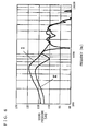
- FIG. 6 is a diagram showing the results obtained by measuring the sound pressure frequency characteristics of a sound reproducing apparatus, by means of the measuring device shown in FIG. 5 .
- the vertical axis represents the pressure of sound emitted from a sound reproducing apparatus
- the horizontal axis represents the frequency of the sound.
- the electroacoustic transducer 110 is an electrodynamic-type speaker with a diameter of 10 mm
- the board 104 is composed of a transparent acrylic material with a material thickness of 0.65 mm
- the diaphragm panel 105 is composed of a transparent PET material with a length of 60 mm, a width of 40 mm, and a thickness of 0.190 mm.
- the air gap width of the first space 108 is 0.5 mm
- the air gap width of the second space 109 is 0.2 mm
- the air gap width of the sealed space 121 provided in front of the diaphragm panel 105 is 0.2 mm.
- the "I” shown in FIG. 6 indicates the sound pressure frequency characteristics obtained when the first space 108 is present at the back of the board 104.
- the “II” shown in FIG. 6 indicates the sound pressure frequency characteristics obtained when the first space 108 is not present at the back of the board 104.
- the board 104 is caused to vibrate by the pressure of sound emitted into the second space 109 from the electroacoustic transducer 110.
- the acoustic energy to cause the diaphragm panel 105 to vibrate is consumed, reducing the pressure of the sound emitted from the diaphragm panel 105.
- the acoustic stiffness of the air in the first space 108 is high, and thus the vibration of the board 104 is suppressed. That is, in this case, although the material thickness of the board 104 is as thin as 0.65 mm, the board 104 functions as if it were a rigid body. Accordingly, the sound pressure level is higher in the frequency bands at or below 1 kHz than that in the case where the first space 108 is absent, by about 3 to 10 dB. As can be seen, by providing the first space 108, it is possible to significantly improve the loss of an acoustic energy caused by the board 104.
- the mobile telephone 100 can also obtain the same advantageous effects as those obtained by the first example.
- the signal applied to the electroacoustic transducer 110 is an incoming speech signal.
- a ringing signal indicating an incoming call, a music signal, or a signal indicating a sound effect of a game may be received by the antenna 102, and the received signal may be applied to the electroacoustic transducer 110.
- the diaphragm panel 105 functions as a loudspeaker for reproducing a ringing sound, music, or a sound effect of a game.
- the mobile telephone 100 functions as a videophone
- the person the user is talking to is displayed on the display screen and their speaking voice is reproduced by the diaphragm panel 105.
- the driver is directly mounted to the outer case
- to reproduce sound with a sufficient sound pressure the major part of the outer case needs to be used as a vibration surface. This limits the space for a display device, making it impossible to employ a large display screen (see FIG. 12 ).
- amethodof acoustically driving the diaphragm panel 105 is employed, and therefore it is possible to provide a mobile telephone having a large display screen which conventional mobile telephones have been unable to employ.
- a sound reproducing apparatus will be described below with reference to the drawings.
- the sound reproducing apparatus according to the third example is also implemented as a mobile terminal apparatus, as with the first example.
- the sound reproducing apparatus according to the third example has two electroacoustic transducers.
- FIGS. 7A and 7B are diagrams illustrating the sound reproducing apparatus according to the third example.
- FIG. 7A is a plane view illustrating the sound reproducing apparatus
- FIG. 7B is a cross-sectional view of the sound reproducing apparatus taken along a line C-D of FIG. 7A .
- the sound reproducing apparatus includes an outer case 130, a display device 131, a board 132, a diaphragm panel 134, a spacer 140, a first electroacoustic transducer 136, and a second electroacoustic transducer 138.
- a first sound hole 137 and a second sound hole 139 are each provided in the board 132 and the outer case 130.
- the first and second electroacoustic transducers 136 and 138 are arranged on the opposite side of the board 132 from the second space 135.
- the first electroacoustic transducer 136 is connected to the outer case 130 so as to cover the first sound hole 137.
- the second electroacoustic transducer 138 is connected to the outer case 130 so as to cover the second sound hole 139.
- the configuration is the same as that of the first example except for the first and second electroacoustic transducers 136 and 138 and the first and second sound holes 137 and 139.
- the operating principles that the diaphragm panel 134 is caused to vibrate by applying an electrical signal to at least one of the first and second electroacoustic transducers 136 and 138 are the same as those of the first example.
- the mobile terminal apparatus according to the third example may be used as a mobile telephone such as the one described in the second example.
- FIG. 8 is a block diagram illustrating the mobile terminal apparatus according to the third example which is used as a mobile telephone.
- the mobile telephone includes a sound reproducing apparatus 150, an antenna 151, a signal processing section 152, a first signal amplification section 153, and a second signal amplification section 154.
- the sound reproducing apparatus 150 is a sound reproducing apparatus shown in FIG. 7B .
- the signal processing section 152 is connected to the antenna 151 and to the first and second signal amplification sections 153 and 154.
- the first signal amplification section 153 is connected to the first electroacoustic transducer 136.
- the second signal amplification section 154 is connected to the second electroacoustic transducer 138.
- the antenna 151 receives a signal sent from the base station of the mobile telephone.
- the signal includes a ringing signal, an incoming speech signal indicating an incoming speech sound, an acoustic signal such as music, or an image signal such as amoving image or textual information.
- the signal received by the antenna 151 undergoes signal processing in the signal processing section 152, and then the processed signal is inputted to either the first signal amplification section 153 or the second signal amplification section 154.
- the signal processing section 152 performs signal processing on the incoming speech signal and outputs the processed incoming speech signal to the first signal amplification 153.
- the incoming speech signal is then amplified by the first signal amplification section 153, and then the amplified signal is applied to the first electroacoustic transducer 136.
- the diaphragm panel 134 operates as a receiver.
- the signal processing section 152 performs signal processing on the signal and outputs the processed signal to the second signal amplification section 154.
- a signal other than an incoming speech signal includes, for example, the aforementioned acoustic signal, a ringing signal indicating that an incoming call is received, a musical signal downloaded from the Internet, or the like.
- These signals are amplified by the second signal amplification section 154, and then the amplified signal is applied to the second electroacoustic transducer 138.
- the diaphragm panel 134 operates as a loudspeaker.
- the minimum resonance frequency of a vibration system is set to about 250 Hz to 550 Hz, in consideration of the leakage of sound from the ear. Since it is assumed that the receiver will be held close to the user's ear when the user is listening, the input signal to an electroacoustic transducer which operates as a receiver is as low as 40 mW or below. Therefore, even though the minimum resonance frequency of the electroacoustic transducer is low, abnormal sounds or breakage caused by large amplitudes of the vibration system will not occur. On the other hand, in the case of loudspeakers which reproduce louder sound than receivers, a signal with a value as high as 200 mW or above is applied.
- the third example employs a configuration having an electroacoustic transducer which operates as a receiver and an electroacoustic transducer which operates as a loudspeaker.
- the third example has a more practical configuration than that of the second example in which one electroacoustic transducer is allowed to operate as a receiver and a loudspeaker.
- the user When listening to an incoming speech sound reproduced by the receiver, the user usually listens to the sound with their ear held close to the diaphragm panel. Meanwhile, melody sounds and the like reproduced by the loudspeaker are generally reproduced more loudly than incoming speech sounds. Thus, when the user is holding the mobile terminal apparatus close to their ear to listen to an incoming speech sound, if a loud melody sound is reproduced, the user's hearing may be damaged by the reproduced loud melody sound.
- two electroacoustic transducers are placed apart from each other according to their applications, and thus the direct influence from the electroacoustic transducers is small, and safety is higher than that of the second example which employs one electroacoustic transducer.
- a sound reproducing apparatus will be described below.
- the sound reproducing apparatus according to the fourth example is also implemented as a mobile terminal apparatus, as with the first example.
- a touch panel composes a diaphragm panel and a board.
- FIGS. 9A and 9B are diagrams illustrating the sound reproducing apparatus according to the fourth example.
- FIG. 9A is a plane view illustrating the sound reproducing apparatus which is partially cut out
- FIG. 9B is a cross-sectional view of the sound reproducing apparatus taken along a line E-F of FIG. 9A .
- the sound reproducing apparatus includes an outer case 159, a display device 160, a board 161, a first transparent electrode 162, a diaphragm panel 164, a second transparent electrode 165, a spacer 166, resistance detection electrodes 168 to 171, and an electroacoustic transducer 173.
- the sound reproducing apparatus is different from the sound reproducing apparatus according to the first example in that the first and second transparent electrodes 162 and 165 and the resistance detection electrodes 168 to 171 are further provided.
- the first transparent electrode 162 is connected to the board 161 so as to face a second space 167.
- the second transparent electrode 165 is connected to the diaphragm panel 164 so as to face the second space 167.
- the resistance detection electrodes 168 and 169 are provided on the short sides of the spacer 166 and between the spacer 166 and the second transparent electrode 165. Thus, the resistance detection electrodes 168 and 169 are in contact with the second transparent electrode 165.
- the resistance detection electrodes 170 and 171 are provided on the long sides of the spacer 166 and between the spacer 166 and the first transparent electrode 162. Thus, the resistance detection electrodes 170 and 171 are in contact with the first transparent electrode 162.
- the sound reproducing apparatus according to the fourth example is also different from the sound reproducing apparatus according to the first example in that a sound hole 172 provided in the board 161, the first transparent electrode 162, and the outer case 159 has a rectangular shape. Except for this and the aforementioned differences, the configuration of the sound reproducing apparatus according to the fourth example is the same as that of the first example.
- the touch panel is composed of the first and second transparent electrodes 162 and 165 and the resistance detection electrodes 168 to 171. Specifically, when the diaphragm panel 164 is pressed with a pen or a user's finger, the first transparent electrode 162 and the second transparent electrode 165 come into contact with each other. The coordinates indicating the touch position is detected by the resistance detection electrodes 168, 169, 170, and 171, as a change in resistance values. Based on the detected coordinates, the operation of the sound reproducing apparatus is controlled. Although not shown in FIGS. 9A and 9B , an operation menu, icons, and the like may be displayed on the display screen of the display device 160.
- a sound reproducing apparatus is realized in which the touch panel, which serves as an input device, and the diaphragm panel for sound reproduction can be integrated into one component, and sound is reproduced from the touch panel without blocking an image displayed on the display screen.
- the detection method of the touch panel is not limited to the one using a change of electrical resistances; a method using a light or capacitance, for example, may be employed.
- the sound reproducing apparatus shown in FIGS. 9A and 9B includes a circuit for processing a signal detected by the touch panel, a circuit for controlling the sound reproducing apparatus using the processed signal, and the like; however, these circuits are not directly related to sound reproduction, the detailed descriptions thereof are omitted here.
- the present invention can give the user the sense that the sound is being reproduced from the display device, while preventing the degradation of the quality of reproduced sound.
- the present invention can give the user the sense that the sound is being reproduced from the display device, while preventing the degradation of the quality of reproduced sound.
- a reduction in the pressure of reproduced sound can be prevented, and the sound reproducing apparatus can be made thinner.
- the diaphragm panel can operate as a receiver for reproducing incoming speech sounds.
- the user can hear the sound from a wide surface area of the diaphragm panel. Accordingly, a mobile telephone can be realized which allows the user, especially the elderly, to hear incoming speech sounds more easily.
- the diaphragm panel can operate as a loudspeaker.
- a surface film of a touch panel also serve as a diaphragm panel, a mobile terminal apparatus in which an input device and a sound reproducing apparatus are integrated into one unit is realized.
- the electroacoustic transducer 26 may employ other schemes as long as the scheme has the function of emitting sound from a diaphragm.
- the transducer scheme of the electroacoustic transducer 26 may be of an electromagnetic type, a piezoelectric type, or an electrostatic type.
- the phrase "to seal the first space” does not mean that the first space must be completely sealed.
- the first space 28 may be a substantially sealed space. This will be described below with reference to FIG. 10 .
- FIG. 10 is a diagram showing the sound pressure frequency characteristics of a sound reproducing apparatus according to the present invention.
- FIG. 10 shows the results obtainedbymeasuring sound emitted from the diaphragm panel of the sound reproducing apparatus according to the second example, with the acoustic coupler shown in FIG. 5 .
- the substrate and the diaphragm panel each have a size of 40 ⁇ 60 mm and a material thickness of 0.2 mm.
- the solid line shown in FIG. 10 represents sound pressure frequency characteristics obtained when the first space has no aperture provided therein.
- the dotted line shown in FIG. 10 represents sound pressure frequency characteristics obtainedwhen the first space has an aperture with a diameter of 1 mm.
- the dash-dotted line shown in FIG. 10 represents sound pressure frequency characteristics obtained when the first space has an aperture with a diameter of 2 mm.
- the sound pressure is lower in the frequency bands at or below 400 Hz than the case where the first space 1 has no aperture.
- the acoustic stiffness of the first space is reduced because of the aperture, and accordingly the force to suppress vibration of the board 104 is reduced.
- the aperture with a diameter of 1 mm although the sound pressure level is reduced at low frequencies, at or below 300 Hz, a reduction in the sound level is not recognized in the frequency bands above 300 Hz.
- the frequency bands required to reproduce incoming speech sounds will be above 300 Hz . Therefore, in the example shown in FIG.
- the sound reproducing apparatus operates as the receiver of a mobile telephone
- the first space has an aperture with a diameter of about 1 mm
- the acoustic coupler acts as an acoustic load, and thereby suppressing vibration of the diaphragm panel 105.
- the board 104 would vibrate more easily than the case without the acoustic coupler.
- the sound reproducing apparatus may also be used as a stationary electronic apparatus, such as a game machine, a personal computer, or a television set.
- one electroacoustic transducer and one sound hole are provided.
- a plurality of electroacoustic transducers and sound holes by applying the same signal to all the electroacoustic transducers, the sound can be reproduced at high volumes.
- a poster in which an image is illustrated or a photograph may be used instead of a display device.
- a sound reproducing apparatus is applied to a photo frame, the user can get the sense that the sound is being reproduced from the photograph.
- the sound reproducing apparatus can be used not only as a mobile terminal apparatus such as a mobile telephone or a PDA, but also as a stationary personal computer or a television set.
Landscapes
- Engineering & Computer Science (AREA)
- Signal Processing (AREA)
- Acoustics & Sound (AREA)
- Chemical & Material Sciences (AREA)
- Physics & Mathematics (AREA)
- Oil, Petroleum & Natural Gas (AREA)
- Organic Chemistry (AREA)
- General Life Sciences & Earth Sciences (AREA)
- Geochemistry & Mineralogy (AREA)
- Mechanical Engineering (AREA)
- Life Sciences & Earth Sciences (AREA)
- Environmental & Geological Engineering (AREA)
- Geology (AREA)
- Telephone Set Structure (AREA)
- Details Of Audible-Bandwidth Transducers (AREA)
- Diaphragms For Electromechanical Transducers (AREA)
Claims (6)
- Ein Schallwiedergabegerät, umfassend:eine Display-Einheit (21, 103, 131, 160) betriebsfähig, um ein Bild auf der Display-Oberfläche anzuzeigen;eine Platte (22, 104, 132, 161) gebildet aus einem Material, welches dafür ausgelegt ist, sichtbares Licht zu übertragen, und welches so angeordnet ist, dass ein erster Raum zwischen der Display-Oberfläche der Display-Einheit und der Platte vorgesehen ist;eine Membranplatte (23, 105, 134, 164) gebildet aus einem Material, welches dafür ausgelegt ist, sichtbares Licht zu übertragen, und so auf der gegenüberliegenden Seite der Platte angeordnet, dass ein zweiter Raum zwischen der Platte und der Membranplatte vorgesehen ist; undwenigstens einem elektro-akustischen Wandler (26, 110, 136, 138, 173) zum Emittieren des Schalls in den zweiten Raum.
- Schallwiedergabegerät nach Anspruch 1,
wobei die Platte ein Schallloch hat, und
der elektro-akustische Wandler Schall durch das Schallloch in den zweiten Raum emittiert. - Schallwiedergabegerät nach Anspruch 1, weiterhin umfassend:ein Gehäuse (20, 101, 130, 159) mit einer Öffnung, welche durch die Membranplatte abgedeckt ist,
wobeidas Gehäuse die Platte, die Display-Einheit und den elektroakustischen Wandler beinhaltet. - Schallwiedergabegerät nach Anspruch 3,
wobei die Membranplatte aus einem Touch-Panel gebildet ist. - Schallwiedergabegerät nach Anspruch 3, weiterhin umfassend:eine Antenne (102,151), um ein Signal zu empfangen; undeine Signalverarbeitungseinheit (111,152), betriebsfähig, um eine vorgegebene Signalverarbeitung mit dem durch die Antenne empfangenen Signal durchzuführen und das verarbeitete Signal in den elektro-akustischen Wandler einzugeben.
- Schallwiedergabegerät nach Anspruch 5,
wobei eine Anzahl der wenigstens ein elektro-akustischer Wandler zwei ist, und
die Signalverarbeitungseinheit das mit der Antenne empfangene Signal in einen der beiden elektro-akustischen Wandler eingibt, wenn das Signal ein eingehendes Sprechschallsignal enthält, und das durch die Antenne empfangene Signal in den anderen elektro-akustischen Wandler eingibt, wenn das Signal ein anderes Signal als ein eingehendes Sprechschallsignal enthält.
Applications Claiming Priority (2)
| Application Number | Priority Date | Filing Date | Title |
|---|---|---|---|
| JP2003134080 | 2003-05-13 | ||
| JP2003134080 | 2003-05-13 |
Publications (3)
| Publication Number | Publication Date |
|---|---|
| EP1478206A2 EP1478206A2 (de) | 2004-11-17 |
| EP1478206A3 EP1478206A3 (de) | 2009-12-16 |
| EP1478206B1 true EP1478206B1 (de) | 2015-03-04 |
Family
ID=33028334
Family Applications (1)
| Application Number | Title | Priority Date | Filing Date |
|---|---|---|---|
| EP04010364.0A Expired - Lifetime EP1478206B1 (de) | 2003-05-13 | 2004-04-30 | Tonwiedergabevorrichtung |
Country Status (4)
| Country | Link |
|---|---|
| US (1) | US7120264B2 (de) |
| EP (1) | EP1478206B1 (de) |
| KR (1) | KR101024415B1 (de) |
| CN (1) | CN100459617C (de) |
Families Citing this family (30)
| Publication number | Priority date | Publication date | Assignee | Title |
|---|---|---|---|---|
| WO2004098231A1 (ja) * | 2003-04-25 | 2004-11-11 | Sanyo Electric Co., Ltd. | 平面型スピーカユニット及び該ユニットを具えた電気機器 |
| EP1571876A4 (de) * | 2003-12-22 | 2010-05-12 | Panasonic Corp | Lautsprecher und gerät mit einem solchem lautsprsprecher |
| KR101131002B1 (ko) | 2004-06-18 | 2012-03-28 | 엘지디스플레이 주식회사 | 휴대용 멀티미디어 장치 |
| JP3966318B2 (ja) * | 2004-09-09 | 2007-08-29 | セイコーエプソン株式会社 | 電気光学装置及び電子機器 |
| JP2006174004A (ja) * | 2004-12-15 | 2006-06-29 | Citizen Electronics Co Ltd | 平面スピーカ |
| JP5010810B2 (ja) * | 2005-05-13 | 2012-08-29 | 三洋電機株式会社 | 電子機器 |
| JP4192187B2 (ja) | 2005-05-24 | 2008-12-03 | エルジー エレクトロニクス インコーポレイティド | 携帯端末機 |
| KR100690766B1 (ko) * | 2005-05-24 | 2007-03-09 | 엘지전자 주식회사 | 피에조 스피커를 구비한 슬라이드 타입 이동통신 단말기 |
| JP4352032B2 (ja) | 2005-08-23 | 2009-10-28 | シャープ株式会社 | 携帯通信機器 |
| KR100796854B1 (ko) * | 2005-08-23 | 2008-01-22 | 샤프 가부시키가이샤 | 휴대통신기기 |
| WO2009151892A1 (en) * | 2008-05-19 | 2009-12-17 | Emo Labs, Inc. | Diaphragm with integrated acoustical and optical properties |
| US8483422B2 (en) * | 2009-02-27 | 2013-07-09 | Research In Motion Limited | Enclosure for a speaker of a wireless device |
| US8189851B2 (en) | 2009-03-06 | 2012-05-29 | Emo Labs, Inc. | Optically clear diaphragm for an acoustic transducer and method for making same |
| US8922586B2 (en) * | 2012-08-09 | 2014-12-30 | Harris Corporation | Electronic device with reduced form factor |
| US20140049939A1 (en) * | 2012-08-20 | 2014-02-20 | GE Lighting Solutions, LLC | Lamp with integral speaker system for audio |
| US9226078B2 (en) | 2013-03-15 | 2015-12-29 | Emo Labs, Inc. | Acoustic transducers |
| TWI583207B (zh) * | 2013-10-23 | 2017-05-11 | 宏碁股份有限公司 | 手持式電子裝置 |
| CN103686561A (zh) * | 2013-11-20 | 2014-03-26 | 张家港市玉同电子科技有限公司 | 用于手机、平板电脑中的单晶压电陶瓷发声器结构 |
| CN103686562A (zh) * | 2013-11-20 | 2014-03-26 | 张家港市玉同电子科技有限公司 | 用于手机、平板电脑中的双晶压电陶瓷发声器结构 |
| USD733678S1 (en) | 2013-12-27 | 2015-07-07 | Emo Labs, Inc. | Audio speaker |
| USD741835S1 (en) | 2013-12-27 | 2015-10-27 | Emo Labs, Inc. | Speaker |
| USD748072S1 (en) | 2014-03-14 | 2016-01-26 | Emo Labs, Inc. | Sound bar audio speaker |
| WO2016108439A1 (en) | 2014-12-29 | 2016-07-07 | Samsung Electronics Co., Ltd. | Foldable device and method of controlling the same |
| US9537527B2 (en) * | 2014-12-29 | 2017-01-03 | Samsung Electronics Co., Ltd. | User terminal apparatus |
| KR20170114471A (ko) | 2016-04-05 | 2017-10-16 | 엘지디스플레이 주식회사 | 유기발광 표시 장치 |
| KR102663406B1 (ko) | 2016-04-04 | 2024-05-14 | 엘지디스플레이 주식회사 | 패널 진동형 음향 발생 액츄에이터 및 그를 포함하는 양면 표시 장치 |
| US10237656B2 (en) | 2016-03-28 | 2019-03-19 | Lg Display Co., Ltd. | Panel vibration type sound generating display device |
| KR101704517B1 (ko) | 2016-03-28 | 2017-02-09 | 엘지디스플레이 주식회사 | 패널 진동형 음향 발생 표시 장치 |
| US20180224937A1 (en) * | 2017-02-09 | 2018-08-09 | Ford Global Technologies, Llc | Input and output device with tactile feedback |
| CN108156562A (zh) * | 2017-12-28 | 2018-06-12 | 上海传英信息技术有限公司 | 一种显示屏幕发声装置及智能终端 |
Family Cites Families (11)
| Publication number | Priority date | Publication date | Assignee | Title |
|---|---|---|---|---|
| JPH0759119B2 (ja) | 1984-03-13 | 1995-06-21 | 松下電器産業株式会社 | テレビ用スピ−カ |
| JPH01159487A (ja) * | 1987-12-14 | 1989-06-22 | Matsushita Refrig Co Ltd | 回転型圧縮機 |
| JPH0721021Y2 (ja) * | 1988-04-25 | 1995-05-15 | フオスター電機株式会社 | スピーカシステム |
| JP3186540B2 (ja) | 1994-08-29 | 2001-07-11 | モトローラ・インコーポレイテッド | 質量励磁音響装置 |
| US6023515A (en) * | 1997-02-21 | 2000-02-08 | Motorola, Inc. | Mass excited acoustic device |
| JP3597061B2 (ja) * | 1998-11-13 | 2004-12-02 | 日本電気株式会社 | 圧電スピーカ |
| JP3465648B2 (ja) | 1999-11-02 | 2003-11-10 | 松下電器産業株式会社 | 無線電話機 |
| JP4337078B2 (ja) * | 2001-04-23 | 2009-09-30 | 日本電気株式会社 | スピーカ装置 |
| DE60202397T2 (de) * | 2001-05-08 | 2005-06-16 | Matsushita Electric Industrial Co., Ltd., Kadoma | Lautsprecher und Mobilendgerät |
| DE60226098T2 (de) * | 2001-06-28 | 2009-06-18 | Panasonic Corp., Kadoma | Lautsprechersystem, Mobilendgerät und elektronische Vorrichtung |
| JP3994714B2 (ja) | 2001-10-15 | 2007-10-24 | 松下電器産業株式会社 | パネルスイッチおよびこれを用いた電子機器 |
-
2004
- 2004-04-30 EP EP04010364.0A patent/EP1478206B1/de not_active Expired - Lifetime
- 2004-05-03 US US10/836,254 patent/US7120264B2/en not_active Expired - Lifetime
- 2004-05-12 KR KR1020040033440A patent/KR101024415B1/ko active IP Right Grant
- 2004-05-13 CN CNB2004100434740A patent/CN100459617C/zh not_active Expired - Fee Related
Also Published As
| Publication number | Publication date |
|---|---|
| EP1478206A3 (de) | 2009-12-16 |
| US20040228501A1 (en) | 2004-11-18 |
| CN1551602A (zh) | 2004-12-01 |
| US7120264B2 (en) | 2006-10-10 |
| EP1478206A2 (de) | 2004-11-17 |
| CN100459617C (zh) | 2009-02-04 |
| KR20040098554A (ko) | 2004-11-20 |
| KR101024415B1 (ko) | 2011-03-23 |
Similar Documents
| Publication | Publication Date | Title |
|---|---|---|
| EP1478206B1 (de) | Tonwiedergabevorrichtung | |
| KR101051237B1 (ko) | 음향재생장치 및 휴대가능한 단말장치 | |
| JP3763570B2 (ja) | スピーカシステム、携帯端末装置および電子機器 | |
| US7050600B2 (en) | Speaker system, mobile terminal device, and electronic device | |
| JP4215624B2 (ja) | 音響装置 | |
| US20070297637A1 (en) | Loudspeaker System, Mobile Terminal Device, an Electronic Device | |
| CN111543039A (zh) | 一种屏幕发声方法及终端设备 | |
| JP2005110216A (ja) | 音響再生装置および携帯端末装置 | |
| JP2008048079A (ja) | 動電型エキサイタ | |
| JP2013243601A (ja) | 電子機器、電子機器の制御方法 | |
| CN212278462U (zh) | 音频模组和终端 | |
| JP2002369290A (ja) | 圧電スピーカシステム | |
| JP3775682B2 (ja) | 音響再生装置 | |
| JP2013157798A (ja) | スピーカ、補聴器、インナーイヤーヘッドホン、携帯型情報処理装置、およびav機器 | |
| US6856691B2 (en) | Electronic apparatus including loudspeaker system | |
| JP3994714B2 (ja) | パネルスイッチおよびこれを用いた電子機器 | |
| JP2004110800A (ja) | スピーカシステムを備えた電子機器 | |
| JP6005999B2 (ja) | 電子機器 | |
| CN106357852B (zh) | 语音装置及移动终端 | |
| WO2021169410A1 (zh) | 一种电子设备的振动组件和电子设备 | |
| CN114071337A (zh) | 音频模组、终端和控制方法 | |
| JP2013239854A (ja) | 電子機器 | |
| KR20030021288A (ko) | 단말기용 수신 유니트 |
Legal Events
| Date | Code | Title | Description |
|---|---|---|---|
| PUAI | Public reference made under article 153(3) epc to a published international application that has entered the european phase |
Free format text: ORIGINAL CODE: 0009012 |
|
| AK | Designated contracting states |
Kind code of ref document: A2 Designated state(s): AT BE BG CH CY CZ DE DK EE ES FI FR GB GR HU IE IT LI LU MC NL PL PT RO SE SI SK TR |
|
| AX | Request for extension of the european patent |
Extension state: AL HR LT LV MK |
|
| RAP1 | Party data changed (applicant data changed or rights of an application transferred) |
Owner name: PANASONIC CORPORATION |
|
| PUAL | Search report despatched |
Free format text: ORIGINAL CODE: 0009013 |
|
| AK | Designated contracting states |
Kind code of ref document: A3 Designated state(s): AT BE BG CH CY CZ DE DK EE ES FI FR GB GR HU IE IT LI LU MC NL PL PT RO SE SI SK TR |
|
| AX | Request for extension of the european patent |
Extension state: AL HR LT LV MK |
|
| RIN1 | Information on inventor provided before grant (corrected) |
Inventor name: SAIKI, SHUJI Inventor name: USUKI, SAWAKO |
|
| 17P | Request for examination filed |
Effective date: 20100224 |
|
| RIN1 | Information on inventor provided before grant (corrected) |
Inventor name: USUKI, SAWAKO Inventor name: SAIKI, SHUJI |
|
| AKX | Designation fees paid |
Designated state(s): AT BE BG CH CY CZ DE DK EE ES FI FR GB GR HU IE IT LI LU MC NL PL PT RO SE SI SK TR |
|
| 17Q | First examination report despatched |
Effective date: 20110509 |
|
| GRAP | Despatch of communication of intention to grant a patent |
Free format text: ORIGINAL CODE: EPIDOSNIGR1 |
|
| INTG | Intention to grant announced |
Effective date: 20141114 |
|
| GRAS | Grant fee paid |
Free format text: ORIGINAL CODE: EPIDOSNIGR3 |
|
| GRAA | (expected) grant |
Free format text: ORIGINAL CODE: 0009210 |
|
| AK | Designated contracting states |
Kind code of ref document: B1 Designated state(s): AT BE BG CH CY CZ DE DK EE ES FI FR GB GR HU IE IT LI LU MC NL PL PT RO SE SI SK TR |
|
| REG | Reference to a national code |
Ref country code: GB Ref legal event code: FG4D |
|
| REG | Reference to a national code |
Ref country code: CH Ref legal event code: EP |
|
| REG | Reference to a national code |
Ref country code: IE Ref legal event code: FG4D |
|
| REG | Reference to a national code |
Ref country code: AT Ref legal event code: REF Ref document number: 714731 Country of ref document: AT Kind code of ref document: T Effective date: 20150415 |
|
| REG | Reference to a national code |
Ref country code: DE Ref legal event code: R096 Ref document number: 602004046714 Country of ref document: DE Effective date: 20150416 |
|
| REG | Reference to a national code |
Ref country code: AT Ref legal event code: MK05 Ref document number: 714731 Country of ref document: AT Kind code of ref document: T Effective date: 20150304 Ref country code: NL Ref legal event code: VDEP Effective date: 20150304 |
|
| PG25 | Lapsed in a contracting state [announced via postgrant information from national office to epo] |
Ref country code: SE Free format text: LAPSE BECAUSE OF FAILURE TO SUBMIT A TRANSLATION OF THE DESCRIPTION OR TO PAY THE FEE WITHIN THE PRESCRIBED TIME-LIMIT Effective date: 20150304 Ref country code: FI Free format text: LAPSE BECAUSE OF FAILURE TO SUBMIT A TRANSLATION OF THE DESCRIPTION OR TO PAY THE FEE WITHIN THE PRESCRIBED TIME-LIMIT Effective date: 20150304 Ref country code: ES Free format text: LAPSE BECAUSE OF FAILURE TO SUBMIT A TRANSLATION OF THE DESCRIPTION OR TO PAY THE FEE WITHIN THE PRESCRIBED TIME-LIMIT Effective date: 20150304 |
|
| PG25 | Lapsed in a contracting state [announced via postgrant information from national office to epo] |
Ref country code: AT Free format text: LAPSE BECAUSE OF FAILURE TO SUBMIT A TRANSLATION OF THE DESCRIPTION OR TO PAY THE FEE WITHIN THE PRESCRIBED TIME-LIMIT Effective date: 20150304 Ref country code: GR Free format text: LAPSE BECAUSE OF FAILURE TO SUBMIT A TRANSLATION OF THE DESCRIPTION OR TO PAY THE FEE WITHIN THE PRESCRIBED TIME-LIMIT Effective date: 20150605 |
|
| PG25 | Lapsed in a contracting state [announced via postgrant information from national office to epo] |
Ref country code: NL Free format text: LAPSE BECAUSE OF FAILURE TO SUBMIT A TRANSLATION OF THE DESCRIPTION OR TO PAY THE FEE WITHIN THE PRESCRIBED TIME-LIMIT Effective date: 20150304 |
|
| PG25 | Lapsed in a contracting state [announced via postgrant information from national office to epo] |
Ref country code: EE Free format text: LAPSE BECAUSE OF FAILURE TO SUBMIT A TRANSLATION OF THE DESCRIPTION OR TO PAY THE FEE WITHIN THE PRESCRIBED TIME-LIMIT Effective date: 20150304 Ref country code: CZ Free format text: LAPSE BECAUSE OF FAILURE TO SUBMIT A TRANSLATION OF THE DESCRIPTION OR TO PAY THE FEE WITHIN THE PRESCRIBED TIME-LIMIT Effective date: 20150304 Ref country code: PT Free format text: LAPSE BECAUSE OF FAILURE TO SUBMIT A TRANSLATION OF THE DESCRIPTION OR TO PAY THE FEE WITHIN THE PRESCRIBED TIME-LIMIT Effective date: 20150706 Ref country code: SK Free format text: LAPSE BECAUSE OF FAILURE TO SUBMIT A TRANSLATION OF THE DESCRIPTION OR TO PAY THE FEE WITHIN THE PRESCRIBED TIME-LIMIT Effective date: 20150304 Ref country code: RO Free format text: LAPSE BECAUSE OF FAILURE TO SUBMIT A TRANSLATION OF THE DESCRIPTION OR TO PAY THE FEE WITHIN THE PRESCRIBED TIME-LIMIT Effective date: 20150304 |
|
| PG25 | Lapsed in a contracting state [announced via postgrant information from national office to epo] |
Ref country code: MC Free format text: LAPSE BECAUSE OF FAILURE TO SUBMIT A TRANSLATION OF THE DESCRIPTION OR TO PAY THE FEE WITHIN THE PRESCRIBED TIME-LIMIT Effective date: 20150304 Ref country code: PL Free format text: LAPSE BECAUSE OF FAILURE TO SUBMIT A TRANSLATION OF THE DESCRIPTION OR TO PAY THE FEE WITHIN THE PRESCRIBED TIME-LIMIT Effective date: 20150304 |
|
| REG | Reference to a national code |
Ref country code: CH Ref legal event code: PL |
|
| REG | Reference to a national code |
Ref country code: DE Ref legal event code: R097 Ref document number: 602004046714 Country of ref document: DE |
|
| PG25 | Lapsed in a contracting state [announced via postgrant information from national office to epo] |
Ref country code: IT Free format text: LAPSE BECAUSE OF FAILURE TO SUBMIT A TRANSLATION OF THE DESCRIPTION OR TO PAY THE FEE WITHIN THE PRESCRIBED TIME-LIMIT Effective date: 20150304 |
|
| PLBE | No opposition filed within time limit |
Free format text: ORIGINAL CODE: 0009261 |
|
| STAA | Information on the status of an ep patent application or granted ep patent |
Free format text: STATUS: NO OPPOSITION FILED WITHIN TIME LIMIT |
|
| REG | Reference to a national code |
Ref country code: IE Ref legal event code: MM4A |
|
| PG25 | Lapsed in a contracting state [announced via postgrant information from national office to epo] |
Ref country code: DK Free format text: LAPSE BECAUSE OF FAILURE TO SUBMIT A TRANSLATION OF THE DESCRIPTION OR TO PAY THE FEE WITHIN THE PRESCRIBED TIME-LIMIT Effective date: 20150304 Ref country code: CH Free format text: LAPSE BECAUSE OF NON-PAYMENT OF DUE FEES Effective date: 20150430 Ref country code: LI Free format text: LAPSE BECAUSE OF NON-PAYMENT OF DUE FEES Effective date: 20150430 |
|
| REG | Reference to a national code |
Ref country code: FR Ref legal event code: ST Effective date: 20151231 |
|
| 26N | No opposition filed |
Effective date: 20151207 |
|
| GBPC | Gb: european patent ceased through non-payment of renewal fee |
Effective date: 20150604 |
|
| PG25 | Lapsed in a contracting state [announced via postgrant information from national office to epo] |
Ref country code: FR Free format text: LAPSE BECAUSE OF NON-PAYMENT OF DUE FEES Effective date: 20150504 Ref country code: SI Free format text: LAPSE BECAUSE OF FAILURE TO SUBMIT A TRANSLATION OF THE DESCRIPTION OR TO PAY THE FEE WITHIN THE PRESCRIBED TIME-LIMIT Effective date: 20150304 |
|
| PG25 | Lapsed in a contracting state [announced via postgrant information from national office to epo] |
Ref country code: IE Free format text: LAPSE BECAUSE OF NON-PAYMENT OF DUE FEES Effective date: 20150430 Ref country code: GB Free format text: LAPSE BECAUSE OF NON-PAYMENT OF DUE FEES Effective date: 20150604 |
|
| PG25 | Lapsed in a contracting state [announced via postgrant information from national office to epo] |
Ref country code: BE Free format text: LAPSE BECAUSE OF FAILURE TO SUBMIT A TRANSLATION OF THE DESCRIPTION OR TO PAY THE FEE WITHIN THE PRESCRIBED TIME-LIMIT Effective date: 20150304 |
|
| PG25 | Lapsed in a contracting state [announced via postgrant information from national office to epo] |
Ref country code: BG Free format text: LAPSE BECAUSE OF FAILURE TO SUBMIT A TRANSLATION OF THE DESCRIPTION OR TO PAY THE FEE WITHIN THE PRESCRIBED TIME-LIMIT Effective date: 20150304 Ref country code: HU Free format text: LAPSE BECAUSE OF FAILURE TO SUBMIT A TRANSLATION OF THE DESCRIPTION OR TO PAY THE FEE WITHIN THE PRESCRIBED TIME-LIMIT; INVALID AB INITIO Effective date: 20040430 |
|
| PG25 | Lapsed in a contracting state [announced via postgrant information from national office to epo] |
Ref country code: CY Free format text: LAPSE BECAUSE OF FAILURE TO SUBMIT A TRANSLATION OF THE DESCRIPTION OR TO PAY THE FEE WITHIN THE PRESCRIBED TIME-LIMIT Effective date: 20150304 |
|
| PG25 | Lapsed in a contracting state [announced via postgrant information from national office to epo] |
Ref country code: TR Free format text: LAPSE BECAUSE OF FAILURE TO SUBMIT A TRANSLATION OF THE DESCRIPTION OR TO PAY THE FEE WITHIN THE PRESCRIBED TIME-LIMIT Effective date: 20150304 |
|
| PG25 | Lapsed in a contracting state [announced via postgrant information from national office to epo] |
Ref country code: LU Free format text: LAPSE BECAUSE OF NON-PAYMENT OF DUE FEES Effective date: 20150430 |
|
| PGFP | Annual fee paid to national office [announced via postgrant information from national office to epo] |
Ref country code: DE Payment date: 20190429 Year of fee payment: 16 |
|
| REG | Reference to a national code |
Ref country code: DE Ref legal event code: R119 Ref document number: 602004046714 Country of ref document: DE |
|
| PG25 | Lapsed in a contracting state [announced via postgrant information from national office to epo] |
Ref country code: DE Free format text: LAPSE BECAUSE OF NON-PAYMENT OF DUE FEES Effective date: 20201103 |