EP1476658B1 - Verfahren zum transport einer windturbinengondel und verwendung hiervon - Google Patents
Verfahren zum transport einer windturbinengondel und verwendung hiervon Download PDFInfo
- Publication number
- EP1476658B1 EP1476658B1 EP03704340A EP03704340A EP1476658B1 EP 1476658 B1 EP1476658 B1 EP 1476658B1 EP 03704340 A EP03704340 A EP 03704340A EP 03704340 A EP03704340 A EP 03704340A EP 1476658 B1 EP1476658 B1 EP 1476658B1
- Authority
- EP
- European Patent Office
- Prior art keywords
- nacelle
- wheel sets
- wind turbine
- attachment
- attachment means
- Prior art date
- Legal status (The legal status is an assumption and is not a legal conclusion. Google has not performed a legal analysis and makes no representation as to the accuracy of the status listed.)
- Expired - Lifetime
Links
- 238000000034 method Methods 0.000 title claims description 10
- 239000000725 suspension Substances 0.000 claims abstract description 36
- 238000011068 loading method Methods 0.000 claims description 4
- 238000006243 chemical reaction Methods 0.000 description 2
- 238000010521 absorption reaction Methods 0.000 description 1
- 238000010276 construction Methods 0.000 description 1
- 230000008878 coupling Effects 0.000 description 1
- 238000010168 coupling process Methods 0.000 description 1
- 238000005859 coupling reaction Methods 0.000 description 1
- 230000005484 gravity Effects 0.000 description 1
- 230000002787 reinforcement Effects 0.000 description 1
- 230000003068 static effect Effects 0.000 description 1
Images



Classifications
-
- B—PERFORMING OPERATIONS; TRANSPORTING
- B60—VEHICLES IN GENERAL
- B60P—VEHICLES ADAPTED FOR LOAD TRANSPORTATION OR TO TRANSPORT, TO CARRY, OR TO COMPRISE SPECIAL LOADS OR OBJECTS
- B60P3/00—Vehicles adapted to transport, to carry or to comprise special loads or objects
- B60P3/40—Vehicles adapted to transport, to carry or to comprise special loads or objects for carrying long loads, e.g. with separate wheeled load supporting elements
-
- F—MECHANICAL ENGINEERING; LIGHTING; HEATING; WEAPONS; BLASTING
- F03—MACHINES OR ENGINES FOR LIQUIDS; WIND, SPRING, OR WEIGHT MOTORS; PRODUCING MECHANICAL POWER OR A REACTIVE PROPULSIVE THRUST, NOT OTHERWISE PROVIDED FOR
- F03D—WIND MOTORS
- F03D13/00—Assembly, mounting or commissioning of wind motors; Arrangements specially adapted for transporting wind motor components
- F03D13/40—Arrangements or methods specially adapted for transporting wind motor components
-
- F—MECHANICAL ENGINEERING; LIGHTING; HEATING; WEAPONS; BLASTING
- F03—MACHINES OR ENGINES FOR LIQUIDS; WIND, SPRING, OR WEIGHT MOTORS; PRODUCING MECHANICAL POWER OR A REACTIVE PROPULSIVE THRUST, NOT OTHERWISE PROVIDED FOR
- F03D—WIND MOTORS
- F03D80/00—Details, components or accessories not provided for in groups F03D1/00 - F03D17/00
-
- F—MECHANICAL ENGINEERING; LIGHTING; HEATING; WEAPONS; BLASTING
- F05—INDEXING SCHEMES RELATING TO ENGINES OR PUMPS IN VARIOUS SUBCLASSES OF CLASSES F01-F04
- F05B—INDEXING SCHEME RELATING TO WIND, SPRING, WEIGHT, INERTIA OR LIKE MOTORS, TO MACHINES OR ENGINES FOR LIQUIDS COVERED BY SUBCLASSES F03B, F03D AND F03G
- F05B2230/00—Manufacture
- F05B2230/60—Assembly methods
- F05B2230/61—Assembly methods using auxiliary equipment for lifting or holding
-
- F—MECHANICAL ENGINEERING; LIGHTING; HEATING; WEAPONS; BLASTING
- F05—INDEXING SCHEMES RELATING TO ENGINES OR PUMPS IN VARIOUS SUBCLASSES OF CLASSES F01-F04
- F05B—INDEXING SCHEME RELATING TO WIND, SPRING, WEIGHT, INERTIA OR LIKE MOTORS, TO MACHINES OR ENGINES FOR LIQUIDS COVERED BY SUBCLASSES F03B, F03D AND F03G
- F05B2240/00—Components
- F05B2240/10—Stators
- F05B2240/14—Casings, housings, nacelles, gondels or the like, protecting or supporting assemblies there within
-
- Y—GENERAL TAGGING OF NEW TECHNOLOGICAL DEVELOPMENTS; GENERAL TAGGING OF CROSS-SECTIONAL TECHNOLOGIES SPANNING OVER SEVERAL SECTIONS OF THE IPC; TECHNICAL SUBJECTS COVERED BY FORMER USPC CROSS-REFERENCE ART COLLECTIONS [XRACs] AND DIGESTS
- Y02—TECHNOLOGIES OR APPLICATIONS FOR MITIGATION OR ADAPTATION AGAINST CLIMATE CHANGE
- Y02E—REDUCTION OF GREENHOUSE GAS [GHG] EMISSIONS, RELATED TO ENERGY GENERATION, TRANSMISSION OR DISTRIBUTION
- Y02E10/00—Energy generation through renewable energy sources
- Y02E10/70—Wind energy
- Y02E10/72—Wind turbines with rotation axis in wind direction
-
- Y—GENERAL TAGGING OF NEW TECHNOLOGICAL DEVELOPMENTS; GENERAL TAGGING OF CROSS-SECTIONAL TECHNOLOGIES SPANNING OVER SEVERAL SECTIONS OF THE IPC; TECHNICAL SUBJECTS COVERED BY FORMER USPC CROSS-REFERENCE ART COLLECTIONS [XRACs] AND DIGESTS
- Y02—TECHNOLOGIES OR APPLICATIONS FOR MITIGATION OR ADAPTATION AGAINST CLIMATE CHANGE
- Y02P—CLIMATE CHANGE MITIGATION TECHNOLOGIES IN THE PRODUCTION OR PROCESSING OF GOODS
- Y02P70/00—Climate change mitigation technologies in the production process for final industrial or consumer products
- Y02P70/50—Manufacturing or production processes characterised by the final manufactured product
Definitions
- the present invention relates to a wind turbine nacelle.
- the invention relates to a vehicle according to claim 1, a nacelle according to claim 10, a transportation method according to claim 15 and a loading method according to claim 17.
- wind turbine nacelles are transported to the mounting site by means of large trucks capable of carrying the relevant load as e.g. disclosed in DE 100 63 136 A1.
- the invention relates to a vehicle comprising at least two wheel sets and at least one nacelle, said nacelle being suspended between said at least two wheel sets.
- One advantage is that the complete vertical extension of the vehicle may be reduced compared to traditional nacelle transportation setups due to the fact that the frame structure of the nacelle forms part of the complete vehicle. Moreover, advantageous logistics may be obtained due to the fact that the vehicle may be reduced to comprising two relatively short bogies once a nacelle has been delivered at the delivery site. Therefore, further transportation of the wheel sets may be performed without escort and special route planning.
- the vehicle may advantageously comprise standard transportation components, such as trailers suitable for other transportation purposes.
- the trailers may be pulled by a suitable truck.
- the wheel sets may be self-propelled.
- the at least one wheel set may e.g. be comprised by a truck or the like.
- the elevation means may advantageously be comprised in the wheel sets as integrated hydraulic leveling means.
- the elevation means may advantageously be hydraulic.
- the moment-absorbing attachment means may e.g. be established for force equalization on the axles of a wheel set, thereby facilitating suspension of even very heavy nacelles between the wheel sets.
- the nacelle may be lowered so much that it more or less defines the complete vertical extension of the vehicle, only supplemented by the vertical extension of a small security distance gap between the nacelle and the ground surface.
- the moment-absorbing means may be established as static mechanical structures or advantageously be means of dynamic moment-absorbing means.
- moment-absorbing attachment means comprises variable moment-absorbing attachment means
- a further advantageous embodiment of the invention has been obtained.
- moment-absorbing means may be established by means of hydraulic moment-absorbing means capable of e.g. providing a fixed moment during transport of the nacelle.
- said moment attachment means comprises the hub of the nacelle, a further advantageous embodiment of the invention has been obtained.
- the hub of a nacelle may advantageously be applied for transferring forces from the nacelle to the wheel set.
- the invention relates to a nacelle comprising releasable attachment means, said attachment means being adapted for suspension of said nacelle between at least two wheel sets as completely or partly self-supporting suspension.
- the nacelle may in principle form part of the constructive members of a transportation vehicle.
- such nacelle must necessarily be constructed in a way so that it can absorb the forces affecting the nacelle structure during both transportation, and of course, use at the final destination as a wind turbine nacelle.
- attachment means comprises at least two attachment arrangements, a further advantageous embodiment of the invention has been obtained.
- discrete point attachment may be applied.
- four-point attachment may be obtained.
- said attachment means comprises at least one front attachment arrangement and at least one rear attachment arrangement, a further advantageous embodiment of the invention has been obtained.
- the hub of a wind turbine may advantageously be applied as the front attachment arrangement.
- the invention relates to a method of transporting at least one wind turbine nacelle provided with at least two wheel sets, and when suspending said at least one wind turbine nacelle between said at least two wheel sets, a further advantageous embodiment of the invention has been obtained.
- said at least two wheel sets comprise releasable attachment means, and at least one of said releasable attachment means is liftable by means of lifting means, and the at least one wind turbine nacelle is attached to said at least two wheel sets by means of the releasable attachment means, and the nacelle is lifted by means of said at least one attachment arrangement.
- the invention relates to a method of loading at least one wind turbine nacelle onto a vehicle arrangement comprising at least two wheel sets, and when suspending said at least one wind turbine nacelle between said at least two wheel sets, a further advantageous embodiment of the invention has been obtained.
- Fig. 1 illustrates a cross-section of a wind turbine nacelle according to one embodiment of the invention.
- the illustrated nacelle 20 comprises a basic structure represented by a welded or molded machine frame on which the main structures of the wind turbine are founded or suspended.
- Such main components may e.g. include generator, yaw, rotor shaft, gears, etc.
- the basic structure is provided with at least two mutually displaced engagement arrangements 27 and 71, 72.
- the engagement arrangements 71, 72 are either included in or fitted to the basic structure.
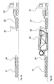
- Figs. 2a to 2d illustrate the main transport actions demonstrating logistic features of an advantageous embodiment of the invention.
- Fig. 2a illustrates two wheel sets according to the invention.
- the wheel sets comprise attachment precautions, which are described below.
- the wheel sets are basically modular trailers 21, 22.
- the trailers 21, 22 comprise means, e.g. hydraulic means (not shown) for lowering or raising the wheels.
- the trailer 21 comprises one attachment arrangement 24 and the trailer 22 comprises another attachment arrangement 25.
- the trailers 21, 22 and the nacelle 20 constitute a combined vehicle, which may be pulled by e.g. a truck 23 or other kinds of suitably powered vehicles.
- the illustrated vehicle is mounted with a sub-cover 28 adapted for protecting the sub-portion of the nacelle 20 against scratches etc. during transport.
- Fig. 2d illustrates the trailers 21, 22 that have now been unloaded, typically by lowering the trailers 21, 22, detaching the nacelle 20 and removing the trailers 21, 22 from the nacelle 20.
- trailers 21, 22 may be mutually coupled thereby forming one combined trailer, which may be transported by e.g. truck.
- fig. 2b illustrates a trailer made up by two trailers 21, 22 and a nacelle 20 in combination
- the trailer in fig. 2d basically illustrates a new trailer formed by the trailers 21, 22.
- the new trailer may now be formed by two relatively short trailers 21, 22. Therefore, the new trailer may typically form part of a vehicle, e.g. including truck, having a length of less than e.g. 18 meters. This means that the homebound (return) transportation of the trailers 21, 22 may be a simple operation, which may be performed without escort and requirements for numerous different transport applications, permissions etc. by the relevant authorities.
- the above-described preferred embodiment of the invention features an "onboard lift".
- the loading of the nacelle onto the trailers may be performed by means of a traditional external lift, although the preferred load/unload procedure is performed by means of lifting means integrated in the trailer or trailers.
- Fig. 3a illustrates some advantageous features of the above-described embodiment of the invention with respect to force distribution and orientation.
- the illustration illustrates the principle mechanical attachment of the rear part of the nacelle 20 to the trailer 22.
- the nacelle 20 comprises a rear attachment arrangement.
- the rear attachment comprises four attachment members 71, 72, of which only two are shown in a cross-section, one on each side of the rear part of the nacelle 20.
- the attachment members 71, 72 are fitted to or comprised in the main frame 10 of the nacelle 20.
- the attachment members facilitate mechanical four-point coupling of the main frame to the attachment arrangement 25 of the trailer 22, which creates absorption of moment both in the vertical and horizontal direction.
- the trailer 22 comprises an attachment arrangement 301 fitted with attachment fittings 302, 303 attachable to the aforementioned attachment means 71, 72.
- a hydraulic arrangement 304 forms part of the attachment arrangement.
- the hydraulic arrangement 304 is capable of evening out force exercised on the axles of the trailer 22.
- hydraulic arrangement 304 may advantageously be applied for absorbing moment variation by means of suitable measuring and control equipment not shown.
- suspension of the nacelle 20 by the above-described attachment arrangement may absorb high moment and be able to transfer force F to the axles of the trailer 22 in such a way that the resulting force F exercised on the axles is relatively uniform.
- the main frame 10 of the nacelle 20 should be dimensioned in such a way that it is able to absorb the moment transferred from the attachment arrangement, alone or in combination with other attachment arrangements, e.g. a front attachment arrangement.
- Fig. 3b illustrates some advantageous features of the above-described embodiment of the invention with respect to force distribution and orientation.
- the illustration illustrates the principle mechanical attachment of the front part of the nacelle 20 to the trailer 21.
- the main functionality of the illustrated suspension is the same as that of the above-described suspension, i.e. to even out force exercised on the axles of the trailer 21 as much as possible.
- the illustrated suspension is obtained by suspending the nacelle 20 to an attachment arrangement 24 on the trailer 21.
- the attachment arrangement 24 receives an attachment arrangement of the nacelle 20, here comprised by the hub 27 of the nacelle 20.
- the hub 27 must be able to absorb the induced moment in combination with the main frame of the nacelle 20.
- Fig. 4 basically illustrates the moment absorbed by suspension according to the invention. Again, the suspension should feature the ability to absorb a suitably high moment in order to even out force F exercised on the trailer axles.
- Figs. 5a, 6a and 7a illustrate the principles of different preferred suspension arrangements according to the different embodiments of the invention.
- Figs. 5b, 6b and 7b illustrate different applicable combinations of suspension arrangements according to the invention. Evidently, several other combinations may be applied within the scope of the invention than the three-point and four-point suspensions mentioned below.
- Fig. 5a illustrates the cross-section of discrete point suspension according to one embodiment of the invention.
- suspension is supplemented by further discrete point suspension in the plane.
- fig. 5a illustrates suspension of a nacelle part 52 to a trailer part 51.
- the illustrated suspension is established by suspension of discrete points 53, 54, 55 in one cross-section.
- the force F directed to the points 53, 54 is transferred by means of a moment absorbing arrangement, here comprised by a hydraulic cylinder 56.
- Fig. 5b illustrates four-point suspension of a nacelle as illustrated and explained in fig. 5a seen from above.
- four-point suspension refers to suspension in which a nacelle is basically attached to four areas when seen from above (i.e. not necessarily four points exclusively).
- the illustrated four-point suspension is basically capable of absorbing moment as illustrated in fig. 5a, i.e. a gravity force distribution arrangement. In addition, it is also capable of absorbing moment in the transverse direction, as illustrated in fig. 5b.
- Fig. 6a illustrates the cross-section of a rigid moment-absorbing arrangement 63.
- rigid suspension is established between a nacelle part 62 and a trailer part 61 by means of a rigid mechanical construction 63.
- 6b illustrates suspension of a nacelle as illustrated and explained in fig. 6a when seen from above, i.e. here by means of two rigid moment-absorbing arrangements 63 capable of absorbing suspension moment in both the vertical and horizontal direction.
- Fig. 7a illustrates a further embodiment of the invention, here more or less corresponding to the hub suspension illustrated in figs. 2a-d and figs. 3a-b.
- a nacelle part 72 is suspended to a trailer part 71.
- the trailer part 71 is mounted with a hub receiving arrangement 74, to which the hub 73 of a wind turbine nacelle 72 is attached e.g. by bolts in the points 75.
- the moment conversion arrangement facilitates distribution of force on the trailer axles in a more homogeneous manner.
- force exercised on the axles of a trailer in which the nacelle is suspended may be uniformly or at least relatively uniformly distributed on the axles of the trailer.
- Fig. 7b may also be referred to as three-point suspension (with respect to horizontal moment force).
- fig. 7 illustrates a "three-point" suspension, wherein a hub 73 comprises part of a front-moment absorbing arrangement and wherein two hydraulic cylinders 56 comprise part of a rear-moment absorbing arrangement.
Landscapes
- Engineering & Computer Science (AREA)
- Mechanical Engineering (AREA)
- Life Sciences & Earth Sciences (AREA)
- Sustainable Development (AREA)
- Sustainable Energy (AREA)
- Chemical & Material Sciences (AREA)
- Combustion & Propulsion (AREA)
- General Engineering & Computer Science (AREA)
- Health & Medical Sciences (AREA)
- Public Health (AREA)
- Transportation (AREA)
- Wind Motors (AREA)
- Body Structure For Vehicles (AREA)
- Vehicle Body Suspensions (AREA)
- Structures Of Non-Positive Displacement Pumps (AREA)
- Motor Power Transmission Devices (AREA)
- Packaging Of Machine Parts And Wound Products (AREA)
Claims (18)
- Fahrzeug, das wenigstens zwei Radsätze (21, 22) und wenigstens eine selbsttragende Windturbinengondel (20) umfasst, wobei, die Gondel (20) zwischen den wenigstens zwei Radsätzen (21, 22) so angeordnet ist, dass sie zwischen den wenigstens zwei Radsätzen (21, 22) hängt.
- Fahrzeug gemäß Anspruch 1, wobei wenigstens einer der Radsätze (21, 22) einen Trailer (21, 22) bildet.
- Fahrzeug gemäß Anspruch 1 oder 2, wobei wenigstens einer der Radsätze (21, 22) eine Höhenverstellungseinrichtung umfasst.
- Fahrzeug gemäß einem der Ansprüche 1-3, wobei die Höhenverstellungseinrichtung in die Radsätze (21, 22) integriert ist.
- Fahrzeug gemäß einem der Ansprüche 1-4, wobei das Fahrzeug ein momentabsorbierendes Befestigungsmittel (21, 25) umfasst.
- Fahrzeug gemäß einem der Ansprüche 1-5, wobei das momentabsorbierende Befestigungsmittel (24, 25) ein variables momentabsorbierendes Befestigungsmittel (24, 25) umfasst.
- Fahrzeug gemäß einem der Anspüche 1-6, wobei das momentabsorbierende Befestigungsmittel (24, 25) die Nabe (27) der Gondel (20) umfasst.
- Fahrzeug gemäß einem der Ansprüche 1-7, wobei eine untere Abdeckung (28) zum Schutz des unteren Bereichs der Gondel (20) ausgebildet ist.
- Verwendung wenigstens eines Fahrzeugs gemäß Ansprüchen 1 bis 8 zum Transport wenigstens einer Gondel (20).
- Gondel (20), die ein lösbares Befestigungsmittel (71, 72, 27) aufweist, wobei das Befestigungsmittel (71, 72, 27) zur Aufhängung der Gondel (20) zwischen wenigstens zwei Radsätzen (21, 22) als vollständig oder teilweise selbsttragende Aufhängung ausgebildet ist, wobei die Gondel (20) selbsttragend zwischen dem Befestigungsmittel (71, 72, 27) ist.
- Gondel (20) gemäß Anspruch 10, wobei das Befestigungsmittel (71, 72, 27) wenigstens zwei Befestigungsanordnungen umfasst.
- Gondel (20) gemäß den Ansprüchen 10 oder 11, wobei das Befestigungsmittel (71, 72, 27) wenigstens eine vordere Befestigungsanordnung und wenigstens eine hintere Befestigungsanordnung umfasst.
- Gondel (20) gemäß einem der Ansprüche 10 bis 12, wobei die vordere Befestigung wenigstens einen Teil der Nabe (27) umfasst.
- Gondel (20) gemäß einem der Ansprüche 10 bis 13, wobei eine untere Abdeckung (28) zum Schutz des unteren Bereichs der Gondel (20) ausgebildet ist.
- Verfahren zum Transport wenigstens einer Windturbinengondel (20), die mit wenigstens zwei Radsätzen (21, 22) versehen ist, und zur Aufhängung der Windturbinengondel (20) zwischen den Radsätzen (21, 22), so dass sie zwischen den Radsätzen (21, 22) hängt.
- Verfahren zum Transport wenigstens einer Windturbinengondel (20) gemäß Anspruch 15, wobei wenigstens zwei Radsätze (21, 22) lösbare Befestigungsmittel (24, 25) aufweisen, und wenigstens eines der lösbaren Befestigungsmittel mit einer Hubeinrichtung anhebbar ist, und die Windturbinengondel (20) an den wenigstens zwei Radsätzen (21, 22) mittels der lösbaren Befestigungsmittel befestigt ist, und die Gondel (20) mit wenigstens einer der Befestigungsanordnungen angehoben wird.
- Verfahren zum Transport von wenigstens einer Windturbinengondel (20) gemäß Anspruch 15 und 16, wobei die Gondel (20) eine Gondel gemäß einem der Ansprüche 10 bis 14 ist.
- Verfahren zum Laden wenigstens einer Windturbinengondel (20) auf eine Fahrzeug-Anordnung mit wenigstens zwei Radsätzen (21, 22), wobei das Verfahren die Schritte umfasst,
Verbinden der wenigstens einen Windturbinengondel (20) mit den wenigstens zwei Radsätzen (21, 22),
Anheben der wenigstens einen Windturbinengondel (20) durch eine in die Radsätze (21, 22) integrierte Höhenverstellungseinrichtung und
Aufhängen der wenigstens einen Windturbinengondel (20) zwischen den wenigstens zwei Radsätzen (21, 22).
Priority Applications (2)
| Application Number | Priority Date | Filing Date | Title |
|---|---|---|---|
| EP03704340.3A EP1476658B2 (de) | 2002-02-19 | 2003-02-19 | Verfahren zum transport einer windturbinengondel und verwendung hiervon |
| DE60301950.1T DE60301950T3 (de) | 2002-02-19 | 2003-02-19 | Verfahren zum transport einer windturbinengondel und verwendung hiervon |
Applications Claiming Priority (4)
| Application Number | Priority Date | Filing Date | Title |
|---|---|---|---|
| EP02075658 | 2002-02-19 | ||
| EP02075658A EP1336755A1 (de) | 2002-02-19 | 2002-02-19 | Verfahren zum Transport von einer Maschinengondel einer Windturbine |
| EP03704340.3A EP1476658B2 (de) | 2002-02-19 | 2003-02-19 | Verfahren zum transport einer windturbinengondel und verwendung hiervon |
| PCT/DK2003/000109 WO2003071130A1 (en) | 2002-02-19 | 2003-02-19 | Method of transportation of a wind turbine nacelle and use thereof |
Publications (3)
| Publication Number | Publication Date |
|---|---|
| EP1476658A1 EP1476658A1 (de) | 2004-11-17 |
| EP1476658B1 true EP1476658B1 (de) | 2005-10-19 |
| EP1476658B2 EP1476658B2 (de) | 2016-06-01 |
Family
ID=27619172
Family Applications (2)
| Application Number | Title | Priority Date | Filing Date |
|---|---|---|---|
| EP02075658A Withdrawn EP1336755A1 (de) | 2002-02-19 | 2002-02-19 | Verfahren zum Transport von einer Maschinengondel einer Windturbine |
| EP03704340.3A Expired - Lifetime EP1476658B2 (de) | 2002-02-19 | 2003-02-19 | Verfahren zum transport einer windturbinengondel und verwendung hiervon |
Family Applications Before (1)
| Application Number | Title | Priority Date | Filing Date |
|---|---|---|---|
| EP02075658A Withdrawn EP1336755A1 (de) | 2002-02-19 | 2002-02-19 | Verfahren zum Transport von einer Maschinengondel einer Windturbine |
Country Status (11)
| Country | Link |
|---|---|
| US (1) | US7793964B2 (de) |
| EP (2) | EP1336755A1 (de) |
| JP (1) | JP4441268B2 (de) |
| CN (1) | CN1636112B (de) |
| AT (1) | ATE307288T1 (de) |
| AU (1) | AU2003206685B2 (de) |
| CA (1) | CA2476751C (de) |
| DE (1) | DE60301950T3 (de) |
| DK (1) | DK1476658T4 (de) |
| ES (1) | ES2253658T5 (de) |
| WO (1) | WO2003071130A1 (de) |
Cited By (1)
| Publication number | Priority date | Publication date | Assignee | Title |
|---|---|---|---|---|
| WO2010142304A1 (de) * | 2009-06-08 | 2010-12-16 | Powerwind Gmbh | Windenergieanlage und gondel dafür |
Families Citing this family (33)
| Publication number | Priority date | Publication date | Assignee | Title |
|---|---|---|---|---|
| DE60319152T2 (de) * | 2003-03-21 | 2009-03-19 | Vestas Wind Systems A/S | Verfahren zum bewegen der rotationsmittel einer windturbine während des transports oder stillstandes, gondel, hilfsvorrichtung und deren verwendung |
| ATE415311T1 (de) | 2003-05-15 | 2008-12-15 | Vestas Wind Sys As | Transportsystem für ein windturbinenbauteil und verfahren zum transport eines windturbinenbauteils |
| US7210882B2 (en) * | 2003-07-03 | 2007-05-01 | Vestas-American Wind Technology | System and process for transporting wind turbines |
| US20070177954A1 (en) * | 2006-01-31 | 2007-08-02 | General Electric Company | Method and apparatus for containing and/or transporting rotor blades |
| US7704024B2 (en) * | 2006-01-31 | 2010-04-27 | General Electric Company | Methods and systems for transporting wind turbine components |
| CN101479471B (zh) * | 2006-06-29 | 2013-03-20 | 维斯塔斯风力系统有限公司 | 用于风轮机机舱的处理系统、用于垂直移置风轮机机舱的方法及风轮机机舱 |
| US20080187424A1 (en) * | 2007-02-06 | 2008-08-07 | Garcia Alberto M | Transport For A Wind Tower And Methods Thereof |
| US20090206604A1 (en) * | 2008-02-15 | 2009-08-20 | Karl-Heinz Meiners | Method of transporting bulky equipment of a wind power plant, preassembled equipment |
| CN102123886B (zh) * | 2008-08-18 | 2014-03-19 | 西门子公司 | 用于将风力涡轮机元件固定到车辆的固定系统和方法 |
| US20100054907A1 (en) * | 2008-09-03 | 2010-03-04 | Puls Ingo | Universal vehicle |
| CN101434325B (zh) * | 2008-12-19 | 2011-08-24 | 严强 | 一种垂直轴风力发电机的运输方法 |
| WO2010102635A2 (en) * | 2009-03-13 | 2010-09-16 | Vestas Wind Systems A/S | Wind turbine nacelle |
| US8096739B1 (en) | 2009-04-08 | 2012-01-17 | Bnsf Railway Company | Method and apparatus for transporting wind turbine blades |
| WO2011051272A2 (en) * | 2009-10-27 | 2011-05-05 | Vestas Wind Systems A/S | A wind turbine |
| DK2327655T3 (da) * | 2009-11-30 | 2012-09-24 | Siemens Ag | Indretning til transport af vindmøllekomponenter |
| ES2396670T3 (es) * | 2010-01-18 | 2013-02-25 | Siemens Aktiengesellschaft | Disposición y método de transporte para segmento de torre de turbina eólica |
| DK2395240T3 (en) * | 2010-06-11 | 2015-11-16 | Siemens Ag | Windkraftanlagen Nacelle, transport to a wind turbines nacelle and method for transporting a wind turbines nacelle |
| US9434291B2 (en) * | 2010-10-15 | 2016-09-06 | Bnsf Railway Company | Method and apparatus for transporting wind turbine blades |
| US20120090501A1 (en) * | 2010-10-15 | 2012-04-19 | Kelly Thomas P | System and apparatus for multi-modal transportation |
| US9709038B2 (en) * | 2010-12-15 | 2017-07-18 | Vestas Wind Systems A/S | Tool and a method for moving a wind turbine drivetrain component |
| US20120201636A1 (en) * | 2011-02-07 | 2012-08-09 | Vestas Wind Systems A/S | Transportation device for a wind turbine component and method of using same |
| US8528735B2 (en) * | 2011-03-30 | 2013-09-10 | General Electric Company | Transport frame for nacelle/rotor hub unit of a wind turbine, method of transporting and mounting a nacelle/rotor hub unit |
| DK177465B1 (en) | 2012-03-09 | 2013-06-24 | Envision Energy Denmark Aps | Nacelle stand and a method for assembling and testing a nacelle for a wind turbine |
| US9833803B2 (en) * | 2014-05-15 | 2017-12-05 | David Hart | Apparatus and method for sanitizing |
| EP3088731B1 (de) * | 2015-04-30 | 2019-11-06 | Siemens Gamesa Renewable Energy A/S | Transportsystem zum transportieren eines generators einer windturbine und verfahren zum transportieren des generators |
| WO2021094570A1 (en) | 2019-11-15 | 2021-05-20 | Jupiter Bach A/S | Nacelle for a wind turbine |
| DK201970699A1 (en) | 2019-11-15 | 2021-07-15 | Jupiter Bach As | Utilization of a composite nacelle cover as the load-carrying Structure for main machinery components. |
| WO2021094569A1 (en) | 2019-11-15 | 2021-05-20 | Jupiter Bach A/S | Nacelle cover for a wind turbine |
| EP4045797B1 (de) | 2019-11-15 | 2024-07-10 | Jupiter Bach A/S | Gondel für eine windturbine |
| US12228106B2 (en) | 2019-12-30 | 2025-02-18 | Vestas Wind Systems A/S | Transport frame for a nacelle of a wind turbine and associated methods |
| DK3882459T3 (da) * | 2020-03-17 | 2023-07-03 | Siemens Gamesa Renewable Energy As | Fremgangsmåde og system til transport af en komponent til en vindmølle |
| CN112696323A (zh) * | 2020-12-30 | 2021-04-23 | 三一重能股份有限公司 | 轮毂运载组件及轮毂运载系统 |
| US12196175B2 (en) * | 2021-06-02 | 2025-01-14 | Mammoet Usa South, Inc. | Lift system and method for wind turbine monopiles and other structures |
Family Cites Families (45)
| Publication number | Priority date | Publication date | Assignee | Title |
|---|---|---|---|---|
| US1996695A (en) | 1933-05-09 | 1935-04-02 | Jr William J Bigley | Transportation method and means |
| DE872432C (de) † | 1943-02-03 | 1953-04-02 | Suedwerke Motoren Und Kraftwag | Fahrzeug zur Befoerderung schwerer Lasten auf Strassen und im Gelaende |
| DE872453C (de) * | 1943-06-22 | 1953-04-02 | Bosch Gmbh Robert | Bremszylinder, insbesondere fuer Druckmittel-Kraftfahrzeugbremsen |
| US2936910A (en) * | 1956-10-03 | 1960-05-17 | Delta Tank Mfg Co Inc | Portable storage plant |
| DE1136902B (de) | 1960-07-04 | 1962-09-20 | Rathgeber Ag Waggonfab Jos | Fahrwerk zum Transport von Rolltreppen |
| US3193301A (en) * | 1961-05-26 | 1965-07-06 | Elmer H Talbert | Universal transporters |
| US3392857A (en) * | 1963-07-25 | 1968-07-16 | Fruehauf Corp | Separable wheeled units for vehiclizing containers |
| US3243193A (en) * | 1964-07-02 | 1966-03-29 | Gichner Mobile Systems Inc | Hydraulically operated demountable running gear |
| US3315974A (en) * | 1965-11-26 | 1967-04-25 | Craig Systems Corp | Portable dolly with articulated adjustable truss |
| US3420541A (en) * | 1966-09-26 | 1969-01-07 | Ass Elect Ind | Transporters |
| US3438652A (en) * | 1967-01-25 | 1969-04-15 | Don L Hoffacker | Snobble trailer |
| US3520430A (en) * | 1968-12-05 | 1970-07-14 | Glenn G Dunbar | Loading and hauling apparatus |
| DE1904938B1 (de) * | 1969-02-01 | 1970-10-22 | Fries Gmbh Heinrich De | Transportvorrichtung fuer Grossbehaelter |
| US3626867A (en) * | 1969-08-22 | 1971-12-14 | Gen Am Transport | Railway tank car and external support ring therefor |
| DE2116842A1 (de) * | 1970-04-08 | 1971-10-21 | J Tranchero | Fahrbarer, zum Aufbau auf Kraftfahrzeuge bestimmter Kran mit drei hydraulisch gesteuerten Hebestufen |
| US3929241A (en) * | 1971-08-21 | 1975-12-30 | Zachry Co H B | Transport rig |
| US3795336A (en) * | 1971-10-07 | 1974-03-05 | Reliance Trailer Mfg Inc | Apparatus for transporting building modules |
| US3834111A (en) * | 1971-10-07 | 1974-09-10 | Reliance Trailer Mfg Inc | Method for transporting building modules |
| US3801132A (en) * | 1972-08-29 | 1974-04-02 | J A Jones Constr Co | Extendible boom and mast trailer |
| DE7401022U (de) | 1974-01-12 | 1974-04-25 | De Fries H Gmbh | Vorrichtung zur Verwandlung von Ladegut in eine Lasteinheit |
| US4199298A (en) * | 1977-12-05 | 1980-04-22 | Tbw Industries, Inc. | Trailer for skid mounted tanks |
| AU4030078A (en) | 1978-08-08 | 1980-09-04 | Hargreaves T R | Container towing device |
| US4231709A (en) * | 1978-12-15 | 1980-11-04 | Craig Systems Corporation | Demountable transporter for containers |
| US4237384A (en) * | 1979-06-27 | 1980-12-02 | Kennon Woodrow A | Wind turbine means |
| US4260141A (en) * | 1979-07-16 | 1981-04-07 | Pennsylvania Engineering Corporation | Centerplate wear liners |
| US4452555A (en) * | 1981-09-18 | 1984-06-05 | The Union Corporation | Attachment apparatus |
| NL8201283A (nl) * | 1982-03-26 | 1983-10-17 | Fdo Techn Adviseurs | Deelbare gondel voor een windmolen. |
| US4570959A (en) | 1984-09-13 | 1986-02-18 | The United States Of America As Represented By The Secretary Of The Army | Dolly unit |
| US4792700A (en) * | 1987-04-14 | 1988-12-20 | Ammons Joe L | Wind driven electrical generating system |
| US4729570A (en) * | 1987-05-07 | 1988-03-08 | B & K Leasing Corporation | Fiberglass transport trailer |
| DE4310171A1 (de) | 1993-03-29 | 1994-10-06 | Kamag Transporttech Gmbh | Hubfahrzeug zum Umschlag von Lasten über Paletten |
| DK9500262U4 (da) † | 1995-07-07 | 1996-10-07 | Bonus Energy As | Bundramme til vindmøllehus samt vindmølle omfattende samme |
| US5779255A (en) * | 1996-05-29 | 1998-07-14 | Garcia, Jr.; Daniel C. | Vessel transport carrier and method for transporting such vessel |
| JP2000006849A (ja) | 1998-06-19 | 2000-01-11 | Munemoto Onishi | 車両用床裏カバー |
| EP1003182A1 (de) * | 1998-11-20 | 2000-05-24 | ABB Trasformatori S.p.A. | Transformator, insbesondere für fahrbare und nicht-ortsfeste Unterstationen für die Übertragung und Verteilung von elektrischer Energie auf Hoch-, Mittel- und-Niederspannung |
| DE19916453A1 (de) † | 1999-04-12 | 2000-10-19 | Flender A F & Co | Windkraftanlage |
| JP3853109B2 (ja) | 1999-07-06 | 2006-12-06 | 本田技研工業株式会社 | アンダーカバー |
| DK173530B2 (da) † | 1999-11-17 | 2005-07-18 | Siemens Wind Power As | Fremgangsmåde til montering af hovedkomponenter i kabine på vindmölle og en sådan kabine til vindmölle |
| JP2001233252A (ja) | 2000-02-24 | 2001-08-28 | Fuji Heavy Ind Ltd | アンダーカバー |
| NZ523576A (en) | 2000-07-10 | 2006-08-31 | Aloys Wobben | Device for handling unit loads |
| DE10063136B4 (de) | 2000-07-10 | 2007-03-08 | Wobben, Aloys, Dipl.-Ing. | Vorrichtung zum Handhaben von Stückgütern |
| JP3809855B2 (ja) * | 2000-08-17 | 2006-08-16 | 日本通運株式会社 | 搬送用車両 |
| DE60319152T2 (de) * | 2003-03-21 | 2009-03-19 | Vestas Wind Systems A/S | Verfahren zum bewegen der rotationsmittel einer windturbine während des transports oder stillstandes, gondel, hilfsvorrichtung und deren verwendung |
| ATE415311T1 (de) * | 2003-05-15 | 2008-12-15 | Vestas Wind Sys As | Transportsystem für ein windturbinenbauteil und verfahren zum transport eines windturbinenbauteils |
| DK177128B1 (da) * | 2003-07-10 | 2011-12-19 | Lm Glasfiber As | Transport og opbevaring af forkrumme vindmøllevinger |
-
2002
- 2002-02-19 EP EP02075658A patent/EP1336755A1/de not_active Withdrawn
-
2003
- 2003-02-19 AU AU2003206685A patent/AU2003206685B2/en not_active Expired
- 2003-02-19 CN CN038041944A patent/CN1636112B/zh not_active Expired - Lifetime
- 2003-02-19 AT AT03704340T patent/ATE307288T1/de not_active IP Right Cessation
- 2003-02-19 EP EP03704340.3A patent/EP1476658B2/de not_active Expired - Lifetime
- 2003-02-19 DE DE60301950.1T patent/DE60301950T3/de not_active Expired - Lifetime
- 2003-02-19 DK DK03704340.3T patent/DK1476658T4/en active
- 2003-02-19 JP JP2003570004A patent/JP4441268B2/ja not_active Expired - Fee Related
- 2003-02-19 CA CA2476751A patent/CA2476751C/en not_active Expired - Lifetime
- 2003-02-19 US US10/504,949 patent/US7793964B2/en not_active Expired - Lifetime
- 2003-02-19 ES ES03704340.3T patent/ES2253658T5/es not_active Expired - Lifetime
- 2003-02-19 WO PCT/DK2003/000109 patent/WO2003071130A1/en not_active Ceased
Cited By (1)
| Publication number | Priority date | Publication date | Assignee | Title |
|---|---|---|---|---|
| WO2010142304A1 (de) * | 2009-06-08 | 2010-12-16 | Powerwind Gmbh | Windenergieanlage und gondel dafür |
Also Published As
| Publication number | Publication date |
|---|---|
| CA2476751A1 (en) | 2003-08-28 |
| WO2003071130A1 (en) | 2003-08-28 |
| EP1476658A1 (de) | 2004-11-17 |
| US20050123382A1 (en) | 2005-06-09 |
| AU2003206685B2 (en) | 2006-07-20 |
| EP1336755A1 (de) | 2003-08-20 |
| US7793964B2 (en) | 2010-09-14 |
| ES2253658T3 (es) | 2006-06-01 |
| DK1476658T4 (en) | 2016-09-05 |
| JP2005517591A (ja) | 2005-06-16 |
| EP1476658B2 (de) | 2016-06-01 |
| AU2003206685A1 (en) | 2003-09-09 |
| DE60301950T3 (de) | 2016-09-15 |
| ATE307288T1 (de) | 2005-11-15 |
| ES2253658T5 (es) | 2016-10-28 |
| DK1476658T3 (da) | 2006-02-27 |
| CN1636112B (zh) | 2010-07-14 |
| JP4441268B2 (ja) | 2010-03-31 |
| CN1636112A (zh) | 2005-07-06 |
| DE60301950D1 (de) | 2006-03-02 |
| CA2476751C (en) | 2012-01-10 |
| DE60301950T2 (de) | 2006-07-27 |
Similar Documents
| Publication | Publication Date | Title |
|---|---|---|
| EP1476658B1 (de) | Verfahren zum transport einer windturbinengondel und verwendung hiervon | |
| AU2007264212B2 (en) | A handling system for a wind turbine nacelle, methods for transport and vertical displacement of a wind turbine nacelle and a use of a handling system | |
| JP4358751B2 (ja) | 風力タービン部品用の搬送システム、搬送システム用車両、変位システム、搬送又は変位システムを確立する方法及びその使用 | |
| US9194375B2 (en) | Method for installing a wind turbine, a nacelle for a wind turbine, and method for transporting elements of a wind turbine | |
| US9403559B1 (en) | Helicopter transport apparatus | |
| US10023252B1 (en) | Intermodal container with chassis | |
| CN104121144A (zh) | 风力发电设备的组装方法 | |
| CN103832508A (zh) | 具有起降、保障功能的直升机拖车 | |
| CN107839896B (zh) | 一种机场物资装卸平台底盘 | |
| CN208978743U (zh) | 集装箱运输车辆用半挂车 | |
| CN101353062B (zh) | 骨架车 | |
| CN105620564B (zh) | 一种随变的模块离合式半挂车 | |
| CN203681702U (zh) | 具有起降、保障功能的直升机拖车 | |
| RU2347711C2 (ru) | СПОСОБ ТРАНСПОРТИРОВКИ ВЕРТОЛЕТА ТИПА Ми-8 ТРЕЙЛЕРОМ И ОСНАСТКА ДЛЯ РАЗМЕЩЕНИЯ И ШВАРТОВКИ ВЕРТОЛЕТА ТИПА Ми-8 ПРИ ТРАНСПОРТИРОВКЕ ЕГО ТРЕЙЛЕРОМ | |
| CN102485572A (zh) | 商用车运输半挂车 | |
| DE202010017618U1 (de) | Transportsystem zum Transportieren schwerer Lasten | |
| BR102012021825A2 (pt) | Reboque para coleta de resíduos eletroeletrônicos | |
| CN110065648A (zh) | 一种用于大型系留气球系留和转场运输的锚泊半挂底盘 | |
| KR20150049051A (ko) | 중부하 운송수단용 회전반경 축소장치 |
Legal Events
| Date | Code | Title | Description |
|---|---|---|---|
| PUAI | Public reference made under article 153(3) epc to a published international application that has entered the european phase |
Free format text: ORIGINAL CODE: 0009012 |
|
| AK | Designated contracting states |
Kind code of ref document: A1 Designated state(s): AT BE BG CH CY CZ DE DK EE ES FI FR GB GR HU IE IT LI LU MC NL PT SE SI SK TR |
|
| AX | Request for extension of the european patent |
Extension state: AL LT LV MK RO |
|
| 17P | Request for examination filed |
Effective date: 20040803 |
|
| 17Q | First examination report despatched |
Effective date: 20050125 |
|
| GRAP | Despatch of communication of intention to grant a patent |
Free format text: ORIGINAL CODE: EPIDOSNIGR1 |
|
| GRAS | Grant fee paid |
Free format text: ORIGINAL CODE: EPIDOSNIGR3 |
|
| GRAA | (expected) grant |
Free format text: ORIGINAL CODE: 0009210 |
|
| AK | Designated contracting states |
Kind code of ref document: B1 Designated state(s): AT BE BG CH CY CZ DE DK EE ES FI FR GB GR HU IE IT LI LU MC NL PT SE SI SK TR |
|
| PG25 | Lapsed in a contracting state [announced via postgrant information from national office to epo] |
Ref country code: CZ Free format text: LAPSE BECAUSE OF FAILURE TO SUBMIT A TRANSLATION OF THE DESCRIPTION OR TO PAY THE FEE WITHIN THE PRESCRIBED TIME-LIMIT Effective date: 20051019 Ref country code: BE Free format text: LAPSE BECAUSE OF FAILURE TO SUBMIT A TRANSLATION OF THE DESCRIPTION OR TO PAY THE FEE WITHIN THE PRESCRIBED TIME-LIMIT Effective date: 20051019 Ref country code: SK Free format text: LAPSE BECAUSE OF FAILURE TO SUBMIT A TRANSLATION OF THE DESCRIPTION OR TO PAY THE FEE WITHIN THE PRESCRIBED TIME-LIMIT Effective date: 20051019 Ref country code: AT Free format text: LAPSE BECAUSE OF FAILURE TO SUBMIT A TRANSLATION OF THE DESCRIPTION OR TO PAY THE FEE WITHIN THE PRESCRIBED TIME-LIMIT Effective date: 20051019 Ref country code: LI Free format text: LAPSE BECAUSE OF FAILURE TO SUBMIT A TRANSLATION OF THE DESCRIPTION OR TO PAY THE FEE WITHIN THE PRESCRIBED TIME-LIMIT Effective date: 20051019 Ref country code: SI Free format text: LAPSE BECAUSE OF FAILURE TO SUBMIT A TRANSLATION OF THE DESCRIPTION OR TO PAY THE FEE WITHIN THE PRESCRIBED TIME-LIMIT Effective date: 20051019 Ref country code: FI Free format text: LAPSE BECAUSE OF FAILURE TO SUBMIT A TRANSLATION OF THE DESCRIPTION OR TO PAY THE FEE WITHIN THE PRESCRIBED TIME-LIMIT Effective date: 20051019 Ref country code: CH Free format text: LAPSE BECAUSE OF FAILURE TO SUBMIT A TRANSLATION OF THE DESCRIPTION OR TO PAY THE FEE WITHIN THE PRESCRIBED TIME-LIMIT Effective date: 20051019 |
|
| REG | Reference to a national code |
Ref country code: GB Ref legal event code: FG4D |
|
| REG | Reference to a national code |
Ref country code: CH Ref legal event code: EP |
|
| REG | Reference to a national code |
Ref country code: IE Ref legal event code: FG4D |
|
| PG25 | Lapsed in a contracting state [announced via postgrant information from national office to epo] |
Ref country code: BG Free format text: LAPSE BECAUSE OF FAILURE TO SUBMIT A TRANSLATION OF THE DESCRIPTION OR TO PAY THE FEE WITHIN THE PRESCRIBED TIME-LIMIT Effective date: 20060119 Ref country code: SE Free format text: LAPSE BECAUSE OF FAILURE TO SUBMIT A TRANSLATION OF THE DESCRIPTION OR TO PAY THE FEE WITHIN THE PRESCRIBED TIME-LIMIT Effective date: 20060119 Ref country code: GR Free format text: LAPSE BECAUSE OF FAILURE TO SUBMIT A TRANSLATION OF THE DESCRIPTION OR TO PAY THE FEE WITHIN THE PRESCRIBED TIME-LIMIT Effective date: 20060119 |
|
| REG | Reference to a national code |
Ref country code: DK Ref legal event code: T3 |
|
| PG25 | Lapsed in a contracting state [announced via postgrant information from national office to epo] |
Ref country code: MC Free format text: LAPSE BECAUSE OF NON-PAYMENT OF DUE FEES Effective date: 20060228 Ref country code: LU Free format text: LAPSE BECAUSE OF NON-PAYMENT OF DUE FEES Effective date: 20060228 |
|
| REF | Corresponds to: |
Ref document number: 60301950 Country of ref document: DE Date of ref document: 20060302 Kind code of ref document: P |
|
| PG25 | Lapsed in a contracting state [announced via postgrant information from national office to epo] |
Ref country code: PT Free format text: LAPSE BECAUSE OF FAILURE TO SUBMIT A TRANSLATION OF THE DESCRIPTION OR TO PAY THE FEE WITHIN THE PRESCRIBED TIME-LIMIT Effective date: 20060320 |
|
| PG25 | Lapsed in a contracting state [announced via postgrant information from national office to epo] |
Ref country code: HU Free format text: LAPSE BECAUSE OF FAILURE TO SUBMIT A TRANSLATION OF THE DESCRIPTION OR TO PAY THE FEE WITHIN THE PRESCRIBED TIME-LIMIT Effective date: 20060420 |
|
| REG | Reference to a national code |
Ref country code: CH Ref legal event code: PL |
|
| REG | Reference to a national code |
Ref country code: ES Ref legal event code: FG2A Ref document number: 2253658 Country of ref document: ES Kind code of ref document: T3 |
|
| PLBI | Opposition filed |
Free format text: ORIGINAL CODE: 0009260 |
|
| PLAZ | Examination of admissibility of opposition: despatch of communication + time limit |
Free format text: ORIGINAL CODE: EPIDOSNOPE2 |
|
| PLBI | Opposition filed |
Free format text: ORIGINAL CODE: 0009260 |
|
| 26 | Opposition filed |
Opponent name: ENERCON GMBH Effective date: 20060715 |
|
| 26 | Opposition filed |
Opponent name: ENERCON GMBH Effective date: 20060715 Opponent name: GAMESA EOLICA, S.A. (SOCIEDAD UNIPERSONAL) Effective date: 20060719 |
|
| PLAX | Notice of opposition and request to file observation + time limit sent |
Free format text: ORIGINAL CODE: EPIDOSNOBS2 |
|
| PLBA | Examination of admissibility of opposition: reply received |
Free format text: ORIGINAL CODE: EPIDOSNOPE4 |
|
| NLR1 | Nl: opposition has been filed with the epo |
Opponent name: GAMESA EOLICA, S.A. (SOCIEDAD UNIPERSONAL) Opponent name: ENERCON GMBH |
|
| EN | Fr: translation not filed | ||
| PG25 | Lapsed in a contracting state [announced via postgrant information from national office to epo] |
Ref country code: FR Free format text: LAPSE BECAUSE OF FAILURE TO SUBMIT A TRANSLATION OF THE DESCRIPTION OR TO PAY THE FEE WITHIN THE PRESCRIBED TIME-LIMIT Effective date: 20061208 |
|
| PLAF | Information modified related to communication of a notice of opposition and request to file observations + time limit |
Free format text: ORIGINAL CODE: EPIDOSCOBS2 |
|
| PLAF | Information modified related to communication of a notice of opposition and request to file observations + time limit |
Free format text: ORIGINAL CODE: EPIDOSCOBS2 |
|
| PLBB | Reply of patent proprietor to notice(s) of opposition received |
Free format text: ORIGINAL CODE: EPIDOSNOBS3 |
|
| PLAB | Opposition data, opponent's data or that of the opponent's representative modified |
Free format text: ORIGINAL CODE: 0009299OPPO |
|
| R26 | Opposition filed (corrected) |
Opponent name: GAMESA EOLICA, S.A. (SOCIEDAD UNIPERSONAL) Effective date: 20060719 Opponent name: ENERCON GMBH Effective date: 20060715 |
|
| NLR1 | Nl: opposition has been filed with the epo |
Opponent name: GAMESA EOLICA, S.A. (SOCIEDAD UNIPERSONAL) Opponent name: ENERCON GMBH |
|
| PLAB | Opposition data, opponent's data or that of the opponent's representative modified |
Free format text: ORIGINAL CODE: 0009299OPPO |
|
| R26 | Opposition filed (corrected) |
Opponent name: ENERCON GMBH Effective date: 20060715 Opponent name: GAMESA EOLICA S.L. Effective date: 20060719 |
|
| NLR1 | Nl: opposition has been filed with the epo |
Opponent name: GAMESA EOELICA S.L. Opponent name: ENERCON GMBH |
|
| PG25 | Lapsed in a contracting state [announced via postgrant information from national office to epo] |
Ref country code: EE Free format text: LAPSE BECAUSE OF FAILURE TO SUBMIT A TRANSLATION OF THE DESCRIPTION OR TO PAY THE FEE WITHIN THE PRESCRIBED TIME-LIMIT Effective date: 20051019 |
|
| PG25 | Lapsed in a contracting state [announced via postgrant information from national office to epo] |
Ref country code: TR Free format text: LAPSE BECAUSE OF FAILURE TO SUBMIT A TRANSLATION OF THE DESCRIPTION OR TO PAY THE FEE WITHIN THE PRESCRIBED TIME-LIMIT Effective date: 20051019 |
|
| PG25 | Lapsed in a contracting state [announced via postgrant information from national office to epo] |
Ref country code: FR Free format text: LAPSE BECAUSE OF FAILURE TO SUBMIT A TRANSLATION OF THE DESCRIPTION OR TO PAY THE FEE WITHIN THE PRESCRIBED TIME-LIMIT Effective date: 20060228 |
|
| PLAB | Opposition data, opponent's data or that of the opponent's representative modified |
Free format text: ORIGINAL CODE: 0009299OPPO |
|
| PG25 | Lapsed in a contracting state [announced via postgrant information from national office to epo] |
Ref country code: FR Free format text: LAPSE BECAUSE OF FAILURE TO SUBMIT A TRANSLATION OF THE DESCRIPTION OR TO PAY THE FEE WITHIN THE PRESCRIBED TIME-LIMIT Effective date: 20051019 Ref country code: CY Free format text: LAPSE BECAUSE OF FAILURE TO SUBMIT A TRANSLATION OF THE DESCRIPTION OR TO PAY THE FEE WITHIN THE PRESCRIBED TIME-LIMIT Effective date: 20051019 |
|
| PLBP | Opposition withdrawn |
Free format text: ORIGINAL CODE: 0009264 |
|
| REG | Reference to a national code |
Ref country code: DE Ref legal event code: R082 Ref document number: 60301950 Country of ref document: DE Representative=s name: SAMSON & PARTNER, PATENTANWAELTE, DE Effective date: 20120202 Ref country code: DE Ref legal event code: R081 Ref document number: 60301950 Country of ref document: DE Owner name: VESTAS WIND SYSTEMS A/S, DK Free format text: FORMER OWNER: VESTAS WIND SYSTEMS A/S, RINGKOBING, FI Effective date: 20120202 Ref country code: DE Ref legal event code: R082 Ref document number: 60301950 Country of ref document: DE Representative=s name: SAMSON & PARTNER PATENTANWAELTE MBB, DE Effective date: 20120202 |
|
| RTI2 | Title (correction) |
Free format text: NACELLE AND METHOD OF LOADING A WIND TURBINE NACELLE COMPRISING ONE HUB ONTO A VEHICLE ARRANGEMENT |
|
| APAH | Appeal reference modified |
Free format text: ORIGINAL CODE: EPIDOSCREFNO |
|
| APBM | Appeal reference recorded |
Free format text: ORIGINAL CODE: EPIDOSNREFNO |
|
| APBP | Date of receipt of notice of appeal recorded |
Free format text: ORIGINAL CODE: EPIDOSNNOA2O |
|
| APBM | Appeal reference recorded |
Free format text: ORIGINAL CODE: EPIDOSNREFNO |
|
| APBP | Date of receipt of notice of appeal recorded |
Free format text: ORIGINAL CODE: EPIDOSNNOA2O |
|
| APBQ | Date of receipt of statement of grounds of appeal recorded |
Free format text: ORIGINAL CODE: EPIDOSNNOA3O |
|
| PLAB | Opposition data, opponent's data or that of the opponent's representative modified |
Free format text: ORIGINAL CODE: 0009299OPPO |
|
| R26 | Opposition filed (corrected) |
Opponent name: GAMESA EOLICA S.L. Effective date: 20060719 |
|
| RAP2 | Party data changed (patent owner data changed or rights of a patent transferred) |
Owner name: VESTAS WIND SYSTEMS A/S |
|
| PLBP | Opposition withdrawn |
Free format text: ORIGINAL CODE: 0009264 |
|
| APBU | Appeal procedure closed |
Free format text: ORIGINAL CODE: EPIDOSNNOA9O |
|
| PUAH | Patent maintained in amended form |
Free format text: ORIGINAL CODE: 0009272 |
|
| STAA | Information on the status of an ep patent application or granted ep patent |
Free format text: STATUS: PATENT MAINTAINED AS AMENDED |
|
| 27A | Patent maintained in amended form |
Effective date: 20160601 |
|
| AK | Designated contracting states |
Kind code of ref document: B2 Designated state(s): AT BE BG CH CY CZ DE DK EE ES FI FR GB GR HU IE IT LI LU MC NL PT SE SI SK TR |
|
| REG | Reference to a national code |
Ref country code: DE Ref legal event code: R102 Ref document number: 60301950 Country of ref document: DE |
|
| RIC2 | Information provided on ipc code assigned after grant |
Ipc: F03D 80/00 20160101AFI20160427BHEP |
|
| REG | Reference to a national code |
Ref country code: DK Ref legal event code: T4 Effective date: 20160830 |
|
| REG | Reference to a national code |
Ref country code: NL Ref legal event code: FP |
|
| REG | Reference to a national code |
Ref country code: ES Ref legal event code: DC2A Ref document number: 2253658 Country of ref document: ES Kind code of ref document: T5 Effective date: 20161028 |
|
| PGFP | Annual fee paid to national office [announced via postgrant information from national office to epo] |
Ref country code: IE Payment date: 20220216 Year of fee payment: 20 Ref country code: GB Payment date: 20220222 Year of fee payment: 20 Ref country code: DK Payment date: 20220218 Year of fee payment: 20 |
|
| PGFP | Annual fee paid to national office [announced via postgrant information from national office to epo] |
Ref country code: NL Payment date: 20220224 Year of fee payment: 20 Ref country code: IT Payment date: 20220221 Year of fee payment: 20 Ref country code: ES Payment date: 20220311 Year of fee payment: 20 |
|
| PGFP | Annual fee paid to national office [announced via postgrant information from national office to epo] |
Ref country code: DE Payment date: 20220428 Year of fee payment: 20 |
|
| REG | Reference to a national code |
Ref country code: DE Ref legal event code: R071 Ref document number: 60301950 Country of ref document: DE |
|
| REG | Reference to a national code |
Ref country code: DK Ref legal event code: EUP Expiry date: 20230219 |
|
| REG | Reference to a national code |
Ref country code: NL Ref legal event code: MK Effective date: 20230218 |
|
| REG | Reference to a national code |
Ref country code: GB Ref legal event code: PE20 Expiry date: 20230218 |
|
| REG | Reference to a national code |
Ref country code: IE Ref legal event code: MK9A |
|
| REG | Reference to a national code |
Ref country code: ES Ref legal event code: FD2A Effective date: 20230426 |
|
| PG25 | Lapsed in a contracting state [announced via postgrant information from national office to epo] |
Ref country code: IE Free format text: LAPSE BECAUSE OF EXPIRATION OF PROTECTION Effective date: 20230219 |
|
| PG25 | Lapsed in a contracting state [announced via postgrant information from national office to epo] |
Ref country code: GB Free format text: LAPSE BECAUSE OF EXPIRATION OF PROTECTION Effective date: 20230218 |
|
| P01 | Opt-out of the competence of the unified patent court (upc) registered |
Effective date: 20230521 |
|
| PG25 | Lapsed in a contracting state [announced via postgrant information from national office to epo] |
Ref country code: ES Free format text: LAPSE BECAUSE OF EXPIRATION OF PROTECTION Effective date: 20230220 |