EP1473116A1 - Outil de finissage de surfaces optiques - Google Patents
Outil de finissage de surfaces optiques Download PDFInfo
- Publication number
- EP1473116A1 EP1473116A1 EP04006179A EP04006179A EP1473116A1 EP 1473116 A1 EP1473116 A1 EP 1473116A1 EP 04006179 A EP04006179 A EP 04006179A EP 04006179 A EP04006179 A EP 04006179A EP 1473116 A1 EP1473116 A1 EP 1473116A1
- Authority
- EP
- European Patent Office
- Prior art keywords
- tool
- membrane
- processing section
- guide member
- reinforcement
- Prior art date
- Legal status (The legal status is an assumption and is not a legal conclusion. Google has not performed a legal analysis and makes no representation as to the accuracy of the status listed.)
- Granted
Links
- 230000003287 optical effect Effects 0.000 title abstract description 16
- 239000012528 membrane Substances 0.000 claims abstract description 89
- 238000003754 machining Methods 0.000 claims abstract description 26
- 238000012545 processing Methods 0.000 claims description 97
- 230000002787 reinforcement Effects 0.000 claims description 35
- 239000013536 elastomeric material Substances 0.000 claims description 5
- 239000002184 metal Substances 0.000 claims description 5
- 238000000465 moulding Methods 0.000 claims description 5
- 229920002943 EPDM rubber Polymers 0.000 claims description 4
- 230000005489 elastic deformation Effects 0.000 claims description 4
- 239000004814 polyurethane Substances 0.000 claims description 4
- 229920005830 Polyurethane Foam Polymers 0.000 claims description 3
- 239000000956 alloy Substances 0.000 claims description 3
- 229910045601 alloy Inorganic materials 0.000 claims description 3
- 238000005452 bending Methods 0.000 claims description 3
- 239000011496 polyurethane foam Substances 0.000 claims description 2
- 230000009467 reduction Effects 0.000 claims description 2
- 230000002146 bilateral effect Effects 0.000 claims 1
- 210000004379 membrane Anatomy 0.000 description 72
- 239000010410 layer Substances 0.000 description 14
- 238000004519 manufacturing process Methods 0.000 description 7
- 238000005498 polishing Methods 0.000 description 7
- 230000002093 peripheral effect Effects 0.000 description 6
- 230000007704 transition Effects 0.000 description 6
- 239000000463 material Substances 0.000 description 5
- 238000003801 milling Methods 0.000 description 5
- 239000004033 plastic Substances 0.000 description 5
- 229920003023 plastic Polymers 0.000 description 5
- 238000007514 turning Methods 0.000 description 5
- 229920001971 elastomer Polymers 0.000 description 4
- 238000007781 pre-processing Methods 0.000 description 4
- 230000000694 effects Effects 0.000 description 3
- 238000000227 grinding Methods 0.000 description 3
- 235000019592 roughness Nutrition 0.000 description 3
- 239000007787 solid Substances 0.000 description 3
- 239000000853 adhesive Substances 0.000 description 2
- 230000001070 adhesive effect Effects 0.000 description 2
- 239000002956 ash Substances 0.000 description 2
- 230000005540 biological transmission Effects 0.000 description 2
- 239000003795 chemical substances by application Substances 0.000 description 2
- 230000001447 compensatory effect Effects 0.000 description 2
- 239000000806 elastomer Substances 0.000 description 2
- 238000007730 finishing process Methods 0.000 description 2
- 239000011521 glass Substances 0.000 description 2
- 238000009499 grossing Methods 0.000 description 2
- 239000011229 interlayer Substances 0.000 description 2
- 239000007788 liquid Substances 0.000 description 2
- 238000000034 method Methods 0.000 description 2
- 208000001491 myopia Diseases 0.000 description 2
- 238000007517 polishing process Methods 0.000 description 2
- -1 polyoxymethylene Polymers 0.000 description 2
- 229920006324 polyoxymethylene Polymers 0.000 description 2
- 229920002635 polyurethane Polymers 0.000 description 2
- 230000000750 progressive effect Effects 0.000 description 2
- 238000007711 solidification Methods 0.000 description 2
- 230000008023 solidification Effects 0.000 description 2
- 238000012549 training Methods 0.000 description 2
- 229920004943 Delrin® Polymers 0.000 description 1
- 235000002918 Fraxinus excelsior Nutrition 0.000 description 1
- 229930040373 Paraformaldehyde Natural products 0.000 description 1
- 238000005299 abrasion Methods 0.000 description 1
- XECAHXYUAAWDEL-UHFFFAOYSA-N acrylonitrile butadiene styrene Chemical compound C=CC=C.C=CC#N.C=CC1=CC=CC=C1 XECAHXYUAAWDEL-UHFFFAOYSA-N 0.000 description 1
- 229920000122 acrylonitrile butadiene styrene Polymers 0.000 description 1
- 239000004676 acrylonitrile butadiene styrene Substances 0.000 description 1
- 230000009471 action Effects 0.000 description 1
- 230000006978 adaptation Effects 0.000 description 1
- 230000015572 biosynthetic process Effects 0.000 description 1
- 238000005266 casting Methods 0.000 description 1
- 230000008859 change Effects 0.000 description 1
- 230000000295 complement effect Effects 0.000 description 1
- 150000001875 compounds Chemical class 0.000 description 1
- 238000013461 design Methods 0.000 description 1
- 238000011161 development Methods 0.000 description 1
- 230000018109 developmental process Effects 0.000 description 1
- 238000006073 displacement reaction Methods 0.000 description 1
- 238000009826 distribution Methods 0.000 description 1
- 238000005553 drilling Methods 0.000 description 1
- 238000005516 engineering process Methods 0.000 description 1
- 238000002474 experimental method Methods 0.000 description 1
- 239000012530 fluid Substances 0.000 description 1
- 238000009776 industrial production Methods 0.000 description 1
- 229910052500 inorganic mineral Inorganic materials 0.000 description 1
- 238000003475 lamination Methods 0.000 description 1
- 239000011707 mineral Substances 0.000 description 1
- 239000004417 polycarbonate Substances 0.000 description 1
- 229920000515 polycarbonate Polymers 0.000 description 1
- 239000004810 polytetrafluoroethylene Substances 0.000 description 1
- 229920001343 polytetrafluoroethylene Polymers 0.000 description 1
- 229920003225 polyurethane elastomer Polymers 0.000 description 1
- 230000008569 process Effects 0.000 description 1
- 230000001360 synchronised effect Effects 0.000 description 1
- 238000012546 transfer Methods 0.000 description 1
- 238000004073 vulcanization Methods 0.000 description 1
- 230000037303 wrinkles Effects 0.000 description 1
Images

Classifications
-
- B—PERFORMING OPERATIONS; TRANSPORTING
- B24—GRINDING; POLISHING
- B24B—MACHINES, DEVICES, OR PROCESSES FOR GRINDING OR POLISHING; DRESSING OR CONDITIONING OF ABRADING SURFACES; FEEDING OF GRINDING, POLISHING, OR LAPPING AGENTS
- B24B13/00—Machines or devices designed for grinding or polishing optical surfaces on lenses or surfaces of similar shape on other work; Accessories therefor
- B24B13/01—Specific tools, e.g. bowl-like; Production, dressing or fastening of these tools
- B24B13/012—Specific tools, e.g. bowl-like; Production, dressing or fastening of these tools conformable in shape to the optical surface, e.g. by fluid pressure acting on an elastic membrane
-
- B—PERFORMING OPERATIONS; TRANSPORTING
- B24—GRINDING; POLISHING
- B24B—MACHINES, DEVICES, OR PROCESSES FOR GRINDING OR POLISHING; DRESSING OR CONDITIONING OF ABRADING SURFACES; FEEDING OF GRINDING, POLISHING, OR LAPPING AGENTS
- B24B13/00—Machines or devices designed for grinding or polishing optical surfaces on lenses or surfaces of similar shape on other work; Accessories therefor
- B24B13/02—Machines or devices designed for grinding or polishing optical surfaces on lenses or surfaces of similar shape on other work; Accessories therefor by means of tools with abrading surfaces corresponding in shape with the lenses to be made
Definitions
- the present invention relates to a tool for Finishing of optically active surfaces, as e.g. in the optical production in the fine machining of optical lenses Use finds.
- the invention relates to a Tool for fine machining also of freeform surfaces and toric Surfaces on spectacle lenses.
- the machining of the optically active surfaces of Spectacle lenses can be roughly divided into two processing phases be, namely first the pre-processing of optically effective Surface for generating the recipe macrogeometry and then the fine machining of the optically effective surface; around Eliminate pre-processing traces and the desired microgeometry to obtain.
- the pre-processing of the optical effective surfaces of spectacle lenses u.a. depending on Material of the lenses by grinding, milling and / or Turning takes place are the optically effective surfaces of spectacle lenses during finishing usually a fine grinding, Lapping and / or polishing process subjected. in this connection are mainly solid form tools used, as Pad for fine sanding films or polish carrier serve.
- DE 44 42 181 C1 discloses the applicant a tool for finishing optical surfaces of Lenses, having a processing portion having elastic Membrane, which has an attachment section on a rigid holder is attached.
- the rigid holder limits together with the elastic membrane a cavity which with a filling material is filled, as under certain conditions plastically deformable mass optionally controllable one forms a resilient or rigid support layer for the membrane, so that before the start of the fine machining, the outer contour of the membrane the shape of the optical surface can be adjusted.
- the invention is therefore based on the object as possible simply trained and reliable working tool for fine machining of optically active surfaces, in particular of free-form surfaces and toric surfaces on spectacle lenses to create that good adaptability to one wide range of machined geometries.
- the a tool spindle of a processing machine attachable is an elastic membrane that has a machining section has, to which a bellows followed by means whose diaphragm is attached to the body in such a way that it is capable of rotation is one, bounded by the main body and the membrane Pressure medium chamber, which via a channel optionally with a Pressure medium is acted upon, during the processing of the optically effective surface over the processing section a Apply processing pressure, and a longitudinally displaceable the main body guided guide member, with the processing section the membrane is operatively connected, so that the processing section movable in the longitudinal direction of the guide member and held transversely to the guide member, however under elastic deformation of the bellows section is tiltable with respect to the guide member.
- the tool according to the invention can excellently adjust the geometry of the surface to be machined. at the same time ensures the guide member of the tool according to the invention Holding the processing section of the membrane in the transverse direction for a very good guidance of the processing section, namely near the surface to be machined, after the guide member just operatively connected to the processing section, so that the torsion and shear forces necessary for machining reliable can be transferred to the surface to be finished, while unwanted tilting moments are avoided.
- the tool can thus on the one hand to virtually any geometries or curvatures of Customize fine-machined surfaces, on the other hand but also the process forces necessary for processing on, for example reliably transfer a fine sanding or polishing film. at the same time the tool is capable of kinematic roughness the preprocessed area, e.g. Turning or milling scrapers, by smoothing out the structure.
- a Bellows portion of the membrane which has at least two folds has one suitable for the purposes of the present invention Deformability has.
- the bellows portion preferably has three folds.
- the membrane of an elastomeric material in particular NBR, EPDM or PUR with a Shore A hardness from 45 to 70, preferably from 55 to 60 exist.
- the processing section of the membrane means stiffened a planar reinforcement.
- the reinforcement in the machining section to vulcanize the membrane during its production or the reinforcement on the processing section Stick the membrane from the outside or inside. It is preferred However, an embodiment in which the reinforcement on the of the pressure medium chamber side facing away from the processing section the membrane vulcanized on the processing section is.
- the Reinforcement of a plastically deformable, metallic sheet metal section in particular a sheet metal section of an alloy based on TiZn.
- the reinforcement of the processing section can also be divided into two perpendicular to each other planes or in the direction of Base and cylinder axes of the torus different bending stiffnesses exhibit. This can be accomplished, for example be that the reinforcement in a cross-shaped arrangement four sets of sentences, each essentially parallel Has slits that extend from the edge of the reinforcement extend inside and there at a slot-free area of Arming ends, which is essentially the shape of a two-sided inwardly curved "X", whereby the slots in the one direction on average have a different length than the slots in the direction perpendicular to it.
- an elastic Intermediate layer which consists of a suitable elastomeric Material, such as a polyurethane foam exists and a Shore A hardness of 35 to 60, preferably from 45 to 50.
- a suitable elastomeric Material such as a polyurethane foam exists and a Shore A hardness of 35 to 60, preferably from 45 to 50.
- Such an interlayer offers itself especially for fine machining of freeform surfaces (FFF) to also make surface transitions, e.g. in progressive lenses for Eyeglasses the transition from the far vision area to the near vision area, to polish well.
- FFF freeform surfaces
- the guide member for guiding the machining portion of Membrane can e.g. be formed by a sleeve, the on a complementary, formed on the body or attached Spigot is guided. Especially in manufacturing technology, preference is given to an embodiment in the guide member is formed by a pin, the guided longitudinally displaceable in a receiving bore in the body is.
- the guide member and the body friction reducing means be provided.
- friction reducing means for example commercial plain bearings, sliding bushes made of e.g. PTFE or Ball bushings are used.
- the receiving bore in the body with at least a fat ash provided as a means for reducing friction.
- the channel for loading the Pressure medium chamber approximately as a bore through the actual Pass the main body of the tool.
- the channel for loading the pressure medium chamber but in the Guiding member formed. This is especially true in Manufacture technical point proved to be appropriate, the Form channel with a longitudinal bore in the guide member, via a transverse bore in the guide member with the pressure medium chamber communicated.
- the membrane are differently shaped joints conceivable that the processing section in the Shift position, perform gimbal compensatory movements can.
- Preferred here is an active compound in which the Guide member about a pivotable in a socket recorded ball head with the processing section of the membrane is actively connected.
- the socket can by a Be formed molding, which in an undercut Receiving chamber is knotted, on the pressure medium chamber facing side on the processing section of the membrane is trained.
- a tool 10 for fine machining of optical effective surfaces F, in particular free-form surfaces and toric surfaces on spectacle lenses L, a main body 12, the at a tool spindle (not shown) of a known per se Processing machine (also not shown) attached can be.
- the tool 10 has a elastic membrane 14, which has a processing section 16 has, to which a bellows portion 18 connects, means whose diaphragm 14 is fastened to the main body 12 in such a way that it is capable of rotation is.
- the main body 12 and the diaphragm 14 define a Pressure medium chamber 20 of the tool 10, which via a channel 22nd optionally with a suitable liquid or gaseous Pressure means (e.g., oil or compressed air at a pressure of about 0.2 to 0.6 bar) can be applied during processing the optically effective surface F via the processing section 16 apply a processing pressure.
- a suitable liquid or gaseous Pressure means e.g., oil or compressed air at a pressure of about 0.2 to 0.6 bar
- longitudinal displacement guided on the base body 12 is a guide member 24, which will be described in more detail below, with the processing section 16 of the membrane 14 operatively connected is, so that the processing section 16 in the longitudinal direction of Guide member 24 movable and transversely to the guide member 24 held, but under an elastic deformation the Faltenbalgabites 18 of the membrane 14 tiltable with respect to the guide member 24 is.
- the preferably metallic base body 12 has a fastening portion 26, by means of which the tool 10 releasably attached to the Tool spindle (not shown) can be mounted, as well a subsequent to the attachment portion 26 head portion 28, on which the membrane 14 mounted replaceably is.
- the attachment portion 26 in a very simple embodiment a cylindrical outer peripheral surface on.
- the attachment section but also as Steep taper terminal be executed with e.g. a hollow shaft cone according to the German standard DIN 69893.
- the attachment section to train as a block terminal, as in the prescription production of spectacle lenses L usual and in the German standard DIN 58766 is standardized. This connection may possibly for any handling systems with a gripping groove be provided.
- the head portion 28 of the body 12 has a cylindrical Paragraph 30, in the direction of the attachment section 26 an annular shoulder 32 connects, which has a stop surface for a preferably metallic ring part 34, which for attachment of the membrane 14 on the base body 12 via the paragraph 30 is pushed. That to the processing section 16 the diaphragm 14 beveled ring part 34 is provided with several Provided over the circumference distributed threaded holes in the Grub screws 36 are screwed, which form fit in in paragraph 30 formed recesses 38 engage the Ring member 34 tensile, compressive and rotationally fixed to the head portion 28 of Set body 12.
- Mit Aid of preferably POM (polyoxymethylene, e.g., Delrin® from DuPont) ring 46 is the membrane 14 in tensile and Pressure direction positively and circumferentially frictionally, thus rotatably attached to the base body 12. More precisely the attachment end portion 48 of the diaphragm 14 is inside peripheral side with a radially inwardly projecting, circumferential Nose 50 provided, the form-fitting in the radial groove 44 of paragraph 42 engages the head portion 28. Outer peripheral side is the attachment end portion 48 in turn with a radial groove 52 provided in the one on the inner circumference of the Rings 46 formed, radially inwardly projecting, circumferential Nose 54 engages positively.
- the ring 46 itself lies with a cylindrical outer peripheral surface flat on the inner peripheral surface of the ring member 34 at. It can be seen that the membrane 14 thus with the aid of the ring member 34 and of the ring 46 is held firmly on the base body 12.
- the membrane 14 is made of an elastomeric material, such as NBR (Elastomer based on acrylonitrile-butadiene-styrene rubber), EPDM (elastomer based on ethylene-propylene-diene rubber) or a polyurethane (polyurethane) elastomer (e.g., Vulkollan® from Bayer), with a Shore A hardness of 45 to 70, preferably 55 to 60.
- NBR Polyurethane
- polyurethane polyurethane
- the membrane 14 has shown in FIG Embodiment three folds 56, wherein the starting seen from the main body 12 last, i. upper fold 56 immediately in the processing section 16 of the membrane 14 passes.
- the processing section 16 of the membrane 14 is shown in FIG Embodiment in a plan view from above in Fig. 1 seen circular and has, as the section shows a substantially spherical preform, so that the processing section 16 is curved away from the base body 12.
- a resilient and abrasion-resistant fine grinding or polishing agent carrier 58 On the side remote from the pressure medium chamber 20 outside of Processing portion 16 of the diaphragm 14 is a resilient and abrasion-resistant fine grinding or polishing agent carrier 58, too Called "polishing pad", glued on as it is commercially available is.
- On the pressure medium chamber 20 facing inside of the processing portion 16 of the diaphragm 14 has the processing portion 16 essentially in the middle with one piece the membrane 14 formed, hollow cylindrical extension 60, the at its free end a radially inwardly projecting Bund 62, so that the extension 60 together with the Bund 62 an undercut receiving chamber 64 limited.
- the guide member 24 is formed by a pin which is longitudinally displaceable and rotatable in a central receiving bore 66th is guided in the base body 12, which extends in the longitudinal direction extends through the entire body 12 therethrough.
- a central receiving bore 66th is guided in the base body 12, which extends in the longitudinal direction extends through the entire body 12 therethrough.
- the guide member 24 and the receiving bore 66 are in the illustrated embodiment three in axial direction uniformly spaced fat pockets 68 in shape provided by radial grooves in the receiving bore 66.
- the guide member 24 has a ball head 70, the over a conical transition section 72 with a in the receiving bore 66 guided cylindrical main part 74 of the guide member 24 is connected.
- the pivoting is received in a socket pan 76, the guide member 24 with the processing section 16 of the membrane 14 in the Type of ball pin joint operatively connected, so that the processing section Perform 16 gimbal compensatory movements can.
- the socket pan 76 through a molding 78th formed, which is a slotted part or, as in the illustrated embodiment, to a limited elastic plastic part is, so that the ball head 70 in the socket pan 76 can be knotted.
- the molding 78 itself is, as readily apparent from Fig. 1, in the undercut receiving chamber 64 on the processing section 16 the membrane 14 is knotted, in which it by the collar 62 am Extension 60 is held positively.
- the channel 22 is for Pressurization of the pressure medium chamber 20 in the guide member 24 formed, wherein the channel 22 in the guide member 24 has a longitudinal bore 80, which has a transverse bore 82nd near the transition section 72 with the pressure medium chamber 20th communicated.
- the longitudinal bore 80 is followed another channel in the form of a smaller diameter bore 84th which, through the ball head 70 of the guide member 24th extends through, so that the receiving chamber 64 on the processing section 16 of the membrane 14 communicate with the channel 22 can or, in other words, the receiving chamber 64 can also be acted upon by the pressure medium.
- the processing section 16 of the membrane 14 by means of the guide member 24 in the transverse direction opposite the base body 12 is supported.
- the guide member 24 follow the processing section 16 in the axial direction, when the pressure medium chamber 20 via the channel 22 with the Pressure applied or the processing section 16 the membrane 14 by external action in the direction of the body 12 is pressed.
- the processing section 16 of the membrane 14 with the knotted into the receiving chamber 64 Molded part 78 in total on the ball head 70 of the guide member 24 tilt, wherein the bellows portion 18 of the Membrane 14 is deformed accordingly.
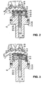
- FIGS. 2 and 3 This movement possibilities of the processing section 16 of Membrane 14 are illustrated in FIGS. 2 and 3. Located here the tool 10 with the processing section 16 the membrane 14 in engagement with the optical to be processed effective area F of a spectacle lens L, which is a toric Has geometry.
- the lens L is on a block piece 86 blocked, as known from the German standard DIN 58766 is.
- Fig. 3 were compared with FIG. 2, only the block piece 86 with the lens L and the tool 10 in the same direction 90 ° further rotated about their respective axis, without any movement of the entire tool 10 and the block piece 86 in vertical or horizontal direction, and also without Pivoting movement between spectacle lens L and tool 10.
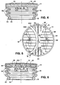
- FIGS. 4 to 6 show membranes 14 for a second and third, respectively Embodiment of the tool 10, the following only should be described in so far as they are by reference to the first embodiment described in FIGS. 1 to 3 differ.
- the rest of the structure of the tool 10 according to the second and third embodiments not further from the structure of the tool 10 according to the first embodiment was distinguished, was on a re-presentation the other parts (base body 12, guide member 24, etc.) waived.
- Reinforcement 88 is here by a plastically deformable, metallic sheet metal section formed, which preferably consists of a TiZn alloy.
- the processing section 16 of Membrane 14 such that the processing section 16 is not so yielding is that he is also interested in long-wave kinematic Roughnecks can adjust how they can arise when the Pre-processing of the lenses L by turning or milling rather, is sufficiently rigid to these roughnesses to smooth.
- the reinforcement 88 is due to their plastic Deformability in the position, the machining section 16 according to the respective processing requirements to give preselectable geometry, with the reinforcement 88 in turn due to their inherent stiffness prevents the machining section 16, due to its training of an elastomer a memory has its geometry pretending.
- the reinforcement 88 In addition, especially for the finishing of non-rotationally symmetric, especially toric surfaces F, by moving in two perpendicular planes different bending stiffnesses were given. That was here, as shown in Fig. 5, by a cross-shaped arrangement of four sets of sentences, each substantially parallel extending slots 90, 92 accomplished, extending from the edge 94 of the reinforcement 88 extend inwards and there at a slot-free portion 96 of the reinforcement 88, the substantially the shape of a "X" curved inwards on both sides having.
- the slots 90 of each set of slots 90 bounded at its inner end by an imaginary arc K90 (shown in Fig.
- a reinforcement 88 provided in the embodiment of FIG. 6 .
- the membrane 14 according to this embodiment an elastic intermediate layer 98, the on the side facing away from the pressure medium chamber 20 side of the processing section 16 above the reinforcement 88 on the processing section 16 of the membrane 14 by means of a suitable adhesive is attached and has the same outer diameter like the processing section 16.
- the intermediate layer 98 here consists of a polyurethane (polyurethane) foam (e.g. Aclacell® from the Aclawerken) and has a Shore A hardness from 35 to 60, preferably from 45 to 50.
- This intermediate layer 98 is primarily for the finishing of Free form surfaces provided, so that these transitions between Surface areas of different geometry clean can be polished out.
- FIG. 6 shows a thin layer 100 between the intermediate layer 98 and the polishing agent carrier 58.
- This layer 100 made of a rubber material with a hardness to Shore A of about 60 to 70 and again by means of a suitable adhesive is attached, serves the adhesion between intermediate layer 98 and polish carrier 58.
- One on the body longitudinally displaceable Guided guide member is connected to the processing section of Actively connected membrane, so that the processing section in Longitudinal direction of the guide member movable and in the transverse direction held to the guide member, however, under an elastic Deformation of the bellows section tiltable with respect to the Guiding member is.
- a simply trained and reliably working tool created that a very good adaptability to a wide range of machinable Has geometries.
Applications Claiming Priority (2)
| Application Number | Priority Date | Filing Date | Title |
|---|---|---|---|
| DE10319945 | 2003-05-02 | ||
| DE10319945A DE10319945A1 (de) | 2003-05-02 | 2003-05-02 | Werkzeug zur Feinbearbeitung von optisch wirksamen Flächen |
Publications (2)
| Publication Number | Publication Date |
|---|---|
| EP1473116A1 true EP1473116A1 (fr) | 2004-11-03 |
| EP1473116B1 EP1473116B1 (fr) | 2005-10-12 |
Family
ID=32981216
Family Applications (1)
| Application Number | Title | Priority Date | Filing Date |
|---|---|---|---|
| EP04006179A Expired - Lifetime EP1473116B1 (fr) | 2003-05-02 | 2004-03-16 | Outil de finissage de surfaces optiques |
Country Status (5)
| Country | Link |
|---|---|
| US (1) | US7066794B2 (fr) |
| EP (1) | EP1473116B1 (fr) |
| AT (1) | ATE306359T1 (fr) |
| DE (2) | DE10319945A1 (fr) |
| ES (1) | ES2250935T3 (fr) |
Cited By (21)
| Publication number | Priority date | Publication date | Assignee | Title |
|---|---|---|---|---|
| DE102004062319B3 (de) * | 2004-12-20 | 2006-03-02 | Schneider Gmbh + Co. Kg | Polierwerkzeug |
| EP1652619A2 (fr) * | 2004-10-29 | 2006-05-03 | Schneider GmbH + Co. KG | Outil de polissage à plusieurs zones de pression |
| DE102007026841A1 (de) | 2007-06-06 | 2008-12-11 | Satisloh Ag | Polierteller für ein Werkzeug zur Feinbearbeitung von optisch wirksamen Flächen an insbesondere Brillengläsern und Verfahren für dessen Herstellung |
| EP2093018A1 (fr) | 2008-02-25 | 2009-08-26 | Satisloh AG | Pièce de bloc pour maintenir une pièce de travail optique, en particulier un verre de lunette, pour traitement associé, et procédé de fabrication de verres de lunettes selon une prescription |
| EP2138271A1 (fr) | 2008-06-26 | 2009-12-30 | Satisloh AG | Procédé de fabrication de lentilles correctrices sur ordonnance |
| DE102009036981A1 (de) | 2009-08-12 | 2011-02-17 | Satisloh Ag | Flexibles Polierwerkzeug zur Feinbearbeitung von optisch wirksamen Flächen an insbesondere Brillengläsern |
| EP2298498A2 (fr) | 2009-09-16 | 2011-03-23 | Satisloh AG | Dispositif de traitement précis de surfaces à effet optique, notamment sur des verres de lunettes |
| EP2308644A2 (fr) | 2009-10-08 | 2011-04-13 | Satisloh AG | Dispositif de traitement précis de surfaces optiquement actif sur des pièces usinées, en particulier sur des lentilles ophtalmiques |
| DE102011014230A1 (de) | 2011-03-17 | 2012-09-20 | Satisloh Ag | Vorrichtung zur Feinbearbeitung von optisch wirksamen Flächen an insbesondere Brillengläsern |
| DE102011015458A1 (de) * | 2011-03-25 | 2012-09-27 | Schneider Gmbh & Co. Kg | Poliervorrichtung mit Drehdurchführung |
| FR2980386A1 (fr) * | 2011-09-27 | 2013-03-29 | Visioptimum Internat | Dispositif de polissage de lentilles optiques |
| EP2801440A1 (fr) | 2013-05-06 | 2014-11-12 | Satisloh AG | Pièce de blocage à multiples materiaux et procédé utilisant la pièce de blocage |
| EP2826592A1 (fr) | 2013-05-06 | 2015-01-21 | Satisloh AG | Pièce de blocage à parties multiples |
| EP2963458A1 (fr) | 2014-07-05 | 2016-01-06 | Satisloh AG | Ébauche de lentille comportant un revêtement de préhension temporaire pour un procédé de verres de lunettes selon une prescription |
| EP3009230A1 (fr) | 2014-10-15 | 2016-04-20 | Satisloh AG | Unité de blocage pour une pièce de blocage pour un verre de lunettes et procédé de durcissement |
| EP3124175A2 (fr) | 2015-07-31 | 2017-02-01 | Satisloh AG | Procede de traitement de pieces usinees optiques, en particulier lentilles de lunette en matiere plastique |
| EP3418000A1 (fr) * | 2017-06-19 | 2018-12-26 | Schneider GmbH & Co. KG | Porte-outil et dispositif de polissage de lentilles |
| EP3479912A1 (fr) | 2017-11-07 | 2019-05-08 | Satisloh AG | Station de nettoyage pour des éléments optiques |
| EP3542956A1 (fr) | 2018-03-23 | 2019-09-25 | Carl Zeiss Vision International GmbH | Procédé de fabrication de lentilles de lunettes selon une ordonnance |
| WO2023046937A1 (fr) | 2021-09-24 | 2023-03-30 | Satisloh Ag | Procédé d'usinage de pièces optiques, en particulier de verres de lunettes en matière plastique |
| DE102021005202A1 (de) | 2021-10-19 | 2023-04-20 | Satisloh Ag | Aufnahme für die Bearbeitung von optischen Werkstücken, insbesondere Brillenlinsen |
Families Citing this family (13)
| Publication number | Priority date | Publication date | Assignee | Title |
|---|---|---|---|---|
| US7988534B1 (en) * | 2004-05-19 | 2011-08-02 | Sutton Stephen P | Optical polishing pitch formulations |
| EP1655102B1 (fr) * | 2004-11-09 | 2008-01-09 | Seiko Epson Corporation | Outil de polissage élastique et méthode de polissage d'une lentille utilisant cet outil |
| DE102005010583A1 (de) * | 2005-03-04 | 2006-09-07 | Satisloh Gmbh | Polierteller für ein Werkzeug zur Feinbearbeitung von optisch wirksamen Flächen an insbesondere Brillengläsern |
| TWI292731B (en) * | 2005-03-08 | 2008-01-21 | Nat Applied Res Laboratories | Polishing apparatus and method |
| DE102007001133B4 (de) * | 2007-01-05 | 2008-09-04 | Mdi Schott Advanced Processing Gmbh | Verfahren und Vorrichtung zum Brechen von Dünnglasscheiben |
| DE102007042667A1 (de) * | 2007-09-10 | 2009-03-12 | Schneider Gmbh & Co. Kg | Poliermaschine für Linsen und Verfahren zum Polieren einer Linse mit einer Bearbeitungsmaschine |
| US20130017325A1 (en) * | 2009-08-31 | 2013-01-17 | Hoya Corporation | Polarizing element and method for manufacturing polarizing lens |
| US20160008944A1 (en) * | 2013-03-19 | 2016-01-14 | Jun Zha | Polishing device for optical elements and method thereof |
| CN103600276B (zh) * | 2013-05-20 | 2018-02-02 | 杨斌堂 | 可控变形软刀具 |
| DE102013220973A1 (de) * | 2013-10-16 | 2015-04-16 | Carl Zeiss Vision International Gmbh | Werkzeug zur Polierbearbeitung von optischen Flächen |
| MX368711B (es) * | 2013-11-27 | 2019-10-11 | Essilor Int | Soporte de bloqueo neumatico de un lente optico. |
| WO2017165215A2 (fr) * | 2016-03-24 | 2017-09-28 | 3M Innovative Properties Company | Appareil à forme façonnable |
| DE102019005084A1 (de) * | 2019-07-16 | 2021-01-21 | Schneider Gmbh & Co. Kg | Polierwerkzeug sowie Vorrichtung zum Polieren eines Werkstücks |
Citations (3)
| Publication number | Priority date | Publication date | Assignee | Title |
|---|---|---|---|---|
| DE4214266A1 (de) * | 1992-05-01 | 1993-11-04 | Loh Engineering Ag Oensingen | Vorrichtung zur fuehrung eines werkstuecks oder werkzeugs bei der bearbeitung torischer oder sphaerischer flaechen optischer linsen auf schleif- oder poliermaschinen |
| DE4442181C1 (de) * | 1994-11-26 | 1995-10-26 | Loh Optikmaschinen Ag | Werkzeug zur Feinbearbeitung optischer Flächen |
| WO2000000324A1 (fr) * | 1998-06-29 | 2000-01-06 | Delamare Sovra | Dispositif de polissoir |
Family Cites Families (7)
| Publication number | Priority date | Publication date | Assignee | Title |
|---|---|---|---|---|
| DE3643914A1 (de) * | 1986-12-22 | 1988-06-30 | Zeiss Carl Fa | Verfahren und vorrichtung zum laeppen bzw. polieren optischer flaechen |
| US5255474A (en) * | 1990-08-06 | 1993-10-26 | Matsushita Electric Industrial Co., Ltd. | Polishing spindle |
| US5928063A (en) * | 1996-05-03 | 1999-07-27 | Coburn Optical Industries, Inc. | Pneumatically assisted unidirectional arcuate diaphragm conformal tool |
| DE50101982D1 (de) * | 2000-02-03 | 2004-05-19 | Zeiss Carl | Polierkopf für eine poliermaschine |
| DE10106007B4 (de) * | 2001-02-09 | 2007-06-14 | Optotech Optikmaschinen Gmbh | Vorrichtung zum Polieren von Linsen |
| DE10106659A1 (de) * | 2001-02-12 | 2002-08-14 | Schneider Gmbh & Co Kg | Linsenpoliermaschine |
| ATE555875T1 (de) * | 2002-01-09 | 2012-05-15 | Hoya Corp | Poierverfahren |
-
2003
- 2003-05-02 DE DE10319945A patent/DE10319945A1/de not_active Withdrawn
-
2004
- 2004-03-16 DE DE502004000096T patent/DE502004000096D1/de not_active Expired - Lifetime
- 2004-03-16 EP EP04006179A patent/EP1473116B1/fr not_active Expired - Lifetime
- 2004-03-16 ES ES04006179T patent/ES2250935T3/es not_active Expired - Lifetime
- 2004-03-16 AT AT04006179T patent/ATE306359T1/de not_active IP Right Cessation
- 2004-04-29 US US10/834,720 patent/US7066794B2/en active Active
Patent Citations (3)
| Publication number | Priority date | Publication date | Assignee | Title |
|---|---|---|---|---|
| DE4214266A1 (de) * | 1992-05-01 | 1993-11-04 | Loh Engineering Ag Oensingen | Vorrichtung zur fuehrung eines werkstuecks oder werkzeugs bei der bearbeitung torischer oder sphaerischer flaechen optischer linsen auf schleif- oder poliermaschinen |
| DE4442181C1 (de) * | 1994-11-26 | 1995-10-26 | Loh Optikmaschinen Ag | Werkzeug zur Feinbearbeitung optischer Flächen |
| WO2000000324A1 (fr) * | 1998-06-29 | 2000-01-06 | Delamare Sovra | Dispositif de polissoir |
Cited By (44)
| Publication number | Priority date | Publication date | Assignee | Title |
|---|---|---|---|---|
| EP1652619A2 (fr) * | 2004-10-29 | 2006-05-03 | Schneider GmbH + Co. KG | Outil de polissage à plusieurs zones de pression |
| EP1652619A3 (fr) * | 2004-10-29 | 2006-06-07 | Schneider GmbH + Co. KG | Outil de polissage à plusieurs zones de pression |
| DE102004062319B3 (de) * | 2004-12-20 | 2006-03-02 | Schneider Gmbh + Co. Kg | Polierwerkzeug |
| DE102007026841A1 (de) | 2007-06-06 | 2008-12-11 | Satisloh Ag | Polierteller für ein Werkzeug zur Feinbearbeitung von optisch wirksamen Flächen an insbesondere Brillengläsern und Verfahren für dessen Herstellung |
| EP2014412A1 (fr) | 2007-06-06 | 2009-01-14 | Satisloh AG | Disque à polir pour un outil destiné au traitement précis de surfaces optiques actives en particulier sur des verres de lunettes et son procédé de fabrication |
| WO2009106296A1 (fr) | 2008-02-25 | 2009-09-03 | Satisloh Ag | Pièce de blocage destinée à maintenir une pièce optique à usiner, notamment un verre de lunettes, à des fins de traitement, et procédé destiné à fabriquer un verre de lunettes conformément à une prescription |
| EP2266753A1 (fr) | 2008-02-25 | 2010-12-29 | Satisloh AG | Pièce de bloc pour maintenir une pièce de travail optique, en particulier un verre de lunette, pour traitement associé, et procédé de fabrication de verres de lunettes selon une prescription |
| EP2093018A1 (fr) | 2008-02-25 | 2009-08-26 | Satisloh AG | Pièce de bloc pour maintenir une pièce de travail optique, en particulier un verre de lunette, pour traitement associé, et procédé de fabrication de verres de lunettes selon une prescription |
| EP2138271A1 (fr) | 2008-06-26 | 2009-12-30 | Satisloh AG | Procédé de fabrication de lentilles correctrices sur ordonnance |
| CN102574262A (zh) * | 2009-08-12 | 2012-07-11 | 萨特隆股份公司 | 对尤其是眼镜镜片的光学有效表面进行精加工的抛光工具 |
| DE102009036981A1 (de) | 2009-08-12 | 2011-02-17 | Satisloh Ag | Flexibles Polierwerkzeug zur Feinbearbeitung von optisch wirksamen Flächen an insbesondere Brillengläsern |
| WO2011018212A1 (fr) | 2009-08-12 | 2011-02-17 | Satisloh Ag | Polissoir pour la finition de surfaces optiquement actives en particulier de verres de lunettes |
| CN102574262B (zh) * | 2009-08-12 | 2014-06-04 | 萨特隆股份公司 | 对尤其是眼镜镜片的光学有效表面进行精加工的抛光工具 |
| DE202009018907U1 (de) | 2009-08-12 | 2014-05-15 | Satisloh Ag | Flexibles Polierwerkzeug zur Feinbearbeitung von optisch wirksamen Flächen an insbesondere Brillengläsern |
| EP2298498A2 (fr) | 2009-09-16 | 2011-03-23 | Satisloh AG | Dispositif de traitement précis de surfaces à effet optique, notamment sur des verres de lunettes |
| DE102009041442A1 (de) | 2009-09-16 | 2011-03-24 | Satisloh Ag | Vorrichtung zur Feinbearbeitung von optisch wirksamen Flächen an insbesondere Brillengläsern |
| EP2308644A2 (fr) | 2009-10-08 | 2011-04-13 | Satisloh AG | Dispositif de traitement précis de surfaces optiquement actif sur des pièces usinées, en particulier sur des lentilles ophtalmiques |
| DE102009048757A1 (de) | 2009-10-08 | 2011-04-14 | Satisloh Ag | Vorrichtung zur Feinbearbeitung von optisch wirksamen Flächen an Werkstücken, insbesondere Brillengläsern |
| DE102011014230A1 (de) | 2011-03-17 | 2012-09-20 | Satisloh Ag | Vorrichtung zur Feinbearbeitung von optisch wirksamen Flächen an insbesondere Brillengläsern |
| WO2012123120A1 (fr) | 2011-03-17 | 2012-09-20 | Satisloh Ag | Dispositif d'usinage de précision de surfaces à effet optique, notamment sur des verres de lunettes |
| US9079285B2 (en) | 2011-03-25 | 2015-07-14 | Scheider Gmbh & Co. Kg | Polishing device with rotary transmission leadthrough |
| DE102011015458A1 (de) * | 2011-03-25 | 2012-09-27 | Schneider Gmbh & Co. Kg | Poliervorrichtung mit Drehdurchführung |
| FR2980386A1 (fr) * | 2011-09-27 | 2013-03-29 | Visioptimum Internat | Dispositif de polissage de lentilles optiques |
| WO2013045795A1 (fr) * | 2011-09-27 | 2013-04-04 | Visioptimum International | Dispositif de polissage de lentilles optiques |
| US9764441B2 (en) | 2011-09-27 | 2017-09-19 | Visioptimum International | Device for polishing optical lenses |
| EP2801440A1 (fr) | 2013-05-06 | 2014-11-12 | Satisloh AG | Pièce de blocage à multiples materiaux et procédé utilisant la pièce de blocage |
| EP2826592A1 (fr) | 2013-05-06 | 2015-01-21 | Satisloh AG | Pièce de blocage à parties multiples |
| DE202014009911U1 (de) | 2013-05-06 | 2015-01-16 | Satisloh Ag | Multimaterial Blockstück |
| EP2963458A1 (fr) | 2014-07-05 | 2016-01-06 | Satisloh AG | Ébauche de lentille comportant un revêtement de préhension temporaire pour un procédé de verres de lunettes selon une prescription |
| EP3009230A1 (fr) | 2014-10-15 | 2016-04-20 | Satisloh AG | Unité de blocage pour une pièce de blocage pour un verre de lunettes et procédé de durcissement |
| US10259096B2 (en) | 2014-10-15 | 2019-04-16 | Satisloh Ag | Blocking unit for a block piece for a spectacle lens and process of curing |
| EP3124175A2 (fr) | 2015-07-31 | 2017-02-01 | Satisloh AG | Procede de traitement de pieces usinees optiques, en particulier lentilles de lunette en matiere plastique |
| DE102015009973A1 (de) | 2015-07-31 | 2017-02-02 | Satisloh Ag | Verfahren zur Bearbeitung von optischen Werkstücken, insbesondere Brillenlinsen aus Kunststoff |
| EP3418000A1 (fr) * | 2017-06-19 | 2018-12-26 | Schneider GmbH & Co. KG | Porte-outil et dispositif de polissage de lentilles |
| CN109129106A (zh) * | 2017-06-19 | 2019-01-04 | 施耐德两合公司 | 刀具容纳部和用于抛光光学构件的设备 |
| CN109129106B (zh) * | 2017-06-19 | 2022-04-12 | 施耐德两合公司 | 刀具容纳部和用于抛光光学构件的设备 |
| EP3479912A1 (fr) | 2017-11-07 | 2019-05-08 | Satisloh AG | Station de nettoyage pour des éléments optiques |
| WO2019091925A1 (fr) | 2017-11-07 | 2019-05-16 | Satisloh Ag | Station de nettoyage pour éléments optiques |
| EP3542956A1 (fr) | 2018-03-23 | 2019-09-25 | Carl Zeiss Vision International GmbH | Procédé de fabrication de lentilles de lunettes selon une ordonnance |
| WO2019179660A1 (fr) | 2018-03-23 | 2019-09-26 | Carl Zeiss Vision International Gmbh | Procédé de fabrication de verres à lunettes suivant une ordonnance |
| WO2023046937A1 (fr) | 2021-09-24 | 2023-03-30 | Satisloh Ag | Procédé d'usinage de pièces optiques, en particulier de verres de lunettes en matière plastique |
| DE102021004831A1 (de) | 2021-09-24 | 2023-03-30 | Satisloh Ag | Verfahren zur spanenden bearbeitung von optischen werkstücken, insbesondere brillenlinsen aus kunststoff |
| DE102021005202A1 (de) | 2021-10-19 | 2023-04-20 | Satisloh Ag | Aufnahme für die Bearbeitung von optischen Werkstücken, insbesondere Brillenlinsen |
| WO2023066824A1 (fr) | 2021-10-19 | 2023-04-27 | Satisloh Ag | Dispositif de retenue en vue du traitement de pièces optiques à travailler, en particulier de verres de lunettes |
Also Published As
| Publication number | Publication date |
|---|---|
| US7066794B2 (en) | 2006-06-27 |
| ES2250935T3 (es) | 2006-04-16 |
| US20040224619A1 (en) | 2004-11-11 |
| EP1473116B1 (fr) | 2005-10-12 |
| ATE306359T1 (de) | 2005-10-15 |
| DE502004000096D1 (de) | 2005-11-17 |
| DE10319945A1 (de) | 2005-01-27 |
Similar Documents
| Publication | Publication Date | Title |
|---|---|---|
| EP1473116B1 (fr) | Outil de finissage de surfaces optiques | |
| EP1698432B1 (fr) | Disque de polissage pour outil de finition de surfaces optiques en particulier de verres de lunettes | |
| EP3206837B1 (fr) | Disque à polir pour un outil destiné au traitement précis de surfaces optiques actives en particulier sur des verres de lunettes | |
| EP3442746B1 (fr) | Broche d'outil pour un dispositif de finition de surfaces optiquement actives sur des pièces | |
| EP2014412B1 (fr) | Disque à polir pour un outil destiné au traitement précis de surfaces optiques actives en particulier sur des verres de lunettes et son procédé de fabrication | |
| DE4214266C2 (fr) | ||
| DE2252503A1 (de) | Aufnahmefutter fuer optische linsen | |
| EP1652619A2 (fr) | Outil de polissage à plusieurs zones de pression | |
| EP1711311A1 (fr) | Dispositif et procede pour polir une surface optique, composant optique, et procede pour realiser un outil de polissage | |
| DE102007040395B4 (de) | Vorrichtung zur blockfreien Fertigung von Ein- und Mehrstärkengläsern in der Rezeptfertigung | |
| EP1422005B1 (fr) | Procédé et dispositif pour l'usinage du bord de lentilles ophtalmiques en plastique | |
| EP3463751A1 (fr) | Outil, dispositif et procédé de polissage de lentilles | |
| DE10031057B4 (de) | Verfahren und Vorrichtung zum korrigierenden Feinstpolieren von vorbearbeiteten optischen Linsen und Spiegeln | |
| DE10106007B4 (de) | Vorrichtung zum Polieren von Linsen | |
| EP2384854A2 (fr) | Outil de polissage pour le traitement de surfaces optiques, notamment des surfaces de moulage libre | |
| DE102007050470A1 (de) | Verfahren zum Herstellen von optisch aktiven Oberflächen durch Polieren von vorgeschliffenen Linsen und eine Vorrichtung zur Durchführung des Verfahrens | |
| DE102008061267A1 (de) | Poliervorrichtung mit Drehdurchführung | |
| EP3126091B1 (fr) | Outil de polissage ainsi que dispositif et procédé de polissage de surface de verres de lunettes optimisé en termes de défauts de moulage et coques de moulage pour fabriquer des verres de lunettes | |
| DE2811446A1 (de) | Adapter fuer ein werkzeug zur oberflaechenbehandlung von linsen | |
| DE102004016445B4 (de) | Vorrichtung zum Halten von Brillengläsern und anderen Formkörpern mit optisch wirksamen Oberflächen beim Bearbeiten | |
| DE19926414A1 (de) | Kombiwerkzeug zum Bearbeiten optischer Linsen | |
| DE10013649A1 (de) | Zusatzschleifwerkzeug an einer Brillenglasrandschleifmaschine | |
| DE102011015458A1 (de) | Poliervorrichtung mit Drehdurchführung | |
| DE19949882A1 (de) | Polierwerkzeug | |
| DD138042B1 (de) | Verfahren und vorrichtung zum herstellen von hinterdrehungen in bohrungen |
Legal Events
| Date | Code | Title | Description |
|---|---|---|---|
| PUAI | Public reference made under article 153(3) epc to a published international application that has entered the european phase |
Free format text: ORIGINAL CODE: 0009012 |
|
| AK | Designated contracting states |
Kind code of ref document: A1 Designated state(s): AT BE BG CH CY CZ DE DK EE ES FI FR GB GR HU IE IT LI LU MC NL PL PT RO SE SI SK TR |
|
| AX | Request for extension of the european patent |
Extension state: AL LT LV MK |
|
| 17P | Request for examination filed |
Effective date: 20040914 |
|
| GRAP | Despatch of communication of intention to grant a patent |
Free format text: ORIGINAL CODE: EPIDOSNIGR1 |
|
| AKX | Designation fees paid |
Designated state(s): AT BE BG CH CY CZ DE DK EE ES FI FR GB GR HU IE IT LI LU MC NL PL PT RO SE SI SK TR |
|
| GRAS | Grant fee paid |
Free format text: ORIGINAL CODE: EPIDOSNIGR3 |
|
| GRAA | (expected) grant |
Free format text: ORIGINAL CODE: 0009210 |
|
| RAP1 | Party data changed (applicant data changed or rights of an application transferred) |
Owner name: SATISLOH GMBH |
|
| AK | Designated contracting states |
Kind code of ref document: B1 Designated state(s): AT BE BG CH CY CZ DE DK EE ES FI FR GB GR HU IE IT LI LU MC NL PL PT RO SE SI SK TR |
|
| PG25 | Lapsed in a contracting state [announced via postgrant information from national office to epo] |
Ref country code: RO Free format text: LAPSE BECAUSE OF FAILURE TO SUBMIT A TRANSLATION OF THE DESCRIPTION OR TO PAY THE FEE WITHIN THE PRESCRIBED TIME-LIMIT Effective date: 20051012 Ref country code: FI Free format text: LAPSE BECAUSE OF FAILURE TO SUBMIT A TRANSLATION OF THE DESCRIPTION OR TO PAY THE FEE WITHIN THE PRESCRIBED TIME-LIMIT Effective date: 20051012 Ref country code: CZ Free format text: LAPSE BECAUSE OF FAILURE TO SUBMIT A TRANSLATION OF THE DESCRIPTION OR TO PAY THE FEE WITHIN THE PRESCRIBED TIME-LIMIT Effective date: 20051012 Ref country code: IE Free format text: LAPSE BECAUSE OF FAILURE TO SUBMIT A TRANSLATION OF THE DESCRIPTION OR TO PAY THE FEE WITHIN THE PRESCRIBED TIME-LIMIT Effective date: 20051012 Ref country code: SI Free format text: LAPSE BECAUSE OF FAILURE TO SUBMIT A TRANSLATION OF THE DESCRIPTION OR TO PAY THE FEE WITHIN THE PRESCRIBED TIME-LIMIT Effective date: 20051012 Ref country code: NL Free format text: LAPSE BECAUSE OF FAILURE TO SUBMIT A TRANSLATION OF THE DESCRIPTION OR TO PAY THE FEE WITHIN THE PRESCRIBED TIME-LIMIT Effective date: 20051012 Ref country code: PL Free format text: LAPSE BECAUSE OF FAILURE TO SUBMIT A TRANSLATION OF THE DESCRIPTION OR TO PAY THE FEE WITHIN THE PRESCRIBED TIME-LIMIT Effective date: 20051012 Ref country code: SK Free format text: LAPSE BECAUSE OF FAILURE TO SUBMIT A TRANSLATION OF THE DESCRIPTION OR TO PAY THE FEE WITHIN THE PRESCRIBED TIME-LIMIT Effective date: 20051012 |
|
| REG | Reference to a national code |
Ref country code: GB Ref legal event code: FG4D Free format text: NOT ENGLISH |
|
| REG | Reference to a national code |
Ref country code: CH Ref legal event code: EP |
|
| REG | Reference to a national code |
Ref country code: IE Ref legal event code: FG4D Free format text: LANGUAGE OF EP DOCUMENT: GERMAN |
|
| REF | Corresponds to: |
Ref document number: 502004000096 Country of ref document: DE Date of ref document: 20051117 Kind code of ref document: P |
|
| PG25 | Lapsed in a contracting state [announced via postgrant information from national office to epo] |
Ref country code: GR Free format text: LAPSE BECAUSE OF FAILURE TO SUBMIT A TRANSLATION OF THE DESCRIPTION OR TO PAY THE FEE WITHIN THE PRESCRIBED TIME-LIMIT Effective date: 20060112 Ref country code: SE Free format text: LAPSE BECAUSE OF FAILURE TO SUBMIT A TRANSLATION OF THE DESCRIPTION OR TO PAY THE FEE WITHIN THE PRESCRIBED TIME-LIMIT Effective date: 20060112 Ref country code: BG Free format text: LAPSE BECAUSE OF FAILURE TO SUBMIT A TRANSLATION OF THE DESCRIPTION OR TO PAY THE FEE WITHIN THE PRESCRIBED TIME-LIMIT Effective date: 20060112 Ref country code: DK Free format text: LAPSE BECAUSE OF FAILURE TO SUBMIT A TRANSLATION OF THE DESCRIPTION OR TO PAY THE FEE WITHIN THE PRESCRIBED TIME-LIMIT Effective date: 20060112 |
|
| GBT | Gb: translation of ep patent filed (gb section 77(6)(a)/1977) |
Effective date: 20060120 |
|
| PG25 | Lapsed in a contracting state [announced via postgrant information from national office to epo] |
Ref country code: PT Free format text: LAPSE BECAUSE OF FAILURE TO SUBMIT A TRANSLATION OF THE DESCRIPTION OR TO PAY THE FEE WITHIN THE PRESCRIBED TIME-LIMIT Effective date: 20060313 |
|
| PG25 | Lapsed in a contracting state [announced via postgrant information from national office to epo] |
Ref country code: AT Free format text: LAPSE BECAUSE OF NON-PAYMENT OF DUE FEES Effective date: 20060316 |
|
| PG25 | Lapsed in a contracting state [announced via postgrant information from national office to epo] |
Ref country code: LU Free format text: LAPSE BECAUSE OF NON-PAYMENT OF DUE FEES Effective date: 20060331 Ref country code: BE Free format text: LAPSE BECAUSE OF NON-PAYMENT OF DUE FEES Effective date: 20060331 Ref country code: MC Free format text: LAPSE BECAUSE OF NON-PAYMENT OF DUE FEES Effective date: 20060331 |
|
| NLV1 | Nl: lapsed or annulled due to failure to fulfill the requirements of art. 29p and 29m of the patents act | ||
| PG25 | Lapsed in a contracting state [announced via postgrant information from national office to epo] |
Ref country code: HU Free format text: LAPSE BECAUSE OF FAILURE TO SUBMIT A TRANSLATION OF THE DESCRIPTION OR TO PAY THE FEE WITHIN THE PRESCRIBED TIME-LIMIT Effective date: 20060413 |
|
| REG | Reference to a national code |
Ref country code: ES Ref legal event code: FG2A Ref document number: 2250935 Country of ref document: ES Kind code of ref document: T3 |
|
| REG | Reference to a national code |
Ref country code: IE Ref legal event code: FD4D |
|
| ET | Fr: translation filed | ||
| PLBE | No opposition filed within time limit |
Free format text: ORIGINAL CODE: 0009261 |
|
| STAA | Information on the status of an ep patent application or granted ep patent |
Free format text: STATUS: NO OPPOSITION FILED WITHIN TIME LIMIT |
|
| 26N | No opposition filed |
Effective date: 20060713 |
|
| BERE | Be: lapsed |
Owner name: SATISLOH G.M.B.H. Effective date: 20060331 |
|
| PG25 | Lapsed in a contracting state [announced via postgrant information from national office to epo] |
Ref country code: EE Free format text: LAPSE BECAUSE OF FAILURE TO SUBMIT A TRANSLATION OF THE DESCRIPTION OR TO PAY THE FEE WITHIN THE PRESCRIBED TIME-LIMIT Effective date: 20051012 |
|
| PG25 | Lapsed in a contracting state [announced via postgrant information from national office to epo] |
Ref country code: TR Free format text: LAPSE BECAUSE OF FAILURE TO SUBMIT A TRANSLATION OF THE DESCRIPTION OR TO PAY THE FEE WITHIN THE PRESCRIBED TIME-LIMIT Effective date: 20051012 |
|
| REG | Reference to a national code |
Ref country code: CH Ref legal event code: PL |
|
| PG25 | Lapsed in a contracting state [announced via postgrant information from national office to epo] |
Ref country code: CY Free format text: LAPSE BECAUSE OF FAILURE TO SUBMIT A TRANSLATION OF THE DESCRIPTION OR TO PAY THE FEE WITHIN THE PRESCRIBED TIME-LIMIT Effective date: 20051012 |
|
| PG25 | Lapsed in a contracting state [announced via postgrant information from national office to epo] |
Ref country code: LI Free format text: LAPSE BECAUSE OF NON-PAYMENT OF DUE FEES Effective date: 20080331 Ref country code: CH Free format text: LAPSE BECAUSE OF NON-PAYMENT OF DUE FEES Effective date: 20080331 |
|
| REG | Reference to a national code |
Ref country code: FR Ref legal event code: PLFP Year of fee payment: 13 |
|
| REG | Reference to a national code |
Ref country code: FR Ref legal event code: PLFP Year of fee payment: 14 |
|
| REG | Reference to a national code |
Ref country code: FR Ref legal event code: PLFP Year of fee payment: 15 |
|
| PGFP | Annual fee paid to national office [announced via postgrant information from national office to epo] |
Ref country code: FR Payment date: 20230327 Year of fee payment: 20 |
|
| PGFP | Annual fee paid to national office [announced via postgrant information from national office to epo] |
Ref country code: IT Payment date: 20230321 Year of fee payment: 20 Ref country code: GB Payment date: 20230327 Year of fee payment: 20 Ref country code: DE Payment date: 20230329 Year of fee payment: 20 |
|
| P01 | Opt-out of the competence of the unified patent court (upc) registered |
Effective date: 20230525 |
|
| PGFP | Annual fee paid to national office [announced via postgrant information from national office to epo] |
Ref country code: ES Payment date: 20230403 Year of fee payment: 20 |
|
| REG | Reference to a national code |
Ref country code: DE Ref legal event code: R071 Ref document number: 502004000096 Country of ref document: DE |
|
| REG | Reference to a national code |
Ref country code: ES Ref legal event code: FD2A Effective date: 20240327 |
|
| REG | Reference to a national code |
Ref country code: GB Ref legal event code: PE20 Expiry date: 20240315 |
|
| PG25 | Lapsed in a contracting state [announced via postgrant information from national office to epo] |
Ref country code: ES Free format text: LAPSE BECAUSE OF EXPIRATION OF PROTECTION Effective date: 20240317 |
|
| PG25 | Lapsed in a contracting state [announced via postgrant information from national office to epo] |
Ref country code: ES Free format text: LAPSE BECAUSE OF EXPIRATION OF PROTECTION Effective date: 20240317 Ref country code: GB Free format text: LAPSE BECAUSE OF EXPIRATION OF PROTECTION Effective date: 20240315 |