EP1472385B1 - Verfahren und vorrichtung zum galvanisieren von gegenständen - Google Patents
Verfahren und vorrichtung zum galvanisieren von gegenständen Download PDFInfo
- Publication number
- EP1472385B1 EP1472385B1 EP03729565A EP03729565A EP1472385B1 EP 1472385 B1 EP1472385 B1 EP 1472385B1 EP 03729565 A EP03729565 A EP 03729565A EP 03729565 A EP03729565 A EP 03729565A EP 1472385 B1 EP1472385 B1 EP 1472385B1
- Authority
- EP
- European Patent Office
- Prior art keywords
- objects
- bath
- shot
- zinc
- blasters
- Prior art date
- Legal status (The legal status is an assumption and is not a legal conclusion. Google has not performed a legal analysis and makes no representation as to the accuracy of the status listed.)
- Expired - Lifetime
Links
- 238000000034 method Methods 0.000 title claims abstract description 32
- 238000005246 galvanizing Methods 0.000 title claims abstract description 30
- HCHKCACWOHOZIP-UHFFFAOYSA-N Zinc Chemical compound [Zn] HCHKCACWOHOZIP-UHFFFAOYSA-N 0.000 claims abstract description 49
- 239000011701 zinc Substances 0.000 claims abstract description 49
- 229910052725 zinc Inorganic materials 0.000 claims abstract description 48
- 238000005422 blasting Methods 0.000 claims abstract description 35
- 239000010410 layer Substances 0.000 claims abstract description 21
- 230000004907 flux Effects 0.000 claims abstract description 19
- 239000000463 material Substances 0.000 claims abstract description 11
- 239000002184 metal Substances 0.000 claims abstract description 10
- 229910052751 metal Inorganic materials 0.000 claims abstract description 10
- 239000002344 surface layer Substances 0.000 claims abstract description 6
- 239000000725 suspension Substances 0.000 claims description 22
- 229910000831 Steel Inorganic materials 0.000 claims description 14
- 239000010959 steel Substances 0.000 claims description 14
- 238000001816 cooling Methods 0.000 claims description 11
- 239000007788 liquid Substances 0.000 claims description 9
- 239000000126 substance Substances 0.000 claims description 6
- XLYOFNOQVPJJNP-UHFFFAOYSA-N water Substances O XLYOFNOQVPJJNP-UHFFFAOYSA-N 0.000 claims description 5
- 239000000654 additive Substances 0.000 claims description 4
- 238000004140 cleaning Methods 0.000 claims description 4
- 238000001514 detection method Methods 0.000 claims description 4
- 230000001174 ascending effect Effects 0.000 claims description 3
- 238000007664 blowing Methods 0.000 claims description 3
- 229910052799 carbon Inorganic materials 0.000 claims description 3
- 238000001035 drying Methods 0.000 claims description 3
- 239000000203 mixture Substances 0.000 claims description 3
- 229910052710 silicon Inorganic materials 0.000 claims description 3
- OKTJSMMVPCPJKN-UHFFFAOYSA-N Carbon Chemical compound [C] OKTJSMMVPCPJKN-UHFFFAOYSA-N 0.000 claims 2
- XUIMIQQOPSSXEZ-UHFFFAOYSA-N Silicon Chemical compound [Si] XUIMIQQOPSSXEZ-UHFFFAOYSA-N 0.000 claims 2
- 239000010703 silicon Substances 0.000 claims 2
- 230000008878 coupling Effects 0.000 claims 1
- 238000010168 coupling process Methods 0.000 claims 1
- 238000005859 coupling reaction Methods 0.000 claims 1
- VEXZGXHMUGYJMC-UHFFFAOYSA-N Hydrochloric acid Chemical compound Cl VEXZGXHMUGYJMC-UHFFFAOYSA-N 0.000 description 11
- XEEYBQQBJWHFJM-UHFFFAOYSA-N Iron Chemical group [Fe] XEEYBQQBJWHFJM-UHFFFAOYSA-N 0.000 description 8
- 238000006073 displacement reaction Methods 0.000 description 8
- NLXLAEXVIDQMFP-UHFFFAOYSA-N Ammonia chloride Chemical compound [NH4+].[Cl-] NLXLAEXVIDQMFP-UHFFFAOYSA-N 0.000 description 3
- XEPNJJFNSJKTSO-UHFFFAOYSA-N azanium;zinc;chloride Chemical compound [NH4+].[Cl-].[Zn] XEPNJJFNSJKTSO-UHFFFAOYSA-N 0.000 description 3
- 230000007797 corrosion Effects 0.000 description 3
- 238000005260 corrosion Methods 0.000 description 3
- 239000002245 particle Substances 0.000 description 3
- 239000007921 spray Substances 0.000 description 3
- 238000005507 spraying Methods 0.000 description 3
- 229910045601 alloy Inorganic materials 0.000 description 2
- 239000000956 alloy Substances 0.000 description 2
- 230000008859 change Effects 0.000 description 2
- 238000010276 construction Methods 0.000 description 2
- 239000000428 dust Substances 0.000 description 2
- 229910052742 iron Inorganic materials 0.000 description 2
- JEIPFZHSYJVQDO-UHFFFAOYSA-N iron(III) oxide Inorganic materials O=[Fe]O[Fe]=O JEIPFZHSYJVQDO-UHFFFAOYSA-N 0.000 description 2
- 238000010422 painting Methods 0.000 description 2
- 230000008569 process Effects 0.000 description 2
- 229910000640 Fe alloy Inorganic materials 0.000 description 1
- 229910001297 Zn alloy Inorganic materials 0.000 description 1
- 230000002411 adverse Effects 0.000 description 1
- 235000019270 ammonium chloride Nutrition 0.000 description 1
- 230000008901 benefit Effects 0.000 description 1
- 230000015572 biosynthetic process Effects 0.000 description 1
- 238000004210 cathodic protection Methods 0.000 description 1
- 238000006243 chemical reaction Methods 0.000 description 1
- 239000003795 chemical substances by application Substances 0.000 description 1
- 239000002826 coolant Substances 0.000 description 1
- 238000005238 degreasing Methods 0.000 description 1
- 238000007598 dipping method Methods 0.000 description 1
- 230000000694 effects Effects 0.000 description 1
- 230000007613 environmental effect Effects 0.000 description 1
- 238000007654 immersion Methods 0.000 description 1
- 239000012535 impurity Substances 0.000 description 1
- 230000007246 mechanism Effects 0.000 description 1
- 238000012986 modification Methods 0.000 description 1
- 230000004048 modification Effects 0.000 description 1
- 238000005554 pickling Methods 0.000 description 1
- 230000001681 protective effect Effects 0.000 description 1
- 238000011084 recovery Methods 0.000 description 1
- 238000005479 sherardizing Methods 0.000 description 1
- 239000011592 zinc chloride Substances 0.000 description 1
- JIAARYAFYJHUJI-UHFFFAOYSA-L zinc dichloride Chemical compound [Cl-].[Cl-].[Zn+2] JIAARYAFYJHUJI-UHFFFAOYSA-L 0.000 description 1
Images


Classifications
-
- B—PERFORMING OPERATIONS; TRANSPORTING
- B24—GRINDING; POLISHING
- B24C—ABRASIVE OR RELATED BLASTING WITH PARTICULATE MATERIAL
- B24C3/00—Abrasive blasting machines or devices; Plants
- B24C3/08—Abrasive blasting machines or devices; Plants essentially adapted for abrasive blasting of travelling stock or travelling workpieces
- B24C3/10—Abrasive blasting machines or devices; Plants essentially adapted for abrasive blasting of travelling stock or travelling workpieces for treating external surfaces
- B24C3/14—Apparatus using impellers
-
- C—CHEMISTRY; METALLURGY
- C23—COATING METALLIC MATERIAL; COATING MATERIAL WITH METALLIC MATERIAL; CHEMICAL SURFACE TREATMENT; DIFFUSION TREATMENT OF METALLIC MATERIAL; COATING BY VACUUM EVAPORATION, BY SPUTTERING, BY ION IMPLANTATION OR BY CHEMICAL VAPOUR DEPOSITION, IN GENERAL; INHIBITING CORROSION OF METALLIC MATERIAL OR INCRUSTATION IN GENERAL
- C23C—COATING METALLIC MATERIAL; COATING MATERIAL WITH METALLIC MATERIAL; SURFACE TREATMENT OF METALLIC MATERIAL BY DIFFUSION INTO THE SURFACE, BY CHEMICAL CONVERSION OR SUBSTITUTION; COATING BY VACUUM EVAPORATION, BY SPUTTERING, BY ION IMPLANTATION OR BY CHEMICAL VAPOUR DEPOSITION, IN GENERAL
- C23C2/00—Hot-dipping or immersion processes for applying the coating material in the molten state without affecting the shape; Apparatus therefor
- C23C2/02—Pretreatment of the material to be coated, e.g. for coating on selected surface areas
- C23C2/024—Pretreatment of the material to be coated, e.g. for coating on selected surface areas by cleaning or etching
-
- C—CHEMISTRY; METALLURGY
- C23—COATING METALLIC MATERIAL; COATING MATERIAL WITH METALLIC MATERIAL; CHEMICAL SURFACE TREATMENT; DIFFUSION TREATMENT OF METALLIC MATERIAL; COATING BY VACUUM EVAPORATION, BY SPUTTERING, BY ION IMPLANTATION OR BY CHEMICAL VAPOUR DEPOSITION, IN GENERAL; INHIBITING CORROSION OF METALLIC MATERIAL OR INCRUSTATION IN GENERAL
- C23C—COATING METALLIC MATERIAL; COATING MATERIAL WITH METALLIC MATERIAL; SURFACE TREATMENT OF METALLIC MATERIAL BY DIFFUSION INTO THE SURFACE, BY CHEMICAL CONVERSION OR SUBSTITUTION; COATING BY VACUUM EVAPORATION, BY SPUTTERING, BY ION IMPLANTATION OR BY CHEMICAL VAPOUR DEPOSITION, IN GENERAL
- C23C2/00—Hot-dipping or immersion processes for applying the coating material in the molten state without affecting the shape; Apparatus therefor
- C23C2/50—Controlling or regulating the coating processes
- C23C2/52—Controlling or regulating the coating processes with means for measuring or sensing
- C23C2/525—Speed of the substrate
-
- Y—GENERAL TAGGING OF NEW TECHNOLOGICAL DEVELOPMENTS; GENERAL TAGGING OF CROSS-SECTIONAL TECHNOLOGIES SPANNING OVER SEVERAL SECTIONS OF THE IPC; TECHNICAL SUBJECTS COVERED BY FORMER USPC CROSS-REFERENCE ART COLLECTIONS [XRACs] AND DIGESTS
- Y10—TECHNICAL SUBJECTS COVERED BY FORMER USPC
- Y10T—TECHNICAL SUBJECTS COVERED BY FORMER US CLASSIFICATION
- Y10T29/00—Metal working
- Y10T29/49—Method of mechanical manufacture
- Y10T29/4998—Combined manufacture including applying or shaping of fluent material
- Y10T29/49982—Coating
- Y10T29/49986—Subsequent to metal working
-
- Y—GENERAL TAGGING OF NEW TECHNOLOGICAL DEVELOPMENTS; GENERAL TAGGING OF CROSS-SECTIONAL TECHNOLOGIES SPANNING OVER SEVERAL SECTIONS OF THE IPC; TECHNICAL SUBJECTS COVERED BY FORMER USPC CROSS-REFERENCE ART COLLECTIONS [XRACs] AND DIGESTS
- Y10—TECHNICAL SUBJECTS COVERED BY FORMER USPC
- Y10T—TECHNICAL SUBJECTS COVERED BY FORMER US CLASSIFICATION
- Y10T29/00—Metal working
- Y10T29/51—Plural diverse manufacturing apparatus including means for metal shaping or assembling
- Y10T29/5136—Separate tool stations for selective or successive operation on work
Definitions
- the present invention relates to a method and device for galvanizing objects, in particular galvanizing metal objects, as defined in the precharacterising portions of claims 1 and 17.
- a number of techniques are known for the protection of steel constructions from the effect of corrosion.
- One known technique is hot dipping galvanizing, wherein a thin layer of zinc is applied to the object surface.
- the applied zinc layer provides the object with a cathodic protection; i.e. in the case of corrosion zinc is relinquished and thus protects the underlying metal.
- the corrosion products of zinc will moreover fill up possible damage such as scratches and the like, whereby an additional protection is obtained.
- the zinc can be deposited by electrochemical means onto the object, this being known as electrolytic galvanization.
- the zinc can be applied to the metal object by spraying zinc onto the surface of the object using spray guns (zinc-spraying), by having zinc diffuse in a drum (sherardizing) or by painting the zinc onto the object (referred to as zinc dust painting or cold-galvanizing).
- a further option for applying zinc to a metal is thermal galvanizing, wherein the object for treating is immersed in liquid zinc located in a zinc bath at temperatures between 445°C and 465°C.
- the object for treating undergoes a pretreatment in which dirt, oil and fat residues are removed from the object surface.
- a pretreatment in which dirt, oil and fat residues are removed from the object surface.
- the object is then placed in a bath with a diluted hydrochloric acid solution and pickled therein so as to remove rust and mill scale.
- a flux treatment in which the object for treating is arranged in a flux bath with for instance zinc ammonium chloride so as to later obtain a good adhesion of the zinc to the steel. If the flux is first applied and then dried, this is known as dry galvanizing.
- wet galvanizing the flux is spread over the zinc bath surface and the steel is pulled therethrough. After the treatment there is formed on the steel surface an entity of zinc/iron alloy layers.
- the object is immersed, in accordance with the known method, for some minutes in the zinc bath where the liquid zinc bonds to the steel, this over the entire surface thereof and therefore also on the inside of possible hollow structures in the object.
- the immersion a number of (gamma, delta and eta layer) alloy layers are formed through reaction of zinc with metal, while a layer of pure zinc is formed when the object is taken out of the zinc bath.
- the known method further involves a number of labour-intensive and relatively costly steps, such as the arranging of the steel in degreasing baths, pickling baths and possible dezincification baths in the case of reconditioning of steel once galvanized in the past.
- the hydrochloric acid after all only removes the mill scale from the object and further impurities remain present on the object surface. Additional processing steps are hereby necessary.
- a further drawback of the known method and device is that the use of hydrochloric acid results in brittleness of the treated metal. Subsequent galvanizing of the brittle metal will therefore produce a less smooth surface, which adversely affects the appearance of the galvanized product.
- An object of the invention is to provide an improved system and method, for treating objects with a protective material.
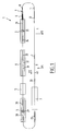
- Figures 1 and 2 show the preferred embodiment of a galvanizing device 1 according to the invention.
- the objects for galvanizing V such as for instance steel sections, are supplied and coupled at a starting position to a transport system.
- the transport system is an overhead track system and in the shown embodiment comprises a chain box rail 2 along which, using rollers 21 ( figure 2a ), a number of (for instance about 100) suspension elements 22 can be displaced at an intermediate distance of about 60 cm.
- a chain box rail system is of a conventional type per se and will not be discussed here in detail.
- Other transport systems can also be envisaged.
- the suspension elements 22 are advanced by a drive 8 connected to an electrical drive motor 9.
- Transport system 2 is provided with two tensioning elements 10 and 11 in order to place the system permanently under a determined tension.
- suspension elements 22 Once the objects for treating V have been fastened to suspension elements 22 at starting point B (arrow P 1 ), for instance by hooking the objects thereto, the suspension elements are transported in the direction of arrow P 2 .
- the untreated object V first undergoes a shot-blasting treatment in a blasting cabinet 3.
- Objects are shot-blasted in the blasting cabinet by means of a number of shot-blasters disposed at a preset angle. Not only is the blasting angle at which the objects are blasted important here, so also are the grain diameter and the material of the grains. It has been found that an optimum removal of the surface layer from the object can be achieved with the use of steel grains or other forms of steel particle with a grain thickness of between 0.25 mm and 1.6 mm, and preferably in a ratio of 40% particles with a grain size of 0.6-1.0 mm and 60% particles with a grain size of 0.8-1.3 mm.
- a good chemical composition of the grains is for instance 0.14-0.18% C, 0.65-0.85% Si and 0.35-0.55% Mn. It is possible here to opt for the removal of only the mill scale present on the object. In that case the term surface layer is understood to mean only the mill scale of the object in question. If desirable however, more layers can be removed from the object in addition to the mill scale. It is possible for instance to remove undesired unevenness from the object so that it acquires a smoother and more attractive appearance.
- flux relates to the arranging of an object in a flux bath which is for instance filled with zinc ammonium chloride.
- the fluxing agent must be substantially smoke-free, i.e. a proportionally small concentration of ammonium chloride, preferably somewhere in the order of 10% NH 4 Cl (and about 90% ZnCl 2 ), is applied.
- the zinc ammonium chloride forms a thin layer on the object which during the subsequent galvanizing process enhances the bonding of zinc to the material of the object.
- Figure 2a shows that fluxing takes place by displacing the object, hanging from a suspension element 22, through a flux bath 4.
- the object immediately after the shot-blasting and therefore before the fluxing, the object is cleaned by first of all blowing it off with air and/or then spraying it clean with water to which chemical additives have optionally been added.
- Chemical additives are added to enhance drain-off of the water with the dust which has been left behind, consisting mainly of shot-blasting dust.
- Spray cleaning takes place by arranging a number of showers along the conveyor track which remove the final iron residues resulting from the shot-blasting treatment.
- the mixture of water (optionally with additives) and iron residues is then collected and the iron is removed by applying a magnetic filter.
- the water can then be reused for spray cleaning. Owing to such a recovery, no iron residues enter the environment. Furthermore, no iron residues enter the flux bath and/or zinc bath (to be discussed later), so that these baths need changing less frequently.
- the object is guided through a zinc bath 6 ( figure 2a ) which is filled with zinc at a temperature of roughly 453°C. It has been found that at this temperature and at a transporting speed through the zinc bath in the order of magnitude of 50-250 cm per minute, and preferably 80 cm per minute, there is brought about an optimal chemical bonding of the liquid zinc to the material of the object.
- the thus formed zinc layer is of complicated structure.
- a number of alloy layers with zinc and iron in differing ratios are also formed between the zinc and the material of the object.
- the combined layer thickness of these layers varies between 50 and 150 micrometres.
- the objects After undergoing the galvanizing treatment, the objects cool through heat exchange with the environment such as outside air or heat exchange in an (optional) cooling system.
- the cooling system comprises a cooling bath 7 along which the objects can be carried.
- the objects are cooled from about 453°C to about 85°C. If one or more heat exchangers are applied, a temperature of about 80°C can be obtained.
- the cooling is carried out in a cooling bath. Separately of or combined with this cooling bath there can be provided a burnishing bath in which brightener is applied over the surface of the galvanized object in order to give the object surface a bright appearance.
- a combined coolant/brightener is preferably Karizol 2508 from the company Dipl. Ing. Herwig GmbH. Such a brightener has good cooling properties, while it also prevents so-called white rusting and makes for an attractive, highly polished product.
- the object in question After cooling and optionally being provided with brightener, the object in question is transported until it reaches end point E. Arriving here, the object can be removed from the relevant suspension element 22 and discharged (P 3 ). Since the temperature of the objects is about 85°C or less, employees can package the treated objects immediately and without problem.
- Figures 2a and 2b show a side view of a part of the device.
- the blasting and fluxing take place one immediately after the other, in contrast to the embodiment of figure 1 .
- objects V are shot-blasted with a number of blasting elements or shot-blasters 24 which are positioned such that all corners and holes in the objects can be shot-blasted. Shot-blasting therefore takes place not only on the outside but also on the inside of an internal structure of the object, to the extent at least that this internal structure can be reached from outside.
- the rail system 21 of transport system 2 has ascending and descending parts at a number of positions.
- the height of rail 21 above the floor amounts to about 2.3 m.
- the height increases from 2.3 m to about 3 m, so that shot-blasting of the objects takes place at this height.
- part 27 there is then a further rise from 3 m to about 5.3 m.
- the running time of the system i.e. the period of time between fastening of an object for treating to a suspension element and the removal of a treated object from the suspension element, amounts in the shown embodiment to about 1.5 hours, while the capacity is variable between about 3000 and 3750 kg per hour.
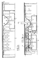
- FIG 3 shows a preferred embodiment of the blasting cabinet.
- the blasting cabinet is constructed from a casing 38 provided with an entrance opening 39 and an exit opening 40.
- the objects V can be carried inside via the entrance opening and carried out again via the exit opening.
- the form of the entrance an exit openings can be adapted to the form of the objects being treated at that moment.
- the entrance an exit openings are enlarged to for instance a width W of 60 cm, while for smaller objects the opening can be made smaller to for instance a width W of about 20 cm.
- a number of detection eyes 41 are arranged which detects the presence or absence of an object V on a suspension element 22.
- a central control (not shown) of the device can control the transport of suspension elements 22 and/or the operation of blasting cabinet 3. It is also possible to control the other elements of the system subject to the detection result, i.e. among others the flux bath 8 and the galvanizing bath (not shown). This allows (fully) automatic galvanizing of the objects.
- a number of detection eyes 42 are arranged with which can be determined the dimensions of the object which is about to enter blasting cabinet 3 at that moment.
- the gap W made available can then be adjusted depending on the dimensions of the object, for instance by sliding the sliding doors 51 and 52 relative to each other.
- Suspension element 55 comprises a number of rollers 56 and a frame 64. An object V is hung on the frame 64. Suspension element 55 is displaceable with rollers 56 along a track 63.
- the guiding consists of a beam 65 which can be guided in a slot in a component 77 of the blasting cabinet. The slot is dimensioned herein such that beam 65 is displaceable thereby in longitudinal direction, while too great a displacement in transverse direction is prevented.
- the guiding on the underside of object V comprises a first guide rail 83 and a second guide rail 84, wherein the second guide rail extends parallel to and at a mutual spacing G relative to the first guide rail.
- the choice of distance G is slightly greater here than the relevant dimension of the object (in the shown embodiment the depth of the object V).
- the distance G is usually chosen to be a maximum of 10 cm greater than the relevant dimension of the object, so that the object V can only be displaced a few centimetres in transverse direction (transverse direction P 2 ) under the influence of the blasting grains.
- the mutual spacing G between guide rails 73 and 74 can be adapted to the dimensions of object V.
- Guide rails 73,74 are arranged for this purpose on supports 75.
- Supports 75 are provided with a large number of openings 76 into which the guide rails 73,74 can be screwed fixedly.
- the shot-blasting capacity (and/or the running speed) can be adjusted.
- the shot-blasting capacity (the quantity of grains per unit of time, the blasting angles, the force with which the grains strike the objects etc.) has to be varied subject to the running speed of the transport system. This can take place for instance by making use of a frequency control mechanism.
- the suspension elements must moreover be able to change position in fully automatic manner during the displacement along the transport system, this such that the quality of the zinc layer is enhanced and the running speed is high.
- the position of the suspension hooks is adapted subject to the process an object is undergoing at a given position and a given moment in the transport system.
- the position of the suspension hooks (length about 60 cm) is adapted by providing at the correct positions in the transport system automatic rotation points which cause a suspension hook to change position as it is transported therealong.
- a conveyor track of another type is provided.
- the objects for galvanizing after a substantially horizontal displacement along the conveyor track, are moved downward substantially vertically into the flux bath, the galvanizing bath or the cooling bath. After a given time the object is once again moved substantially vertically upward, whereafter the substantially horizontal displacement of the object is continued.
- This embodiment has the advantage that the height required for the conveyor track is smaller than is the case in the previously mentioned conveyor track.
- Application of a conveyor track according to the present embodiment further means that the diverse baths require a less long form, since a horizontal displacement of the object in the relevant bath does not have to be taken into account.
- the capacity of the system can hereby increase to about 5500 kg processed material per hour.
Landscapes
- Chemical & Material Sciences (AREA)
- Engineering & Computer Science (AREA)
- Mechanical Engineering (AREA)
- Chemical Kinetics & Catalysis (AREA)
- Materials Engineering (AREA)
- Metallurgy (AREA)
- Organic Chemistry (AREA)
- Coating With Molten Metal (AREA)
- Crystals, And After-Treatments Of Crystals (AREA)
Claims (33)
- System zum thermischen Galvanisieren vorgefertigter und/oder gebrauchter Gegenstände, im Besonderen Metallobjekte (V), das aufweist:- eine obere Führungsbahn (2), die mit Hängeelementen (22) versehen ist, von denen ein Gegenstand oder mehrere Gegenstände (V) zur Behandlung aufgehängt sein können,- Antriebsmittel (8, 9) zum Fortbewegen der Hängeelemente entlang der oberen Führungsbahn,wobei sie entlang der oberen Führungsbahn wenigstens bewegt werden durch:- ein Flussmittelbad (4) zum Tauchen des durch das Bad bewegten Gegenstands in das Flussmittel;- ein Galvanisierungsbad (6) zum thermischen Galvanisieren des durch das Bad bewegten Gegenstands;dadurch gekennzeichnet, dass
entlang der oberen Laufbahn ein oder mehrere Sandstrahler (24) angeordnet sind, um ein oder mehrere Körnchenstrahlen in Richtung eines Gegenstands zu schleudern, der daran entlang bewegt wird, um wenigstens die Oberflächenschicht des Objekts zu entfernen,
und durch eine Steuerung des Antriebsmittels zur Betätigung davon für einen im Wesentlichen unterbrechungsfreien Transport der Gegenstände mit einer im Wesentlichen konstanten Laufgeschwindigkeit durch wenigstens das Bad,
und Steuermittel, die mit den Sandstrahlern und den Fortbewegungsmitteln verbunden sind, und die ausgestaltet sind, um eine geeignete Bestrahlkapazität in Abhängigkeit von der durch die Fortbewegungsmittel erzeugten Laufgeschwindigkeit anzupassen. - System gemäß Anspruch 1, wobei die Sandstrahler (24) angeordnet sind, um den Gegenstand für eine Behandlung in mehreren bestimmten Bestrahlwinkeln anzustrahlen.
- System gemäß Anspruch 1, wobei die Sandstrahler (24) ausgeführt sind, um Körnchenstrahlen mit einem durchschnittlichen Korndurchmesser zwischen 0,25 und 1,6 mm aufzuschleudern.
- System gemäß Anspruch 1, das aufweist mehrere, vorzugsweise vier, Sandstrahler (24), die an einer Seite der oberen Führungsbahn positioniert sind, und mehrere, vorzugsweise vier, Sandstrahler, die an der abgewandten Seite der oberen Führungsbahn (2) positioniert sind.
- System gemäß Anspruch 1, wobei etwa 40% der Körner eine durchschnittliche Korngröße von 0,6 - 1,0 mm und 60% der Körner eine durchschnittliche Korngröße von 0,8 -1,3 mm aufweisen.
- System gemäß Anspruch 1, wobei die Körnchen aus Stahl mit einem geringen Carbongehalt, vorzugsweise unter 0,18% Massenanteil, gefertigt sind.
- System gemäß einem der vorhergehenden Ansprüche, wobei die Verarbeitungskapazität zwischen etwa 3.000 und 3.750 kg pro Stunde variierbar ist.
- System gemäß einem der vorhergehenden Ansprüche, wobei die Sandstrahler (24) in einem Gehäuse (3) angeordnet sind, wobei die Abmessungen der Eingangs- und Ausgangsöffnungen davon gemäß der Form und den Abmessungen der Gegenstände anpassbar sind, die durch das Gehäuse bewegt werden.
- System gemäß einem der obigen Ansprüche, wobei die obere Führungsbahn (2) mit zumindest einem absteigenden und zumindest einem aufsteigenden Teil ausgeführt ist, um Gegenstände jeweils nach unten in das Bad und nach oben aus dem Bad zu befördern.
- System gemäß einem der Ansprüche 1 - 9, das aufweist Erfassungsmittel (41) zum Erfassen eines Gegenstands, der von einem der Aufhängeelemente (22) herabhängt, zusätzlich zu Steuermitteln zum Steuern der Antriebsmittel der oberen Führungsbahn und wenigstens der Sandstrahler, um den Antrieb des Aufhängeelements und der Sandstrahler mit einer bestimmten Zeitverzögerung zu unterbrechen.
- System gemäß einem der Ansprüche 1 - 10, das Mittel aufweist zum Trocknen der Gegenstände, Mittel zum Kühlen der Gegenstände und/oder Mittel zum Polieren der Gegenstände.
- System gemäß einem der Ansprüche 1 - 11, wobei Reinigungsmittel zwischen den Bestrahlmitteln und dem Flussmittelbad vorgesehen sind, um den Gegenstand mit Luft sauber zu blasen und/oder Materialreste vom Gegenstand mit einer Flüssigkeit zu entfernen.
- System gemäß Anspruch 12, Sammelmittel aufweisend zum Sammeln der Mischung aus Materialresten und Luft und/oder Flüssigkeit, Mittel zum Trennen der Materialreste und Mittel für die Zufuhr von Luft und/oder Flüssigkeit zurück in die Reinigungsmittel.
- System gemäß einem der vorhergehenden Ansprüche, wobei Mittel an einer Position über dem Galvanisierungsbad angeordnet sind, um Luft entlang des Objekts zu führen, um Zinktropfen auf dem Gegenstand wegzublasen.
- System gemäß einem der vorhergehenden Ansprüche, wobei die Sandstrahler angeordnet sind, um mehrere auf dem Gegenstand vorhandene Schichten zu entfernen.
- System gemäß Anspruch 15, wobei die Sandstrahler angeordnet sind, um den Zunder und die Silikonschicht, die auf dem Gegenstand vorhanden sind, zu entfernen.
- Verfahren zum thermischen Galvanisieren vorgefertigter und/oder gebrauchter Gegenstände, im Besonderen Metallobjekte, die Schritte aufweisend:- Verbinden der vorgefertigten und/oder gebrauchten Gegenstände (V) mit einer oberen Laufbahn (2) eines Systems gemäß einem der vorhergehenden Ansprüche;- Fortbewegen der Gegenstände (V) entlang der oberen Führungsbahn (2), währenddessen die folgenden Schritte ausgeführt werden:- Vorbehandeln des Gegenstands, einschließlich dem Entfernen der Oberflächenschicht von dem Gegenstand;- Anordnen des vorbehandelten Gegenstands in einem Flussmittelbad (5) zum Tauchen des Gegenstands in das Flussmittel;- Anordnen des in das Flussmittel getauchten Gegenstands in einem Zinkbad (6), um das Material des Gegenstands mit Zink reagieren zu lassen und eine zinkhaltige Beschichtung auf dem Objekt aufzutragen,dadurch gekennzeichnet,
dass der Schritt der Vorbehandlung das Bestrahlen des Gegenstands mit Körnern aufweist, um so wenigstens die Oberflächenschicht zu entfernen, und durch Steuern der Antriebsmittel zur Betätigung davon für einen im Wesentlichen unterbrechungsfreien Transport der Gegenstände in einer im Wesentlichen konstanten Laufgeschwindigkeit durch wenigstens das Bad, und durch Steuern der Sandstrahler und der Fortbewegungsmittel, um eine geeignete Bestrahlkapazität in Abhängigkeit von der von den Fortbewegungsmitteln erzeugten Laufgeschwindigkeit anzupassen. - Verfahren gemäß Anspruch 17, das Bestrahlen des Gegenstands in mehreren bestimmten Bestrahlwinkeln aufweisend.
- Verfahren gemäß Anspruch 17, wobei der durchschnittliche Durchmesser der Körner zwischen 0,25 und 1,6 mm liegt,
- Verfahren gemäß Anspruch 17, 18 oder 19, wobei etwa 40% der Körner eine durchschnittliche Korngröße von 0,6 - 1,0 mm und 60% der Körner eine durchschnittliche Korngröße von 0,8 -1,3 mm aufweisen.
- Verfahren gemäß einem der Ansprüche 17 - 20, wobei die Körner aus Stahl mit einem geringen Carbongehalt, vorzugsweise unter 0,18% Massenanteil, gefertigt sind.
- Verfahren gemäß einem der Ansprüche 17 - 21, das das Galvanisieren von Gegenständen mit einer Kapazität von zwischen etwa 3,000 und 3.750 kg an Gegenständen pro Stunde aufweist.
- Verfahren gemäß einem der Ansprüche 17 - 22, wobei der Schritt das Bestrahlens das Entfernen mehrerer auf dem Gegenstand vorhandener Schichten umfasst.
- Verfahren gemäß Anspruch 23, wobei der Schritt des Bestrahlens umfasst, den Zunder und die Silikonschicht, die auf dem Gegenstand vorhanden sind, zu entfernen.
- Verfahren gemäß Anspruch 17, wobei zwischen dem Schritt des Sandstrahlens und dem Schritt des Flussmitteltauchens der Gegenstand mit Luft sauber geblasen wird und/oder mit Flüssigkeit sauber gespritzt wird.
- Verfahren gemäß Anspruch 25, wobei die Flüssigkeit Wasser ist, dem vorzugsweise chemische Zusätze hinzugefügt wurden, um das Abfließen der Flüssigkeit vom Gegenstand zu verbessern.
- Verfahren gemäß einem der Ansprüche 17 - 26, wobei nach dem Schritt der Galvanisierung Luft am Gegenstand entlang geleitet wird, um die Zinktropfen auf dem Gegenstand wegzublasen.
- Verfahren gemäß Anspruch 27, das die Zufuhr der abgeblasenen Zinktropfen zurück in das Zinkbad umfasst.
- Verfahren gemäß einem der Ansprüche 17 - 28, wobei der Schritt des Anordnens des Gegenstands in wenigstens einem der Bäder aufweist, dass der Gegenstand durch das betreffende Bad bewegt wird.
- Verfahren gemäß Anspruch 18, wobei die Transportgeschwindigkeit durch das Zinkbad in der Größenordnung von 50 bis 250 cm, vorzugsweise bei 80 cm pro Minute liegt.
- Verfahren gemäß einem der Ansprüche 17 - 30, das das Trocknen des in das Flussmittel getauchten Gegenstands aufweist.
- Verfahren gemäß einem der Ansprüche 18 - 31, das das Abkühlen des mit einer Zinkbeschichtung versehenen Gegenstands aufweist.
- Verfahren gemäß einem der Ansprüche 17 - 32, das das Unterziehen des mit einer Zinkbeschichtung versehenen Gegenstands einer Polierbehandlung aufweist.
Applications Claiming Priority (7)
| Application Number | Priority Date | Filing Date | Title |
|---|---|---|---|
| NL1019751 | 2002-01-16 | ||
| NL1019751A NL1019751C1 (nl) | 2002-01-16 | 2002-01-16 | Werkwijze en inrichting voor het verzinken van voorwerpen. |
| NL1020689 | 2002-05-27 | ||
| NL1020689A NL1020689C2 (nl) | 2002-01-16 | 2002-05-27 | Werkwijze en inrichting voor het verzinken van voorwerpen. |
| NL1022066 | 2002-12-03 | ||
| NL1022066A NL1022066C2 (nl) | 2002-01-16 | 2002-12-03 | Inrichting voor het afstralen van te verzinken voorwerpen. |
| PCT/NL2003/000025 WO2003060177A1 (en) | 2002-01-16 | 2003-01-15 | Method and device for galvanizing objects |
Publications (2)
| Publication Number | Publication Date |
|---|---|
| EP1472385A1 EP1472385A1 (de) | 2004-11-03 |
| EP1472385B1 true EP1472385B1 (de) | 2008-12-10 |
Family
ID=27351252
Family Applications (1)
| Application Number | Title | Priority Date | Filing Date |
|---|---|---|---|
| EP03729565A Expired - Lifetime EP1472385B1 (de) | 2002-01-16 | 2003-01-15 | Verfahren und vorrichtung zum galvanisieren von gegenständen |
Country Status (8)
| Country | Link |
|---|---|
| US (1) | US7367105B2 (de) |
| EP (1) | EP1472385B1 (de) |
| AT (1) | ATE417137T1 (de) |
| AU (1) | AU2003235644A1 (de) |
| DE (1) | DE60325170D1 (de) |
| DK (1) | DK1472385T3 (de) |
| NL (1) | NL1022066C2 (de) |
| WO (1) | WO2003060177A1 (de) |
Families Citing this family (13)
| Publication number | Priority date | Publication date | Assignee | Title |
|---|---|---|---|---|
| NL1028044C2 (nl) * | 2005-01-17 | 2006-07-18 | Galva Solutions B V | Werkwijze en systeem voor het behandelen van voorwerpen. |
| DE102008020576B4 (de) * | 2008-04-24 | 2018-06-28 | Bodycote Wärmebehandlung GmbH | Verfahren zum Diffusionsverzinken |
| US20110183072A1 (en) * | 2010-01-28 | 2011-07-28 | Western Tube & Conduit Corporation | Hot-dip galvanization systems and methods |
| JP5720444B2 (ja) * | 2011-07-05 | 2015-05-20 | 新東工業株式会社 | ショット処理装置 |
| CN103551840B (zh) * | 2013-11-15 | 2015-08-26 | 青岛元启工业智能技术有限公司 | 一种电表挂钩自动装配方法 |
| CN103551839B (zh) * | 2013-11-15 | 2015-10-07 | 青岛元启工业智能技术有限公司 | 一种电表挂钩自动装配装置 |
| WO2016143413A1 (ja) * | 2015-03-12 | 2016-09-15 | 新東工業株式会社 | 投射材 |
| JP6213695B2 (ja) * | 2015-03-12 | 2017-10-18 | 新東工業株式会社 | 鋳物の研掃方法 |
| CN108555620B (zh) * | 2018-03-16 | 2020-04-24 | 南通通途机电制造有限公司 | 一种带装卸工位的回环式工作台移送装置 |
| CN113061826A (zh) * | 2021-03-25 | 2021-07-02 | 湘潭大学 | 一种高效热浸镀锌的装置 |
| CN113403563A (zh) * | 2021-05-18 | 2021-09-17 | 宜兴大平杆塔制造有限公司 | 一种高铁触网隧道吊柱镀锌装置及使用方法 |
| CN113969382A (zh) * | 2021-09-09 | 2022-01-25 | 精工阀门集团有限公司 | 一种具有主副阀门的双控装置及其生产工艺 |
| CN115287568B (zh) * | 2022-08-08 | 2023-10-20 | 任丘市嘉华电讯器材有限公司 | 一种电力铁附件热浸镀锌装置 |
Family Cites Families (19)
| Publication number | Priority date | Publication date | Assignee | Title |
|---|---|---|---|---|
| US2584647A (en) * | 1950-05-24 | 1952-02-05 | Webber Thomas Angus | Sandblasting machine for cleaning inlays or the like |
| US2852410A (en) * | 1954-03-16 | 1958-09-16 | Republic Steel Corp | Use of titanium article support for hot dip galvanizing apparatus |
| US3495720A (en) | 1966-04-19 | 1970-02-17 | Carborundum Co | Suspended conveyor trolley handling device |
| DE2004633A1 (de) | 1970-02-03 | 1971-08-12 | Audi NSU Auto Union AG, 8070 Ingol Stadt | Vergaser fur Brennkraftmaschinen |
| SE358838B (de) | 1971-12-01 | 1973-08-13 | Ingenjoers Fa Hebe Ab | |
| US3813817A (en) | 1972-05-22 | 1974-06-04 | Wheelabrator Frye Inc | Method and apparatus for surface treatment of work pieces |
| SU648653A1 (en) | 1976-07-19 | 1979-02-28 | Ts Kt B Respub Promy Obedineni | Device for applying hot coatings |
| CH613651A5 (en) | 1976-12-16 | 1979-10-15 | Fischer Ag Georg | Centrifugal abrasive-blasting machine for strip-shaped plastering material |
| DD200463A1 (de) * | 1981-08-10 | 1983-05-04 | Blumenthal Helmuth Dr Ing | Vorrichtung zum beschichten und strahlen von koerpern unterschiedlicher groesse,anordnung und konturern unterschiedlicher groesse, anordnung und konturen en |
| JPS6058304B2 (ja) | 1982-03-04 | 1985-12-19 | 日立金属株式会社 | 可鍛鋳鉄品の無酸処理溶融亜鉛めつき方法 |
| JPS60211058A (ja) | 1984-04-06 | 1985-10-23 | Shinko Bolt Kk | 冷間圧造成形された高力ボルトの溶融亜鉛めつき方法 |
| JPS60230971A (ja) | 1984-05-02 | 1985-11-16 | Shinko Bolt Kk | ナツトの溶融亜鉛めつき前処理方法 |
| CH670597A5 (de) | 1986-07-08 | 1989-06-30 | Fischer Ag Georg | |
| JPS6447842A (en) | 1987-08-18 | 1989-02-22 | Sumitomo Metal Ind | Production of hot-dipped galvanized steel tube |
| SU1738622A1 (ru) | 1990-05-07 | 1992-06-07 | Институт черной металлургии | Способ обработки длинномерных изделий дробью |
| JPH06115688A (ja) | 1991-08-06 | 1994-04-26 | Hitachi Ltd | メッキ用自動搬送装置 |
| MY111476A (en) | 1992-09-25 | 2000-06-30 | Tubemakers Australia | Method of manufacturing galvanised open or closed steel sections. |
| JPH06330273A (ja) | 1993-05-21 | 1994-11-29 | Sintokogio Ltd | 溶融メッキ鋼板の製造方法及びその装置 |
| JPH06346281A (ja) | 1993-06-08 | 1994-12-20 | Makoo Kk | ワーク表面処理方法 |
-
2002
- 2002-12-03 NL NL1022066A patent/NL1022066C2/nl not_active IP Right Cessation
-
2003
- 2003-01-15 EP EP03729565A patent/EP1472385B1/de not_active Expired - Lifetime
- 2003-01-15 WO PCT/NL2003/000025 patent/WO2003060177A1/en not_active Ceased
- 2003-01-15 DE DE60325170T patent/DE60325170D1/de not_active Expired - Lifetime
- 2003-01-15 DK DK03729565T patent/DK1472385T3/da active
- 2003-01-15 AU AU2003235644A patent/AU2003235644A1/en not_active Abandoned
- 2003-01-15 US US10/501,859 patent/US7367105B2/en not_active Expired - Fee Related
- 2003-01-15 AT AT03729565T patent/ATE417137T1/de not_active IP Right Cessation
Also Published As
| Publication number | Publication date |
|---|---|
| DK1472385T3 (da) | 2009-03-23 |
| US7367105B2 (en) | 2008-05-06 |
| NL1022066A1 (nl) | 2003-07-17 |
| US20050268996A1 (en) | 2005-12-08 |
| EP1472385A1 (de) | 2004-11-03 |
| NL1022066C2 (nl) | 2003-08-07 |
| ATE417137T1 (de) | 2008-12-15 |
| DE60325170D1 (de) | 2009-01-22 |
| AU2003235644A1 (en) | 2003-07-30 |
| WO2003060177A1 (en) | 2003-07-24 |
Similar Documents
| Publication | Publication Date | Title |
|---|---|---|
| EP1472385B1 (de) | Verfahren und vorrichtung zum galvanisieren von gegenständen | |
| EP1141435B1 (de) | Verfahren für ein feuerverzinkungs- und "galvannealing"-prozess in einem aluminium-haltigen zinkbad | |
| US9487844B2 (en) | Method for detaching coatings from scrap | |
| EP1285973A1 (de) | Plattierter metalldraht, herstellungsverfahren und -vorrichtung dafür | |
| KR20210021102A (ko) | 금속 코팅된 강철 스트립의 제조방법 | |
| WO1999058735A2 (en) | Method of producing hot-dip zinc coated steel sheet free of dross pick-up defects on coating and associated apparatus | |
| US7413769B2 (en) | Process for applying a metallic coating, an intermediate coated product, and a finish coated product | |
| RU2321675C2 (ru) | Способ и устройство для гальванизации объектов | |
| NL1019751C1 (nl) | Werkwijze en inrichting voor het verzinken van voorwerpen. | |
| KR20010060423A (ko) | 표면외관이 우수한 용융아연 도금강판 제조 방법 | |
| KR100905906B1 (ko) | 포트롤이 없는 용융 도금강판 제조장치 | |
| JPH0623561Y2 (ja) | ガルバニール炉内の酸化亜鉛除去装置 | |
| JPS59104462A (ja) | 片面溶融金属めつき方法 | |
| EP1836329A1 (de) | Verfahren und vorrichtung zur behandlung von objekten | |
| JPH0881749A (ja) | 鉄鋼加工品の溶融亜鉛めっき方法 | |
| JPH03150338A (ja) | 連続溶融合金化亜鉛メツキ鋼板の製造方法 | |
| JPH09507533A (ja) | 垂直面内を高速移動する連続基板を加速冷却するための装置 | |
| JPH09195028A (ja) | 溶融めっき装置 | |
| JP2003253415A (ja) | 連続溶融亜鉛めっき鋼板の製造方法および装置 | |
| JPH0754115A (ja) | 鋼帯の溶融金属めっき方法 | |
| JPH05306447A (ja) | 溶融亜鉛系めっき鋼帯のライン内搬送方法及びライン内搬送用ロール | |
| PL223439B1 (pl) | Sposób cynkowania stalowych, kształtowych elementów zimno giętych z powierzchniami trudno dostępnymi | |
| KR20030049338A (ko) | 용융아연 도금강판의 제조방법 | |
| JPS6130021B2 (de) | ||
| JPH09324208A (ja) | 溶融金属めっき鋼帯の製造方法および製造装置 |
Legal Events
| Date | Code | Title | Description |
|---|---|---|---|
| PUAI | Public reference made under article 153(3) epc to a published international application that has entered the european phase |
Free format text: ORIGINAL CODE: 0009012 |
|
| 17P | Request for examination filed |
Effective date: 20040804 |
|
| AK | Designated contracting states |
Kind code of ref document: A1 Designated state(s): AT BE BG CH CY CZ DE DK EE ES FI FR GB GR HU IE IT LI LU MC NL PT SE SI SK TR |
|
| AX | Request for extension of the european patent |
Extension state: AL LT LV MK RO |
|
| 19A | Proceedings stayed before grant |
Effective date: 20041223 |
|
| 19F | Resumption of proceedings before grant (after stay of proceedings) |
Effective date: 20051201 |
|
| RAP1 | Party data changed (applicant data changed or rights of an application transferred) |
Owner name: KENBO BEHEER B.V. |
|
| RAP1 | Party data changed (applicant data changed or rights of an application transferred) |
Owner name: GALVA SOLUTIONS B.V. |
|
| 17Q | First examination report despatched |
Effective date: 20051222 |
|
| GRAP | Despatch of communication of intention to grant a patent |
Free format text: ORIGINAL CODE: EPIDOSNIGR1 |
|
| GRAS | Grant fee paid |
Free format text: ORIGINAL CODE: EPIDOSNIGR3 |
|
| GRAA | (expected) grant |
Free format text: ORIGINAL CODE: 0009210 |
|
| AK | Designated contracting states |
Kind code of ref document: B1 Designated state(s): AT BE BG CH CY CZ DE DK EE ES FI FR GB GR HU IE IT LI LU MC NL PT SE SI SK TR |
|
| REG | Reference to a national code |
Ref country code: GB Ref legal event code: FG4D |
|
| REG | Reference to a national code |
Ref country code: CH Ref legal event code: EP |
|
| REG | Reference to a national code |
Ref country code: CH Ref legal event code: NV Representative=s name: ARNOLD & SIEDSMA AG |
|
| REG | Reference to a national code |
Ref country code: IE Ref legal event code: FG4D |
|
| REF | Corresponds to: |
Ref document number: 60325170 Country of ref document: DE Date of ref document: 20090122 Kind code of ref document: P |
|
| REG | Reference to a national code |
Ref country code: SE Ref legal event code: TRGR |
|
| REG | Reference to a national code |
Ref country code: DK Ref legal event code: T3 |
|
| PG25 | Lapsed in a contracting state [announced via postgrant information from national office to epo] |
Ref country code: SI Free format text: LAPSE BECAUSE OF FAILURE TO SUBMIT A TRANSLATION OF THE DESCRIPTION OR TO PAY THE FEE WITHIN THE PRESCRIBED TIME-LIMIT Effective date: 20081210 Ref country code: FI Free format text: LAPSE BECAUSE OF FAILURE TO SUBMIT A TRANSLATION OF THE DESCRIPTION OR TO PAY THE FEE WITHIN THE PRESCRIBED TIME-LIMIT Effective date: 20081210 |
|
| PG25 | Lapsed in a contracting state [announced via postgrant information from national office to epo] |
Ref country code: EE Free format text: LAPSE BECAUSE OF FAILURE TO SUBMIT A TRANSLATION OF THE DESCRIPTION OR TO PAY THE FEE WITHIN THE PRESCRIBED TIME-LIMIT Effective date: 20081210 Ref country code: BG Free format text: LAPSE BECAUSE OF FAILURE TO SUBMIT A TRANSLATION OF THE DESCRIPTION OR TO PAY THE FEE WITHIN THE PRESCRIBED TIME-LIMIT Effective date: 20090310 Ref country code: ES Free format text: LAPSE BECAUSE OF FAILURE TO SUBMIT A TRANSLATION OF THE DESCRIPTION OR TO PAY THE FEE WITHIN THE PRESCRIBED TIME-LIMIT Effective date: 20090321 |
|
| PG25 | Lapsed in a contracting state [announced via postgrant information from national office to epo] |
Ref country code: MC Free format text: LAPSE BECAUSE OF NON-PAYMENT OF DUE FEES Effective date: 20090131 Ref country code: AT Free format text: LAPSE BECAUSE OF FAILURE TO SUBMIT A TRANSLATION OF THE DESCRIPTION OR TO PAY THE FEE WITHIN THE PRESCRIBED TIME-LIMIT Effective date: 20081210 Ref country code: PT Free format text: LAPSE BECAUSE OF FAILURE TO SUBMIT A TRANSLATION OF THE DESCRIPTION OR TO PAY THE FEE WITHIN THE PRESCRIBED TIME-LIMIT Effective date: 20090511 Ref country code: CZ Free format text: LAPSE BECAUSE OF FAILURE TO SUBMIT A TRANSLATION OF THE DESCRIPTION OR TO PAY THE FEE WITHIN THE PRESCRIBED TIME-LIMIT Effective date: 20081210 |
|
| PG25 | Lapsed in a contracting state [announced via postgrant information from national office to epo] |
Ref country code: SK Free format text: LAPSE BECAUSE OF FAILURE TO SUBMIT A TRANSLATION OF THE DESCRIPTION OR TO PAY THE FEE WITHIN THE PRESCRIBED TIME-LIMIT Effective date: 20081210 |
|
| PLBE | No opposition filed within time limit |
Free format text: ORIGINAL CODE: 0009261 |
|
| STAA | Information on the status of an ep patent application or granted ep patent |
Free format text: STATUS: NO OPPOSITION FILED WITHIN TIME LIMIT |
|
| 26N | No opposition filed |
Effective date: 20090911 |
|
| REG | Reference to a national code |
Ref country code: CH Ref legal event code: PUE Owner name: ENNEMER SCHAGEN INDUSTRIES B.V. Free format text: GALVA SOLUTIONS B.V.#RONDVEN 44#6026 PX MAARHEEZE (NL) -TRANSFER TO- KENNEMER SCHAGEN INDUSTRIES B.V.#LAGEDIJKERWEG 15#1742 NB SCHAGEN (NL) |
|
| REG | Reference to a national code |
Ref country code: NL Ref legal event code: SD Effective date: 20100408 |
|
| REG | Reference to a national code |
Ref country code: GB Ref legal event code: 732E Free format text: REGISTERED BETWEEN 20100506 AND 20100512 |
|
| REG | Reference to a national code |
Ref country code: FR Ref legal event code: TP |
|
| PG25 | Lapsed in a contracting state [announced via postgrant information from national office to epo] |
Ref country code: GR Free format text: LAPSE BECAUSE OF FAILURE TO SUBMIT A TRANSLATION OF THE DESCRIPTION OR TO PAY THE FEE WITHIN THE PRESCRIBED TIME-LIMIT Effective date: 20090311 |
|
| PG25 | Lapsed in a contracting state [announced via postgrant information from national office to epo] |
Ref country code: IT Free format text: LAPSE BECAUSE OF FAILURE TO SUBMIT A TRANSLATION OF THE DESCRIPTION OR TO PAY THE FEE WITHIN THE PRESCRIBED TIME-LIMIT Effective date: 20081210 |
|
| PG25 | Lapsed in a contracting state [announced via postgrant information from national office to epo] |
Ref country code: LU Free format text: LAPSE BECAUSE OF NON-PAYMENT OF DUE FEES Effective date: 20090115 |
|
| PG25 | Lapsed in a contracting state [announced via postgrant information from national office to epo] |
Ref country code: HU Free format text: LAPSE BECAUSE OF FAILURE TO SUBMIT A TRANSLATION OF THE DESCRIPTION OR TO PAY THE FEE WITHIN THE PRESCRIBED TIME-LIMIT Effective date: 20090611 |
|
| PG25 | Lapsed in a contracting state [announced via postgrant information from national office to epo] |
Ref country code: TR Free format text: LAPSE BECAUSE OF FAILURE TO SUBMIT A TRANSLATION OF THE DESCRIPTION OR TO PAY THE FEE WITHIN THE PRESCRIBED TIME-LIMIT Effective date: 20081210 |
|
| PG25 | Lapsed in a contracting state [announced via postgrant information from national office to epo] |
Ref country code: CY Free format text: LAPSE BECAUSE OF FAILURE TO SUBMIT A TRANSLATION OF THE DESCRIPTION OR TO PAY THE FEE WITHIN THE PRESCRIBED TIME-LIMIT Effective date: 20081210 |
|
| PGFP | Annual fee paid to national office [announced via postgrant information from national office to epo] |
Ref country code: CH Payment date: 20130128 Year of fee payment: 11 Ref country code: GB Payment date: 20130128 Year of fee payment: 11 Ref country code: FR Payment date: 20130220 Year of fee payment: 11 Ref country code: DK Payment date: 20130131 Year of fee payment: 11 Ref country code: SE Payment date: 20130131 Year of fee payment: 11 Ref country code: IE Payment date: 20130125 Year of fee payment: 11 Ref country code: DE Payment date: 20130129 Year of fee payment: 11 |
|
| PGFP | Annual fee paid to national office [announced via postgrant information from national office to epo] |
Ref country code: NL Payment date: 20130128 Year of fee payment: 11 Ref country code: BE Payment date: 20130128 Year of fee payment: 11 |
|
| BERE | Be: lapsed |
Owner name: KENNEMER SCHAGEN INDUSTRIES B.V. Effective date: 20140131 |
|
| REG | Reference to a national code |
Ref country code: DE Ref legal event code: R119 Ref document number: 60325170 Country of ref document: DE |
|
| REG | Reference to a national code |
Ref country code: NL Ref legal event code: V1 Effective date: 20140801 |
|
| REG | Reference to a national code |
Ref country code: CH Ref legal event code: PL |
|
| REG | Reference to a national code |
Ref country code: DK Ref legal event code: EBP Effective date: 20140131 |
|
| REG | Reference to a national code |
Ref country code: SE Ref legal event code: EUG |
|
| GBPC | Gb: european patent ceased through non-payment of renewal fee |
Effective date: 20140115 |
|
| PG25 | Lapsed in a contracting state [announced via postgrant information from national office to epo] |
Ref country code: LI Free format text: LAPSE BECAUSE OF NON-PAYMENT OF DUE FEES Effective date: 20140131 Ref country code: DE Free format text: LAPSE BECAUSE OF NON-PAYMENT OF DUE FEES Effective date: 20140801 Ref country code: NL Free format text: LAPSE BECAUSE OF NON-PAYMENT OF DUE FEES Effective date: 20140801 Ref country code: CH Free format text: LAPSE BECAUSE OF NON-PAYMENT OF DUE FEES Effective date: 20140131 |
|
| REG | Reference to a national code |
Ref country code: FR Ref legal event code: ST Effective date: 20140930 |
|
| REG | Reference to a national code |
Ref country code: IE Ref legal event code: MM4A |
|
| REG | Reference to a national code |
Ref country code: DE Ref legal event code: R119 Ref document number: 60325170 Country of ref document: DE Effective date: 20140801 |
|
| PG25 | Lapsed in a contracting state [announced via postgrant information from national office to epo] |
Ref country code: FR Free format text: LAPSE BECAUSE OF NON-PAYMENT OF DUE FEES Effective date: 20140131 Ref country code: SE Free format text: LAPSE BECAUSE OF NON-PAYMENT OF DUE FEES Effective date: 20140116 Ref country code: GB Free format text: LAPSE BECAUSE OF NON-PAYMENT OF DUE FEES Effective date: 20140115 |
|
| PG25 | Lapsed in a contracting state [announced via postgrant information from national office to epo] |
Ref country code: IE Free format text: LAPSE BECAUSE OF NON-PAYMENT OF DUE FEES Effective date: 20140115 Ref country code: BE Free format text: LAPSE BECAUSE OF NON-PAYMENT OF DUE FEES Effective date: 20140131 Ref country code: DK Free format text: LAPSE BECAUSE OF NON-PAYMENT OF DUE FEES Effective date: 20140131 |