EP1470191B1 - Couche barriere constituee par une resine durcissante contenant un polyol polymere - Google Patents
Couche barriere constituee par une resine durcissante contenant un polyol polymere Download PDFInfo
- Publication number
- EP1470191B1 EP1470191B1 EP03704525A EP03704525A EP1470191B1 EP 1470191 B1 EP1470191 B1 EP 1470191B1 EP 03704525 A EP03704525 A EP 03704525A EP 03704525 A EP03704525 A EP 03704525A EP 1470191 B1 EP1470191 B1 EP 1470191B1
- Authority
- EP
- European Patent Office
- Prior art keywords
- barrier layer
- layered structure
- layer
- curable resin
- component according
- Prior art date
- Legal status (The legal status is an assumption and is not a legal conclusion. Google has not performed a legal analysis and makes no representation as to the accuracy of the status listed.)
- Expired - Lifetime
Links
- 230000004888 barrier function Effects 0.000 title claims description 78
- 229920005989 resin Polymers 0.000 title claims description 48
- 239000011347 resin Substances 0.000 title claims description 48
- 229920005862 polyol Polymers 0.000 title claims description 35
- 150000003077 polyols Chemical class 0.000 title claims description 35
- 239000010410 layer Substances 0.000 claims description 141
- 239000000758 substrate Substances 0.000 claims description 36
- 229920002037 poly(vinyl butyral) polymer Polymers 0.000 claims description 21
- 239000003822 epoxy resin Substances 0.000 claims description 15
- 229920000647 polyepoxide Polymers 0.000 claims description 15
- 239000011342 resin composition Substances 0.000 claims description 15
- 239000007788 liquid Substances 0.000 claims description 13
- 239000006096 absorbing agent Substances 0.000 claims description 12
- 238000000034 method Methods 0.000 claims description 11
- 239000011521 glass Substances 0.000 claims description 10
- 239000012790 adhesive layer Substances 0.000 claims description 9
- 238000006243 chemical reaction Methods 0.000 claims description 8
- 239000007795 chemical reaction product Substances 0.000 claims description 6
- 229920000642 polymer Polymers 0.000 claims description 6
- 238000004519 manufacturing process Methods 0.000 claims description 4
- 230000005855 radiation Effects 0.000 claims description 4
- KTSFMFGEAAANTF-UHFFFAOYSA-N [Cu].[Se].[Se].[In] Chemical compound [Cu].[Se].[Se].[In] KTSFMFGEAAANTF-UHFFFAOYSA-N 0.000 claims description 2
- 238000000151 deposition Methods 0.000 claims description 2
- 238000010030 laminating Methods 0.000 claims 1
- 229920003023 plastic Polymers 0.000 claims 1
- 239000004033 plastic Substances 0.000 claims 1
- XLOMVQKBTHCTTD-UHFFFAOYSA-N Zinc monoxide Chemical compound [Zn]=O XLOMVQKBTHCTTD-UHFFFAOYSA-N 0.000 description 20
- 239000010409 thin film Substances 0.000 description 11
- 239000011787 zinc oxide Substances 0.000 description 10
- 230000000052 comparative effect Effects 0.000 description 9
- 239000000463 material Substances 0.000 description 9
- 230000007797 corrosion Effects 0.000 description 8
- 238000005260 corrosion Methods 0.000 description 8
- 239000000203 mixture Substances 0.000 description 7
- 238000002161 passivation Methods 0.000 description 7
- 238000009792 diffusion process Methods 0.000 description 6
- 238000002474 experimental method Methods 0.000 description 6
- 238000005538 encapsulation Methods 0.000 description 5
- 150000002118 epoxides Chemical class 0.000 description 5
- 239000002904 solvent Substances 0.000 description 5
- 125000001931 aliphatic group Chemical group 0.000 description 4
- -1 aromatic epoxide Chemical class 0.000 description 4
- 150000001875 compounds Chemical class 0.000 description 4
- 238000005516 engineering process Methods 0.000 description 4
- 239000005038 ethylene vinyl acetate Substances 0.000 description 4
- LNEPOXFFQSENCJ-UHFFFAOYSA-N haloperidol Chemical compound C1CC(O)(C=2C=CC(Cl)=CC=2)CCN1CCCC(=O)C1=CC=C(F)C=C1 LNEPOXFFQSENCJ-UHFFFAOYSA-N 0.000 description 4
- 229920001200 poly(ethylene-vinyl acetate) Polymers 0.000 description 4
- 229920000877 Melamine resin Polymers 0.000 description 3
- 239000003513 alkali Substances 0.000 description 3
- GPBUGPUPKAGMDK-UHFFFAOYSA-N azanylidynemolybdenum Chemical compound [Mo]#N GPBUGPUPKAGMDK-UHFFFAOYSA-N 0.000 description 3
- 238000004132 cross linking Methods 0.000 description 3
- 239000004922 lacquer Substances 0.000 description 3
- 239000011148 porous material Substances 0.000 description 3
- 238000007669 thermal treatment Methods 0.000 description 3
- YXALYBMHAYZKAP-UHFFFAOYSA-N 7-oxabicyclo[4.1.0]heptan-4-ylmethyl 7-oxabicyclo[4.1.0]heptane-4-carboxylate Chemical compound C1CC2OC2CC1C(=O)OCC1CC2OC2CC1 YXALYBMHAYZKAP-UHFFFAOYSA-N 0.000 description 2
- 239000004925 Acrylic resin Substances 0.000 description 2
- 239000004831 Hot glue Substances 0.000 description 2
- NRTOMJZYCJJWKI-UHFFFAOYSA-N Titanium nitride Chemical compound [Ti]#N NRTOMJZYCJJWKI-UHFFFAOYSA-N 0.000 description 2
- XSQUKJJJFZCRTK-UHFFFAOYSA-N Urea Chemical compound NC(N)=O XSQUKJJJFZCRTK-UHFFFAOYSA-N 0.000 description 2
- 230000001133 acceleration Effects 0.000 description 2
- QVGXLLKOCUKJST-UHFFFAOYSA-N atomic oxygen Chemical compound [O] QVGXLLKOCUKJST-UHFFFAOYSA-N 0.000 description 2
- IISBACLAFKSPIT-UHFFFAOYSA-N bisphenol A Chemical compound C=1C=C(O)C=CC=1C(C)(C)C1=CC=C(O)C=C1 IISBACLAFKSPIT-UHFFFAOYSA-N 0.000 description 2
- DQXBYHZEEUGOBF-UHFFFAOYSA-N but-3-enoic acid;ethene Chemical compound C=C.OC(=O)CC=C DQXBYHZEEUGOBF-UHFFFAOYSA-N 0.000 description 2
- 239000003795 chemical substances by application Substances 0.000 description 2
- 238000005229 chemical vapour deposition Methods 0.000 description 2
- 239000011353 cycloaliphatic epoxy resin Substances 0.000 description 2
- 230000000694 effects Effects 0.000 description 2
- HNRMPXKDFBEGFZ-UHFFFAOYSA-N ethyl trimethyl methane Natural products CCC(C)(C)C HNRMPXKDFBEGFZ-UHFFFAOYSA-N 0.000 description 2
- 230000002349 favourable effect Effects 0.000 description 2
- 239000000945 filler Substances 0.000 description 2
- 239000010408 film Substances 0.000 description 2
- 125000002887 hydroxy group Chemical group [H]O* 0.000 description 2
- 239000012948 isocyanate Substances 0.000 description 2
- 150000002513 isocyanates Chemical group 0.000 description 2
- 239000012528 membrane Substances 0.000 description 2
- QSHDDOUJBYECFT-UHFFFAOYSA-N mercury Chemical compound [Hg] QSHDDOUJBYECFT-UHFFFAOYSA-N 0.000 description 2
- 229910052753 mercury Inorganic materials 0.000 description 2
- 229910052751 metal Inorganic materials 0.000 description 2
- 239000002184 metal Substances 0.000 description 2
- 125000000325 methylidene group Chemical group [H]C([H])=* 0.000 description 2
- 238000000465 moulding Methods 0.000 description 2
- 230000003287 optical effect Effects 0.000 description 2
- 239000001301 oxygen Substances 0.000 description 2
- 229910052760 oxygen Inorganic materials 0.000 description 2
- 229920001228 polyisocyanate Polymers 0.000 description 2
- 239000005056 polyisocyanate Substances 0.000 description 2
- 230000001737 promoting effect Effects 0.000 description 2
- 239000000376 reactant Substances 0.000 description 2
- 229920002050 silicone resin Polymers 0.000 description 2
- 235000012424 soybean oil Nutrition 0.000 description 2
- 239000003549 soybean oil Substances 0.000 description 2
- 238000005507 spraying Methods 0.000 description 2
- XLYOFNOQVPJJNP-UHFFFAOYSA-N water Substances O XLYOFNOQVPJJNP-UHFFFAOYSA-N 0.000 description 2
- CRSBERNSMYQZNG-UHFFFAOYSA-N 1 -dodecene Natural products CCCCCCCCCCC=C CRSBERNSMYQZNG-UHFFFAOYSA-N 0.000 description 1
- VXKUOGVOWWPRNM-UHFFFAOYSA-N 3-ethoxypropyl acetate Chemical compound CCOCCCOC(C)=O VXKUOGVOWWPRNM-UHFFFAOYSA-N 0.000 description 1
- 229920000178 Acrylic resin Polymers 0.000 description 1
- ZOXJGFHDIHLPTG-UHFFFAOYSA-N Boron Chemical compound [B] ZOXJGFHDIHLPTG-UHFFFAOYSA-N 0.000 description 1
- SNRUBQQJIBEYMU-UHFFFAOYSA-N Dodecane Natural products CCCCCCCCCCCC SNRUBQQJIBEYMU-UHFFFAOYSA-N 0.000 description 1
- 239000004593 Epoxy Substances 0.000 description 1
- 229910015345 MOn Inorganic materials 0.000 description 1
- ZOKXTWBITQBERF-UHFFFAOYSA-N Molybdenum Chemical compound [Mo] ZOKXTWBITQBERF-UHFFFAOYSA-N 0.000 description 1
- ISWSIDIOOBJBQZ-UHFFFAOYSA-N Phenol Chemical compound OC1=CC=CC=C1 ISWSIDIOOBJBQZ-UHFFFAOYSA-N 0.000 description 1
- 239000005062 Polybutadiene Substances 0.000 description 1
- 229920002367 Polyisobutene Polymers 0.000 description 1
- 239000004721 Polyphenylene oxide Substances 0.000 description 1
- 239000004372 Polyvinyl alcohol Substances 0.000 description 1
- 229910052581 Si3N4 Inorganic materials 0.000 description 1
- 229910020286 SiOxNy Inorganic materials 0.000 description 1
- VYPSYNLAJGMNEJ-UHFFFAOYSA-N Silicium dioxide Chemical compound O=[Si]=O VYPSYNLAJGMNEJ-UHFFFAOYSA-N 0.000 description 1
- ATJFFYVFTNAWJD-UHFFFAOYSA-N Tin Chemical compound [Sn] ATJFFYVFTNAWJD-UHFFFAOYSA-N 0.000 description 1
- RTAQQCXQSZGOHL-UHFFFAOYSA-N Titanium Chemical compound [Ti] RTAQQCXQSZGOHL-UHFFFAOYSA-N 0.000 description 1
- 238000010521 absorption reaction Methods 0.000 description 1
- 239000000654 additive Substances 0.000 description 1
- 239000000853 adhesive Substances 0.000 description 1
- 230000001070 adhesive effect Effects 0.000 description 1
- 150000001278 adipic acid derivatives Chemical class 0.000 description 1
- PNEYBMLMFCGWSK-UHFFFAOYSA-N aluminium oxide Inorganic materials [O-2].[O-2].[O-2].[Al+3].[Al+3] PNEYBMLMFCGWSK-UHFFFAOYSA-N 0.000 description 1
- 239000002518 antifoaming agent Substances 0.000 description 1
- 230000015572 biosynthetic process Effects 0.000 description 1
- DJUWPHRCMMMSCV-UHFFFAOYSA-N bis(7-oxabicyclo[4.1.0]heptan-4-ylmethyl) hexanedioate Chemical compound C1CC2OC2CC1COC(=O)CCCCC(=O)OCC1CC2OC2CC1 DJUWPHRCMMMSCV-UHFFFAOYSA-N 0.000 description 1
- XFUOBHWPTSIEOV-UHFFFAOYSA-N bis(oxiran-2-ylmethyl) cyclohexane-1,2-dicarboxylate Chemical compound C1CCCC(C(=O)OCC2OC2)C1C(=O)OCC1CO1 XFUOBHWPTSIEOV-UHFFFAOYSA-N 0.000 description 1
- 239000004841 bisphenol A epoxy resin Substances 0.000 description 1
- 229910052796 boron Inorganic materials 0.000 description 1
- 230000001680 brushing effect Effects 0.000 description 1
- 239000004202 carbamide Substances 0.000 description 1
- 235000013877 carbamide Nutrition 0.000 description 1
- 238000005266 casting Methods 0.000 description 1
- 125000002091 cationic group Chemical group 0.000 description 1
- 229910052593 corundum Inorganic materials 0.000 description 1
- 229920006037 cross link polymer Polymers 0.000 description 1
- 239000003431 cross linking reagent Substances 0.000 description 1
- 230000008021 deposition Effects 0.000 description 1
- 239000004205 dimethyl polysiloxane Substances 0.000 description 1
- 235000013870 dimethyl polysiloxane Nutrition 0.000 description 1
- 238000007598 dipping method Methods 0.000 description 1
- 229940069096 dodecene Drugs 0.000 description 1
- 230000007613 environmental effect Effects 0.000 description 1
- 229920006244 ethylene-ethyl acrylate Polymers 0.000 description 1
- 229920006225 ethylene-methyl acrylate Polymers 0.000 description 1
- 239000005357 flat glass Substances 0.000 description 1
- 239000005329 float glass Substances 0.000 description 1
- 125000001153 fluoro group Chemical group F* 0.000 description 1
- 239000011888 foil Substances 0.000 description 1
- 238000009472 formulation Methods 0.000 description 1
- 230000009477 glass transition Effects 0.000 description 1
- 238000003475 lamination Methods 0.000 description 1
- 239000004973 liquid crystal related substance Substances 0.000 description 1
- 230000007774 longterm Effects 0.000 description 1
- JDSHMPZPIAZGSV-UHFFFAOYSA-N melamine Chemical compound NC1=NC(N)=NC(N)=N1 JDSHMPZPIAZGSV-UHFFFAOYSA-N 0.000 description 1
- 229910052750 molybdenum Inorganic materials 0.000 description 1
- 239000011733 molybdenum Substances 0.000 description 1
- 150000001451 organic peroxides Chemical class 0.000 description 1
- 239000005011 phenolic resin Substances 0.000 description 1
- 229920000435 poly(dimethylsiloxane) Polymers 0.000 description 1
- 229920002857 polybutadiene Polymers 0.000 description 1
- 229920005906 polyester polyol Polymers 0.000 description 1
- 229920000570 polyether Polymers 0.000 description 1
- 239000002952 polymeric resin Substances 0.000 description 1
- 229920005672 polyolefin resin Polymers 0.000 description 1
- 239000004814 polyurethane Substances 0.000 description 1
- 229920002635 polyurethane Polymers 0.000 description 1
- 229920002451 polyvinyl alcohol Polymers 0.000 description 1
- 230000003678 scratch resistant effect Effects 0.000 description 1
- 238000007650 screen-printing Methods 0.000 description 1
- 230000035945 sensitivity Effects 0.000 description 1
- 229910052814 silicon oxide Inorganic materials 0.000 description 1
- 239000005361 soda-lime glass Substances 0.000 description 1
- 238000005476 soldering Methods 0.000 description 1
- 239000000126 substance Substances 0.000 description 1
- 238000010998 test method Methods 0.000 description 1
- 229920002803 thermoplastic polyurethane Polymers 0.000 description 1
- 229920001187 thermosetting polymer Polymers 0.000 description 1
- 229910052718 tin Inorganic materials 0.000 description 1
- 239000010936 titanium Substances 0.000 description 1
- 229910052719 titanium Inorganic materials 0.000 description 1
- 230000001960 triggered effect Effects 0.000 description 1
- BPSIOYPQMFLKFR-UHFFFAOYSA-N trimethoxy-[3-(oxiran-2-ylmethoxy)propyl]silane Chemical compound CO[Si](OC)(OC)CCCOCC1CO1 BPSIOYPQMFLKFR-UHFFFAOYSA-N 0.000 description 1
- 229910001845 yogo sapphire Inorganic materials 0.000 description 1
Images
Classifications
-
- B—PERFORMING OPERATIONS; TRANSPORTING
- B32—LAYERED PRODUCTS
- B32B—LAYERED PRODUCTS, i.e. PRODUCTS BUILT-UP OF STRATA OF FLAT OR NON-FLAT, e.g. CELLULAR OR HONEYCOMB, FORM
- B32B17/00—Layered products essentially comprising sheet glass, or glass, slag, or like fibres
- B32B17/06—Layered products essentially comprising sheet glass, or glass, slag, or like fibres comprising glass as the main or only constituent of a layer, next to another layer of a specific material
- B32B17/10—Layered products essentially comprising sheet glass, or glass, slag, or like fibres comprising glass as the main or only constituent of a layer, next to another layer of a specific material of synthetic resin
- B32B17/10005—Layered products essentially comprising sheet glass, or glass, slag, or like fibres comprising glass as the main or only constituent of a layer, next to another layer of a specific material of synthetic resin laminated safety glass or glazing
- B32B17/10009—Layered products essentially comprising sheet glass, or glass, slag, or like fibres comprising glass as the main or only constituent of a layer, next to another layer of a specific material of synthetic resin laminated safety glass or glazing characterized by the number, the constitution or treatment of glass sheets
- B32B17/10036—Layered products essentially comprising sheet glass, or glass, slag, or like fibres comprising glass as the main or only constituent of a layer, next to another layer of a specific material of synthetic resin laminated safety glass or glazing characterized by the number, the constitution or treatment of glass sheets comprising two outer glass sheets
-
- B—PERFORMING OPERATIONS; TRANSPORTING
- B32—LAYERED PRODUCTS
- B32B—LAYERED PRODUCTS, i.e. PRODUCTS BUILT-UP OF STRATA OF FLAT OR NON-FLAT, e.g. CELLULAR OR HONEYCOMB, FORM
- B32B17/00—Layered products essentially comprising sheet glass, or glass, slag, or like fibres
- B32B17/06—Layered products essentially comprising sheet glass, or glass, slag, or like fibres comprising glass as the main or only constituent of a layer, next to another layer of a specific material
- B32B17/10—Layered products essentially comprising sheet glass, or glass, slag, or like fibres comprising glass as the main or only constituent of a layer, next to another layer of a specific material of synthetic resin
- B32B17/10005—Layered products essentially comprising sheet glass, or glass, slag, or like fibres comprising glass as the main or only constituent of a layer, next to another layer of a specific material of synthetic resin laminated safety glass or glazing
- B32B17/1055—Layered products essentially comprising sheet glass, or glass, slag, or like fibres comprising glass as the main or only constituent of a layer, next to another layer of a specific material of synthetic resin laminated safety glass or glazing characterized by the resin layer, i.e. interlayer
- B32B17/10761—Layered products essentially comprising sheet glass, or glass, slag, or like fibres comprising glass as the main or only constituent of a layer, next to another layer of a specific material of synthetic resin laminated safety glass or glazing characterized by the resin layer, i.e. interlayer containing vinyl acetal
-
- B—PERFORMING OPERATIONS; TRANSPORTING
- B32—LAYERED PRODUCTS
- B32B—LAYERED PRODUCTS, i.e. PRODUCTS BUILT-UP OF STRATA OF FLAT OR NON-FLAT, e.g. CELLULAR OR HONEYCOMB, FORM
- B32B27/00—Layered products comprising a layer of synthetic resin
- B32B27/18—Layered products comprising a layer of synthetic resin characterised by the use of special additives
- B32B27/26—Layered products comprising a layer of synthetic resin characterised by the use of special additives using curing agents
-
- B—PERFORMING OPERATIONS; TRANSPORTING
- B32—LAYERED PRODUCTS
- B32B—LAYERED PRODUCTS, i.e. PRODUCTS BUILT-UP OF STRATA OF FLAT OR NON-FLAT, e.g. CELLULAR OR HONEYCOMB, FORM
- B32B27/00—Layered products comprising a layer of synthetic resin
- B32B27/38—Layered products comprising a layer of synthetic resin comprising epoxy resins
-
- C—CHEMISTRY; METALLURGY
- C08—ORGANIC MACROMOLECULAR COMPOUNDS; THEIR PREPARATION OR CHEMICAL WORKING-UP; COMPOSITIONS BASED THEREON
- C08G—MACROMOLECULAR COMPOUNDS OBTAINED OTHERWISE THAN BY REACTIONS ONLY INVOLVING UNSATURATED CARBON-TO-CARBON BONDS
- C08G18/00—Polymeric products of isocyanates or isothiocyanates
- C08G18/06—Polymeric products of isocyanates or isothiocyanates with compounds having active hydrogen
- C08G18/28—Polymeric products of isocyanates or isothiocyanates with compounds having active hydrogen characterised by the compounds used containing active hydrogen
- C08G18/40—High-molecular-weight compounds
- C08G18/4009—Two or more macromolecular compounds not provided for in one single group of groups C08G18/42 - C08G18/64
- C08G18/4063—Mixtures of compounds of group C08G18/62 with other macromolecular compounds
-
- C—CHEMISTRY; METALLURGY
- C08—ORGANIC MACROMOLECULAR COMPOUNDS; THEIR PREPARATION OR CHEMICAL WORKING-UP; COMPOSITIONS BASED THEREON
- C08G—MACROMOLECULAR COMPOUNDS OBTAINED OTHERWISE THAN BY REACTIONS ONLY INVOLVING UNSATURATED CARBON-TO-CARBON BONDS
- C08G59/00—Polycondensates containing more than one epoxy group per molecule; Macromolecules obtained by polymerising compounds containing more than one epoxy group per molecule using curing agents or catalysts which react with the epoxy groups
- C08G59/02—Polycondensates containing more than one epoxy group per molecule
- C08G59/027—Polycondensates containing more than one epoxy group per molecule obtained by epoxidation of unsaturated precursor, e.g. polymer or monomer
-
- C—CHEMISTRY; METALLURGY
- C08—ORGANIC MACROMOLECULAR COMPOUNDS; THEIR PREPARATION OR CHEMICAL WORKING-UP; COMPOSITIONS BASED THEREON
- C08G—MACROMOLECULAR COMPOUNDS OBTAINED OTHERWISE THAN BY REACTIONS ONLY INVOLVING UNSATURATED CARBON-TO-CARBON BONDS
- C08G59/00—Polycondensates containing more than one epoxy group per molecule; Macromolecules obtained by polymerising compounds containing more than one epoxy group per molecule using curing agents or catalysts which react with the epoxy groups
- C08G59/18—Macromolecules obtained by polymerising compounds containing more than one epoxy group per molecule using curing agents or catalysts which react with the epoxy groups ; e.g. general methods of curing
- C08G59/40—Macromolecules obtained by polymerising compounds containing more than one epoxy group per molecule using curing agents or catalysts which react with the epoxy groups ; e.g. general methods of curing characterised by the curing agents used
- C08G59/62—Alcohols or phenols
-
- C—CHEMISTRY; METALLURGY
- C08—ORGANIC MACROMOLECULAR COMPOUNDS; THEIR PREPARATION OR CHEMICAL WORKING-UP; COMPOSITIONS BASED THEREON
- C08L—COMPOSITIONS OF MACROMOLECULAR COMPOUNDS
- C08L63/00—Compositions of epoxy resins; Compositions of derivatives of epoxy resins
-
- H—ELECTRICITY
- H01—ELECTRIC ELEMENTS
- H01L—SEMICONDUCTOR DEVICES NOT COVERED BY CLASS H10
- H01L31/00—Semiconductor devices sensitive to infrared radiation, light, electromagnetic radiation of shorter wavelength or corpuscular radiation and specially adapted either for the conversion of the energy of such radiation into electrical energy or for the control of electrical energy by such radiation; Processes or apparatus specially adapted for the manufacture or treatment thereof or of parts thereof; Details thereof
- H01L31/04—Semiconductor devices sensitive to infrared radiation, light, electromagnetic radiation of shorter wavelength or corpuscular radiation and specially adapted either for the conversion of the energy of such radiation into electrical energy or for the control of electrical energy by such radiation; Processes or apparatus specially adapted for the manufacture or treatment thereof or of parts thereof; Details thereof adapted as photovoltaic [PV] conversion devices
- H01L31/042—PV modules or arrays of single PV cells
- H01L31/048—Encapsulation of modules
-
- H—ELECTRICITY
- H10—SEMICONDUCTOR DEVICES; ELECTRIC SOLID-STATE DEVICES NOT OTHERWISE PROVIDED FOR
- H10K—ORGANIC ELECTRIC SOLID-STATE DEVICES
- H10K50/00—Organic light-emitting devices
- H10K50/80—Constructional details
- H10K50/84—Passivation; Containers; Encapsulations
- H10K50/841—Self-supporting sealing arrangements
-
- H—ELECTRICITY
- H10—SEMICONDUCTOR DEVICES; ELECTRIC SOLID-STATE DEVICES NOT OTHERWISE PROVIDED FOR
- H10K—ORGANIC ELECTRIC SOLID-STATE DEVICES
- H10K50/00—Organic light-emitting devices
- H10K50/80—Constructional details
- H10K50/84—Passivation; Containers; Encapsulations
- H10K50/844—Encapsulations
-
- Y—GENERAL TAGGING OF NEW TECHNOLOGICAL DEVELOPMENTS; GENERAL TAGGING OF CROSS-SECTIONAL TECHNOLOGIES SPANNING OVER SEVERAL SECTIONS OF THE IPC; TECHNICAL SUBJECTS COVERED BY FORMER USPC CROSS-REFERENCE ART COLLECTIONS [XRACs] AND DIGESTS
- Y02—TECHNOLOGIES OR APPLICATIONS FOR MITIGATION OR ADAPTATION AGAINST CLIMATE CHANGE
- Y02E—REDUCTION OF GREENHOUSE GAS [GHG] EMISSIONS, RELATED TO ENERGY GENERATION, TRANSMISSION OR DISTRIBUTION
- Y02E10/00—Energy generation through renewable energy sources
- Y02E10/50—Photovoltaic [PV] energy
-
- Y—GENERAL TAGGING OF NEW TECHNOLOGICAL DEVELOPMENTS; GENERAL TAGGING OF CROSS-SECTIONAL TECHNOLOGIES SPANNING OVER SEVERAL SECTIONS OF THE IPC; TECHNICAL SUBJECTS COVERED BY FORMER USPC CROSS-REFERENCE ART COLLECTIONS [XRACs] AND DIGESTS
- Y10—TECHNICAL SUBJECTS COVERED BY FORMER USPC
- Y10T—TECHNICAL SUBJECTS COVERED BY FORMER US CLASSIFICATION
- Y10T428/00—Stock material or miscellaneous articles
- Y10T428/31504—Composite [nonstructural laminate]
- Y10T428/31551—Of polyamidoester [polyurethane, polyisocyanate, polycarbamate, etc.]
- Y10T428/31627—Next to aldehyde or ketone condensation product
- Y10T428/3163—Next to acetal of polymerized unsaturated alcohol [e.g., formal butyral, etc.]
Definitions
- the invention relates to a component comprising a substrate and a layered structure arranged on the substrate, wherein the layered structure is sensitive to moisture and should be protected.
- the component further comprises a barrier layer that covers the layered structure.
- the barrier layer is also called a capping layer.
- the expression 'sensitive to moisture' is used to refer to 'sensitive to moisture', 'sensitive to corrosion', or to 'sensitive to both moisture and corrosion'.
- An example of a component to which the invention relates is a component wherein the layered structure includes an optically or an electrically active thin film, such as a radiation detector, a solar cell or a solar module, or an optoelectronical component, such as a light emitting displaying device and a liquid crystal display (LCD) screen.
- an optically or an electrically active thin film such as a radiation detector, a solar cell or a solar module
- an optoelectronical component such as a light emitting displaying device and a liquid crystal display (LCD) screen.
- LCD liquid crystal display
- thin film solar cells take a particular prominent position.
- Thin film solar cells represent a significant progress in the technology, since they can be manufactured essentially more cost-effectively than conventional solar cells.
- the thin film technology is based upon the direct deposition of an absorber layer having a thickness of 0.002 mm on a substrate.
- the layered structure further includes a molybdenum back electrode on the substrate and a front electrode on the absorber layer.
- a series connection for increasing the module voltage is integrated in the manufacturing process, and in this way expensive soldering procedures are avoided.
- the absorber layer is the layer that is sensitive to moisture. However, not only the absorber layer is vulnerable, also the electrodes are sensitive to moisture.
- a suitable thin-film absorber layer includes copper-indium-diselenide (CuInSe 2 , in short: CIS).
- CuInSe 2 copper-indium-diselenide
- a suitable substrate is float glass.
- the maximum efficiencies of 17 to 18% achieved are the highest among all thin film cells. Even more than these values, achieved in single cases with small cells, module efficiencies of up to 14% demonstrate the potential of this technology.
- Another advantage lies in the fact that the layers that can be manufactured in large panels, are cut by lasers and automatically connected to modules thereafter by the integrated series connections.
- the sheet resistance, ⁇ s in ohms is a measure of the resistance of a thin layer of material looking edge-on into the layer.
- German patent application publication No. 197 07 280 Another solution is disclosed in German patent application publication No. 197 07 280 .
- This solution is providing an inorganic barrier layer that is selected from the group consisting of Al 2 O 3 , Si 3 N 4 , TiN, MoN and SiO x N y .
- German patent specification No. 195 14 908 discloses a component comprising a substrate and a layered structure arranged on the substrate, and a barrier layer arranged over the layered structure, wherein the barrier layer comprises the reaction product of a polyisocyanate and a trifunctional polyol based on trimethyl propane. This is a conventional polyurethane system.
- the component according to the present invention comprises a substrate, a layered structure arranged on the substrate, and a barrier layer arranged over the layered structure, wherein the barrier layer comprises the reaction product of a polymeric polyol and a curable resin, characterized in that the curable resin is an epoxy resin.
- curable resin' will be used to refer to a cross-linking resin, a thermosetting resin or a vulcanizable resin.
- European patent application publication No. 903 790 discloses a component comprising a substrate and a layered structure arranged on the substrate, and a top encapsulating material arranged over the layered structure, wherein the top encapsulating material comprises polyolefin-based resins, such as ethylene-vinyl acetate copolymer, ethylene-methylacrylate copolymer, ethylene-ethylacrylate copolymer, and polyvinyl butyral resin, urethane resin, silicone resin and fluororesin.
- the bottom encapsulating material comprises ethylene-vinyl acetate or polyvinyl butyral.
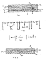
- the component according to the present invention comprises a substrate 1, on which is deposited a layered structure 2.
- the layered structure includes a back electrode 3 deposited on the substrate 1, an absorber layer 4 deposited on the back electrode 3 at least one front electrode 5 arranged on the light-receiving surface of the absorber layer 4.
- the component according to the present invention further includes a barrier layer 7 comprising the reaction product of a curable resin and a polymeric polyol.
- the barrier layer 7 extends over the outer surface of the layered structure 2 and ends on rims 8 of the substrate 1.
- the thickness of the barrier layer is suitably in the range of from 100 nm to 2 mm.
- the laminate consists of a cover 10 of transparent glass and an adhesive layer 11, by which the laminate is adhered to the barrier layer 7.
- the adhesive layer 11 is suitably a layer consisting of polyvinyl butyral having a thickness of 0.5 mm.
- the laminate is applied at a temperature of 150 °C.
- barrier layer is formed from a liquid resin composition containing a curable resin and a polymeric polyol.
- the barrier layer according to the present invention is not only moisture proof, but also it adheres so well to the substrate that diffusion of moisture along the interfaces at the rims 8 between the substrate 1 and the barrier layer 4 is prevented. Applicant had found that diffusion of moisture through the barrier layer itself was insignificant as compared to diffusion of moisture along the interfaces between the barrier layer and the substrate.
- the barrier layer according to the present invention comprises the reaction product of a curable resin and a polymeric polyol.
- the barrier layer is obtained by applying a liquid resin composition containing the curable resin and the polymer polyol on the surfaces of the component to be covered, and then allowing the polymer polyol to react with the resin.
- liquid resin composition can be done by spraying, brushing, dipping, and a spin on method, screen printing and so on.
- liquid resin composition can further be diluted with a solvent, for example for spraying or brush application, with ethoxypropyl acetate.
- the reaction between the polymeric polyol and the curable resin is allowed to proceed.
- the polymeric polyol is a higher molecular polyol, in particular with a molar mass of about 1 000 or higher.
- Examples of the polymeric polyol are polyvinyl alcohol, a polyester- and/or a polyether polyol.
- the polymer polyol employed in the present invention is polyvinyl butyral (PVB) of which the structural formula is shown in Figure 2 , which has free hydroxyl groups.
- PVB polyvinyl butyral
- n, o different physical and chemical properties are achieved.
- the molar mass or the degree of polymerisation, respectively, exhibits great importance for the thermal and mechanical properties and for the viscosity in solution.
- the polymeric polyol can as well be a mixture of the above-mentioned examples of polymeric polyols.
- the second component is a curable resin in the form of an epoxy resin.
- the second component can as well be a mixture of an epoxy resin and an isocyanate.
- the reaction between the polymer polyol and the curable resin is called hardening, setting or cross-linking. If a solvent is present, the reaction is started after flashing off the solvent.
- the reaction is carried out by ultra violet (UV) radiation treatment, for example with a commercially available mercury discharge lamp.
- the curable resin is an epoxy resin.
- the epoxy resin incorporated in the barrier layer can be an aliphatic, cycloaliphatic or aromatic epoxide, with aliphatic and cycloaliphatic, i.e. ring epoxidised, epoxides being preferred.
- the epoxy resin consists of ⁇ 70% by weight of an aliphatic and/or cycloaliphatic epoxide.
- the underlying hardening chemistry is the cationic polymerisation of epoxy resins and the copolyaddition with suitable polyhydroxyl compounds.
- PVB is a hydroxyl compound of that kind and therefore is chemically incorporated or participates in the cross-link formation of the resulting high quality moulding material.
- the resulting moulding material is duroplastic, shows a good adhesion and demonstrates good tensile strength and elasticity. Furthermore it has a good light transmitting capacity, which makes it especially suitable for the use in solar cells and light emitting components.
- the PVB containing curable resin is exposed to UV light by means of a lamp or of a laser at a wavelength that preferably corresponds to the absorption of the photoinitiator contained in the curable resin.
- the exposition is done with a mercury discharge lamp with a power density of 100 mW/cm 2 within the UV A range, at an radiation period of 20 seconds.
- a suitable liquid resin composition for the barrier according to the present invention contains epoxy compounds, particularly diepoxides (30 to 95% by weight of the composition), polyvinyl butyral, suitably 1 to 15% by weight of the composition, and photoinitiators.
- epoxy compounds particularly diepoxides (30 to 95% by weight of the composition)
- polyvinyl butyral suitably 1 to 15% by weight of the composition
- photoinitiators optionally also lacquer additives like antifoaming agents, levelling agents and/or adhesion promoting agents can be contained.
- lacquer additives like antifoaming agents, levelling agents and/or adhesion promoting agents can be contained.
- they can additionally contain solvents, which are flashed off prior to an UV hardening.
- PVB is further cross-linked with other reaction partners.
- reactants like epoxy resins, phenol resins and melamine resins are used.
- phenol resins and melamine resins are used.
- polyisocyanates and dialdehydes can be used as co-reactants.
- a thermal hardening also can take the place of UV hardening here.
- a thermal treatment preferably up to a temperature of 120 °C, can follow the UV hardening.
- the lower temperature limit lies at 10 to 20 °C below the glass-transition temperature of the hardened curable resin.
- the resin is UV-curable, i.e. it sets under the influence of UV light.
- UV curable epoxy resins are particularly suitable.
- the amount of polymeric polyol is suitably more than 1% by weight of the curable resin, in particular more than 5% by weight.
- the amount of polymeric polyol proportion is in the range of from 1% by weight to 15% by weight of the curable resin, but can be up to 30% by weight of the curable resin.
- the barrier layer may be applied in known procedures as an impermeable layer, i. e. being free from pores, optically transparent and edge covering. Depending on the impermeability or freeness from pores such a layer is manufactured with a barrier layer having a thickness of 1 micrometre can already be sufficient to ensure a sufficient protection against moisture. Of course, a thicker barrier layer is possible. For application processes where barrier layers are obtained which are not quite free of pores or not completely homogenous or do not cover the rims well, preferably a larger thickness of the barrier layer is selected. When high topographic steps are present on the layered structure, a layer thickness of up to approximately 2 mm is selected for a good edge covering of the barrier layer.
- the barrier layer is formed as a barrier layer for protection against moisture and is located at least at one outer surface of the component, which outer surface is the outer surface of the layered structure and at least part of the surface of the substrate that is not covered by the layered structure.
- the barrier layer according to the present invention adapts to the function of the covered layered structure and, for example, is optically transparent or electrically insulating, it shows no negative influence to the layered structure. Neither does it affect the operation of an optical or electrical component that is incorporated in the layered structure nor does it impair the properties thereof.
- the barrier layer demonstrates good adhesion on most materials that are used as an electrical or optical function layer or the substrate. Possibly an additional adhesion providing layer may be necessary.
- the barrier layer according to the invention is especially suitable for applying a laminate covering it, as it demonstrates good adhesion on or under conventional hot melt adhesive layers, used therefore. This results from the close connection between polymeric polyol and laminate.
- the good adhesion of the hot melt adhesive film, and hence of the entire laminate structure, results in an additional improved impermeability, which prevents diffusion of moisture along the interfaces between layered structure and laminate or between barrier layer and laminate, respectively.
- the barrier layer encloses the layered structure that is sensitive to moisture from above and from the side and ends at the lower edge on the substrate that for example consists of glass.
- the barrier layer according to the present invention can also cover a metal layer or a passivation layer.
- the passivation layer can also be an inorganic barrier layer. Suitable materials for a passivation layer are silicon oxide, titanium nitride and molybdenum nitride. The latter two are particularly hard and scratch resistant as well.
- the barrier layer of the present invention demonstrates good adhesion to all the layers and thus form moisture-impermeable and chemically stable interfaces to these layers.
- the layered structure is an electrical component having at least two electrodes wherein one electrode is formed by an electrode layer located directly on the substrate.
- This electrode is called a back electrode, and the back electrode can be structured, to obtain an electrode structure that is particularly suitable for integrated series connected thin film solar modules.
- the electrical connections for the at least two electrodes can be formed from this back electrode layer and led out of the component region laterally.
- Such an arrangement has the advantage that it can be formed particularly flat without additional structure steps, as opposed to a conventional arrangement with, for example, electrical connections soldered on. This facilitates an edge covering envelopment with the barrier layer according to the invention.
- Another advantageous embodiment of the invention relates to the already mentioned CIS thin film solar modules.
- a defined alkali content in the CIS absorber layer is necessary for a maximum efficiency of the solar cell. Since with the use of a glass substrate a defined alkali content of the CIS absorber layer can only be achieved with an alkali barrier layer directly above the glass substrate or above the back electrode layer, a barrier layer according to the invention, formed as a passivating layer above the back electrode can be used for such a barrier layer in a favourable manner.
- a barrier layer made of titanium or molybdenum nitride can serve as a passivation layer for the electrical connections leading to the outside, or as a barrier layer for the entire lower electrode, respectively. It exhibits particularly good adhesion to an additional barrier layer above the solar cell and forms a particularly good and impermeable interface to the barrier layer therewith.
- FIG. 4 showing schematically a cross-section of the test component.
- a boron doped zinc oxide layer 21 having a thickness of 1.5 micrometre is applied by means of chemical vapour deposition.
- strips of zinc oxide of 10 mm width are removed from the substrate 20, so as to make four uncovered rims of which rims 23 and 24 are shown in Figure 4 .
- two metallic contact strips are joined to the zinc oxide layer on opposite sides thereof, so that the sheet resistance of the zinc oxide layer can be determined reliably.
- a barrier layer 26 was applied, as will be discussed below. Thereafter a glass cover 28 was adhered to the barrier layer by means of an adhesive layer of polyvinyl butyral 29.
- the adhesive layer 29 having a thickness of 0.5 mm, was allowed to set under 145 °C for 30 minutes under pressure.
- the pressure was applied on the glass cover 28 by means of a membrane (not shown) separating a vacuum chamber (with the component in it) and a pressurized chamber, and the pressure difference over the membrane was 450 millibar.
- the barrier layer according to the present invention was prepared as follows. First a liquid resin composition was prepared.
- the liquid resin composition consisted of: 35 g polyvinyl butyral, 357 g cycloaliphatic epoxy resin, 236 g OH-134, consisting of bisphenol A and cycloaliphatic epoxy resin Araldit CY 179 in the proportion of 1:3, 157 g epoxidized soy bean oil, 197 g trifunctional polyester polyol, 9.8 g triarylsulphonium hexafluoroantimonate, 3.9 g (3-glycidoxypropyl)-trimethoxysilane, 3.4 g dimethylpolysiloxane derivative.
- the liquid resin composition was brushed over the component so as to cover the zinc oxide layer and the rims 23 and 24 around the zinc oxide layer. And under UV conditions, the resin composition was allowed to harden.
- barrier layer consisting of a conventional resin.
- the barrier layer was made using a liquid resin composition consisting of a two-component lacquer 1640 (from Rhenatech Elektroisoliersysteme) - comparative example A.
- the barrier layer was made using a liquid UV-curable acrylate resin composition Multi-Cure 984 (Trade name) LVUF (from Dymax Europe GmbH) - comparative example B.
- the Table shows the improvement obtained with the barrier layer according to the present invention.
- the climate and corrosion stable encapsulation of any layered structure and in particular thin film arrangements with a large surface, which comprise climate and corrosion sensitive layers can successfully be done.
- the invention is particularly suitable for such thin film arrangements that are exposed to hot and/or humid environments, such as solar cells. Of course this is also valid for layered structures that are usually not exposed to such corrosion promoting environmental conditions.
Landscapes
- Chemical & Material Sciences (AREA)
- Health & Medical Sciences (AREA)
- Chemical Kinetics & Catalysis (AREA)
- Medicinal Chemistry (AREA)
- Polymers & Plastics (AREA)
- Organic Chemistry (AREA)
- Electromagnetism (AREA)
- Condensed Matter Physics & Semiconductors (AREA)
- Physics & Mathematics (AREA)
- General Physics & Mathematics (AREA)
- Engineering & Computer Science (AREA)
- Computer Hardware Design (AREA)
- Microelectronics & Electronic Packaging (AREA)
- Power Engineering (AREA)
- Photovoltaic Devices (AREA)
- Laminated Bodies (AREA)
- Epoxy Resins (AREA)
- Sealing Material Composition (AREA)
Claims (15)
- Cellule solaire comprenant un substrat, une structure feuilletée disposée sur le substrat, et une couche barrière disposée sur la structure feuilletée, la structure feuilletée comprenant un film optiquement actif ou un film électriquement actif et la couche barrière comprenant le produit de réaction d'un polyol polymère et d'une résine durcissable, caractérisée par le fait que la résine durcissable est une résine époxy et que le polyol polymère est le butyral polyvinylique.
- Composant selon la revendication 1, caractérisé par le fait que la couche barrière est située au moins à une surface externe du composant.
- Composant selon l'une des revendications 1 ou 2, caractérisé par le fait que la couche barrière est imperméable et à recouvrement de la bordure.
- Composant selon l'une quelconque des revendications 1 à 3, caractérisé par le fait que le composant comprend en outre une structure feuilletée avec une couverture et une couche adhésive intermédiaire qui est disposée sur la couche barrière.
- Composant selon la revendication 4, caractérisé par le fait que la couverture comprend au moins une couche de matière plastique.
- Composant selon la revendication 4, caractérisé par le fait que la couverture est une plaque de verre.
- Composant selon la revendication 4, dans lequel la couche adhésive intermédiaire est une couche de butyral polyvinylique.
- Composant selon l'une quelconque des revendications 1 à 6, caractérisé par le fait que la quantité de polyol polymère est supérieure à 1 % en poids de la résine durcissable, en particulier se situant dans la plage de 1 % à 30 % en poids de la résine durcissable.
- Composant selon l'une quelconque des revendications 1 à 7, caractérisé par le fait que la résine durcissable est durcissable sous l'action d'un rayonnement UV.
- Composant selon l'une des revendications 1 ou 2, dans lequel la structure feuilletée comprend une couche d'absorbeur sensible à l'humidité, en particulier dans lequel la couche d'absorbeur sensible à l'humidité comprend un diséléniure de cuivre et d'indium.
- Composant selon l'une des revendications 1 ou 2, dans lequel la couche barrière s'étend sur la surface externe de la structure feuilletée.
- Procédé de fabrication d'une cellule solaire comprenant les étapes de :- se procurer un substrat ;- déposer une structure feuilletée comprenant une couche d'absorbeur sensible à l'humidité sur le substrat ;- appliquer une composition de résine liquide contenant un polyol polymère et une résine durcissable sur les surfaces de la structure feuilletée et amener le polyol polymère à réagir avec la résine de façon à former une couche barrière protégeant la structure feuilletée de l'humidité, le polyol polymère étant le butyral polyvinylique, et la résine durcissable étant une résine époxy.
- Procédé selon la revendication 12, dans lequel le procédé comprend en outre l'opération consistant à laminer une couverture au moyen d'une couche adhésive sur la couche barrière, en particulier dans lequel la couche adhésive est une couche de butyral polyvinylique.
- Procédé selon l'une des revendications 12 ou 13, dans lequel la réaction est effectuée par un traitement par rayonnement ultraviolet.
- Utilisation d'une composition de résine liquide contenant un polyol polymère et une résine durcissable pour former une couche barrière sur une structure feuilletée sensible à l'humidité déposée sur un substrat, par application de la composition de résine liquide sur la structure feuilletée et en amenant le polyol polymère à réagir avec la résine, permettant ainsi de protéger la structure feuilletée de l'humidité, la résine durcissable étant une résine époxy et le polyol polymère étant le butyral polyvinylique et la structure feuilletée déposée sur un substrat étant une cellule solaire.
Applications Claiming Priority (3)
| Application Number | Priority Date | Filing Date | Title |
|---|---|---|---|
| DE10204049 | 2002-02-01 | ||
| DE10204049 | 2002-02-01 | ||
| PCT/EP2003/001073 WO2003064529A1 (fr) | 2002-02-01 | 2003-01-31 | Couche barriere constituee par une resine durcissante contenant un polyol polymere |
Publications (2)
| Publication Number | Publication Date |
|---|---|
| EP1470191A1 EP1470191A1 (fr) | 2004-10-27 |
| EP1470191B1 true EP1470191B1 (fr) | 2012-11-21 |
Family
ID=27634753
Family Applications (1)
| Application Number | Title | Priority Date | Filing Date |
|---|---|---|---|
| EP03704525A Expired - Lifetime EP1470191B1 (fr) | 2002-02-01 | 2003-01-31 | Couche barriere constituee par une resine durcissante contenant un polyol polymere |
Country Status (6)
| Country | Link |
|---|---|
| US (1) | US7255926B2 (fr) |
| EP (1) | EP1470191B1 (fr) |
| JP (1) | JP4927317B2 (fr) |
| CN (1) | CN100336210C (fr) |
| ES (1) | ES2396118T3 (fr) |
| WO (1) | WO2003064529A1 (fr) |
Families Citing this family (15)
| Publication number | Priority date | Publication date | Assignee | Title |
|---|---|---|---|---|
| JP2007287894A (ja) * | 2006-04-17 | 2007-11-01 | Showa Shell Sekiyu Kk | パターン表示機能付cis系薄膜太陽電池モジュール及びその製造方法 |
| JP2010521822A (ja) * | 2007-03-14 | 2010-06-24 | エバーグリーン ソーラー, インコーポレイテッド | 補剛層を有する太陽電池モジュール |
| WO2008150769A2 (fr) * | 2007-05-31 | 2008-12-11 | Thinsilicon Corporation | Dispositif photovoltaïque et procédé de fabrication de dispositifs photovoltaïques |
| AT506100A1 (de) * | 2007-12-13 | 2009-06-15 | Isovolta | Photovoltaisches modul mit primerschicht |
| JP2012504350A (ja) * | 2008-09-29 | 2012-02-16 | シンシリコン・コーポレーション | 一体的に統合されたソーラーモジュール |
| WO2010144480A2 (fr) * | 2009-06-10 | 2010-12-16 | Thinsilicon Corporation | Module photovoltaïque et procédé de production d'un module photovoltaïque comprenant plusieurs empilements de couches semi-conductrices |
| US20110048505A1 (en) * | 2009-08-27 | 2011-03-03 | Gabriela Bunea | Module Level Solution to Solar Cell Polarization Using an Encapsulant with Opened UV Transmission Curve |
| JP5310436B2 (ja) * | 2009-09-18 | 2013-10-09 | デクセリアルズ株式会社 | 太陽電池モジュール及びその製造方法 |
| CN102742028B (zh) * | 2010-02-15 | 2016-02-03 | 迪睿合电子材料有限公司 | 薄膜型太阳电池模块的制造方法 |
| TWI432320B (zh) | 2010-08-09 | 2014-04-01 | Ind Tech Res Inst | 封裝膜、封裝結構與其形成方法 |
| CN104795465A (zh) * | 2015-04-10 | 2015-07-22 | 杭州福斯特光伏材料股份有限公司 | 一种太阳能电池组件的封装方法 |
| DE102015112233B4 (de) | 2015-07-27 | 2021-12-09 | Granula Polymer Gmbh | Verfahren zur Herstellung von Folien und Membranen umfassend hyperverzweigte Copolymere auf Basis von Oxetan, Folien und Membranen, die nach diesem Verfahren erhalten werden, sowie deren Verwendung |
| EP3708359A4 (fr) * | 2017-11-07 | 2021-08-25 | Toyo Seikan Group Holdings, Ltd. | Film stratifié faisant barrière à l'humidité |
| CN112789164B (zh) * | 2018-10-04 | 2023-12-01 | 中央硝子株式会社 | 多功能调光膜和包括此类膜的构造体 |
| RU2742680C1 (ru) * | 2020-09-18 | 2021-02-09 | Федеральное государственное бюджетное научное учреждение "Федеральный научный агроинженерный центр ВИМ" (ФГБНУ ФНАЦ ВИМ) | Оконная створка со встроенным фотоэлектрическим модулем с увеличенным сроком службы и способ её изготовления |
Family Cites Families (26)
| Publication number | Priority date | Publication date | Assignee | Title |
|---|---|---|---|---|
| US628326A (en) * | 1898-01-26 | 1899-07-04 | P H Keefe | Belt-fastener. |
| AU517415B2 (en) * | 1976-07-09 | 1981-07-30 | General Electric Company | Curable polymer composition |
| US4193799A (en) * | 1976-07-09 | 1980-03-18 | General Electric Company | Method of making printing plates and printed circuit |
| DE3013037C2 (de) * | 1980-04-03 | 1985-09-12 | Licentia Patent-Verwaltungs-Gmbh, 6000 Frankfurt | Terrestrischer Solargenerator |
| US4719255A (en) * | 1984-08-23 | 1988-01-12 | Kabushiki Kaisha Toshiba | Epoxy resin composition for encapsulation of semi-conductor device |
| JPS6153320A (ja) * | 1984-08-23 | 1986-03-17 | Toshiba Corp | 半導体装置封止用エポキシ樹脂組成物 |
| CA1312040C (fr) * | 1985-12-19 | 1992-12-29 | Joseph Victor Koleske | Revetements conformables durcis par des radiations actiniques |
| JPH0692467B2 (ja) | 1986-10-06 | 1994-11-16 | 信越化学工業株式会社 | 可逆性含水ゲルとその製造方法 |
| DD263647A1 (de) * | 1987-08-19 | 1989-01-04 | Zentr Wissenschaft & Tech Veb | Verfahren zur umhuellung von elektrischen baugruppen mit weichen harzen |
| KR100189642B1 (ko) * | 1991-02-18 | 1999-06-01 | 디어터 크리스트 | 전자 부품 및 조립체를 피복시키거나 접착시키는 방법 |
| ES2106851T3 (es) | 1991-06-19 | 1997-11-16 | Ciba Geigy Ag | Nuevo sistema de resinas con baja temperatura de moldeo. |
| EP0540467A1 (fr) * | 1991-10-29 | 1993-05-05 | Ciba-Geigy Ag | Compositions de résines époxydes stabilisées |
| US5631315A (en) * | 1993-07-01 | 1997-05-20 | Monsanto Company | Plasticized polyvinyl butyral sheet containing epoxy resin |
| DE4442824C1 (de) | 1994-12-01 | 1996-01-25 | Siemens Ag | Solarzelle mit Chalkopyrit-Absorberschicht |
| US5602457A (en) * | 1995-01-03 | 1997-02-11 | Exide Corporation | Photovoltaic solar cell laminated in vehicle windshield |
| DE19514908C1 (de) | 1995-04-22 | 1996-04-18 | Ver Glaswerke Gmbh | Verfahren zur Herstellung eines Solarmoduls |
| WO1997002728A1 (fr) | 1995-07-04 | 1997-01-23 | Mitsui Mining & Smelting Co., Ltd. | Feuille de cuivre revetue de resine pour panneau de cablage multicouches imprime et panneau de cablage multicouches imprime le contenant |
| DE19534664A1 (de) * | 1995-09-19 | 1997-03-20 | Thera Ges Fuer Patente | Lichtinitiiert kationisch härtende, dauerflexible Epoxidharzmasse und ihre Verwendung |
| DE19707280A1 (de) | 1997-02-24 | 1998-08-27 | Siemens Ag | Klima- und korrosionsstabiler Schichtaufbau |
| JP3873372B2 (ja) * | 1997-05-26 | 2007-01-24 | 住友化学株式会社 | ポジ型フォトレジスト組成物 |
| JP3740251B2 (ja) | 1997-06-09 | 2006-02-01 | キヤノン株式会社 | 太陽電池モジュールの製造方法 |
| JPH11135820A (ja) * | 1997-08-27 | 1999-05-21 | Canon Inc | 太陽電池モジュール及び太陽電池モジュール用補強部材 |
| JP2000150936A (ja) * | 1998-11-17 | 2000-05-30 | Canon Inc | 半導体装置及び太陽光発電装置 |
| EP1039551B2 (fr) | 1999-03-23 | 2010-09-15 | Kaneka Corporation | Module photovoltaique |
| DE19943149A1 (de) | 1999-09-09 | 2001-04-05 | Siemens Ag | Verfahren zur Verkapselung von Bauelementen |
| DE10065530A1 (de) * | 2000-12-28 | 2002-07-04 | Bosch Gmbh Robert | Einrichtung zur Stromerzeugung und zum Abschatten bei Kraftfahrzeugen |
-
2003
- 2003-01-31 WO PCT/EP2003/001073 patent/WO2003064529A1/fr active Application Filing
- 2003-01-31 CN CNB038030160A patent/CN100336210C/zh not_active Expired - Fee Related
- 2003-01-31 US US10/503,165 patent/US7255926B2/en not_active Expired - Fee Related
- 2003-01-31 EP EP03704525A patent/EP1470191B1/fr not_active Expired - Lifetime
- 2003-01-31 JP JP2003564133A patent/JP4927317B2/ja not_active Expired - Fee Related
- 2003-01-31 ES ES03704525T patent/ES2396118T3/es not_active Expired - Lifetime
Also Published As
| Publication number | Publication date |
|---|---|
| US20050072459A1 (en) | 2005-04-07 |
| ES2396118T3 (es) | 2013-02-19 |
| WO2003064529A1 (fr) | 2003-08-07 |
| CN100336210C (zh) | 2007-09-05 |
| US7255926B2 (en) | 2007-08-14 |
| JP4927317B2 (ja) | 2012-05-09 |
| JP2005515920A (ja) | 2005-06-02 |
| EP1470191A1 (fr) | 2004-10-27 |
| CN1625582A (zh) | 2005-06-08 |
Similar Documents
| Publication | Publication Date | Title |
|---|---|---|
| EP1470191B1 (fr) | Couche barriere constituee par une resine durcissante contenant un polyol polymere | |
| US6501014B1 (en) | Coated article and solar battery module | |
| EP0629004B1 (fr) | Matériau de revêtement pour module de cellules solaires | |
| JP3387741B2 (ja) | 半導体素子用保護材、該保護材を有する半導体素子、該素子を有する半導体装置 | |
| CN1145220C (zh) | 太阳能电池组件及其应用 | |
| US6175075B1 (en) | Solar cell module excelling in reliability | |
| ES2197971T3 (es) | Modulo de celula solar con cubierta superficial especifica con buenas caracteristicas de resistencia a humedad y transparencia. | |
| EP1783159B1 (fr) | Film de résine | |
| KR101286282B1 (ko) | 프레임리스 태양 전지 패널 및 그 제조 방법 | |
| US4852979A (en) | Encapsulated electrochromic mirror and method of making same | |
| KR101074505B1 (ko) | 광전지 모듈 | |
| CA2690584A1 (fr) | Module photovoltaique comprenant un film polymere et procede de fabrication d'un tel module | |
| KR101074506B1 (ko) | 광전지 모듈 | |
| EP0577985B1 (fr) | Module solaire en semi-conducteur amorphe ayant une passivation améliorée | |
| JP2010003861A (ja) | 太陽電池モジュールの製造方法 | |
| JP2009277891A (ja) | 薄膜太陽電池モジュール | |
| JP3978911B2 (ja) | 太陽電池用カバー材、封止膜及び太陽電池 | |
| KR101064584B1 (ko) | 광전지용 시트 | |
| KR101733054B1 (ko) | 태양전지 모듈 | |
| JP2010003860A (ja) | 太陽電池モジュール及びその製造方法 | |
| JPH0955528A (ja) | 太陽電池モジュールの端子取り出し部構造 | |
| JPH11112007A (ja) | 太陽電池モジュール及びその製造方法 | |
| JPH08231675A (ja) | 樹脂組成物およびそれを有する電子ディバイス | |
| JPS61274373A (ja) | 太陽電池用裏面保護シ−ト | |
| JPH06151935A (ja) | 太陽電池モジュールの製造方法 |
Legal Events
| Date | Code | Title | Description |
|---|---|---|---|
| PUAI | Public reference made under article 153(3) epc to a published international application that has entered the european phase |
Free format text: ORIGINAL CODE: 0009012 |
|
| 17P | Request for examination filed |
Effective date: 20040722 |
|
| AK | Designated contracting states |
Kind code of ref document: A1 Designated state(s): AT BE BG CH CY CZ DE DK EE ES FI FR GB GR HU IE IT LI LU MC NL PT SE SI SK TR |
|
| AX | Request for extension of the european patent |
Extension state: AL LT LV MK RO |
|
| RAP1 | Party data changed (applicant data changed or rights of an application transferred) |
Owner name: SHELL ERNEUERBARE ENERGIEN GMBH |
|
| 17Q | First examination report despatched |
Effective date: 20070921 |
|
| RAP1 | Party data changed (applicant data changed or rights of an application transferred) |
Owner name: SAINT-GOBAIN GLASS FRANCE S.A. |
|
| GRAP | Despatch of communication of intention to grant a patent |
Free format text: ORIGINAL CODE: EPIDOSNIGR1 |
|
| GRAJ | Information related to disapproval of communication of intention to grant by the applicant or resumption of examination proceedings by the epo deleted |
Free format text: ORIGINAL CODE: EPIDOSDIGR1 |
|
| GRAS | Grant fee paid |
Free format text: ORIGINAL CODE: EPIDOSNIGR3 |
|
| GRAP | Despatch of communication of intention to grant a patent |
Free format text: ORIGINAL CODE: EPIDOSNIGR1 |
|
| GRAA | (expected) grant |
Free format text: ORIGINAL CODE: 0009210 |
|
| AK | Designated contracting states |
Kind code of ref document: B1 Designated state(s): AT BE BG CH CY CZ DE DK EE ES FI FR GB GR HU IE IT LI LU MC NL PT SE SI SK TR |
|
| REG | Reference to a national code |
Ref country code: GB Ref legal event code: FG4D |
|
| REG | Reference to a national code |
Ref country code: CH Ref legal event code: EP |
|
| REG | Reference to a national code |
Ref country code: AT Ref legal event code: REF Ref document number: 585083 Country of ref document: AT Kind code of ref document: T Effective date: 20121215 |
|
| REG | Reference to a national code |
Ref country code: IE Ref legal event code: FG4D |
|
| REG | Reference to a national code |
Ref country code: DE Ref legal event code: R096 Ref document number: 60342635 Country of ref document: DE Effective date: 20130117 |
|
| REG | Reference to a national code |
Ref country code: ES Ref legal event code: FG2A Ref document number: 2396118 Country of ref document: ES Kind code of ref document: T3 Effective date: 20130219 |
|
| REG | Reference to a national code |
Ref country code: NL Ref legal event code: VDEP Effective date: 20121121 |
|
| PG25 | Lapsed in a contracting state [announced via postgrant information from national office to epo] |
Ref country code: SE Free format text: LAPSE BECAUSE OF FAILURE TO SUBMIT A TRANSLATION OF THE DESCRIPTION OR TO PAY THE FEE WITHIN THE PRESCRIBED TIME-LIMIT Effective date: 20121121 Ref country code: FI Free format text: LAPSE BECAUSE OF FAILURE TO SUBMIT A TRANSLATION OF THE DESCRIPTION OR TO PAY THE FEE WITHIN THE PRESCRIBED TIME-LIMIT Effective date: 20121121 |
|
| PG25 | Lapsed in a contracting state [announced via postgrant information from national office to epo] |
Ref country code: PT Free format text: LAPSE BECAUSE OF FAILURE TO SUBMIT A TRANSLATION OF THE DESCRIPTION OR TO PAY THE FEE WITHIN THE PRESCRIBED TIME-LIMIT Effective date: 20130321 Ref country code: BE Free format text: LAPSE BECAUSE OF FAILURE TO SUBMIT A TRANSLATION OF THE DESCRIPTION OR TO PAY THE FEE WITHIN THE PRESCRIBED TIME-LIMIT Effective date: 20121121 Ref country code: GR Free format text: LAPSE BECAUSE OF FAILURE TO SUBMIT A TRANSLATION OF THE DESCRIPTION OR TO PAY THE FEE WITHIN THE PRESCRIBED TIME-LIMIT Effective date: 20130222 Ref country code: SI Free format text: LAPSE BECAUSE OF FAILURE TO SUBMIT A TRANSLATION OF THE DESCRIPTION OR TO PAY THE FEE WITHIN THE PRESCRIBED TIME-LIMIT Effective date: 20121121 |
|
| PG25 | Lapsed in a contracting state [announced via postgrant information from national office to epo] |
Ref country code: SK Free format text: LAPSE BECAUSE OF FAILURE TO SUBMIT A TRANSLATION OF THE DESCRIPTION OR TO PAY THE FEE WITHIN THE PRESCRIBED TIME-LIMIT Effective date: 20121121 Ref country code: BG Free format text: LAPSE BECAUSE OF FAILURE TO SUBMIT A TRANSLATION OF THE DESCRIPTION OR TO PAY THE FEE WITHIN THE PRESCRIBED TIME-LIMIT Effective date: 20130221 Ref country code: CZ Free format text: LAPSE BECAUSE OF FAILURE TO SUBMIT A TRANSLATION OF THE DESCRIPTION OR TO PAY THE FEE WITHIN THE PRESCRIBED TIME-LIMIT Effective date: 20121121 Ref country code: DK Free format text: LAPSE BECAUSE OF FAILURE TO SUBMIT A TRANSLATION OF THE DESCRIPTION OR TO PAY THE FEE WITHIN THE PRESCRIBED TIME-LIMIT Effective date: 20121121 Ref country code: EE Free format text: LAPSE BECAUSE OF FAILURE TO SUBMIT A TRANSLATION OF THE DESCRIPTION OR TO PAY THE FEE WITHIN THE PRESCRIBED TIME-LIMIT Effective date: 20121121 |
|
| PG25 | Lapsed in a contracting state [announced via postgrant information from national office to epo] |
Ref country code: MC Free format text: LAPSE BECAUSE OF NON-PAYMENT OF DUE FEES Effective date: 20130131 Ref country code: NL Free format text: LAPSE BECAUSE OF FAILURE TO SUBMIT A TRANSLATION OF THE DESCRIPTION OR TO PAY THE FEE WITHIN THE PRESCRIBED TIME-LIMIT Effective date: 20121121 |
|
| PLBE | No opposition filed within time limit |
Free format text: ORIGINAL CODE: 0009261 |
|
| STAA | Information on the status of an ep patent application or granted ep patent |
Free format text: STATUS: NO OPPOSITION FILED WITHIN TIME LIMIT |
|
| REG | Reference to a national code |
Ref country code: IE Ref legal event code: MM4A |
|
| 26N | No opposition filed |
Effective date: 20130822 |
|
| REG | Reference to a national code |
Ref country code: DE Ref legal event code: R097 Ref document number: 60342635 Country of ref document: DE Effective date: 20130822 |
|
| PG25 | Lapsed in a contracting state [announced via postgrant information from national office to epo] |
Ref country code: IE Free format text: LAPSE BECAUSE OF NON-PAYMENT OF DUE FEES Effective date: 20130131 |
|
| PGFP | Annual fee paid to national office [announced via postgrant information from national office to epo] |
Ref country code: CH Payment date: 20150124 Year of fee payment: 13 |
|
| PGFP | Annual fee paid to national office [announced via postgrant information from national office to epo] |
Ref country code: AT Payment date: 20150127 Year of fee payment: 13 |
|
| PG25 | Lapsed in a contracting state [announced via postgrant information from national office to epo] |
Ref country code: CY Free format text: LAPSE BECAUSE OF FAILURE TO SUBMIT A TRANSLATION OF THE DESCRIPTION OR TO PAY THE FEE WITHIN THE PRESCRIBED TIME-LIMIT Effective date: 20121121 Ref country code: TR Free format text: LAPSE BECAUSE OF FAILURE TO SUBMIT A TRANSLATION OF THE DESCRIPTION OR TO PAY THE FEE WITHIN THE PRESCRIBED TIME-LIMIT Effective date: 20121121 |
|
| PG25 | Lapsed in a contracting state [announced via postgrant information from national office to epo] |
Ref country code: HU Free format text: LAPSE BECAUSE OF FAILURE TO SUBMIT A TRANSLATION OF THE DESCRIPTION OR TO PAY THE FEE WITHIN THE PRESCRIBED TIME-LIMIT; INVALID AB INITIO Effective date: 20030131 Ref country code: LU Free format text: LAPSE BECAUSE OF NON-PAYMENT OF DUE FEES Effective date: 20130131 |
|
| REG | Reference to a national code |
Ref country code: FR Ref legal event code: PLFP Year of fee payment: 14 |
|
| PGFP | Annual fee paid to national office [announced via postgrant information from national office to epo] |
Ref country code: ES Payment date: 20160226 Year of fee payment: 14 Ref country code: IT Payment date: 20160201 Year of fee payment: 14 Ref country code: DE Payment date: 20160331 Year of fee payment: 14 |
|
| PGFP | Annual fee paid to national office [announced via postgrant information from national office to epo] |
Ref country code: FR Payment date: 20160201 Year of fee payment: 14 Ref country code: GB Payment date: 20160201 Year of fee payment: 14 |
|
| REG | Reference to a national code |
Ref country code: CH Ref legal event code: PL |
|
| REG | Reference to a national code |
Ref country code: AT Ref legal event code: MM01 Ref document number: 585083 Country of ref document: AT Kind code of ref document: T Effective date: 20160131 |
|
| PG25 | Lapsed in a contracting state [announced via postgrant information from national office to epo] |
Ref country code: LI Free format text: LAPSE BECAUSE OF NON-PAYMENT OF DUE FEES Effective date: 20160131 Ref country code: CH Free format text: LAPSE BECAUSE OF NON-PAYMENT OF DUE FEES Effective date: 20160131 |
|
| PG25 | Lapsed in a contracting state [announced via postgrant information from national office to epo] |
Ref country code: AT Free format text: LAPSE BECAUSE OF NON-PAYMENT OF DUE FEES Effective date: 20160131 |
|
| REG | Reference to a national code |
Ref country code: DE Ref legal event code: R119 Ref document number: 60342635 Country of ref document: DE |
|
| GBPC | Gb: european patent ceased through non-payment of renewal fee |
Effective date: 20170131 |
|
| REG | Reference to a national code |
Ref country code: FR Ref legal event code: ST Effective date: 20170929 |
|
| PG25 | Lapsed in a contracting state [announced via postgrant information from national office to epo] |
Ref country code: FR Free format text: LAPSE BECAUSE OF NON-PAYMENT OF DUE FEES Effective date: 20170131 |
|
| PG25 | Lapsed in a contracting state [announced via postgrant information from national office to epo] |
Ref country code: GB Free format text: LAPSE BECAUSE OF NON-PAYMENT OF DUE FEES Effective date: 20170131 Ref country code: DE Free format text: LAPSE BECAUSE OF NON-PAYMENT OF DUE FEES Effective date: 20170801 |
|
| PG25 | Lapsed in a contracting state [announced via postgrant information from national office to epo] |
Ref country code: IT Free format text: LAPSE BECAUSE OF NON-PAYMENT OF DUE FEES Effective date: 20170131 |
|
| PG25 | Lapsed in a contracting state [announced via postgrant information from national office to epo] |
Ref country code: ES Free format text: LAPSE BECAUSE OF NON-PAYMENT OF DUE FEES Effective date: 20170131 |
|
| REG | Reference to a national code |
Ref country code: ES Ref legal event code: FD2A Effective date: 20181113 |
|
| PG25 | Lapsed in a contracting state [announced via postgrant information from national office to epo] |
Ref country code: ES Free format text: LAPSE BECAUSE OF NON-PAYMENT OF DUE FEES Effective date: 20170201 |