EP1470060B1 - Valve de distribution d'aerosol a fonctionnement intermittent - Google Patents
Valve de distribution d'aerosol a fonctionnement intermittent Download PDFInfo
- Publication number
- EP1470060B1 EP1470060B1 EP03732057A EP03732057A EP1470060B1 EP 1470060 B1 EP1470060 B1 EP 1470060B1 EP 03732057 A EP03732057 A EP 03732057A EP 03732057 A EP03732057 A EP 03732057A EP 1470060 B1 EP1470060 B1 EP 1470060B1
- Authority
- EP
- European Patent Office
- Prior art keywords
- valve assembly
- diaphragm
- valve
- active chemical
- accumulation chamber
- Prior art date
- Legal status (The legal status is an assumption and is not a legal conclusion. Google has not performed a legal analysis and makes no representation as to the accuracy of the status listed.)
- Expired - Lifetime
Links
Images
Classifications
-
- B—PERFORMING OPERATIONS; TRANSPORTING
- B65—CONVEYING; PACKING; STORING; HANDLING THIN OR FILAMENTARY MATERIAL
- B65D—CONTAINERS FOR STORAGE OR TRANSPORT OF ARTICLES OR MATERIALS, e.g. BAGS, BARRELS, BOTTLES, BOXES, CANS, CARTONS, CRATES, DRUMS, JARS, TANKS, HOPPERS, FORWARDING CONTAINERS; ACCESSORIES, CLOSURES, OR FITTINGS THEREFOR; PACKAGING ELEMENTS; PACKAGES
- B65D83/00—Containers or packages with special means for dispensing contents
- B65D83/14—Containers or packages with special means for dispensing contents for delivery of liquid or semi-liquid contents by internal gaseous pressure, i.e. aerosol containers comprising propellant for a product delivered by a propellant
- B65D83/16—Containers or packages with special means for dispensing contents for delivery of liquid or semi-liquid contents by internal gaseous pressure, i.e. aerosol containers comprising propellant for a product delivered by a propellant characterised by the actuating means
- B65D83/26—Containers or packages with special means for dispensing contents for delivery of liquid or semi-liquid contents by internal gaseous pressure, i.e. aerosol containers comprising propellant for a product delivered by a propellant characterised by the actuating means operating automatically, e.g. periodically
- B65D83/265—Containers or packages with special means for dispensing contents for delivery of liquid or semi-liquid contents by internal gaseous pressure, i.e. aerosol containers comprising propellant for a product delivered by a propellant characterised by the actuating means operating automatically, e.g. periodically by fall or rise in pressure or temperature
Definitions
- the present invention relates to aerosol dispensing devices, and in particular to valve assemblies that provide automatic dispensing of aerosol content at predetermined time intervals, without requiring the use of electrical power.
- Aerosol cans dispense a variety of ingredients.
- an active is mixed with a propellant which inside the can is at least partially in a gas state, but may also be at least partially dissolved into a liquid containing active.
- Typical propellants are a propane/butane mix or carbon dioxide.
- the mixture is stored under pressure in the aerosol can.
- the active mixture is then sprayed by pushing down/sideways on an activator button at the top of the can that controls a release valve.
- active chemical is used to mean that portion of the content of the container (regardless of whether in emulsion state, single phase, or multiple phase), which is in liquid phase in the container (regardless of phase outside the container) and has a desired active such as an insect control agent (repellent or insecticide or growth regulator), fragrance, sanitizer, and/or deodorizer alone and/or mixed in a solvent, and/or mixed with a portion of the propellant.
- insect control agent repelent or insecticide or growth regulator
- fragrance repellent or insecticide or growth regulator
- sanitizer sanitizer
- deodorizer alone and/or mixed in a solvent, and/or mixed with a portion of the propellant.
- Pressure on a valve control button is typically supplied by finger pressure.
- finger pressure For fragrances, deodorizers, insecticides, and certain other actives which are sprayed directly into the air, it is sometimes desirable to periodically refresh the concentration of active in the air. While this can be done manually, there are situations where this is inconvenient. For example, when an insect repellant is being sprayed to protect a room overnight (instead of using a burnable mosquito coil), the consumer will not want to wake up in the middle of the night just to manually spray more repellant.
- U.S. Pat. No. 4,077,542 relies on a biased diaphragm to control bursts of aerosol gas at periodic intervals. See also U.S. Pat. Nos. 3,477,613 and 3,658,209.
- biased diaphragm systems have suffered from reliability problems (e.g. clogging, leakage, uneven delivery). Moreover, they sometimes do not securely attach to the aerosol can.
- Document JP 56 037070 - shows a valve assembly for intermittently spraying product from an aerosol can.
- the assembly has two conduits connecting to the interior of the can. One leads to the product in the bottom of the can. The other connects to the gas space at the top of the can and leads to an accumulation chamber.
- a diaphragm releases pressure from the axially remote side of a main valve for the product.
- a main product valve opens. This results in a burst of product exiting the device from the main nozzle.
- Further filling of the accumulation chamber pulls a diaphragm central stem fully away from the axially remote end of the main valve and uncovers a dedicated discharge passage for the propellant gas leading directly to atmosphere.
- Document JP 56 070865 - shows another intermittently actuating valve for an aerosol can in which the can has separate channels for propellant gas and product.
- the propellant gas is fed via a control regulating valve through a side feed conduit to the far side of a diaphragm where it pressurizes the accumulation chamber.
- the diaphragm presses a button, which in turn operates a downstream main valve for the product. Actuation of the main valve stem also opens an ancillary valve allowing discharge of propellant gas from the accumulation chamber to atmosphere.
- JP 57 174173 Yet another prior art arrangement is shown in JP 57 174173.
- a can has a valve with two stages of operation. A small movement allows only propellant gas to exit via a gas outlet. Further pressure allows product to exit via a product outlet.
- the valve assembly is affixed to the can, the valve in the top of the can is actuated to the extent to allow the propellant gas to enter a conduit where it leads to the end of the assembly remote from the can. It passes via a control valve to an accumulation chamber. When it fills the accumulation chamber to a threshold pressure a diaphragm flips and presses the top of a valve body which presses further on the aerosol can valve allowing product to escape. When this happens, a vent orifice opens to allow the propellant gas in the accumulation chamber to escape directly to atmosphere.
- the invention provides a valve assembly as defined in claim 1 below.
- the assembly is suitable to dispense an active chemical from an aerosol container where the container has a first region holding a gas propellant and a second region holding an active chemical.
- the assembly is of the type that can automatically iterate between an accumulation phase where the gas is received from the container, and a spray phase where the active chemical is automatically dispensed at intervals.
- the regions need not be physically separated from each other.
- the preferred form is that the first region be an upper region of the can where propellant gas has collected above a liquid phase of the remainder of the can contents.
- a housing mountable on an aerosol container.
- a movable diaphragm is associated with the housing and linked to a seal, the diaphragm being biased towards a first configuration.
- An accumulation chamber is inside the housing for providing variable pressure against the diaphragm.
- a first passageway in the housing is suitable for linking the first region of the aerosol container with the accumulation chamber, and a second passageway links the second region with an outlet of the valve assembly.
- the seal can restrict the flow of active chemical out the valve assembly.
- the diaphragm can move to a second configuration where the active chemical is permitted to spray from the valve assembly.
- a porous material is disposed within the first passageway to regulate the flow rate of gas propellant there through.
- the diaphragm shifts back to the first configuration from the second configuration when pressure of the gas propellant in the accumulation chamber falls below a threshold amount.
- the accumulation chamber will exhaust the gas when the diaphragm is in the second configuration.
- the gas propellant and active chemical mixes in the valve assembly outside of the can.
- the seal may be displaceable in an axial direction to allow gas propellant to flow through the first passageway into the accumulation chamber.
- valve assemblies for using these valve assemblies with aerosol containers are also disclosed, and the invention provides a method as defined in claim 7 below.
- the present invention achieves a secure mounting of a valve assembly on an aerosol can, yet provides an actuator that has two modes.
- the valve assembly is operationally disconnected from the actuator valve of the aerosol container (a mode suitable for shipment or long-term storage).
- Another mode operationally links the valve assembly to the aerosol container interior, and begins the cycle of periodic and automatic dispensing of chemical there from.
- periodic operation is achieved without requiring the use of electrical power to motivate or control the valve.
- the valve assembly has few parts, and is inexpensive to manufacture and assemble. Moreover the separate accessing of the gas propellant lets the gas (as distinguished from more viscous liquid) motivate the diaphragm and thus provides for cleaner and more reliable operation. By not requiring liquid and vapor to both pass through the porous media, there is much less likelihood for clogging due to extended use over months.
- product is released under full pressure with liquid propellant (as in a typical manually operated aerosol can), so as to provide for very effective particle break-up. If in a device like the present one the propellant gas was not separated from the main product, it might separate in the accumulation chamber or elsewhere in the device, thereby providing inconsistent results.
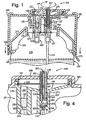
- a dispenser 120 is mounted onto can 122 via outer wall 144 that has a threaded inner surface so as to intermesh with threads on the outer surface of wall 136.
- a cover 149 extends substantially radially inwardly from the axially outer end of wall 144.
- Wall 136 has a flange at its axially inner surface that engages can chime 139.
- Wall 136 is integrally connected to an angled wall 147 that extends radially inwardly, and axially downstream, there from.
- Wall 147 is integrally connected at its radially inner edge to wall 154 that extends axially upstream and has a flange that engages rim 129.
- Control assembly 120 further includes a lever 171 that is rotated along with wall 144 to displace the control assembly 132 in the axial direction, as described above. Additionally, lever 171 could include a perforated tab (not shown) between itself and wall 144 that is broken before the dispenser can be actuated, thereby providing means for indicating whether the dispenser has been tampered with.
- Can 122 includes first and second valves 137 and 140, respectively, that extend into can 122.
- Valve 137 is connected to a conduit 133 that extends axially towards the bottom of the can so as to receive the chemical mixture.
- Valve 140 terminates in the upper region 135 of can 122 so as to receive gaseous propellant.
- Valves 137 and 140 includes a downwardly actuatable conduit 138 and 143, respectively, that extend axially out of the can 122. Accordingly, dispenser 120 may be provided as a separate part that is mountable onto can 122 by rotating wall 144 with respect to wall 136.
- active valve assembly 157 includes an annular wall 177 whose axially inner end slides over conduit 137.
- a flange 173 extends radially inwardly from wall 177, and engages the outer end of conduit 138.
- Flange 173 defines a centrally disposed channel 165 that extends axially there through and aligned with conduit 138.
- An annular wall 141 fits inside wall 177 and extends axially downstream from flange 173, and defines an axially extending conduit 175 that is in fluid communication with channel 165.
- Channel 165 extends out the dispenser 120 to provide an outlet 167 to the ambient environment.
- Wall 141 further defines a second channel 152 that extends axially between a propellant outlet vent 156 and the ambient environment
- a plug 164 is disposed between channels 175 and 165, and blocks channel 165 so as to prevent the active chemical from exiting from the dispenser 120 when not in the spray phase.
- a pair of o-rings 163 are disposed between the inner surface of wall 177 and the outer surface of wall 141 to further ensure that no active chemical or propellant is able to exit dispenser 120 through vent 156 that extends through wall 141.
- An annular channel 153 surrounds plug 164 and joins channels 165 and 175 in fluid communication during the spray phase, as will be described in more detail below.
- the propellant valve assembly 151 includes an annular wall 179 defining a conduit 142 that extends axially from valve stem 143 into an accumulation chamber 146.
- Accumulation chamber is defined by a diaphragm 150 that extends radially from a wall 161 that is disposed at the interface between cover 149 and the axially outer end of wall 179, axially inner portion of wall 161, inner surface of wall 179, and outer surface of wall 141.
- Diaphragm 150 is further connected at its radially inner end to wall 141.
- Wall 179 includes a flange 159, similar to flange 173 of wall 177, that engages valve stem 143, and defines a channel 181 extending there through that joins valve stem 143 and conduit 142 in fluid communication.
- a porous flow control media 158 is disposed within channel 142 axially downstream from flange 159 so as to regulate the flow of propellant into accumulation chamber 146.
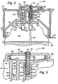
- conduit 138 or 143 When the dispenser 120 is initially mounted onto can 122, neither conduit 138 or 143 are actuated. However, referring now to FIG. 2, once the dispenser 120 is rotated to the "ON" position, thereby beginning the accumulation phase, flanges 159 and 173 are translated axially upstream and depress valve stems 143 and 138, respectively. Active chemical thus travels through conduit 133, valve 137, and into conduit 165. The active is prevented, however, from flowing into conduit 175 by the seal provided by plug 164 and o-rings 163.
- the propellant travels through valve 140, channel 181, porous media 158, conduit 142, and into accumulation chamber 146. Once the pressure of propellant acting on the axially inner surface of diaphragm 150 exceeds a predetermined threshold, the diaphragm becomes deformed from the normal closed position illustrated in FIG. 9 to the open position illustrated in FIG. 4.
- propellant travels from accumulation chamber 164 through the gap formed between the radially inner surface of wall 177 and the radially outer surface of wall 141 along the direction of arrow O, through channel 156, and into channel 152 where it exits the dispenser as a separate stream.
- the diaphragm snaps back to the closed position to begin a subsequent accumulation phase.
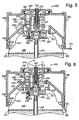
- a dispenser 220 is illustrated in accordance with the invention but having otherwise a similar construction to that described above. The primary other differences reside in the active valve assembly 257 and propellant valve assembly 251.
- the active valve assembly 257 includes an annular lip 225 that extends axially upstream into conduit 233, and defines and interior cavity 224.
- the axially upstream end of lip 225 fits inside conduit 233 to deliver active to valve 237.
- the propellant valve assembly 251 includes a flexible seal 234 extending radially outwardly from member 225 such that the axially outer surface of seal 234 rests against the axially inner surface of a seat 254.
- Seat 254 is disposed within the cup 234, and receives inner and outer fork members 259 therein.
- Fork 259 defines the axially inner end of a wall 279 that encloses a conduit 242 that flows into accumulation chamber 246.
- a porous flow control media 258 is disposed within conduit 242.
- seal 234 prevents propellant from entering channel 242.
- assembly 232 is further rotated to switch the dispenser "ON,” fork members 259 are displaced axially upstream against seal 234 which deflects outwardly away from seat 254. Because inner fork member is displaced axially downstream from outer fork member, the inlet to channel 242 is exposed to upper portion 235 of can 222, thereby enabling propellant to enter accumulation chamber 246 via conduit 242.
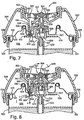
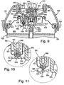
- a dispenser 520 is mounted onto a can 522 in accordance with a second embodiment.
- a more conventional container exit valve 537 extends upwardly from the center of the valve cup 527.
- the valve 537 has an upwardly extending valve stem 538, biased outwardly by a spring 569, through which the active mixture of the can 522 may be expelled.
- Valve 537 is shown as a vertically actuated valve, which can be opened by moving the valve stem 538 directly downwardly. Instead, one could use a side-tilt valve where the valve is actuated by tipping the valve stem laterally and somewhat downwardly.
- Control assembly 532 includes an outer wall 544 threaded on its inner surface that intermesh with threads of wall 536 that is connected to the can chime 539. Accordingly, the user may rotate wall 544 to switch the dispenser between the "OFF" position (FIG. 7) and the “ON” position (FIG. 8)
- Wall 544 is supported at its axially outer end by wall 552 that receives, in a groove disposed at its lower end, the upper end of a retainer wall 541.
- An o-ring 563 is disposed at the interface between walls 552 and 541.
- a monostable, flexible diaphragm 550 extends radially from the interface between the o-ring 563 and wall 552. O-ring 563 thus provides a seal to prevent gas from escaping from the accumulation chamber 546 during the accumulation phase.
- Wall 541 further includes a flange 543 extending axially downstream towards diaphragm 550.
- An inverted "L" shaped wall 561 is attached to the inner surface of diaphragm 550, and receives the axially outer end of flange 543 to prevent the escape of gas propellant during the accumulation phase.
- dispenser 520 also includes a gas propellant valve assembly 551 and an active valve assembly 557.
- the gas propellant valve assembly 551 includes wall 541, which defines a void that is occupied by a porous media 558.
- a plunger 556 having a tip 559 is disposed within a seat 554 axially upstream of the porous media 558.
- Seat 554 is affixed to the cup 527.
- Plunger 556 is annular, and defines a channel 553 extending there through at a location axially downstream from tip 559.
- Channel 535 defines the mouth of accumulation chamber 546.
- a flexible seal 534 extends radially outwardly from tee 525 such that it rests against the axially inner surface of seat 554. Two seals thus prevent the gas propellant from entering accumulation chamber 546 when the dispenser is "OFF.” Seal 534 minimizes leakage during filling of the can and provides a redundant seal to the plunger. Channel is in radial alignment with seat 554, thus forming a seal to prevent gas propellant from entering into the plunger.
- An active valve assembly 557 (see Fig. 7) includes a hub 515 that is formed from the radially inner surface of annular retainer wall 541.
- the hub defines a channel 569 through which the active mixture flows from the valve stem 538 during a spray phase.
- a plug 564 is attached to the axially inner surface of diaphragm 550, and extends axially inwardly to seal channel 569, thus preventing active chemical from exiting the dispenser 520 during the accumulation phase.
- An annular opening 567 is disposed in the diaphragm 550 at a position adjacent the plug 567 to enable active chemical to flow from the hub and out the dispenser 520 during the spray phase, as will be described below.
- the accumulation phase begins.
- wall 541 and plunger 556 are biased downwardly such that tip 559 deflects seal 534 away from the seat 554 in the direction of arrow H.
- the plunger 556 is depressed such that channel 553 is translated to a position axially upstream of seat 554, thereby permitting pressurized gas propellant to enter the channel 553 along the direction of arrow I.
- Plug 564 is biased against hub 565, which depresses valve stem 538, thereby pressurizing active chemical against the plug.
- the seal formed between the plug 564 and hub 565 prevents any active chemical from exiting the dispenser during the accumulation phase.
- the gas propellant travels through the porous media and into inlet 560 of the accumulation chamber 546.
- the constant supply of gas propellant flowing into the accumulation chamber 546 causes pressure to build therein, and such pressure acts against the inner surface of diaphragm 550.
- the mono-stable diaphragm 550 becomes deformed from the normal closed position illustrated in FIG. 28 to the open position illustrated in FIG. 9.
- the present invention provides automated dispenser assemblies for dispensing aerosol can contents without the use of repeated electric power or manual activation.
Claims (6)
- Ensemble de valve (257) qui est approprié pour distribuer un produit chimique provenant d'une bombe aérosol (222) qui comporte une première région (235) avec un gaz propulseur et une seconde région avec un produit chimique actif, l'ensemble de valve étant du type qui peut automatiquement alterner entre une phase d'accumulation où le gaz propulseur est reçu en provenance de la bombe (222), et une phase de pulvérisation où le produit chimique actif est automatiquement distribué à intervalles, l'ensemble de valve (257) comprenant :caractérisé en ce que la chambre d'accumulation (246) expulsera au moins partiellement le gaz propulseur lorsque le diaphragme (250) sera dans la seconde configuration, et le gaz propulseur et le produit chimique actif se mélangeront dans l'ensemble de valve (257) avant de sortir de l'ensemble de valve.un logement (232, 247) pouvant être monté sur une bombe aérosol (222) ;un diaphragme mobile (250) associé au logement (232, 247) et relié à un joint, le diaphragme (250) étant poussé vers une première configuration ;une chambre d'accumulation (246) à l'intérieur du logement (232, 247) pour fournir une pression variable contre le diaphragme (250) ;une première voie de passage (242) dans le logement (232, 247) appropriée pour relier la première région (235) de la bombe aérosol (222) à la chambre d'accumulation (246) ;une seconde voie de passage (265, 275) reliant la seconde région à une sortie (267) de l'ensemble de valve ;
moyennant quoi, lorsque le diaphragme (250) est dans la première configuration, le joint limite l'écoulement du produit chimique actif en dehors de l'ensemble de valve (257) ; etmoyennant quoi, lorsque la pression du gaz propulseur à l'intérieur de la chambre d'accumulation (246) dépasse un seuil spécifié, le diaphragme (250) peut se déplacer dans une seconde configuration où le produit chimique actif peut être pulvérisé depuis l'ensemble de valve (257) ; - Ensemble de valve selon la revendication 1, dans lequel le diaphragme (250) reviendra dans la première configuration depuis la seconde configuration lorsque la pression du gaz propulseur dans la chambre d'accumulation (246) tombera sous une quantité seuil.
- Ensemble de valve selon la revendication 1, dans lequel le joint peut être déplacé dans une direction axiale.
- Ensemble de valve selon la revendication 1, comprenant en outre une bombe (222) qui est reliée à l'ensemble de valve (257) où le produit chimique actif est au moins partiellement dans une phase liquide dans la bombe, et une partie d'actionnement (232) du logement (232, 247) tourne pour permettre au gaz propulseur de quitter la bombe (222) et d'entrer dans la première voie de passage (242).
- Ensemble de valve selon la revendication 1, dans lequel le produit chimique actif est sélectionné dans le groupe constitué d'insectifuges, d'insecticides, de parfums, de désinfectants et de désodorisants.
- Procédé de distribution automatique d'un produit chimique actif depuis une bombe aérosol vers un environnement ambiant à intervalles prédéterminés, le procédé comprenant les étapes consistant à :(a) prévoir un ensemble de valve (257) selon l'une quelconque des revendications précédentes,(b) monter l'ensemble de valve (257) sur une telle bombe aérosol (222) ; et(c) actionner l'ensemble de valve (257).
Applications Claiming Priority (3)
| Application Number | Priority Date | Filing Date | Title |
|---|---|---|---|
| US56873 | 2002-01-24 | ||
| US10/056,873 US6688492B2 (en) | 2002-01-24 | 2002-01-24 | Dispensing valve |
| PCT/US2003/001996 WO2003062094A1 (fr) | 2002-01-24 | 2003-01-22 | Valve de distribution d'aerosol a fonctionnement intermittent |
Publications (2)
| Publication Number | Publication Date |
|---|---|
| EP1470060A1 EP1470060A1 (fr) | 2004-10-27 |
| EP1470060B1 true EP1470060B1 (fr) | 2005-12-21 |
Family
ID=22007081
Family Applications (1)
| Application Number | Title | Priority Date | Filing Date |
|---|---|---|---|
| EP03732057A Expired - Lifetime EP1470060B1 (fr) | 2002-01-24 | 2003-01-22 | Valve de distribution d'aerosol a fonctionnement intermittent |
Country Status (9)
| Country | Link |
|---|---|
| US (2) | US6688492B2 (fr) |
| EP (1) | EP1470060B1 (fr) |
| JP (1) | JP2005518312A (fr) |
| AR (1) | AR038223A1 (fr) |
| AT (1) | ATE313496T1 (fr) |
| CA (1) | CA2473899C (fr) |
| DE (1) | DE60302874T2 (fr) |
| TW (1) | TW200302196A (fr) |
| WO (1) | WO2003062094A1 (fr) |
Cited By (1)
| Publication number | Priority date | Publication date | Assignee | Title |
|---|---|---|---|---|
| CN106927148A (zh) * | 2009-10-09 | 2017-07-07 | 索尔福德阀门有限公司 | 排放组件、液体分配仪器以及计量剂量的药物吸入器 |
Families Citing this family (36)
| Publication number | Priority date | Publication date | Assignee | Title |
|---|---|---|---|---|
| US7278590B1 (en) | 1992-02-24 | 2007-10-09 | Homax Products, Inc. | Systems and methods for applying texture material to ceiling surfaces |
| US6688492B2 (en) * | 2002-01-24 | 2004-02-10 | S.C. Johnson & Son, Inc. | Dispensing valve |
| US7500621B2 (en) | 2003-04-10 | 2009-03-10 | Homax Products, Inc. | Systems and methods for securing aerosol systems |
| US7631786B2 (en) * | 2004-03-17 | 2009-12-15 | Pepsico, Inc. | Dispenser assembly having a porous flow control member |
| EP1591377A1 (fr) * | 2004-04-20 | 2005-11-02 | Lindal Ventil GmbH | Capuchon de pulvérisation pour un récipient aérosol |
| US6971560B1 (en) * | 2004-05-14 | 2005-12-06 | S. C. Johnson & Son, Inc. | Friction resistant time delay actuator assembly for aerosol containers |
| US7213728B2 (en) * | 2004-06-24 | 2007-05-08 | S.C. Johnson & Son, Inc. | Time delay and indicator actuator assembly for aerosol containers |
| US7195139B2 (en) * | 2004-06-29 | 2007-03-27 | S.C. Johnson & Son, Inc. | Dispensing valve |
| US7677420B1 (en) | 2004-07-02 | 2010-03-16 | Homax Products, Inc. | Aerosol spray texture apparatus for a particulate containing material |
| US7487893B1 (en) | 2004-10-08 | 2009-02-10 | Homax Products, Inc. | Aerosol systems and methods for dispensing texture material |
| EP1807322B1 (fr) * | 2004-10-12 | 2008-01-09 | S.C.Johnson & Son, Inc | Pulverisateur compact |
| US8061562B2 (en) | 2004-10-12 | 2011-11-22 | S.C. Johnson & Son, Inc. | Compact spray device |
| US8344056B1 (en) | 2007-04-04 | 2013-01-01 | Homax Products, Inc. | Aerosol dispensing systems, methods, and compositions for repairing interior structure surfaces |
| US9382060B1 (en) | 2007-04-05 | 2016-07-05 | Homax Products, Inc. | Spray texture material compositions, systems, and methods with accelerated dry times |
| US8580349B1 (en) | 2007-04-05 | 2013-11-12 | Homax Products, Inc. | Pigmented spray texture material compositions, systems, and methods |
| US8590743B2 (en) | 2007-05-10 | 2013-11-26 | S.C. Johnson & Son, Inc. | Actuator cap for a spray device |
| US20080290113A1 (en) * | 2007-05-25 | 2008-11-27 | Helf Thomas A | Actuator cap for a spray device |
| US20080290120A1 (en) * | 2007-05-25 | 2008-11-27 | Helf Thomas A | Actuator cap for a spray device |
| US8469244B2 (en) * | 2007-08-16 | 2013-06-25 | S.C. Johnson & Son, Inc. | Overcap and system for spraying a fluid |
| US8381951B2 (en) * | 2007-08-16 | 2013-02-26 | S.C. Johnson & Son, Inc. | Overcap for a spray device |
| US8556122B2 (en) | 2007-08-16 | 2013-10-15 | S.C. Johnson & Son, Inc. | Apparatus for control of a volatile material dispenser |
| US8387827B2 (en) | 2008-03-24 | 2013-03-05 | S.C. Johnson & Son, Inc. | Volatile material dispenser |
| JP2009279483A (ja) * | 2008-05-20 | 2009-12-03 | Hosiden Corp | エアゾールの自動噴霧装置 |
| RU2448462C2 (ru) * | 2009-08-03 | 2012-04-27 | Федеральное государственное образовательное учреждение высшего профессионального образования "Кубанский государственный аграрный университет" | Опрыскиватель ультрамалообъемный |
| US8459499B2 (en) * | 2009-10-26 | 2013-06-11 | S.C. Johnson & Son, Inc. | Dispensers and functional operation and timing control improvements for dispensers |
| GB201006080D0 (en) * | 2010-04-13 | 2010-05-26 | Univ Salford The | Aerosol spray device |
| USD668150S1 (en) | 2010-11-09 | 2012-10-02 | S.C. Johnson & Son, Inc. | Container with retaining device |
| USD668151S1 (en) | 2010-11-26 | 2012-10-02 | S.C. Johnson & Son, Inc. | Container with retaining device |
| US8646661B2 (en) * | 2011-03-23 | 2014-02-11 | Alan Paine | Aerosol can liquid dispenser |
| US9248457B2 (en) | 2011-07-29 | 2016-02-02 | Homax Products, Inc. | Systems and methods for dispensing texture material using dual flow adjustment |
| US9156042B2 (en) | 2011-07-29 | 2015-10-13 | Homax Products, Inc. | Systems and methods for dispensing texture material using dual flow adjustment |
| US9156602B1 (en) | 2012-05-17 | 2015-10-13 | Homax Products, Inc. | Actuators for dispensers for texture material |
| US9108782B2 (en) | 2012-10-15 | 2015-08-18 | S.C. Johnson & Son, Inc. | Dispensing systems with improved sensing capabilities |
| US9435120B2 (en) | 2013-03-13 | 2016-09-06 | Homax Products, Inc. | Acoustic ceiling popcorn texture materials, systems, and methods |
| CA2859537C (fr) | 2013-08-19 | 2019-10-29 | Homax Products, Inc. | Materiaux, systemes et procedes de texture pour plafond |
| USD787326S1 (en) | 2014-12-09 | 2017-05-23 | Ppg Architectural Finishes, Inc. | Cap with actuator |
Family Cites Families (27)
| Publication number | Priority date | Publication date | Assignee | Title |
|---|---|---|---|---|
| US3305134A (en) | 1965-10-21 | 1967-02-21 | Union Carbide Corp | Automatic spray device |
| US3419189A (en) * | 1967-08-21 | 1968-12-31 | Iketani Taisho | Device for automatically and intermittently spraying pressurized products |
| US3497108A (en) | 1967-10-26 | 1970-02-24 | Dart Ind Inc | Automatic dispenser |
| US3477613A (en) | 1968-02-29 | 1969-11-11 | Dart Ind Inc | Aerosol dispenser actuated by propellant pressure |
| US3542248A (en) | 1969-01-08 | 1970-11-24 | John J Mangel | Aerosol dispenser controlled by permanent magnet |
| CA931118A (en) | 1969-07-10 | 1973-07-31 | W. Broderick Rory | Aerosol containers and valves therefor |
| US3658209A (en) | 1970-10-29 | 1972-04-25 | Gen Time Corp | Automatic cycling discharging device |
| US4077542A (en) | 1974-12-02 | 1978-03-07 | Petterson Tor H | Unattended aerosol dispenser |
| IN148848B (fr) | 1977-03-02 | 1981-06-27 | Abplanalp Robert H | |
| JPS5951344B2 (ja) * | 1979-09-03 | 1984-12-13 | 東洋エアゾ−ル工業株式会社 | エアゾ−ル用間欠噴射弁 |
| JPS5951345B2 (ja) * | 1979-09-17 | 1984-12-13 | 東洋エアゾ−ル工業株式会社 | エアゾ−ル用間欠噴射弁 |
| JPS5951346B2 (ja) * | 1979-09-17 | 1984-12-13 | 東洋エアゾ−ル工業株式会社 | エアゾ−ル用間欠噴射弁 |
| JPS5951349B2 (ja) * | 1979-11-13 | 1984-12-13 | 東洋エアゾ−ル工業株式会社 | エアゾ−ル用間欠噴射弁 |
| JPS5951347B2 (ja) * | 1979-09-17 | 1984-12-13 | 東洋エアゾ−ル工業株式会社 | エアゾ−ル用間欠噴射弁 |
| JPS57174173A (en) | 1981-04-20 | 1982-10-26 | Toyo Aerosol Kogyo Kk | Intermittent sprayer for aerosol |
| NL8901877A (nl) * | 1989-07-20 | 1991-02-18 | Airspray Int Bv | Mengkamer voor het mengen van een gasvormig en een vloeibaar bestanddeel, werkwijze voor het vormen van nauwe kanalen, en volgens deze werkwijze van nauwe kanalen voorziene lichaam of voorwerp. |
| US5018963A (en) | 1989-08-07 | 1991-05-28 | Tpv Energy System, Inc. | Pulsating gas powered light source |
| JPH0385169A (ja) | 1989-08-30 | 1991-04-10 | Showa Seiki Kk | 香料、消臭剤等の自動噴射装置 |
| JPH0385170A (ja) | 1989-08-30 | 1991-04-10 | Showa Seiki Kk | 自動噴射装置の噴射量調節機構 |
| US5025962A (en) * | 1990-01-12 | 1991-06-25 | Robert J. Leblanc | Automatic timed release spray dispenser |
| US5702036A (en) * | 1995-09-07 | 1997-12-30 | Precision Valve Corporation | Aerosol total release actuator having a delay in product emission |
| ATE215500T1 (de) | 1996-08-28 | 2002-04-15 | Kyowa Ind Co Ltd | Sprühmechanismus für aerosolprodukte |
| JP3803839B2 (ja) | 1997-02-07 | 2006-08-02 | アース製薬株式会社 | エアゾール遅延噴射装置 |
| US5791524A (en) * | 1997-05-12 | 1998-08-11 | S. C. Johnson & Son, Inc. | Total release actuator for an aerosol can |
| US6216925B1 (en) | 1999-06-04 | 2001-04-17 | Multi-Vet Ltd. | Automatic aerosol dispenser |
| JP4226736B2 (ja) | 1999-08-03 | 2009-02-18 | 東洋エアゾール工業株式会社 | エアゾール容器の遅延噴射装置 |
| US6688492B2 (en) * | 2002-01-24 | 2004-02-10 | S.C. Johnson & Son, Inc. | Dispensing valve |
-
2002
- 2002-01-24 US US10/056,873 patent/US6688492B2/en not_active Expired - Lifetime
-
2003
- 2003-01-22 CA CA002473899A patent/CA2473899C/fr not_active Expired - Fee Related
- 2003-01-22 WO PCT/US2003/001996 patent/WO2003062094A1/fr active IP Right Grant
- 2003-01-22 JP JP2003561994A patent/JP2005518312A/ja active Pending
- 2003-01-22 DE DE60302874T patent/DE60302874T2/de not_active Expired - Fee Related
- 2003-01-22 EP EP03732057A patent/EP1470060B1/fr not_active Expired - Lifetime
- 2003-01-22 AT AT03732057T patent/ATE313496T1/de not_active IP Right Cessation
- 2003-01-23 TW TW092101493A patent/TW200302196A/zh unknown
- 2003-01-24 AR ARP030100212A patent/AR038223A1/es unknown
- 2003-12-05 US US10/729,173 patent/US6837396B2/en not_active Expired - Fee Related
Cited By (2)
| Publication number | Priority date | Publication date | Assignee | Title |
|---|---|---|---|---|
| CN106927148A (zh) * | 2009-10-09 | 2017-07-07 | 索尔福德阀门有限公司 | 排放组件、液体分配仪器以及计量剂量的药物吸入器 |
| CN106927148B (zh) * | 2009-10-09 | 2019-12-03 | 索尔福德阀门有限公司 | 排放组件、液体分配仪器以及计量剂量的药物吸入器 |
Also Published As
| Publication number | Publication date |
|---|---|
| US20030136796A1 (en) | 2003-07-24 |
| DE60302874T2 (de) | 2006-07-06 |
| CA2473899C (fr) | 2007-05-08 |
| TW200302196A (en) | 2003-08-01 |
| CA2473899A1 (fr) | 2003-07-31 |
| US20040118882A1 (en) | 2004-06-24 |
| WO2003062094A1 (fr) | 2003-07-31 |
| AR038223A1 (es) | 2005-01-05 |
| US6688492B2 (en) | 2004-02-10 |
| DE60302874D1 (de) | 2006-01-26 |
| EP1470060A1 (fr) | 2004-10-27 |
| JP2005518312A (ja) | 2005-06-23 |
| ATE313496T1 (de) | 2006-01-15 |
| US6837396B2 (en) | 2005-01-04 |
Similar Documents
| Publication | Publication Date | Title |
|---|---|---|
| EP1470060B1 (fr) | Valve de distribution d'aerosol a fonctionnement intermittent | |
| EP1441965B1 (fr) | Valve de distribution a liberation totale | |
| US6478199B1 (en) | Automatic valve | |
| CA2571902C (fr) | Soupape de distribution | |
| US6588627B2 (en) | Automatic intermittent aerosol dispensing valve | |
| CA2464723C (fr) | Valve de distribution intermittente d'aerosol | |
| CA2431024C (fr) | Valve de diffusion d'aerosols | |
| AU2002340333A1 (en) | Total release dispensing valve | |
| AU2002340321A1 (en) | Automatic intermittent aerosol dispensing valve | |
| AU2002340334A1 (en) | Intermittent aerosol dispensing valve | |
| TW200404993A (en) | Total release dispensing valve |
Legal Events
| Date | Code | Title | Description |
|---|---|---|---|
| PUAI | Public reference made under article 153(3) epc to a published international application that has entered the european phase |
Free format text: ORIGINAL CODE: 0009012 |
|
| 17P | Request for examination filed |
Effective date: 20040716 |
|
| AK | Designated contracting states |
Kind code of ref document: A1 Designated state(s): AT BE BG CH CY CZ DE DK EE ES FI FR GB GR HU IE IT LI LU MC NL PT SE SI SK TR |
|
| AX | Request for extension of the european patent |
Extension state: AL LT LV MK RO |
|
| GRAP | Despatch of communication of intention to grant a patent |
Free format text: ORIGINAL CODE: EPIDOSNIGR1 |
|
| GRAS | Grant fee paid |
Free format text: ORIGINAL CODE: EPIDOSNIGR3 |
|
| GRAA | (expected) grant |
Free format text: ORIGINAL CODE: 0009210 |
|
| AK | Designated contracting states |
Kind code of ref document: B1 Designated state(s): AT BE BG CH CY CZ DE DK EE ES FI FR GB GR HU IE IT LI LU MC NL PT SE SI SK TR |
|
| PG25 | Lapsed in a contracting state [announced via postgrant information from national office to epo] |
Ref country code: IT Free format text: LAPSE BECAUSE OF FAILURE TO SUBMIT A TRANSLATION OF THE DESCRIPTION OR TO PAY THE FEE WITHIN THE PRESCRIBED TIME-LIMIT;WARNING: LAPSES OF ITALIAN PATENTS WITH EFFECTIVE DATE BEFORE 2007 MAY HAVE OCCURRED AT ANY TIME BEFORE 2007. THE CORRECT EFFECTIVE DATE MAY BE DIFFERENT FROM THE ONE RECORDED. Effective date: 20051221 Ref country code: SI Free format text: LAPSE BECAUSE OF FAILURE TO SUBMIT A TRANSLATION OF THE DESCRIPTION OR TO PAY THE FEE WITHIN THE PRESCRIBED TIME-LIMIT Effective date: 20051221 Ref country code: NL Free format text: LAPSE BECAUSE OF FAILURE TO SUBMIT A TRANSLATION OF THE DESCRIPTION OR TO PAY THE FEE WITHIN THE PRESCRIBED TIME-LIMIT Effective date: 20051221 Ref country code: SK Free format text: LAPSE BECAUSE OF FAILURE TO SUBMIT A TRANSLATION OF THE DESCRIPTION OR TO PAY THE FEE WITHIN THE PRESCRIBED TIME-LIMIT Effective date: 20051221 Ref country code: CZ Free format text: LAPSE BECAUSE OF FAILURE TO SUBMIT A TRANSLATION OF THE DESCRIPTION OR TO PAY THE FEE WITHIN THE PRESCRIBED TIME-LIMIT Effective date: 20051221 Ref country code: CH Free format text: LAPSE BECAUSE OF FAILURE TO SUBMIT A TRANSLATION OF THE DESCRIPTION OR TO PAY THE FEE WITHIN THE PRESCRIBED TIME-LIMIT Effective date: 20051221 Ref country code: LI Free format text: LAPSE BECAUSE OF FAILURE TO SUBMIT A TRANSLATION OF THE DESCRIPTION OR TO PAY THE FEE WITHIN THE PRESCRIBED TIME-LIMIT Effective date: 20051221 Ref country code: FI Free format text: LAPSE BECAUSE OF FAILURE TO SUBMIT A TRANSLATION OF THE DESCRIPTION OR TO PAY THE FEE WITHIN THE PRESCRIBED TIME-LIMIT Effective date: 20051221 Ref country code: BE Free format text: LAPSE BECAUSE OF FAILURE TO SUBMIT A TRANSLATION OF THE DESCRIPTION OR TO PAY THE FEE WITHIN THE PRESCRIBED TIME-LIMIT Effective date: 20051221 Ref country code: AT Free format text: LAPSE BECAUSE OF FAILURE TO SUBMIT A TRANSLATION OF THE DESCRIPTION OR TO PAY THE FEE WITHIN THE PRESCRIBED TIME-LIMIT Effective date: 20051221 |
|
| REG | Reference to a national code |
Ref country code: GB Ref legal event code: FG4D |
|
| REG | Reference to a national code |
Ref country code: CH Ref legal event code: EP |
|
| PG25 | Lapsed in a contracting state [announced via postgrant information from national office to epo] |
Ref country code: IE Free format text: LAPSE BECAUSE OF NON-PAYMENT OF DUE FEES Effective date: 20060123 |
|
| REG | Reference to a national code |
Ref country code: IE Ref legal event code: FG4D |
|
| REF | Corresponds to: |
Ref document number: 60302874 Country of ref document: DE Date of ref document: 20060126 Kind code of ref document: P |
|
| PG25 | Lapsed in a contracting state [announced via postgrant information from national office to epo] |
Ref country code: LU Free format text: LAPSE BECAUSE OF NON-PAYMENT OF DUE FEES Effective date: 20060131 Ref country code: MC Free format text: LAPSE BECAUSE OF NON-PAYMENT OF DUE FEES Effective date: 20060131 |
|
| PG25 | Lapsed in a contracting state [announced via postgrant information from national office to epo] |
Ref country code: GR Free format text: LAPSE BECAUSE OF FAILURE TO SUBMIT A TRANSLATION OF THE DESCRIPTION OR TO PAY THE FEE WITHIN THE PRESCRIBED TIME-LIMIT Effective date: 20060321 Ref country code: BG Free format text: LAPSE BECAUSE OF FAILURE TO SUBMIT A TRANSLATION OF THE DESCRIPTION OR TO PAY THE FEE WITHIN THE PRESCRIBED TIME-LIMIT Effective date: 20060321 Ref country code: DK Free format text: LAPSE BECAUSE OF FAILURE TO SUBMIT A TRANSLATION OF THE DESCRIPTION OR TO PAY THE FEE WITHIN THE PRESCRIBED TIME-LIMIT Effective date: 20060321 Ref country code: SE Free format text: LAPSE BECAUSE OF FAILURE TO SUBMIT A TRANSLATION OF THE DESCRIPTION OR TO PAY THE FEE WITHIN THE PRESCRIBED TIME-LIMIT Effective date: 20060321 |
|
| PG25 | Lapsed in a contracting state [announced via postgrant information from national office to epo] |
Ref country code: ES Free format text: LAPSE BECAUSE OF FAILURE TO SUBMIT A TRANSLATION OF THE DESCRIPTION OR TO PAY THE FEE WITHIN THE PRESCRIBED TIME-LIMIT Effective date: 20060401 |
|
| PG25 | Lapsed in a contracting state [announced via postgrant information from national office to epo] |
Ref country code: PT Free format text: LAPSE BECAUSE OF FAILURE TO SUBMIT A TRANSLATION OF THE DESCRIPTION OR TO PAY THE FEE WITHIN THE PRESCRIBED TIME-LIMIT Effective date: 20060522 |
|
| NLV1 | Nl: lapsed or annulled due to failure to fulfill the requirements of art. 29p and 29m of the patents act | ||
| PG25 | Lapsed in a contracting state [announced via postgrant information from national office to epo] |
Ref country code: HU Free format text: LAPSE BECAUSE OF FAILURE TO SUBMIT A TRANSLATION OF THE DESCRIPTION OR TO PAY THE FEE WITHIN THE PRESCRIBED TIME-LIMIT Effective date: 20060622 |
|
| REG | Reference to a national code |
Ref country code: CH Ref legal event code: PL |
|
| PG25 | Lapsed in a contracting state [announced via postgrant information from national office to epo] |
Ref country code: DE Free format text: LAPSE BECAUSE OF NON-PAYMENT OF DUE FEES Effective date: 20060801 |
|
| REG | Reference to a national code |
Ref country code: IE Ref legal event code: MM4A |
|
| PLBE | No opposition filed within time limit |
Free format text: ORIGINAL CODE: 0009261 |
|
| STAA | Information on the status of an ep patent application or granted ep patent |
Free format text: STATUS: NO OPPOSITION FILED WITHIN TIME LIMIT |
|
| 26N | No opposition filed |
Effective date: 20060922 |
|
| EN | Fr: translation not filed | ||
| GBPC | Gb: european patent ceased through non-payment of renewal fee |
Effective date: 20070122 |
|
| PG25 | Lapsed in a contracting state [announced via postgrant information from national office to epo] |
Ref country code: GB Free format text: LAPSE BECAUSE OF NON-PAYMENT OF DUE FEES Effective date: 20070122 |
|
| PG25 | Lapsed in a contracting state [announced via postgrant information from national office to epo] |
Ref country code: FR Free format text: LAPSE BECAUSE OF FAILURE TO SUBMIT A TRANSLATION OF THE DESCRIPTION OR TO PAY THE FEE WITHIN THE PRESCRIBED TIME-LIMIT Effective date: 20070209 |
|
| PG25 | Lapsed in a contracting state [announced via postgrant information from national office to epo] |
Ref country code: EE Free format text: LAPSE BECAUSE OF FAILURE TO SUBMIT A TRANSLATION OF THE DESCRIPTION OR TO PAY THE FEE WITHIN THE PRESCRIBED TIME-LIMIT Effective date: 20051221 |
|
| PG25 | Lapsed in a contracting state [announced via postgrant information from national office to epo] |
Ref country code: TR Free format text: LAPSE BECAUSE OF FAILURE TO SUBMIT A TRANSLATION OF THE DESCRIPTION OR TO PAY THE FEE WITHIN THE PRESCRIBED TIME-LIMIT Effective date: 20051221 |
|
| PG25 | Lapsed in a contracting state [announced via postgrant information from national office to epo] |
Ref country code: FR Free format text: LAPSE BECAUSE OF FAILURE TO SUBMIT A TRANSLATION OF THE DESCRIPTION OR TO PAY THE FEE WITHIN THE PRESCRIBED TIME-LIMIT Effective date: 20060131 |
|
| PG25 | Lapsed in a contracting state [announced via postgrant information from national office to epo] |
Ref country code: FR Free format text: LAPSE BECAUSE OF FAILURE TO SUBMIT A TRANSLATION OF THE DESCRIPTION OR TO PAY THE FEE WITHIN THE PRESCRIBED TIME-LIMIT Effective date: 20051221 Ref country code: CY Free format text: LAPSE BECAUSE OF FAILURE TO SUBMIT A TRANSLATION OF THE DESCRIPTION OR TO PAY THE FEE WITHIN THE PRESCRIBED TIME-LIMIT Effective date: 20051221 |