EP1466775A2 - Antriebskontrollapparat und Methode für Kraftfahrzeug - Google Patents
Antriebskontrollapparat und Methode für Kraftfahrzeug Download PDFInfo
- Publication number
- EP1466775A2 EP1466775A2 EP04252135A EP04252135A EP1466775A2 EP 1466775 A2 EP1466775 A2 EP 1466775A2 EP 04252135 A EP04252135 A EP 04252135A EP 04252135 A EP04252135 A EP 04252135A EP 1466775 A2 EP1466775 A2 EP 1466775A2
- Authority
- EP
- European Patent Office
- Prior art keywords
- road wheels
- section
- controlling apparatus
- motors
- parallel
- Prior art date
- Legal status (The legal status is an assumption and is not a legal conclusion. Google has not performed a legal analysis and makes no representation as to the accuracy of the status listed.)
- Withdrawn
Links
Images


Classifications
-
- E—FIXED CONSTRUCTIONS
- E04—BUILDING
- E04G—SCAFFOLDING; FORMS; SHUTTERING; BUILDING IMPLEMENTS OR AIDS, OR THEIR USE; HANDLING BUILDING MATERIALS ON THE SITE; REPAIRING, BREAKING-UP OR OTHER WORK ON EXISTING BUILDINGS
- E04G21/00—Preparing, conveying, or working-up building materials or building elements in situ; Other devices or measures for constructional work
- E04G21/12—Mounting of reinforcing inserts; Prestressing
- E04G21/122—Machines for joining reinforcing bars
- E04G21/123—Wire twisting tools
-
- B—PERFORMING OPERATIONS; TRANSPORTING
- B60—VEHICLES IN GENERAL
- B60K—ARRANGEMENT OR MOUNTING OF PROPULSION UNITS OR OF TRANSMISSIONS IN VEHICLES; ARRANGEMENT OR MOUNTING OF PLURAL DIVERSE PRIME-MOVERS IN VEHICLES; AUXILIARY DRIVES FOR VEHICLES; INSTRUMENTATION OR DASHBOARDS FOR VEHICLES; ARRANGEMENTS IN CONNECTION WITH COOLING, AIR INTAKE, GAS EXHAUST OR FUEL SUPPLY OF PROPULSION UNITS IN VEHICLES
- B60K6/00—Arrangement or mounting of plural diverse prime-movers for mutual or common propulsion, e.g. hybrid propulsion systems comprising electric motors and internal combustion engines
- B60K6/20—Arrangement or mounting of plural diverse prime-movers for mutual or common propulsion, e.g. hybrid propulsion systems comprising electric motors and internal combustion engines the prime-movers consisting of electric motors and internal combustion engines, e.g. HEVs
- B60K6/42—Arrangement or mounting of plural diverse prime-movers for mutual or common propulsion, e.g. hybrid propulsion systems comprising electric motors and internal combustion engines the prime-movers consisting of electric motors and internal combustion engines, e.g. HEVs characterised by the architecture of the hybrid electric vehicle
- B60K6/44—Series-parallel type
-
- B—PERFORMING OPERATIONS; TRANSPORTING
- B25—HAND TOOLS; PORTABLE POWER-DRIVEN TOOLS; MANIPULATORS
- B25B—TOOLS OR BENCH DEVICES NOT OTHERWISE PROVIDED FOR, FOR FASTENING, CONNECTING, DISENGAGING OR HOLDING
- B25B13/00—Spanners; Wrenches
- B25B13/10—Spanners; Wrenches with adjustable jaws
- B25B13/28—Spanners; Wrenches with adjustable jaws the jaws being pivotally movable
-
- B—PERFORMING OPERATIONS; TRANSPORTING
- B26—HAND CUTTING TOOLS; CUTTING; SEVERING
- B26F—PERFORATING; PUNCHING; CUTTING-OUT; STAMPING-OUT; SEVERING BY MEANS OTHER THAN CUTTING
- B26F1/00—Perforating; Punching; Cutting-out; Stamping-out; Apparatus therefor
- B26F1/32—Hand-held perforating or punching apparatus, e.g. awls
-
- B—PERFORMING OPERATIONS; TRANSPORTING
- B60—VEHICLES IN GENERAL
- B60K—ARRANGEMENT OR MOUNTING OF PROPULSION UNITS OR OF TRANSMISSIONS IN VEHICLES; ARRANGEMENT OR MOUNTING OF PLURAL DIVERSE PRIME-MOVERS IN VEHICLES; AUXILIARY DRIVES FOR VEHICLES; INSTRUMENTATION OR DASHBOARDS FOR VEHICLES; ARRANGEMENTS IN CONNECTION WITH COOLING, AIR INTAKE, GAS EXHAUST OR FUEL SUPPLY OF PROPULSION UNITS IN VEHICLES
- B60K6/00—Arrangement or mounting of plural diverse prime-movers for mutual or common propulsion, e.g. hybrid propulsion systems comprising electric motors and internal combustion engines
- B60K6/20—Arrangement or mounting of plural diverse prime-movers for mutual or common propulsion, e.g. hybrid propulsion systems comprising electric motors and internal combustion engines the prime-movers consisting of electric motors and internal combustion engines, e.g. HEVs
- B60K6/50—Architecture of the driveline characterised by arrangement or kind of transmission units
- B60K6/52—Driving a plurality of drive axles, e.g. four-wheel drive
-
- B—PERFORMING OPERATIONS; TRANSPORTING
- B60—VEHICLES IN GENERAL
- B60L—PROPULSION OF ELECTRICALLY-PROPELLED VEHICLES; SUPPLYING ELECTRIC POWER FOR AUXILIARY EQUIPMENT OF ELECTRICALLY-PROPELLED VEHICLES; ELECTRODYNAMIC BRAKE SYSTEMS FOR VEHICLES IN GENERAL; MAGNETIC SUSPENSION OR LEVITATION FOR VEHICLES; MONITORING OPERATING VARIABLES OF ELECTRICALLY-PROPELLED VEHICLES; ELECTRIC SAFETY DEVICES FOR ELECTRICALLY-PROPELLED VEHICLES
- B60L15/00—Methods, circuits, or devices for controlling the traction-motor speed of electrically-propelled vehicles
- B60L15/20—Methods, circuits, or devices for controlling the traction-motor speed of electrically-propelled vehicles for control of the vehicle or its driving motor to achieve a desired performance, e.g. speed, torque, programmed variation of speed
- B60L15/2036—Electric differentials, e.g. for supporting steering vehicles
-
- B—PERFORMING OPERATIONS; TRANSPORTING
- B60—VEHICLES IN GENERAL
- B60L—PROPULSION OF ELECTRICALLY-PROPELLED VEHICLES; SUPPLYING ELECTRIC POWER FOR AUXILIARY EQUIPMENT OF ELECTRICALLY-PROPELLED VEHICLES; ELECTRODYNAMIC BRAKE SYSTEMS FOR VEHICLES IN GENERAL; MAGNETIC SUSPENSION OR LEVITATION FOR VEHICLES; MONITORING OPERATING VARIABLES OF ELECTRICALLY-PROPELLED VEHICLES; ELECTRIC SAFETY DEVICES FOR ELECTRICALLY-PROPELLED VEHICLES
- B60L3/00—Electric devices on electrically-propelled vehicles for safety purposes; Monitoring operating variables, e.g. speed, deceleration or energy consumption
- B60L3/10—Indicating wheel slip ; Correction of wheel slip
- B60L3/102—Indicating wheel slip ; Correction of wheel slip of individual wheels
-
- B—PERFORMING OPERATIONS; TRANSPORTING
- B60—VEHICLES IN GENERAL
- B60L—PROPULSION OF ELECTRICALLY-PROPELLED VEHICLES; SUPPLYING ELECTRIC POWER FOR AUXILIARY EQUIPMENT OF ELECTRICALLY-PROPELLED VEHICLES; ELECTRODYNAMIC BRAKE SYSTEMS FOR VEHICLES IN GENERAL; MAGNETIC SUSPENSION OR LEVITATION FOR VEHICLES; MONITORING OPERATING VARIABLES OF ELECTRICALLY-PROPELLED VEHICLES; ELECTRIC SAFETY DEVICES FOR ELECTRICALLY-PROPELLED VEHICLES
- B60L50/00—Electric propulsion with power supplied within the vehicle
- B60L50/10—Electric propulsion with power supplied within the vehicle using propulsion power supplied by engine-driven generators, e.g. generators driven by combustion engines
- B60L50/11—Electric propulsion with power supplied within the vehicle using propulsion power supplied by engine-driven generators, e.g. generators driven by combustion engines using DC generators and DC motors
-
- B—PERFORMING OPERATIONS; TRANSPORTING
- B60—VEHICLES IN GENERAL
- B60L—PROPULSION OF ELECTRICALLY-PROPELLED VEHICLES; SUPPLYING ELECTRIC POWER FOR AUXILIARY EQUIPMENT OF ELECTRICALLY-PROPELLED VEHICLES; ELECTRODYNAMIC BRAKE SYSTEMS FOR VEHICLES IN GENERAL; MAGNETIC SUSPENSION OR LEVITATION FOR VEHICLES; MONITORING OPERATING VARIABLES OF ELECTRICALLY-PROPELLED VEHICLES; ELECTRIC SAFETY DEVICES FOR ELECTRICALLY-PROPELLED VEHICLES
- B60L50/00—Electric propulsion with power supplied within the vehicle
- B60L50/10—Electric propulsion with power supplied within the vehicle using propulsion power supplied by engine-driven generators, e.g. generators driven by combustion engines
- B60L50/16—Electric propulsion with power supplied within the vehicle using propulsion power supplied by engine-driven generators, e.g. generators driven by combustion engines with provision for separate direct mechanical propulsion
-
- B—PERFORMING OPERATIONS; TRANSPORTING
- B60—VEHICLES IN GENERAL
- B60L—PROPULSION OF ELECTRICALLY-PROPELLED VEHICLES; SUPPLYING ELECTRIC POWER FOR AUXILIARY EQUIPMENT OF ELECTRICALLY-PROPELLED VEHICLES; ELECTRODYNAMIC BRAKE SYSTEMS FOR VEHICLES IN GENERAL; MAGNETIC SUSPENSION OR LEVITATION FOR VEHICLES; MONITORING OPERATING VARIABLES OF ELECTRICALLY-PROPELLED VEHICLES; ELECTRIC SAFETY DEVICES FOR ELECTRICALLY-PROPELLED VEHICLES
- B60L50/00—Electric propulsion with power supplied within the vehicle
- B60L50/50—Electric propulsion with power supplied within the vehicle using propulsion power supplied by batteries or fuel cells
- B60L50/60—Electric propulsion with power supplied within the vehicle using propulsion power supplied by batteries or fuel cells using power supplied by batteries
- B60L50/61—Electric propulsion with power supplied within the vehicle using propulsion power supplied by batteries or fuel cells using power supplied by batteries by batteries charged by engine-driven generators, e.g. series hybrid electric vehicles
-
- Y—GENERAL TAGGING OF NEW TECHNOLOGICAL DEVELOPMENTS; GENERAL TAGGING OF CROSS-SECTIONAL TECHNOLOGIES SPANNING OVER SEVERAL SECTIONS OF THE IPC; TECHNICAL SUBJECTS COVERED BY FORMER USPC CROSS-REFERENCE ART COLLECTIONS [XRACs] AND DIGESTS
- Y02—TECHNOLOGIES OR APPLICATIONS FOR MITIGATION OR ADAPTATION AGAINST CLIMATE CHANGE
- Y02T—CLIMATE CHANGE MITIGATION TECHNOLOGIES RELATED TO TRANSPORTATION
- Y02T10/00—Road transport of goods or passengers
- Y02T10/60—Other road transportation technologies with climate change mitigation effect
- Y02T10/62—Hybrid vehicles
-
- Y—GENERAL TAGGING OF NEW TECHNOLOGICAL DEVELOPMENTS; GENERAL TAGGING OF CROSS-SECTIONAL TECHNOLOGIES SPANNING OVER SEVERAL SECTIONS OF THE IPC; TECHNICAL SUBJECTS COVERED BY FORMER USPC CROSS-REFERENCE ART COLLECTIONS [XRACs] AND DIGESTS
- Y02—TECHNOLOGIES OR APPLICATIONS FOR MITIGATION OR ADAPTATION AGAINST CLIMATE CHANGE
- Y02T—CLIMATE CHANGE MITIGATION TECHNOLOGIES RELATED TO TRANSPORTATION
- Y02T10/00—Road transport of goods or passengers
- Y02T10/60—Other road transportation technologies with climate change mitigation effect
- Y02T10/64—Electric machine technologies in electromobility
-
- Y—GENERAL TAGGING OF NEW TECHNOLOGICAL DEVELOPMENTS; GENERAL TAGGING OF CROSS-SECTIONAL TECHNOLOGIES SPANNING OVER SEVERAL SECTIONS OF THE IPC; TECHNICAL SUBJECTS COVERED BY FORMER USPC CROSS-REFERENCE ART COLLECTIONS [XRACs] AND DIGESTS
- Y02—TECHNOLOGIES OR APPLICATIONS FOR MITIGATION OR ADAPTATION AGAINST CLIMATE CHANGE
- Y02T—CLIMATE CHANGE MITIGATION TECHNOLOGIES RELATED TO TRANSPORTATION
- Y02T10/00—Road transport of goods or passengers
- Y02T10/60—Other road transportation technologies with climate change mitigation effect
- Y02T10/70—Energy storage systems for electromobility, e.g. batteries
-
- Y—GENERAL TAGGING OF NEW TECHNOLOGICAL DEVELOPMENTS; GENERAL TAGGING OF CROSS-SECTIONAL TECHNOLOGIES SPANNING OVER SEVERAL SECTIONS OF THE IPC; TECHNICAL SUBJECTS COVERED BY FORMER USPC CROSS-REFERENCE ART COLLECTIONS [XRACs] AND DIGESTS
- Y02—TECHNOLOGIES OR APPLICATIONS FOR MITIGATION OR ADAPTATION AGAINST CLIMATE CHANGE
- Y02T—CLIMATE CHANGE MITIGATION TECHNOLOGIES RELATED TO TRANSPORTATION
- Y02T10/00—Road transport of goods or passengers
- Y02T10/60—Other road transportation technologies with climate change mitigation effect
- Y02T10/7072—Electromobility specific charging systems or methods for batteries, ultracapacitors, supercapacitors or double-layer capacitors
-
- Y—GENERAL TAGGING OF NEW TECHNOLOGICAL DEVELOPMENTS; GENERAL TAGGING OF CROSS-SECTIONAL TECHNOLOGIES SPANNING OVER SEVERAL SECTIONS OF THE IPC; TECHNICAL SUBJECTS COVERED BY FORMER USPC CROSS-REFERENCE ART COLLECTIONS [XRACs] AND DIGESTS
- Y02—TECHNOLOGIES OR APPLICATIONS FOR MITIGATION OR ADAPTATION AGAINST CLIMATE CHANGE
- Y02T—CLIMATE CHANGE MITIGATION TECHNOLOGIES RELATED TO TRANSPORTATION
- Y02T10/00—Road transport of goods or passengers
- Y02T10/60—Other road transportation technologies with climate change mitigation effect
- Y02T10/72—Electric energy management in electromobility
-
- Y—GENERAL TAGGING OF NEW TECHNOLOGICAL DEVELOPMENTS; GENERAL TAGGING OF CROSS-SECTIONAL TECHNOLOGIES SPANNING OVER SEVERAL SECTIONS OF THE IPC; TECHNICAL SUBJECTS COVERED BY FORMER USPC CROSS-REFERENCE ART COLLECTIONS [XRACs] AND DIGESTS
- Y10—TECHNICAL SUBJECTS COVERED BY FORMER USPC
- Y10S—TECHNICAL SUBJECTS COVERED BY FORMER USPC CROSS-REFERENCE ART COLLECTIONS [XRACs] AND DIGESTS
- Y10S903/00—Hybrid electric vehicles, HEVS
- Y10S903/902—Prime movers comprising electrical and internal combustion motors
- Y10S903/903—Prime movers comprising electrical and internal combustion motors having energy storing means, e.g. battery, capacitor
- Y10S903/904—Component specially adapted for hev
- Y10S903/906—Motor or generator
Definitions
- the present invention relates to vehicular drive controlling apparatus and method which are capable of driving a whole or part of road wheels of the vehicle using electric motors.
- Japanese Patent Application First Publication No. 2000-318473 published on November 21, 2000 exemplifies a previously proposed vehicular drive controlling apparatus which drives a part of a plurality of road wheels with electric motors.
- front left and right road wheels are driven by means of an engine and each of rear left and right road wheels is drive by a corresponding individual motor.
- Two motors driving the rear left and right road wheels respectively are disposed on a center portion of a vehicular width direction at a vehicular rear side, each motor being coupled to a corresponding road wheel via a corresponding speed-reduction unit.
- Power for the two motors is supplied from a (second) generator which is a power supply and an electronic control circuit controls a field current of each of the motors so as to govern an electromotive force and, furthermore, a generated driving force at each road wheel connected to the corresponding one of the two motors. Then, in the previously proposed vehicular drive controlling apparatus, the power supply as the second generator and two motors are electrically connected in parallel to each other.
- the motors driving individually and separately the respective left and right road wheels are disposed at the center portion of the vehicular width direction, the height of a floor at a rear portion accordingly becomes high.
- the two motors are electrically connected in parallel to each other with respect to the power supply, armature current values of the two motors are differed due to variations in direct current resistance values and counter electromotive forces of the respective motors. Consequently, a difference between the generated driving forces of the left and right road wheels may occur.
- the driving force difference in the left and right road wheel connected motors gives an influence to a stability during a straight travel of the vehicle.
- an object of the present invention to provide drive controlling apparatus and method for an automotive vehicle which can improve the stability in the vehicular straight run using simple means even through the pair of left and right road wheels of the vehicle are individually and separately driven by means of drive motors.
- a drive controlling apparatus for an automotive vehicle comprising: at least one couple of road wheels that constitutes one pair of parallel road wheels with respect to a vehicular width direction located on the same axis of the vehicular width direction; a plurality of motors driving independently and separately each road wheel of the pair of parallel road wheels; and a power supply to supply an electric power to the plurality of motors, the plurality of motors driving respective road wheels of the pair of parallel road wheels being enabled to constitute a serial circuit with respect to the power supply.
- a drive controlling method for an automotive vehicle comprising: providing at least one couple of road wheels that constitutes one pair of parallel road wheels with respect to a vehicular width direction located on the same axis of the vehicular width direction; providing a plurality of motors driving independently and separately each road wheel of the pair of parallel road wheels; providing a power supply supplying an electric power to the plurality of motors; and enabling the plurality of motors driving respective road wheels of the pair of parallel road wheels to constitute a serial circuit with respect to the power supply.
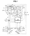
- Fig.1 is a rough configuration view of a drive controlling apparatus for an automotive vehicle in a first preferred embodiment according to the present invention.
- Fig. 2 is a configuration view representing a connection relationship between a road wheel to a corresponding motor in the first embodiment shown in Fig. 1.
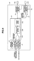
- Fig. 3 is a configuration view representing a connection state between a generator and each motor in the first embodiment shown in Fig. 1.
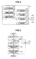
- Fig. 4 is a functional block diagram of a 4WD (four-wheel drive) controller in the first embodiment shown in Fig. 1.
- Fig. 5 is an operational flowchart representing a process of an extra torque calculating section of 4WD controller shown in Fig. 4.
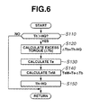
- Fig. 6 is an operational flowchart representing a process of a target torque controlling section of 4WD controller shown in Fig. 4.
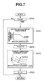
- Fig. 7 is an operational flowchart representing a process of an extra torque converting section of 4WD controller shown in Fig. 4.
- Fig. 8 is an operational flowchart executed by an engine controller shown in Fig. 1.
- Fig. 9 is a circuit block diagram of a motor controlling section in a second preferred embodiment of the drive controlling apparatus according to the present invention.
- Fig. 10 is a circuit block diagram of a motor controlling section in a third preferred embodiment of the drive controlling apparatus according to the present invention.
- Fig. 11 is a rough configuration view of a drive controlling apparatus in a fourth preferred embodiment according to the present invention.
- Fig. 12 is a configuration view representing a connection relationship between each motor and each road wheel of the vehicle to which the drive controlling apparatus in the fourth preferred embodiment is applicable.
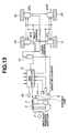
- Fig. 13 is a configuration view representing another connection relationship between each motor and each road wheel of the vehicle to which the drive controlling apparatus in the fourth preferred embodiment is applicable.
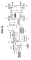
- Fig. 14 is a rough configuration view representing a fifth preferred embodiment of the drive controlling apparatus according to the present invention.
- Fig. 15 is a configuration view of a connection relationship between each motor and a corresponding road wheel in the fifth embodiment shown in Fig. 14.
- Fig. 16 is a rough configuration view of the drive controlling apparatus in a sixth preferred embodiment according to the present invention.
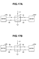
- Figs. 17A and 17B are explanatory views representing switched states of a switch box in the sixth embodiment of the drive controlling apparatus according to the present invention.
- Fig. 18 is a functional block diagram of the 4WD controller in the sixth embodiment shown in Fig. 16.
- Fig. 19 is an operational flowchart representing a process of a circuit switching control section of the 4WD controller of the drive controlling apparatus in the sixth preferred embodiment according to the present invention.
- Fig. 20 is an operational flowchart representing a process of a circuit switching control section of the 4WD controller in the seventh preferred embodiment according to the present invention.
- Fig. 1 shows a rough configuration view of a vehicular system to which a drive controlling apparatus in a first preferred embodiment according to the present invention is applicable.
- an automotive vehicle in the first embodiment has front left and right road wheels 1L and 1R driven by means of an engine (internal combustion engine) 2 and has each of rear left and right road wheels 3L and 3R driven individually and separately from each other by means of a corresponding one of drive motors 4RL and 4RR.
- drive axles of respective drive motors 4RL and 4RR are directly coupled to wheel axles of corresponding rear road wheels 3L and 3R via speed reducers 11RL and 11RR and clutches 12RL and 12RR.
- An output torque Te of engine 2 is transmitted to front left and right road wheels 1L and 1R via a transmission 30 and differential gear 31.
- a shift position detector 32 is installed on transmission 30 to detect a present gear shift range and to output a detected gear shift position signal to a 4WD (four-wheel drive) controller 8.
- a main throttle valve 15 and sub throttle valve 16 are intervened in an intake-air tubular passage 14 of engine 2 (for example, intake manifold).
- a throttle opening angle of main throttle valve 15 is adjustably controlled in accordance with a depression depth (depression quantity) of an accelerator pedal 34 which is an accelerator opening angle command unit (acceleration command operation section).
- the throttle opening angle of main throttle valve 15 is adjustably controlled by means of a mechanical interlock to the depression depth of accelerator pedal 17 or by means of an electrical adjustable control with engine controller 18 in accordance with of a depression depth (quantity) (a detection value) of an accelerator (pedal) sensor 40 to detect the depression depth (quantity) of an accelerator pedal 17.
- the depression depth detection value of accelerator sensor 40 is outputted to 4WD controller 8.
- sub throttle valve 16 is linked with an actuator to actuate sub throttle valve 16, the actuator being constituted by a stepping motor 19 so that the opening angle of sub throttle valve 16 is adjustably controlled in accordance with a revolution angle of stepping motor 19 which accords with a number of steps in stepping motor 19.
- the revolution angle of stepping motor 19 is adjustably controlled in response to a drive signal from a drive motor controller 20.
- a throttle sensor is installed on sub throttle valve 16 and on the basis of the detected value of the throttle opening angle detected by the throttle sensor, the number of steps of stepping motor 19 is feedback controlled.
- An adjustment of the throttle opening angle of sub throttle valve 16 is adjusted to be equal to or narrower than opening angle of main throttle valve 15 permits a control of an output torque of engine 2 independently of a manual operation (or manipulation) of the driver through the accelerator pedal.
- an engine speed sensor 21 is installed in engine 2 to detect an engine speed and to output a engine speed indicative signal to engine controller 18 and 4WD controller 8.
- reference numeral 34 denotes a brake pedal, constituting a brake command operation section.
- a stroke quantity of brake pedal 34 is detected by brake stroke sensor 35.
- Brake stroke sensor 35 outputs a detected brake stroke quantity to brake controller 36 and 4WD controller 8.
- Brake controller 36 controls a braking force acted upon a vehicle in accordance with the inputted brake stroke quantity via brake units 37FL, 37FR, 37RL, and 37RR constituted by disc brakes equipped on respective road wheels 1L, 2R, 3L, and 3R.
- a part of revolution torque Te of engine 2 is transmitted to a generator 7 via an endless belt 6,and generator 7 is revolved at a number of revolution per minutes (revolution speed) Nh which is a multiplication of engine speed Ne of engine 2 with a pulley ratio.
- Generator 7 is equipped with a voltage regulator 22 (regulator) to adjust an output voltage V thereof.
- 4WD controller 8 controls a generator control command value c1 (namely, a pulse duty ratio) so that a field current 1fh causes a generator load torque Th and generated voltage V to be controlled. That is to say, voltage regulator 22 receives generator control command c1 (or a value of the field current) from 4WD controller 8, adjusts field current 1fh to a value which accords with generator control command c1 and is enabled to output the detected value of output voltage V to 4WD controller 8.
- the number of revolutions per minutes Nh (revolution speed) of generator 7 can be calculated on the basis of the pulley ratio of engine speed Ne of engine 2.
- a power generated by means of its generator 7 is enabled to be supplied to two drive motors 4RL and 4RR via electric wire 9.
- Two motors 4RL and 4RR are serially connected as shown in Fig.3.
- a junction box 10 is disposed in a midway through electric wire 9.
- a current sensor 23 is installed within junction box 10.
- Current sensor 23 detects a current value Ia flowing through electric wire 9 of the power supplied to two drive motors 4RL and 4RR from generator 7 and outputs an detected armature current signal to 4WD controller 8.
- a voltage value (voltage across drive motors 4RL and 4RR) through electric wire 9 is detected by 4WD controller 8.
- reference numeral 24 denotes a relay and, via relay 24, a command issued from 4WD controller 8 serves to control an interruption and connection of the voltage (or current) supplied to drive motors 4RL and 4RR.
- field currents of two drive motors 4RL and 4RR are individually and separately controlled in accordance with the command from 4WD controller 8 and an adjustment of each field current causes the corresponding one of the drive motors 4RL and 4RR of rear road wheels 3L and 3R to be adjusted.
- a revolution speed sensor 26 to detect a revolution speed (revolution per minutes) Nm of each of two drive motors 4RL and 4RR is provided and outputs a detected revolution speed signal of the corresponding one of the drive motors 4RL and 4RR to 4WD controller 8.
- Drive motor revolution sensor 26 is constituted by input axle revolution speed detecting means (section).
- each clutch 12 is constituted by a hydraulic clutch or electromagnetic clutch and is in either a clutched (or connection) state or an interruption state in accordance with a clutch command issued from 4WD controller 8. Then, each road wheel 1L, 1R, 3L, and 3R is provided with a road wheel speed sensor 27FL, 27FR, 27RL, and 27RR. A pulse train signal in accordance with a corresponding one of the revolution speeds of the respective road wheels 1L, 1R, 3L, and 3R.
- 4WD controller 8 functionally includes: a generator control section 8A; a relay control section 8B: a motor control section 8C; a clutch control section 8D; an extra torque calculating section 8E; a target torque control section 8F; and an extra torque converting section 8G.
- Generator control section 8A outputs a generator command value c1 for generator 7 so as to adjust a field current Ifh while monitoring generated voltage V through voltage regulator 22.
- Relay control section 8B controls an interruption or connection of a power supply to drive motors 4RL and 4RR from generator 7.
- Clutch control section 8D controls states of clutches 12RL and 12RR by outputting a clutch control command to clutches 12RL and 12RR.
- the process is circulated in an order of extra torque calculating section 8E, target torque limiting section 8F, and an extra torque converting section 8G.
- extra torque calculating section 8E carries out such a process as described with reference to a flowchart of Fig. 5. That is to say, at a step S10, extra torque calculating section 8E subtracts road wheel velocities of rear road wheels 3L and 3R (non-driven wheels) from road wheel velocities of front road wheels 1L and 1R (main driven wheels) to derive slip velocity ⁇ VF which is an acceleration slip quantity of each front road wheel 1L and 1R and the routine shown in Fig. 5 goes to a step S20.
- derived slip quantity ⁇ VF is larger than a predetermined value, for example, zero.
- step S20 If ⁇ VF ⁇ 0 (No) at step S20, the routine goes to a step S30 since extra torque calculating section 8E estimates that front road wheels 1L and 1R are not in the acceleration slip state. At step S30, zero is substituted into Th (as will be described later) and the routine is returned to step S10. On the other hand, if ⁇ VF > 0 (Yes) at step S20, since either of front road wheels 1L or 1R is under an acceleration slip condition, the routine goes to a step S40. At step S40, extra torque calculating section 8E calculates an absorption torque T ⁇ VF required to suppress an acceleration slip of front road wheels 1L and 1R using the following equation and the routine goes to a step S50.
- extra toque calculating section 8E calculates a load torque TG of the present generator 7 on the basis of the following equation and the routine goes to a step S60.
- TG K2 x V K 3 x Ia Nh wherein V denotes voltage across generator 7, Ia denotes an armature current flowing through generator 7, Nh denotes a revolution speed of generator 7, K3 denotes a predetermined efficiency, and K2 denotes a predetermined coefficient.
- extra torque calculating section 8E calculates the extra torque, viz., a target load torque Th to be loaded by generator 7 and the routine is returned to step S10.
- Th TG + T ⁇ VF
- target torque limiting section 8F determines whether target generator load torque Th is larger than a maximum load capacity HQ of generator 8. If target torque limiting section 8F determines that target generator load torque Th is equal to or below maximum load capacity HQ, the routine is returned the original step, namely, step S110. If target torque limiting section 8F determines that target generator load torque Th is larger than maximum load capacity HQ of generator 7 (Yes), the routine goes to a step S120.
- an extra torque ⁇ Tb is determined which exceeds maximum load capacity HQ at target generator load torque Th using the following equation and the routine goes to a step S130.
- ⁇ Tb Th - HQ
- extra torque calculating section 8E calculates a present engine speed Te on the basis of signals outputted from engine speed sensor 21 and throttle sensor.
- extra torque converting section 8G determines if target generator load torque Th is larger than zero (0). If Th ⁇ 0 (No) at step S200, the routine is returned to the same step. If Th > 0 (Yes) at step S200, the acceleration slip occurs at each of front road wheels 1L and 1R and the routine goes to a step S220.
- extra torque converting section 8G inputs revolution speed Nm of each of drive motors 4RL and 4RR detected by means of drive motor revolution speed sensor 21, calculates a target drive motor field current Ifm in accordance with revolution speed Nm of each of drive motors 4RL and 4RR, and outputs target drive motor field current Ifm to an electric motor control section 8C. Then, the routine goes to a step S230.
- target drive motor field current Ifm with respect to revolution speed Nm of drive motors 4RL and 4RR provides a constant predetermined current value in a case where revolution speed Nm is equal to or lower than a predetermined revolution speed. If either of drive motors 4RL and 4RR is equal to or higher than a predetermined revolution speed, a well-known field weakening control causes field current Ifm to be made smaller. That is to say, since the drive motor torque is reduced due to a rise in an induced voltage E of drive motors 4RL and 4RR when drive motors 4RL and 4RR are revolved at high speeds, as described above, field current Ifm is made small to reduce an induced voltage E when revolution speed Nm of each of drive motors 4RL and 4RR becomes high.
- drive motors 4RL and 4RR give high-speed revolutions so as to suppress a rise in induced voltage E of drive motors 4RL and 4RR.
- a reduction of drive motor torque is suppressed.
- a required drive motor torque can be obtained.
- a two-stage control between lower than a predetermined engine speed and a predetermined revolution speed or higher can be achieved.
- a control purpose electronic circuit can be inexpensive as compared with a continuous field current control.
- a drive motor torque correcting section may be installed in which field current Ifm is adjusted in accordance with revolution speeds Nm of drive motors 4RL and 4RR with respect to a required drive motor torque so that the drive motor torque is continuously corrected. That is to say, field current Ifm of each drive motor 4RL and 4RR may be adjusted in accordance with revolution speed Nm of the corresponding one of drive motors 4RL and 4RR for the two-stage switching. Consequently, even if drive motors 4RL and 4RR are revolved at high speeds, a rise in induced voltage E of each drive motor 4RL and 4RR is suppressed and the reduction in drive motor torque is suppressed. Hence, a required drive motor torque can be obtained. In addition, since a smooth drive motor torque characteristic can be obtained, the vehicle can be stabilized during the vehicular run as compared with the two stage control and a drive efficiency of each of drive motors 4RL and 4RR can always be in a favorable state.
- extra torque converting section 8E calculates a target drive motor torque Tm(n) corresponding to a map on the basis of target generator load torque Th calculated by extra torque calculating section 8E and the routine goes to a step S240.
- torque converting section 8E calculates a corresponding target armature current Ia on the basis of a map with target drive motor torque Tm(n) and target drive motor field current Ifm as parameters.
- extra torque converting section 8E is returned after extra torque converting section 8E calculates pulse signal duty ratio c1 which is a generator control command value on the basis of target armature current Ia and outputs duty ratio c1 and the routine is returned to step S200.
- Motor controlling section 8C adjusts field currents Ifm of respective two motors 4RL and 4RR so as to coincide with target drive motor field current Ifm derived by extra torque converting section. Consequently, the torques of two drive motors 4RL and 4RR are respectively adjusted so that torques of drive motors 4RL and 4RR are adjusted to required values.
- Engine controller 18 performs the processing as shown in a flowchart of Fig. 8 on the basis of the input respective signals. That is to say, at a step S610, engine controller 18 calculates a target output torque TeN that the driver has requested on the basis of a detection signal from accelerator sensor 40 and the routine goes to a step S620.
- step S620 4WD controller 8 determines whether an input of a limit output torque TeM from 4WD controller 8 is present or not. If the input of TeM is present (Yes), the routine goes to a step S630. On the other hand, if no input of limit output torque TeM is present (No) at step S620, the routine goes to a step S670.
- step S630 engine controller 8 determines whether target output torque TeN is larger than a limit output torque TeM. If target output torque TeN is larger than limit output torque TeM, the routine goes to a step S640. On the other hand, if target output torque TeN is equal to or smaller than limit output torque TeM, the routine goes to step S670. At step S640, engine controller 8 substitutes limit output torque TeM into target output torque TeN to decrease target output torque TeN and the routine goes to step S370. At step S670, engine controller 8 calculates the present output torque Te on the basis of throttle opening angle and engine revolution speed and the routine goes to a step S680.
- step S680 engine controller 8 outputs a deviation ⁇ Te' between target output torque TeN with respect to a present output torque Te on the basis of the following equation and the routine goes to a step S690.
- ⁇ Te' TeN - Te
- step 5690 engine controller 8 calculates a variation of ⁇ of throttle opening angle ⁇ and outputs the opening angle signal corresponding to variation ⁇ of the throttle valve to stepping motor 19 and the routine is returned to step S610.
- a torque transmitted from engine 2 to front road wheels 1L and 1R is larger than a road surface reactive force limit torque transmitted to front road wheels 1L and 1R, viz., if front road wheels 1L and 1R which are main drive wheels are acceleration slips, each clutch 12RL and 12RR is connected and generator 7 is generated at generator load torque Th which accords with the acceleration slip quantity.
- the vehicle is transferred to a four wheel drive (4WD) state.
- each front road wheel 1L and 1R is adjusted to approach to a road surface reaction limit torque of front road wheels 1L and 1R so that the vehicle falls in a two wheel drive (2WD) state. Consequently, the acceleration slip is suppressed on front road wheels 1L and 1R which are main drive wheels.
- drive motors 4RL and 4RR are driven by means of extra power generated by generator 7 and non-driven wheels of rear road wheels 3L and 3R are driven.
- a vehicular acceleration characteristic is improved.
- drive motors 4RL and 4RR are driven by means of extra torque exceeding the road surface reactive force limit torque of main driven wheels 1L and 1R, the energy efficiency is improved and a fuel consumption is improved.
- the armature current is supplied to left and right road wheels 4RL and 4RR from generator 7 which is a common power supply.
- generator 7 which is a common power supply.
- the armature current of left and right drive motors 4RL and 4RR is mutually the same so that a drive torque of left and right drive motors 4RL and 4RR has the same value and, furthermore, driving forces developed at left and right road wheels driven by means of the respective drive motors 4RL and 4RR becomes mutually the same value.
- left and right drive motors 4RL and 4RR are disposed in proximities of the corresponding road wheels, viz., as the result of the fact that two drive motors 4RL and 4RR are not disposed at a center portion of the vehicle,viz., a floor space, with a floor located at a rear side of a vehicle body lowered, can be enlarged.
- left and right drive motors 4RL and 4RR may be disposed at the center portion in a vehicular width direction.
- rear left and right road wheels 3L and 3R are driven in a case where the front wheels are in the acceleration slip state.
- the present invention is applicable to a system where the drive state is transferred to the 4WD state in accordance with the accelerator opening angle.
- a 4WD switch may be provided, 4WD switch being capable of switching the drive state of the vehicle between the 2WD (two-wheel drive) state and 4WD (four-wheel drive) state. That is to say, the driving control of drive motors 4RL and 4RR is not limited to the above-described control.
- drive motors 4RL and 4RR are driven by a voltage V developed by generator 7 so as to constitute the 4WD state, in the first embodiment.
- the present invention is not limited to this.
- the present invention is applicable to a system in which a common battery which is capable of supplying the power to two drive motors 4RL and 4RR.
- the electrical power may be supplied from both of the battery and the generator.
- a motor may be constituted by the main drive source.
- a second preferred embodiment of the drive controlling apparatus will be described with reference to the drawings.
- the same reference numerals as those described in the first embodiment designate the like elements in the second embodiment.
- a basic structure in the second embodiment is generally the same as described in the first embodiment.
- a difference point is a process of motor controlling section 8C.
- Motor controlling section 8C in the second embodiment includes: an operation determining section 50; a target yaw rate detecting section 51; an actual yaw rate detecting section 52; deviation calculating section 53; a polarity inverting amplifier 54; a rear left road wheel controlling section 55; and a rear right road wheel controlling section 56.
- Deviation calculating section 53 constitutes a driving force difference detecting section (means).
- Polarity inverting amplifier 54, rear left road wheel controlling section 55, and rear right road wheel controlling section 56 constitute a field current correcting section (means).
- Operation determining section 50 determines whether a field current command value for each of two drive motors 4RL and 4RR should be corrected or not. When operation determining section determines that conditions described in items of 1 ⁇ through 3 ⁇ are satisfied, the correction for the field current command value is carried out and the operation determining section 50 outputs activation commands to target yaw rate detecting section 51 and actual yaw rate detecting section 52. In addition, when at least one of the following conditions of 1 ⁇ through 3 ⁇ is not satisfied, operation determining section 50 issues a stop command.
- a forced brake control such as a TCS (Traction Control System) control is not carried out; and (3) A steering angle of the steering wheel is in a proximity to zero, in other words, an absolute value of the steering wheel falls within a predetermined angle.
- a predetermined angle indicates within an operating variable of the steering wheel that the vehicle driver instructs the vehicle to make a straight run.
- target yaw rate detecting section 51 starts the operation to input the activation command, inputs the detection value of the steering angle from steering angle sensor, inputs the vehicle speed from the vehicle speed sensor, and calculates a target yaw rate by means of a well known calculation.
- the calculated yaw rate is continuously outputted to deviation calculating section 53.
- actual yaw rate detecting section 52 outputs actual yaw rate value to deviation calculating section 53 on the basis of the signal derived from yaw rate sensor.
- Deviation calculating section 50 calculates a deviation between the inputted target yaw rate and the actual yaw rate, outputs directly a value in accordance with the deviation quantity to rear left road wheel controlling section 55, and polarity inverting amplifier 54 inverts the polarity of the value which accords with the deviation quantity, and the inverted value is supplied to rear right road wheel controlling section 56.
- deviation calculating section 53 includes: an operational amplifier 53A having two positive and negative input ends; an integration circuit 53B; and a sample/hold circuit 53C.
- Operational amplifier 53A determines a deviation quantity with a plus value in a case where the actual yaw rate has the tendency of a right turn rather than the target yaw rate and a minus value in a case where the actual yaw rate has the tendency of a left turn rather than the target yaw rate. Subsequently, integration circuit 53B eliminates AC components using a filter having a time constant of about one second.
- a sample/hold circuit 53C serves to process a hold of a value immediately before the integration in a case where the vehicular road wheel slip occurs or the steering angle is equal to or wider than a predetermined steering angle.
- rear left road wheel controlling section 55 controls the drive motor field current in such a way that an addition value of target drive motor field current Ifm derived by extra torque converting section 8G into a deviation value inputted from deviation calculating section 53 to target drive motor field current Ifm so as to give the motor field current of each of rear left road wheel drive motor 4RL.
- rear right road wheel controlling section 56 controls the motor field current in such a way that an addition value of target drive motor field current Ifm derived by extra torque converting section 8G into a deviation value inputted from deviation calculating section 53 to target drive motor field current Ifm so as to give the motor field current of each of rear right road wheel drive motor 4RR.
- the drive torques of left and right road wheel drive motors 4RL and 4RR should be equal. However, due to differences in the mechanical efficiency and magnetic field efficiency, the difference in the drive torques between the left and right drive motors 4RL and 4RR may occur.
- a value in accordance with the generated driving force differences of the left and right drive motors 4RL and 4RR and the field current value of each of left and right drive motors 4RL and 4RR is accordingly corrected in such a direction toward which the deviation becomes small. Hence, the stability in the straight run of the vehicle is improved.
- the correction of the field current is carried out during a vehicular run in a grip range without execution of the TCS control so that an influence of an unbalance between the left and right sides of a road surface frictional coefficient is not given. Furthermore, the correction of the field current is carried out only in a case where the steering angle is placed in the vicinity to zero so that the deviation is not detected due to the yaw rate during the turning.
- the correction of the field current is corrected in such a way that the absolute value of the correction quantity of the field current has the same value as those of the left and right drive motors 4RL and 4RR so that a variation of the field current does not change the sum of the terminal voltages between the two motors.
- the correction value of the left and right field currents is the polarity of one value inverted. Hence, the calculation is easy.
- the other structure, action, and advantage are the same as those described in the first embodiment.
- Motor controlling section 8C includes operation determining section 50, a right road wheel drive torque calculating section 61, left road wheel drive torque calculating section 62, deviation calculating section 53, polarity inverting amplifier 54, rear left road wheel controlling section 55, and rear right road wheel controlling section 56.
- Right road wheel drive torque calculating section 61 calculates the drive torque of rear right road wheels 3L and 3R on the basis of signals outputted from a torque sensor installed on left drive motor 4RL and outputs a signal indicating the result of the calculation to operational amplifier 58A.
- Operational amplifier 53A outputs the deviation with a plus value when right road wheel drive torque is large and outputs the deviation with a minus value when left road wheel drive torque is large.
- the other structure of the drive controlling apparatus in the third embodiment is the same as motor controlling section 8C in the second embodiment.
- the value in accordance with the deviation in the developed driving force of the left and right road wheels is calculated and the field current values of left and right road wheels 4RL and 4RR are respectively corrected so as to reduce the deviation (drive torque difference between the left and right driven wheels).
- the action and advantage of the third embodiment are generally the same as those described in the second embodiment.
- FIG. 11 shows a rough configuration view of the drive controlling apparatus in the fourth embodiment.
- the front left and right road wheels are separately and individually drivable by means of drive motors 4FL and 4FR described in the first embodiment.
- the power can be supplied from generator 7 for the four drive motors 4RL, 4RR, 4FL, and 4FR.
- four drive motors 4RL, 4RR, 4FL, and 4FR are electrically serially connected with one another with respect to generator 7 which is a common power supply.
- 4WD controller 8 causes generator 7 to be generated in accordance with the accelerator opening angle and, on the basis of the signal from 4WD switch, the connection to or disconnection from the rear left and right drive clutches is carried out.
- main driven wheels which are front road wheels.
- the main driven wheels driven in the two-wheel drive state may be rear road wheels 3L and 3R.
- a front road-wheel and rear road-wheel switch may be installed so that, in accordance with a situation, the road wheels driven during the two-wheel drive may be switched to front or rear road wheels 3L and 3R.
- the correction of the field current value between the road wheels which provide pairs of the left and right road wheels is carried out.
- the correction of the field current value between the front left and right road wheels is carried out independently of the correction of the field current between the rear left and right road wheels.
- all of four wheel drive motors 4RL, 4RR, 4FL, and 4FR are serially connected to generator 7.
- the electrical serial connection may be carried out at least between the road wheels which constitute the pair.
- two drive motors 4RL and 4RR which correspond to left and right road wheels 3L and 3R are serially connected.
- Two drive motors 4RL and 4RR which correspond to rear left and right road wheels 3L and 3R may be connected in parallel to the other two drive motors 4RL and 4RR which correspond to rear left and right road wheels 3L and 3R.
- the stability of the straight run of the vehicle is improved even though the drive control through drive motors 4FL and 4FR of front left and right road wheels are drivingly controlled.
- the power supply for rear left and right road wheel drive motors 4RL and 4RR and that for the front left and right road wheels 4RL and 4RR provide the common power supply.
- the power supply of the rear left and right road Wheel drive motors 4RL and 4RR may be separated from that of front left and right road wheel drive motors 4FL and 4FR.
- the motors driving the road wheels which are opposed in the pair may serially be connected to their common power supply.
- FIG. 14 A basic structure of the fifth embodiment, as shown in Fig. 14, is the same as described in the fourth embodiment.
- a difference point from the fourth embodiment is that a common power supply is constituted by generator 7, a battery 70, and a current control circuit 71.
- a single current control circuit 71 is provided as a result of the fact that four drive motors 4RL, 4RR, 4FL, and 4FR are serially connected.
- the structure, action, and advantage are the same as those described in the fourth embodiment.
- Fig. 16 shows a rough configuration of the drive controlling apparatus in a sixth preferred embodiment according to the present invention.
- drive axles of respective drive motors 4RL and 4RR are directly connected to wheel axles of the corresponding rear road wheels 3L and 3R via speed reducers 11RL and 11RR and clutches 12RL and 12RR.
- the structure of the drive controlling apparatus shown in Fig. 16 is generally the same as that in the first embodiment shown in Fig. 1. Hence, only difference points from the first embodiment will be described below. That is to say, the electric power generated by generator 7 is enabled to be supplied to two drive motors 4RL and 4RR via electric wire. In a midway through electric wire 9, a junction box 10 and a switch box 41 are intervened.
- switch box 41 serves to select one of parallel connection and series connection with left and right drive motors 4RL and 4RR to generator 7.
- Each terminal of two lines 9a and 9b and 9c and 9d connected to both ends of respective armature coils of left and right drive motors 4RL and 4RR is connected to switch box 41.
- a signal from 4WD controller 8 switches the electrical connection state between generator 7 and left and right drive motors 4RL and 4RR. That is to say, a serial connection command is issued and inputted to switch box 41, an internal structure of switch box 41 gives as shown in Fig. 17A.
- electric wire 9 drawn from generator 7 is connected to one end of the armature coil of left drive motor 4RL via a line 9a and the other end of the armature coil of left drive motor 4RL is connected to one end of the armature coil of right drive motor 4RR via lines 9b and 9c.
- the other end of the armature coil of right drive motor 4RR is grounded via a line 9d and switch box 41. Consequently, left and right drive motors 4RL and 4RR and generator 7 are connected in series with each other to constitute a serial circuit.
- a parallel connection command is issued and inputted to switch box 41, the connection is switched to that shown in Fig. 17B.
- Electric wire 9 from generator 7 is branched into lines 9a and 9c which are connected to one ends of the armature coils of respective left and right drive motors 4RL and 4RR and the other ends of the armature coils of left and right drive motors 4RL and 4RR are grounded via lines 9b and 9d. Consequently, left and right drive motors 4RL and 4RR are connected in parallel to generator 7 to constitute a parallel circuit. It is noted that switch box 41 constitutes a circuit switching section (means).
- circuit switching operation section 42 constituting a selective operation section (means) is disposed on a driver's seat to supply a driver's selected mode to 4WD controller.
- selected modes are divided into two kinds of modes, viz., " auto mode (automatic mode) " and " LSD mode (LSD mode)".
- Auto mode is a mode that selectively uses automatically one of the serial circuit and the parallel circuit in accordance with a vehicular traveling state.
- LSD mode is a mode by which the parallel circuit is forcibly selected.
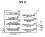
- 4WD controller 8 functionally includes generator control section 8A, relay control section 8B, motor control section 8C, extra torque calculating section 8E, target torque controlling section 8F, extra torque converting section 8G, and a circuit switching control section 8H which constitutes a circuit switching controlling section (means).
- generator control section 8A relay control section 8B
- motor control section 8C extra torque calculating section 8E
- target torque controlling section 8F target torque controlling section 8F
- extra torque converting section 8G extra torque converting section
- circuit switching control section 8H which constitutes a circuit switching controlling section (means).
- the difference point from the first embodiment will only be described below.
- the flowcharts of Figs. 5, 6, 7, and 8 are applicable to the sixth embodiment.
- a process of circuit switching control section 8H will be described with reference to a flowchart of Fig. 19.
- Circuit switching control section 8h executes the process as shown in Fig. 19 on the basis of the inputted respective signals for each predetermined period of time.
- circuit switching control section 42 determines whether the mode selected by the driver is " auto mode " or not. If section 8H determines " auto mode " (Yes) at a step S400, the routine goes to a step S410. If section 8H determines " LSD mode " (No), the routine goes to a step S430.
- a default value of the circuit switching operation section 42 is, for example, set to, for example, LSD mode.
- circuit switching control section 8H determines ' whether the vehicular running state is in a turning state depending upon whether a steering angle quantity (angular displacement) based on the signal of the steering angle sensor, a magnitude of a lateral G developed on the vehicle detected by a lateral G sensor, and a magnitude of a difference in speed between left and right road wheels is equal to or larger than a predetermined value. If section 8H determines that the vehicular running state is in the turning state, the routine goes to a step S420. If the vehicular running state is not in the turning state (No) at step S410, the routine goes to a step S430.
- circuit switching control section 8H determines whether, for example, the vehicular traveling state is under a tendency of oversteering on the basis of a direction (plus direction or minus direction) of deviation between a target yaw rate determined from, for example, a vehicular body velocity and the steering angle and actual yaw rate actually detected. If section 8H determines that the vehicular driving state is under the oversteering tendency (Yes), the routine goes to step S430. If section 8H determines that the vehicular driving state is not under the oversteering tendency (No) at step S420, the routine goes to a step S440. At step S430, section 8H outputs the parallel connection command to switch box 41 to constitute the parallel circuit described above.
- step S440 section 8H outputs the serial connection command to switch box 41 to constitute the serial circuit.
- step S410 constitutes a turning determining section (means)
- step S420 constitutes an oversteering determining (means).
- the process of the engine controller 18 is the same as described in the first embodiment.
- each clutch 12RL and 12RR is connected so that left and right rear road wheels 3L and 3R are connected to drive axles of drive motors 4RL and 4RR, respectively.
- generator 7 generates the electric power by means of generator load torque Th in accordance with the acceleration slip quantity so as to be transferred to the four-drive wheel state.
- the drive torque transmitted to front left and right road wheels 1L and 1R is adjusted to approach to the road surface reaction force limit torque and, then, the vehicle drive state is transferred to the two wheel drive state. Consequently, the acceleration slip on front left and right road wheels 1L and 1R which are main drive wheels is suppressed.
- the armature current is supplied to left and right drive motors 4RL and 4RR from generator 7 which is a common power supply.
- the serial circuit is selected. It is noted that, during the vehicular turning, since the motor speed at an inner wheel side (namely, the road wheel speeds at the inner road wheels) are relatively slowed, the induced voltage becomes lowered than the inner wheels as compared with the outer wheels.
- the parallel circuit In a case where the parallel circuit is adopted, a motor torque at the inner road wheel side becomes large so that it becomes difficult to turn the vehicle.
- the serial circuit by selecting the serial circuit as in the sixth embodiment, the armature current values supplied to left and right road wheel drive motors 4RL and 4RR take always the same value even if a difference in the induced voltages of left and right drive motors 4RL and 4RR occurs. Hence, the difficulty in turning the vehicle as in the case of the parallel circuit can be avoided.
- the parallel circuit is selected so that the difficulty in the vehicular turning causes a moment suppressing the oversteering tendency to be acted upon the vehicle.
- a vehicular stability can be improved.
- predetermined turning performance and turning stability can be improved by a simple switching selectively the appropriate electrical connection.
- the other advantages and alternatives are the same as those described in the first embodiment.
- the present invention is applicable to a two-wheel-drive electrical vehicle and a motor driven vehicle of a type in which the motors are installed independently on the left and right road wheels.
- a seventh preferred embodiment of the drive controlling apparatus will be described with reference to the drawings.
- the same reference numerals as those described in each of the first through sixth embodiments designate like elements in the seventh embodiment.
- a basic structure of the seventh embodiment is generally the same as in the first (or sixth) embodiment.
- the difference point from the sixth embodiment lies in the process of circuit switching controlling section 8H.
- the modes of circuit switching operation section 42 in the seventh embodiment are three kinds of " auto mode ", " parallel mode ", and " serial mode ".
- Circuit switching control section 8H in the seventh embodiment carries out the process shown in a flowchart of Fig. 20 on the basis of each inputted signal for each predetermined sampling period of time.
- circuit switching control section 8H determines whether the mode selected by the driver is " auto mode " at a step S800. If section 8H determines that the mode is selected to "auto mode " (Yes) at step S800, the routine goes to a step S810. If section 8H determines that the mode is selected not to the auto mode (No), the routine goes to a step S820. At step S820, section 8H determines if only one of the left and right motor driven road wheels is under the acceleration slip. If section 8H determines that only one of the left and right motor driven road wheels is under the acceleration slip (Yes), the routine goes to a step S830.
- section 8H determines that only one of the left and right motor driven road wheels is not under the acceleration slip (No) at step S840.
- the determination of whether only one of the left and right motor driven road wheels is under the acceleration slip is carried out as follows. That is to say, for example, a turning radius is determined from the detected vehicular body velocity, the steering angular displacement, and the lateral G and an actual road wheel velocity of the one of the left and right road wheels is larger or not than each of reference road wheel velocities of the left and right road wheels calculated on the basis of the turning radius may detect the acceleration slip on one of the left and right road wheels.
- Step S810 constitutes an acceleration slip detecting section (means).
- section 8H determines whether the mode selected by the driver is " parallel mode ". If " parallel mode " is selected, the routine goes to a step S830. If section 8H determines that " serial mode " is selected (No), the routine goes to a step S840. At step S830, section 8H outputs the parallel connection command to switch box 41 and the routine is returned to step S800. If section 8H determines that the mode is not selected to the parallel mode, the routine goes to step S840. At step S840, section 8H outputs the serial connection command to switch box 41 and the process is ended (the routine is returned to step S800). It is noted that, as the process of circuit switching control section 8H, the process shown in Fig. 20 may be used during the straight run. During the turning, the process shown in Fig. 19 described in the sixth embodiment may be used.
- the serial circuit is selected. Consequently, armature current flowing through both of left and right road wheels 4RL and 4RR becomes mutually the same.
- the drive torques of left and right drive motors become mutually the same.
- driving forces developed on the left and right road wheels driven by respectively corresponding drive motors become mutually the same. Consequently, the stability driving the vehicular straight run is improved.
- the circuit is selected to the parallel circuit so that a difference limit function is activated. Then, the drive torque is applied to one of the left and right road wheels which is not in the acceleration slip state without failure so that the acceleration performance can be improved.
- the other structure, action, and advantages of the seventh embodiment are the same as those described in the first and sixth embodiments.
- serial circuit purpose controlling section of motor controlling section 8C may be constituted by operation determining section 50, left road wheel drive torque calculating section 61, right road wheel torque calculating section 62, deviation calculating section 53, polarity inverting section 54, rear left road wheel controlling section 55, and rear right road wheel controlling section 56, as shown in Fig. 10.
- right road wheel drive torque calculating section 61 calculates the drive torque of the rear right road wheel 3R on the basis of the output signal of the torque sensor installed on right drive motor 4RR and outputs the drive torque calculated to operational amplifier 53A.
- Left drive torque calculating section 62 calculates the drive torque of rear left road wheel 3L on the basis of the output signal of torque sensor disposed on left drive motor 4RL and outputs the calculated rear left road wheel to operational amplifier 53A.
- Operational amplifier 53A outputs the deviation with the plus value when the right road wheel drive torque is larger than the left road wheel drive torque and outputs the deviation with the minus value when the left road wheel drive torque is larger than the right road wheel torque.
- the other structure of motor controlling section 8C is the same as described in motor controlling section 8C in the second embodiment.
- the value in accordance with the deviation in the developed driving forces between the left and right road wheels is calculated from a torque difference between the left and right road wheels and the field current values of left and right drive motors 4RL and 4RR are respectively corrected so as to reduce the deviation therein.
Landscapes
- Engineering & Computer Science (AREA)
- Mechanical Engineering (AREA)
- Transportation (AREA)
- Power Engineering (AREA)
- Life Sciences & Earth Sciences (AREA)
- Combustion & Propulsion (AREA)
- Sustainable Energy (AREA)
- Chemical & Material Sciences (AREA)
- Sustainable Development (AREA)
- Architecture (AREA)
- Forests & Forestry (AREA)
- Civil Engineering (AREA)
- Structural Engineering (AREA)
- Electric Propulsion And Braking For Vehicles (AREA)
- Hybrid Electric Vehicles (AREA)
- Arrangement And Driving Of Transmission Devices (AREA)
Applications Claiming Priority (4)
| Application Number | Priority Date | Filing Date | Title |
|---|---|---|---|
| JP2003105999 | 2003-04-10 | ||
| JP2003105999A JP2004312944A (ja) | 2003-04-10 | 2003-04-10 | 車両の駆動制御装置 |
| JP2003113278 | 2003-04-17 | ||
| JP2003113278A JP3912315B2 (ja) | 2003-04-17 | 2003-04-17 | 車両の駆動制御装置 |
Publications (2)
| Publication Number | Publication Date |
|---|---|
| EP1466775A2 true EP1466775A2 (de) | 2004-10-13 |
| EP1466775A3 EP1466775A3 (de) | 2010-09-15 |
Family
ID=32871253
Family Applications (1)
| Application Number | Title | Priority Date | Filing Date |
|---|---|---|---|
| EP04252135A Withdrawn EP1466775A3 (de) | 2003-04-10 | 2004-04-08 | Antriebskontrollapparat und Methode für Kraftfahrzeug |
Country Status (4)
| Country | Link |
|---|---|
| US (1) | US7356391B2 (de) |
| EP (1) | EP1466775A3 (de) |
| KR (1) | KR100571942B1 (de) |
| CN (1) | CN1308163C (de) |
Cited By (4)
| Publication number | Priority date | Publication date | Assignee | Title |
|---|---|---|---|---|
| EP1520761A2 (de) | 2003-10-02 | 2005-04-06 | Toyoda Koki Kabushiki Kaisha | Integrierte Steuervorrichtung für Kraftfahrzeug |
| EP2008900A1 (de) * | 2007-06-28 | 2008-12-31 | Honda Motor Co., Ltd. | Antriebssteuervorrichtung für Fahrzeuge |
| EP2014531A3 (de) * | 2007-06-21 | 2009-06-03 | Honda Motor Co., Ltd | Fahrzeugantriebssteuerungssystem |
| GB2550555A (en) * | 2016-05-16 | 2017-11-29 | Jaguar Land Rover Ltd | System for a drive line of a vehicle |
Families Citing this family (48)
| Publication number | Priority date | Publication date | Assignee | Title |
|---|---|---|---|---|
| JP3879650B2 (ja) * | 2002-10-15 | 2007-02-14 | 日産自動車株式会社 | 車両の制御装置 |
| KR100729251B1 (ko) * | 2003-04-04 | 2007-06-15 | 도요다 지도샤 가부시끼가이샤 | 시프트 제어 시스템, 시프트 제어 방법 및 시프트 스위칭디바이스 |
| US7292009B2 (en) * | 2003-09-17 | 2007-11-06 | Honda Motor Co., Ltd. | Hybrid type working machine |
| JP3912399B2 (ja) * | 2003-09-29 | 2007-05-09 | 日産自動車株式会社 | 車両用駆動装置 |
| JP4727410B2 (ja) * | 2005-12-16 | 2011-07-20 | トヨタ自動車株式会社 | ステアリング制御装置および電動車両 |
| JP2007252153A (ja) * | 2006-03-20 | 2007-09-27 | Hitachi Ltd | 自動車の制御装置及び自動車 |
| ITMI20061157A1 (it) * | 2006-06-15 | 2007-12-16 | Piaggio & C Spa | Metodo di gestione delle modalita' di funzionamento di un gruppo motopropulsore ibrido impiegante lo stesso |
| KR100836292B1 (ko) | 2006-12-08 | 2008-06-11 | 현대자동차주식회사 | 사륜구동 하이브리드 차량의 구동력 제어방법 |
| JP4415994B2 (ja) * | 2007-02-01 | 2010-02-17 | トヨタ自動車株式会社 | ヨー角速度推定装置 |
| US20110011656A1 (en) * | 2007-03-20 | 2011-01-20 | Peder Ulrik Poulsen | Hybrid vehicle system with indirect drive |
| US20080257620A1 (en) * | 2007-03-20 | 2008-10-23 | Peder Ulrik Poulsen | Hybrid Vehicle Drive System |
| DE102009000044A1 (de) * | 2009-01-07 | 2010-07-08 | Robert Bosch Gmbh | Verfahren und Vorrichtung zum Betreiben eines Fahrzeuges, insbesondere eines Hybridfahrzeuges |
| US8138704B2 (en) * | 2009-05-22 | 2012-03-20 | GM Global Technology Operations LLC | Methods and systems for detecting current sensor error |
| US20100305819A1 (en) * | 2009-05-29 | 2010-12-02 | Nokia Corporation | Method, apparatus and computer program product for determining vehicle engine revolutions per minute and gear position information using location information |
| DE102010012153A1 (de) | 2010-03-20 | 2011-09-22 | Audi Ag | Fahrzeug mit zumindest zwei Einzelradantriebseinheit |
| CN102195538A (zh) * | 2010-03-26 | 2011-09-21 | 朱炎炎 | 电动车车轮驱动电机供电控制方法 |
| FR2958592B1 (fr) * | 2010-04-12 | 2012-06-01 | Renault Sa | Procede de fonctionnement d'un systeme de transmission d'un vehicule automobile |
| US8433465B2 (en) * | 2010-06-08 | 2013-04-30 | Ford Global Technologies, Llc | Transitioning between series-drive and parallel-drive in a hybrid-electric vehicle powertrain |
| US8708074B1 (en) | 2010-06-15 | 2014-04-29 | Hydro-Gear Limited Partnership | Selectable four-wheel drive system |
| CN102294999A (zh) * | 2010-06-23 | 2011-12-28 | 北汽福田汽车股份有限公司 | 用于四轮驱动汽车的驱动模式控制系统 |
| CN102463986A (zh) * | 2010-11-08 | 2012-05-23 | 申水文 | 四轮驱动混合动力车辆前后轮力矩分配控制方法 |
| US8744710B2 (en) * | 2011-03-30 | 2014-06-03 | Nissin Kogyo Co., Ltd. | Control device for controlling drive force that operates on vehicle |
| WO2013046313A1 (ja) | 2011-09-27 | 2013-04-04 | トヨタ自動車株式会社 | 車両および車両の制御方法 |
| US9162670B2 (en) * | 2011-09-27 | 2015-10-20 | Toyota Jidosha Kabushiki Kaisha | Vehicle and method of controlling vehicle |
| JP5836181B2 (ja) | 2012-03-30 | 2015-12-24 | 本田技研工業株式会社 | 車両用駆動装置及び車両用駆動装置の制御方法 |
| JP5947086B2 (ja) * | 2012-04-02 | 2016-07-06 | ダイムラー・アクチェンゲゼルシャフトDaimler AG | 車両の変速制御装置 |
| CN102815230A (zh) * | 2012-08-23 | 2012-12-12 | 陈国华 | 一种电动汽车 |
| CN102975631B (zh) * | 2012-11-28 | 2017-10-10 | 沈阳工业大学 | 四轮全驱电动汽车轴饱和补偿姿态控制系统及控制方法 |
| KR101399263B1 (ko) * | 2012-12-28 | 2014-05-27 | 현대위아 주식회사 | 하이브리드 차량의 후륜 모터 구동 시스템 |
| WO2014160728A2 (en) | 2013-03-25 | 2014-10-02 | Polaris Industries Inc. | Tracked all-terrain vehicle |
| FR3004231B1 (fr) * | 2013-04-05 | 2015-04-03 | Renault Sa | Procede de controle de l'etat d'une chaine cinematique d'un groupe motopropulseur de vehicule electrique hybride ou thermique |
| CN103192727B (zh) * | 2013-04-24 | 2015-11-18 | 柯德华 | 多电机前后驱动电动车 |
| CN103939599B (zh) * | 2014-04-29 | 2016-10-05 | 长城汽车股份有限公司 | 一种自动变速器换挡控制方法、装置及系统 |
| CN105480114B (zh) * | 2014-09-15 | 2017-09-08 | 常州爱尔威智能科技有限公司 | 自平衡双轮电动车转向控制方法及自平衡双轮电动车 |
| CN104627026B (zh) * | 2014-12-08 | 2016-10-12 | 无锡富迪电动车有限公司 | 一种电动车适时智能驱动联动系统及其控制方法 |
| US9963155B2 (en) | 2015-05-29 | 2018-05-08 | Clearpath Robotics, Inc. | Method, system and apparatus for path control in unmanned vehicles |
| KR101752980B1 (ko) | 2015-12-24 | 2017-07-03 | 현대다이모스(주) | 친환경 차량의 후륜 구동장치 |
| US10730551B2 (en) * | 2016-08-09 | 2020-08-04 | Polaris Industries Inc. | Tracked all-terrain vehicle |
| CN106531235B (zh) * | 2016-12-29 | 2017-09-12 | 中科瑞华原子能源技术有限公司 | 一种原位运动的紧凑型反应性控制机构 |
| US10585440B1 (en) | 2017-01-23 | 2020-03-10 | Clearpath Robotics Inc. | Systems and methods for using human-operated material-transport vehicles with fleet-management systems |
| US11097736B2 (en) | 2017-02-28 | 2021-08-24 | Clearpath Robotics Inc. | Systems and methods for traction detection and control in a self-driving vehicle |
| US11390277B2 (en) | 2018-11-30 | 2022-07-19 | Clearpath Robotics Inc. | Systems and methods for self-driving vehicle collision prevention |
| DE102019100324A1 (de) * | 2019-01-08 | 2020-07-09 | Bayerische Motoren Werke Aktiengesellschaft | Vorrichtung zur Kalibrierung zweier auf einer Achse angeordneter Elektromotoren in zweiachsigen Kraftfahrzeugen |
| US11649147B2 (en) | 2019-09-20 | 2023-05-16 | Clearpath Robotics Inc. | Autonomous material transport vehicles, and systems and methods of operating thereof |
| US12122367B2 (en) | 2020-09-10 | 2024-10-22 | Rockwell Automation Technologies, Inc. | Systems and methods for operating one or more self-driving vehicles |
| JP2022187356A (ja) * | 2021-06-07 | 2022-12-19 | トヨタ自動車株式会社 | 車両制御装置、車両制御プログラム及び車両制御システム |
| US11607952B1 (en) * | 2022-05-04 | 2023-03-21 | Dimaag-Ai, Inc. | Methods and systems for controlling differential wheel speeds of multi- independent-wheel drive vehicles |
| US12498732B2 (en) | 2024-01-17 | 2025-12-16 | Rockwell Automation Technologies, Inc. | Systems and methods for characterizing a vehicle motion of an autonomous mobile robot |
Citations (5)
| Publication number | Priority date | Publication date | Assignee | Title |
|---|---|---|---|---|
| GB2323940A (en) * | 1994-06-27 | 1998-10-07 | Fuji Heavy Ind Ltd | Controlling torque distribution between the rear wheels of a vehicle |
| JP2000318473A (ja) | 1999-05-12 | 2000-11-21 | Honda Motor Co Ltd | 前後輪駆動車両 |
| JP2003105999A (ja) | 2001-10-01 | 2003-04-09 | Hitachi Building Systems Co Ltd | 駐車装置 |
| JP2003113278A (ja) | 2001-07-25 | 2003-04-18 | Sumitomo Chem Co Ltd | 熱可塑性エラストマー組成物、該組成物からなるパウダー及び該組成物からなるパウダーを粉末成形してなる成形体 |
| GB2383567A (en) * | 2001-12-28 | 2003-07-02 | Visteon Global Tech Inc | Vehicle stability control |
Family Cites Families (22)
| Publication number | Priority date | Publication date | Assignee | Title |
|---|---|---|---|---|
| US4042055A (en) * | 1975-12-18 | 1977-08-16 | Ward Eugene T | Battery powered vehicle and drive system |
| US4351405A (en) * | 1978-10-12 | 1982-09-28 | Hybricon Inc. | Hybrid car with electric and heat engine |
| DE3206492C2 (de) * | 1982-02-24 | 1985-03-28 | Rheinisch-Westfälisches Elektrizitätswerk AG, 4300 Essen | Elektromotorisch angetriebenes Straßenfahrzeug |
| US4500818A (en) * | 1983-12-22 | 1985-02-19 | General Electric Company | Dual motor proportioning control |
| JPH0623121Y2 (ja) * | 1986-08-05 | 1994-06-15 | 昌煕 金 | 自動車の電気駆動推進装置 |
| FR2769552B1 (fr) * | 1997-10-10 | 2001-03-23 | Martine Losego | Systeme de motorisation d'un chariot de transport d'objets |
| DE4133013C2 (de) * | 1991-10-04 | 1995-11-30 | Mannesmann Ag | Nicht-spurgebundenes Fahrzeug mit elektrodynamischem Wandler |
| DE4133622A1 (de) * | 1991-10-10 | 1993-04-22 | Mannesmann Ag | Drehzahlerfassung bei einer antriebsanordnung fuer ein kraftfahrzeug |
| CN1080251A (zh) * | 1992-06-18 | 1994-01-05 | 张信 | 单独驱动的双轮电汽车 |
| JPH08133086A (ja) | 1994-11-07 | 1996-05-28 | Takuma Seiko:Kk | モータ駆動式走行車 |
| JPH11262195A (ja) * | 1998-03-12 | 1999-09-24 | Honda Motor Co Ltd | 車両用電源装置 |
| EP1759915A3 (de) * | 1998-07-21 | 2007-03-14 | TOKYO R&D CO., LTD. | Hybridfahrzeug und Verfahren zur Fahrzeugfahrtregelung |
| JP2000142157A (ja) | 1998-11-16 | 2000-05-23 | Honda Motor Co Ltd | 電動駆動力アシスト車両 |
| KR100342017B1 (ko) * | 1999-07-16 | 2002-06-27 | 전성즙 | 하이브리드 자동차의 동력 전달 장치 |
| US6611116B2 (en) * | 2000-05-10 | 2003-08-26 | Curtis Instruments, Inc. | Anti-spin control for a separately excited motor drive system |
| JP4178755B2 (ja) * | 2001-01-16 | 2008-11-12 | 三菱電機株式会社 | 自動車のバッテリー用電力回路 |
| JP4193496B2 (ja) * | 2001-04-20 | 2008-12-10 | セイコーエプソン株式会社 | 制御対象の駆動制御装置 |
| JP3551178B2 (ja) | 2001-09-10 | 2004-08-04 | 日産自動車株式会社 | 車両のクラッチ制御装置 |
| JP3541831B2 (ja) | 2001-10-26 | 2004-07-14 | 日産自動車株式会社 | 車両の駆動力制御装置 |
| US20030090225A1 (en) * | 2001-11-14 | 2003-05-15 | Posma Bonne W. | Controller for two DC traction motors |
| JP3536838B2 (ja) | 2002-01-11 | 2004-06-14 | 日産自動車株式会社 | 車両の駆動力制御装置 |
| JP3575479B2 (ja) | 2002-03-08 | 2004-10-13 | 日産自動車株式会社 | 車両の駆動力制御装置 |
-
2004
- 2004-04-08 US US10/820,059 patent/US7356391B2/en not_active Expired - Fee Related
- 2004-04-08 EP EP04252135A patent/EP1466775A3/de not_active Withdrawn
- 2004-04-09 CN CNB2004100328474A patent/CN1308163C/zh not_active Expired - Fee Related
- 2004-04-09 KR KR1020040024278A patent/KR100571942B1/ko not_active Expired - Fee Related
Patent Citations (5)
| Publication number | Priority date | Publication date | Assignee | Title |
|---|---|---|---|---|
| GB2323940A (en) * | 1994-06-27 | 1998-10-07 | Fuji Heavy Ind Ltd | Controlling torque distribution between the rear wheels of a vehicle |
| JP2000318473A (ja) | 1999-05-12 | 2000-11-21 | Honda Motor Co Ltd | 前後輪駆動車両 |
| JP2003113278A (ja) | 2001-07-25 | 2003-04-18 | Sumitomo Chem Co Ltd | 熱可塑性エラストマー組成物、該組成物からなるパウダー及び該組成物からなるパウダーを粉末成形してなる成形体 |
| JP2003105999A (ja) | 2001-10-01 | 2003-04-09 | Hitachi Building Systems Co Ltd | 駐車装置 |
| GB2383567A (en) * | 2001-12-28 | 2003-07-02 | Visteon Global Tech Inc | Vehicle stability control |
Cited By (8)
| Publication number | Priority date | Publication date | Assignee | Title |
|---|---|---|---|---|
| EP1520761A2 (de) | 2003-10-02 | 2005-04-06 | Toyoda Koki Kabushiki Kaisha | Integrierte Steuervorrichtung für Kraftfahrzeug |
| EP2014531A3 (de) * | 2007-06-21 | 2009-06-03 | Honda Motor Co., Ltd | Fahrzeugantriebssteuerungssystem |
| CN101327793B (zh) * | 2007-06-21 | 2012-05-16 | 本田技研工业株式会社 | 车辆用驱动控制装置 |
| EP2008900A1 (de) * | 2007-06-28 | 2008-12-31 | Honda Motor Co., Ltd. | Antriebssteuervorrichtung für Fahrzeuge |
| CN101332815B (zh) * | 2007-06-28 | 2012-02-01 | 本田技研工业株式会社 | 车辆用驱动控制装置 |
| US8209099B2 (en) | 2007-06-28 | 2012-06-26 | Honda Motor Co., Ltd. | Drive control apparatus for vehicle |
| GB2550555A (en) * | 2016-05-16 | 2017-11-29 | Jaguar Land Rover Ltd | System for a drive line of a vehicle |
| GB2550555B (en) * | 2016-05-16 | 2020-09-09 | Jaguar Land Rover Ltd | System for a drive line of a vehicle |
Also Published As
| Publication number | Publication date |
|---|---|
| EP1466775A3 (de) | 2010-09-15 |
| US20040204803A1 (en) | 2004-10-14 |
| US7356391B2 (en) | 2008-04-08 |
| KR100571942B1 (ko) | 2006-04-18 |
| CN1308163C (zh) | 2007-04-04 |
| KR20040089505A (ko) | 2004-10-21 |
| CN1535861A (zh) | 2004-10-13 |
Similar Documents
| Publication | Publication Date | Title |
|---|---|---|
| EP1466775A2 (de) | Antriebskontrollapparat und Methode für Kraftfahrzeug | |
| CN100376438C (zh) | 汽车及其控制方法 | |
| CN100368224C (zh) | 车辆驱动力控制装置 | |
| JP4135682B2 (ja) | 車両の駆動力制御装置 | |
| EP1966019B1 (de) | Hybridfahrzeug und steuerungsverfahren dafür | |
| EP1547841B1 (de) | Vierrad- Antriebssystem | |
| US6575870B2 (en) | Driving force control system for front-and-rear wheel drive vehicles | |
| EP1535786B1 (de) | Antriebsschlupfregelsystem in einem Hybridfahrzeug mit Allradantrieb. | |
| JP2009278770A (ja) | 車両およびその制御方法 | |
| EP1533171B1 (de) | Antriebskraftsteuerungsvorrichtung für ein Kraftfahrzeug | |
| EP1604854B1 (de) | Antriebskraftsteuerung für Automobile | |
| US7533743B2 (en) | Control device for hybrid vehicle | |
| JP3891166B2 (ja) | 車両の駆動力制御装置 | |
| US11208089B2 (en) | Drive-force control apparatus for vehicle | |
| JP2004104843A (ja) | 車両の駆動力制御装置 | |
| JPH11125129A (ja) | 車 輌 | |
| JP3912315B2 (ja) | 車両の駆動制御装置 | |
| JP2004312944A (ja) | 車両の駆動制御装置 | |
| JP2009214805A (ja) | 車両の駆動力制御装置 | |
| JP3933149B2 (ja) | 車両の駆動力制御装置 | |
| JP2025064714A (ja) | 四輪駆動車両の制御装置 |
Legal Events
| Date | Code | Title | Description |
|---|---|---|---|
| PUAI | Public reference made under article 153(3) epc to a published international application that has entered the european phase |
Free format text: ORIGINAL CODE: 0009012 |
|
| 17P | Request for examination filed |
Effective date: 20040423 |
|
| AK | Designated contracting states |
Kind code of ref document: A2 Designated state(s): AT BE BG CH CY CZ DE DK EE ES FI FR GB GR HU IE IT LI LU MC NL PL PT RO SE SI SK TR |
|
| AX | Request for extension of the european patent |
Extension state: AL HR LT LV MK |
|
| PUAL | Search report despatched |
Free format text: ORIGINAL CODE: 0009013 |
|
| AK | Designated contracting states |
Kind code of ref document: A3 Designated state(s): AT BE BG CH CY CZ DE DK EE ES FI FR GB GR HU IE IT LI LU MC NL PL PT RO SE SI SK TR |
|
| AX | Request for extension of the european patent |
Extension state: AL HR LT LV MK |
|
| AKX | Designation fees paid |
Designated state(s): DE FR GB |
|
| 17Q | First examination report despatched |
Effective date: 20151005 |
|
| STAA | Information on the status of an ep patent application or granted ep patent |
Free format text: STATUS: THE APPLICATION IS DEEMED TO BE WITHDRAWN |
|
| 18D | Application deemed to be withdrawn |
Effective date: 20160216 |