EP1460025A1 - Hebezeug mit zwei Lastseilen - Google Patents
Hebezeug mit zwei Lastseilen Download PDFInfo
- Publication number
- EP1460025A1 EP1460025A1 EP04006788A EP04006788A EP1460025A1 EP 1460025 A1 EP1460025 A1 EP 1460025A1 EP 04006788 A EP04006788 A EP 04006788A EP 04006788 A EP04006788 A EP 04006788A EP 1460025 A1 EP1460025 A1 EP 1460025A1
- Authority
- EP
- European Patent Office
- Prior art keywords
- load
- housing
- rope
- cable
- drum
- Prior art date
- Legal status (The legal status is an assumption and is not a legal conclusion. Google has not performed a legal analysis and makes no representation as to the accuracy of the status listed.)
- Granted
Links
Images



Classifications
-
- B—PERFORMING OPERATIONS; TRANSPORTING
- B66—HOISTING; LIFTING; HAULING
- B66C—CRANES; LOAD-ENGAGING ELEMENTS OR DEVICES FOR CRANES, CAPSTANS, WINCHES, OR TACKLES
- B66C13/00—Other constructional features or details
- B66C13/12—Arrangements of means for transmitting pneumatic, hydraulic, or electric power to movable parts of devices
- B66C13/14—Arrangements of means for transmitting pneumatic, hydraulic, or electric power to movable parts of devices to load-engaging elements or motors associated therewith
-
- B—PERFORMING OPERATIONS; TRANSPORTING
- B66—HOISTING; LIFTING; HAULING
- B66D—CAPSTANS; WINCHES; TACKLES, e.g. PULLEY BLOCKS; HOISTS
- B66D1/00—Rope, cable, or chain winding mechanisms; Capstans
- B66D1/28—Other constructional details
- B66D1/30—Rope, cable, or chain drums or barrels
-
- B—PERFORMING OPERATIONS; TRANSPORTING
- B66—HOISTING; LIFTING; HAULING
- B66D—CAPSTANS; WINCHES; TACKLES, e.g. PULLEY BLOCKS; HOISTS
- B66D3/00—Portable or mobile lifting or hauling appliances
- B66D3/18—Power-operated hoists
Definitions
- the invention relates to a hoist in the manner of a cable balancer with a housing which can be suspended and a threaded spindle arranged in the housing, a piston which is longitudinally displaceable by fluid pressure in the housing and a spindle nut which is in direct operative connection with the threaded spindle and a cable drum for a cable groove which is guided in a cable groove on the drum circumference Load rope that emerges from the housing at a fixed drain point, the rope drum being rotatably connected to the piston.
- a rope is rolled up or unwound from a rope drum.
- the rope is guided around the circumference like a single-start screw in a groove.
- the drum is usually driven by a pneumatic cylinder via a nut, eg a ball screw spindle.
- the linear movement of the pneumatic cylinder is converted into a rotary movement by the ball screw spindle.
- One end of the rope is attached to the circumference of the drum and the other free end of the rope leads down out of the rope balancer housing and carries the load handler.
- the load handler When the rope is rolled up, the free end of the rope is pulled up, lifting the load handler.
- the load handler When the rope is unrolled, the free end of the rope is lowered and the load handler is lowered.
- the piston which is pressurized with fluid pressure, counteracts the tendency of the load to unwind the rope and thus compensates for load differences of the loaded or unloaded load rope.
- Such rotary couplings have a higher friction resistance than the rope twist resistance. It is not possible to absorb load moments through the single rope, which makes it difficult to use with load suspension devices and workpieces with a focus away from the load suspension point. An increased rope bending stiffness results when thicker ropes are used, which results in poorer running behavior or winding behavior, so this measure does not provide a remedy. A single rope does not offer safety when the rope breaks.
- a balancer is known from publication WO 00/699771, the load-carrying means of which is connected to a cuff which the operator couples to his forearm.
- the load-carrying means of which is connected to a cuff which the operator couples to his forearm.
- ratiolift L90 from EFS-GmbH, Nordheim, DE is known, which is operated with two load cables, which are held by a pulley.
- Two ropes are run over four ball-bearing pulleys.
- Two rope pulleys with the rope pulley axis are fixed in the rope balancer housing and two rope pulleys are moved away from the fixed pulleys by means of a traversing slide by means of a pneumatic cylinder drive, or pushed together again.
- By pushing apart the rope wrap between the pairs of rollers is extended. Pushing the rope together shortens the rope pairs.
- One rope end of each of the two double ropes is attached to the rope balancer housing, and the two free rope ends lead out of the rope balancer housing downwards and carry the traverse on the load suspension device. By extending the rope wrap, the free ends of the rope are pulled up, thereby lifting the traverse with the load handler.
- the free rope ends are lowered and the crossbar with the load handler is lowered.
- the device builds relatively long. This means that it takes up a lot of space for the arrangement of the rope pulleys, the travel path of the travel carriage and the pneumatic cylinder.
- the travels of the cable balancer device of the system usually attached to the crane rail system or a rail swivel bracket are considerably restricted.
- the device is quite heavy in relation to the usable load. This means that it is necessary to reinforce the crane rail system or the swivel boom. Due to the addition of the weights of the cable balancer and the crane-rail system or the swivel boom, the overall weight is high.
- the invention is based on the problem of proposing an improved balancer with which problems of previous designs, in particular cumbersome handling of light workpieces, Damage to torsion and rope breakage can be avoided.
- two rope grooves preferably in parallel, are arranged on the drum circumference, for two load ropes guided approximately in parallel, the exit points leading out of the housing or being led out at two spaced-apart run-out points.
- the ropes do not necessarily have to be absolutely parallel to the load, but with the greatest possible distance. The higher the distance, the greater the common twist resistance when handling loads. This twisting is particularly troublesome in the case of work that can be repeated quickly, in which, for example, small but tiring heavy loads have to be transported over short distances at a high frequency.
- the ropes are guided in parallel on the circumference of the rope drum either in a type of double-start screw or worm or two track grooves arranged next to one another and wound up and unwound.
- the cable reel is driven by means of hydraulic or pneumatic cylinders via a preferably a smooth-running ball roller spindle with a spindle nut.
- Other spindle nut systems can still be used but are more difficult to move.
- the linear movement of the pneumatic cylinder is converted into a rotary movement of the cable drum via the spindle nut / ball screw.
- the spindle nut is non-rotatably connected to the rope drum, in other designs the spindle nut is indirectly coupled to the housing via a torque support and is operatively connected to the rope drum via the threaded spindle.
- the use of different designs depends on the one hand on the desired vertical range of manufacture with more or less mechanical Processing or the application of welding technologies on the other hand together with the desired smoothness or the weight or lifting height of the load to be transported and thus the thickness of the ropes and the drum sizes or the permissible friction loads. The easier the ropes are to run or the smaller the rope diameter, the more precise the mechanical production must be.
- each of the two ropes is attached to the circumference of the moving spool or drum, and the other ends of the ropes run downwards at a distance from the rope balancer housing and are connected with a crossbar, or are attached directly to the load handler.
- the invention allows the two ropes to be used in combination with endless rotary couplings for the air passage of the control air of the balancer drive and for the control air of the load handling devices because of the common twisting resistance, since the air hoses are no longer or hardly twisted.
- the device according to the invention has the same advantages as a double rope balancer based on the block and tackle principle and offers no synchronization problems for the uniform rope stroke compared to a theoretically possible, but much more expensive, solution with two single-rope balancers arranged in parallel. The safety against a load drop is increased and the risk of injury to the operator or failure of the device due to rope damage is dramatically reduced.
- a double-rope balancer 3 according to FIG. 1 is positively attached to a ceiling rail system 1 by means of suspension 2, in which it can be moved linearly longitudinally or (not shown) transversely.
- a housing 4 is closed on both sides by covers 5 and 6.
- the covers take up a spindle 8, fastened in a rotationally fixed manner in cover 5 with screw 9, which is extended with a guide tube 12 and, on the other hand, is fixed in a rotationally fixed manner in cover 6 with screw 9 '.
- Cover 6 and piston 10 of a pneumatic cylinder close the pressure chamber 11 in the housing, which can be acted upon by a pressure source, not shown, with fluid pressure.
- the piston 10 is connected to a bearing by means of screws 17, wherein it is arranged so as to be longitudinally displaceable on the guide tube 12 by means of slide or roller bearings 15 and is rotatably coupled to a cable drum 13 via roller bearings 16.
- the cable drum 13, on the other hand, is firmly connected with screws 14 to a ball screw nut 7, which can roll in a thread 18 of the threaded spindle 8.
- the jacket of the drum 13 carries two helical cable grooves R1 and R2 for two load cables L1 and L2, which are attached to the drum with one end.
- the load ropes L1 and L2 leave the housing 4 at fixed run-off points A1 and A2, which here are at a distance of approximately 80-100 mm.
- the other ends L21 and L22 of the load cables are connected by a crossbar T and carry a rotary coupling K for the passage of compressed air with an airtight rotary seal D, under which a load suspension device can be arranged on attachment B.
- the air hoses for the control air and the load handler are labeled 19 and 20.
- the reference numbers for parts with the same function are repeated, but differ in the figure number added.
- FIG. 2 shows a similar drum 213 with cable grooves R1, R2, the rotation of which is represented by the rotary arrow, in a housing 204.
- the threaded spindle 208 with thread 218 is only fastened to cover 205 (e.g. B. with a weld seam 209) and does not reach through the piston 210 nor the pressure chamber 211 to the cover 206.
- FIG. 3 shows a drum 313 in housing 304, which is designed on the circumference and its attachment to piston 310 like the drum in FIG. 2.
- Drum 313 on the one hand and threaded spindle 308 with thread 318 on the other hand are connected to one another in a rotationally fixed manner, while the necessary spindle nut 307 is overhung on a tube 321 welded to cover 305 with weld seam 309.
- FIG. 4 and 5 show cable drums 413 and 513 which are rotatably mounted in the housing 404 and 504 by means of bearings 416 and 516, respectively.
- Two cable grooves R1 and R2 are arranged on the circumference of the drums approximately at a distance from the cable lead-throughs or cable outlet points A1 and A2, in which the ropes L1 and L2 can wind on top of each other or partly side by side.
- the pistons 410 and 510 are non-rotatably connected to the threaded spindle 408 (FIG. 4) and to the spindle nut 507 via a tube 521 (FIG. 5).
- the threaded spindle 408 has a torque support 419 or the tube has such a support 519, the support being able to move in a slot 420 or 520 of the housing 404 or 504 in the direction of displacement V when the piston is pressed by the pressure in the pressure chamber 411 or 511 is shifted in order to wind the cables L1 and L2 synchronously on or from the drum.
- the spindle nut 407 is connected in a rotationally fixed manner to the drum 413 as in FIGS. 1 and 2; 5, the spindle nut is held in a form-fitting and rotationally fixed manner by the tube 521 welded to piston 510 with weld seam 509.
Landscapes
- Engineering & Computer Science (AREA)
- Mechanical Engineering (AREA)
- Storage Of Web-Like Or Filamentary Materials (AREA)
- Jib Cranes (AREA)
- Ropes Or Cables (AREA)
- Transmission Devices (AREA)
- Carriers, Traveling Bodies, And Overhead Traveling Cranes (AREA)
- Storing, Repeated Paying-Out, And Re-Storing Of Elongated Articles (AREA)
- Load-Engaging Elements For Cranes (AREA)
Abstract
Description
- Die Erfindung betrifft ein Hebezeug nach Art eines Seilbalancers mit einem aufhängbaren Gehäuse und einer im Gehäuse angeordneten Gewindespindel, einem durch Fluiddruck im Gehäuse längsverschiebbaren Kolben und einer Spindelmutter, die in direkter Wirkverbindung mit der Gewindespindel steht und einer Seiltrommel für ein am Trommelumfang in einer Seilrille geführtes Lastseil, das an einem festen Ablaufpunkt aus dem Gehäuse austritt, wobei die Seiltrommel drehbar mit dem Kolben verbunden ist.
- Ein derartiges gattungsgemäßes Hebezeug ist aus der Druckschrift US - A 5,553,832 bekannt. Diese Hebezeuge dienen dazu den Bediener in die Lage zu versetzen eine Last beinah schwerelos zu balancieren und ohne großen Kraftaufwand zu bewegen. Ähnliche Hebezeuge sind in den Druckschriften US-A 5,522,581, EP 1136423 A1, EP 1262 442 A2 und EP 0428 724 A1 offenbart.
- Dabei wird ein Seil von einer Seiltrommel aufgerollt oder abgerollt. Das Seil wird am Umfang nach Art einer eingängigen Schraube in einer Rille geführt. Die Trommel wird in der Regel mit einem Pneumatik-Zylinder über eine Mutter z.B. eine Kugelroll-Spindel angetrieben, Dabei wird die Linearbewegung des Pneumatikzylinders über die Kugelrollspindel in eine Drehbewegung umgesetzt. Ein Seilende ist am Umfang der Trommel befestigt und das andere freie Seilende führt aus dem Seilbalancergehäuse nach unten heraus und trägt das Lastaufnahmemittel. Durch das Aufrollen des Seiles wird das freie Seilende hochgezogen und dadurch das Lastaufnahmemittel angehoben. Durch das Abrollen des Seiles wird das freie Seilende abgelassen und dadurch das Lastaufnahmemittel abgesenkt. Der mit Fluiddruck beaufschlagte Kolben begegnet der Tendenz der Last, das Seil abzuwickeln und kompensiert so Lastdifferenzen des belasteten oder unbelasteten Lastseiles.
- In der Praxis tauchen bei der Handhabung der Geräte einige Probleme auf. Durch das Einzelseil gibt es nur einen geringen Verdrillungswiderstand des Seiles während der Handhabung. Dadurch erleidet das Seil häufig einen Torsionsschaden. Torsionsschäden sind an aufgedrehten Seillitzen oder gebrochene Seillitzen erkennbar. Derartige Schäden führen generell zu einem Stau oder einer Blockade an der Durchführung der Seile in das Gehäuse und ein Auf- und Abwickeln wird behindert oder können Bedienungspersonen verletzen oder zu komplettem Seilbruch mit Lastabsturz führen.
Es existieren nur geringe automatische Rückstellmomente in Gebrauchslage; deshalb muss der Bediener darauf achten, das Seil zurück zu drehen. Durch den zu geringen Verdrillungswiderstand des Einzelseiles können keine Endlosdreh-Kupplungen für die Steuerluft des Balancerantriebs und für die Steuerluft eines pneumatischen Lastaufnahmemittels installiert und genutzt werden. Derartige Drehkupplungen haben einen höheren Reibwiderstand als das Seil Verdrillwiderstand.
Es ist keine Aufnahme von Lastmomenten durch das Einzelseil möglich und dadurch ist der Einsatz bei Lastaufnahmemitteln und Werkstücken mit Schwerpunkten abseits des Lastaufnahmepunktes erschwert.
Eine erhöhte Seilbiegesteifigkeit ergibt sich bei Einsatz von dickeren Seilen und dadurch verschlechtertes Laufverhalten bzw. Wickelverhalten, sodass diese Maßnahme keine Abhilfe bietet. Ein einzelnes Seil bietet keine Sicherheit beim Seilbruch. - Aus der Druckschrift WO 00/699771 ist ein Balancer bekannt, dessen Lastaufnahmemittel mit einer Manschette verbunden ist, die der Bediener an seinen Unterarm koppelt. Abgesehen von der Unfallgefahr beim Verhindern des Verdrillens des Seiles ergibt sich auch eine zusätzliche körperliche Belastung, die nicht sinnvoll ist.
- Aus der Praxis ist ein Balancer mit der Bezeichnung "ratiolift L90" der Firma EFS-GmbH, Nordheim, DE bekannt, der mit zwei Lastseilen betrieben wird, die durch einen Flaschenzug gehalten werden.
- Dabei werden zwei Seile über vier kugelgelagerte Seilrollen geführt. Zwei Seilrollen mit der Seilrollenachse stehen fest im Seilbalancergehäuse und zwei Seilrollen werden mittels eines Verfahrschlitten durch einen Pneumatikzylinderantrieb von den feststehenden Rollen weg, oder wieder zueinander geschoben. Durch das Auseinanderschieben wird die Seilumschlingung zwischen den Rollenpaaren verlängert. Durch das Zusammenschieben wird die Seilumschlingung zwischen den Rollenpaaren verkürzt. Jeweils ein Seilende der beiden Doppelseile ist am Seilbalancergehäuse befestigt, und die beiden freien Seilenden führen aus dem Seilbalancergehäuse nach unten heraus und tragen die Traverse an dem Lastaufnahmemittel. Durch die Verlängerung der Seilumschlingung werden die freien Seilenden hochgezogen und dadurch die Traverse mit dem Lastaufnahmemittel angehoben. Durch die Verkürzung der Seilumschlingung werden die freien Seilenden abgelassen und dadurch die Traverse mit dem Lastaufnahmemittel abgesenkt.
Das Gerät baut relativ lang. Dadurch hat es einen großen Platzbedarf für die Anordnung der Seilrollen, den Verfahrweg des Verfahrschlittens und des Pneumatikzylinders. Dadurch sind die Verfahrwege des Seilbalancergerätes des üblicherweise am Kran-Schienensystem oder einem Schienen-Schwenkausleger angebrachten Systems erheblich eingeschränkt. Das Gerät ist im Verhältnis zur nutzbaren Last ziemlich schwer. Dadurch ist eine Verstärkung des Kran-Schienensystems oder des Schienenschwenkauslegers erforderlich. Bedingt durch die Addition der Gewichte des Seilbalancergerätes und des Kran-Schienensystems oder des Schienen-Schwenkauslegers ergibt sich ein hohes Gesamtgewicht. So entstehen erhöhte Rollwiderstände und dadurch bedingt, erhöhte Verschiebekräfte. Damit ist das Gerät für den Einsatz und für den Transport von leichten Werkstücken kaum geeignet und für den Transport von schwereren Werkstücken durch die erforderlichen. höheren Verschiebekräfte für den Benutzer nachteilig.
Von daher liegt der Erfindung das Problem zugrunde, ein verbessertes Balancergerät vorzuschlagen, mit dem Probleme der bisherigen Bauformen, insbesondere eine umständliche Handhabung leichter Werkstücke, Torsionsschäden und Seilbruch vermieden werden können. - Das Problem wird erfindungsgemäß gelöst durch die Merkmale des Anspruches 1. Weiterbildungen der Erfindung sind in den abhängigen Ansprüchen beschrieben.
- Bei einem gattungsgemäßen Seil-Balancer der eingangs beschriebenen Art werden am Trommelumfang zwei Seilrillen, vorzugsweise parallel, für zwei etwa parallel geführte Lastseile angeordnet, wobei die an zwei zueinander beabstandeten Ablaufpunkten aus dem Gehäuse austreten bzw. herausgeführt werden. Die Seile müssen nicht notwendigerweise absolut parallel zur Last geführt werden, aber mit einem möglichst großen Abstand. Je höher der Abstand ist, umso größer ist der gemeinsame Verdrillwiderstand bei der Lastenhandhabung. Dieses Verdrillen stört insbesondere bei schnell zu wiederholenden Arbeiten, bei denen beispielsweise geringe aber im Dauereinsatz ermüdend schwere Lasten über kurze Wegstrecken mit hoher Frequenz zu transportieren sind.
Die Seile werden parallel am Umfang der Seiltrommel entweder in einer Art zweigängigen Schraube oder Schnecke bzw. zwei nebeneinander angeordneter Spurrillen geführt und auf- und abgewickelt. Die Seilspule wird wie für sich bekannt mittels Hydraulik- oder Pneumatik-Zylinder über eine vorzugsweise eine leichtgängige Kugelrollspindel mit Spindelmutter angetrieben. Andere Spindelmuttersysteme sind gleichwohl einsetzbar aber schwergängiger. Dabei wird die Linearbewegung des Pneumatik-Zylinders über die Spindelmutter / Kugelrollspindel wie bekannt in eine Drehbewegung der Seiltrommel umgesetzt.
In einigen Ausführungsformen des Hebezeuges ist dazu die Spindelmutter drehfest mit der Seiltrommel verbunden ist, in anderen Bauweisen wird die Spindelmutter über eine Drehmomentenstütze indirekt mit dem Gehäuse gekoppelt und steht über die Gewindespindel mit der Seiltrommel in Wirkverbindung.
Die Verwendung unterschiedlicher Bauweisen hängt einerseits u.a. von gewünschten Fertigungstiefe mit mehr oder weniger mechanischer Bearbeitung oder der Anwendung von Schweißtechnologien andererseits mit der gewünschten Leichtgängigkeit bzw. der Schwere oder Hubhöhe der zu transportierenden Last und damit der Dicke der Seile, und der Trommelgrößen oder der zulässigen Reibbelastungen zusammen. Je leichtgängiger die Seile zu führen sind oder geringer der Seildurchmesser, umso genauer muss die mechanische Fertigung sein. - Jeweils ein Seilende der beiden Seile ist am Umfang der Drehspule oder Trommel befestigt und die anderen Enden der Seile führen im Abstand aus dem Seilbalancer-Gehäuse nach unten heraus und sind mit einer Traverse verbunden, oder sind direkt am Lastaufnahmemittel angeschlagen. Die Erfindung lässt es in der Praxis zu, die beiden Seile wegen ihres gemeinsamen Verdrillwiderstandes in Kombination mit Endlosdreh-Kupplungen für die Luftdurchführung der Steuerluft des Balancerantriebes und für die Steuerluft der Lastaufnahmemittel zu verwenden, da die Luftschläuche nicht mehr oder kaum noch tordiert werden.
- Es hat keine Baulängen-Vergrößerung bei Verwendung von nur zwei ringförmigen Spurrillen als Seilrillen auf der Trommel. Es ergibt sich nur eine größere Baulänge von ca. 80 mm gegenüber einem typischen Ein-Seil-Balancergerät nach dem Drehspulenprinzip bei Anwendung der zweigängigen schraubenlinienförmigen Seilrillen auf der Trommel, aber nur eine geringe Gewichtserhöhung bei geringen Mehrkosten. Das erfindungsgemäße Gerät hat die gleichen Vorteile wie ein Doppel-Seilbalancer nach dem Flaschenzugprinzip und bietet keine Synchronisationsprobleme für den gleichmäßigen Seilhub gegenüber einer theoretisch möglichen, aber wesentlich teureren, Lösung mit zwei parallel angeordneten Ein-Seil-Balancern. Die Sicherheit gegen Lastabsturz ist vergrößert und die Gefahr einer Verletzung des Bedieners oder Funktionsausfälle des Gerätes wegen Seilschäden sind dramatisch geringer.
- Zweck und Vorteile der Erfindung werden nachfolgend anhand von Ausführungsbeispielen der Erfindung näher beschrieben.
- Es zeigen:
- Fig. 1
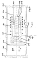
- eine erste Ausführungsform des erfindungsgemäßen Balancers komplett in Frontansicht mit Teilschnitt durch das Gehäuse;
- Fig. 2-5
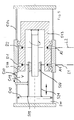
- vier weitere Ausführungsformen in Schnittdarstellung analog Fig. 1, jedoch nur schematisch den Gehäusebereich mit diversen Bauformen.
- Soweit im Folgenden identische Bezugszeichen verwendet werden, haben die bezeichneten Teile oder Aktionen eine identische Funktionsweise.
- Ein Doppelseil-Balancer 3 gemäß Fig. 1 ist mittels Aufhängung 2 an einem Deckenschienensystem 1 formschlüssig befestigt, in dem er linear längs oder (nicht dargestellt) quer verschoben werden kann.
Ein Gehäuse 4 ist beidseits durch Deckel 5 und 6 verschlossen. Die Deckel nehmen eine Spindel 8, drehfest befestigt in Deckel 5 mit Schraube 9, auf, die mit einem Führungsrohr 12 verlängert und andererseits in Deckel 6 drehfest mit Schraube 9' befestigt ist. Deckel 6 und Kolben 10 eines Pneumatikzylinders schließen den Druckraum 11 im Gehäuse ab, der durch eine nicht dargestellte Druckquelle mit Fluiddruck beaufschlagbar ist. Der Kolben 10 ist mit einem Lager durch Schrauben 17 verbunden, wobei er mittels Gleit- oder Rollenlager 15 auf dem Führungsrohr 12 längsverschieblich angeordnet und über Rollenlager 16 mit einer Seiltrommel 13 drehbeweglich gekoppelt ist.
Die Seiltrommel 13 ist andererseits mit Schrauben 14 mit einer Kugelrollspindelmutter 7 fest verbunden, die in einem Gewinde 18 der Gewindespindel 8 abrollen kann. Der Mantel der Trommel 13 trägt zwei schraubenlinienförmige Seilrillen R1 und R2 für zwei Lastseile L1 und L2, die an der Trommel mit einem Ende befestigt sind. Die Lastseile L1 und L2 verlassen das Gehäuse 4 an festgelegten Ablaufpunkten A1 und A2, die hier einen Abstand von etwa 80 - 100 mm haben. Die anderen Enden L21 und L22 der Lastseile sind durch eine Traverse T verbunden und tragen eine Dreh-Kupplung K für den Durchlass von Druckluft mit luftdichter Drehdichtung D, unter der ein Lastaufnahmemittel an Befestigung B angeordnet sein kann. Die Luftschläuche für die Steuerluft und das Lastaufnahmemittel sind mit 19 und 20 bezeichnet.
In den folgenden Figuren wiederholen sich die Bezugsziffern für funktionsgleiche Teile, unterscheiden sich jedoch durch die vorangesetzte Figurennummer. - Die Fig. 2 zeigt eine ähnliche Trommel 213 mit Seilrillen R1, R2, deren Rotation durch den Drehpfeil dargestellt ist, in einem Gehäuse 204. Im Unterschied zu Fig. 1 ist jedoch die Gewindespindel 208 mit Gewinde 218 nur an Deckel 205 befestigt ( z. B. mit einer Scheißnaht 209) und durchgreift weder den Kolben 210 noch den Druckraum 211 zum Deckel 206 hin. Die Verschieberichtungen des Kolbens 210 bei Druckbeaufschlagung bzw. Druckentlastung und damit auch der daran drehbar über Lager 216 gelagerten Trommel 213, die sich über die in der Trommel drehfest gelagerte Spindelmutter 207 auf der Gewindespindel 208 abstützt, zeigen die Pfeile V. Falls die Last auf das System kolbenseitig besser abgestützt werden soll, kann der Kolben 210 mit der Ringdichtung etwas breiter ausgeführt werden und so bei Bedarf tragend gestaltet sein.
- Fig. 3 zeigt eine Trommel 313 in Gehäuse 304, die am Umfang sowie ihrer Befestigung an Kolben 310 wie die Trommel in Fig. 2 gestaltet ist. Trommel 313 einerseits und Gewindespindel 308 mit Gewinde 318 andererseits sind drehfest miteinander verbunden , während die notwendige Spindelmutter 307 fliegend auf einem an Deckel 305 mit Schweißnaht 309 angeschweißten Rohr 321 angeordnet ist.
- Fig. 4 und Fig. 5 zeigen Seiltrommeln 413 bzw. 513 die drehbar mittels Lager 416 bzw. 516 im Gehäuse 404 bzw. 504 gelagert sind. Es sind jeweils zwei etwa im Abstand der Seildurchführungen oder Seilauslasspunkte A1 und A2 angeordnete Seilrillen R1 und R2 auf dem Umfang der Trommeln dargestellt, in denen sich die Seile L1 und L2 übereinander oder auch teils nebeneinander wickeln können. Die Kolben 410 bzw. 510 sind mit der Gewindespindel 408 (Fig. 4) bzw. mit der Spindelmutter 507 über ein Rohr 521 (Fig. 5) drehfest verbunden. Die Gewindespindel 408 hat eine Drehmomentstütze 419 bzw. das Rohr eine solche Stütze 519, wobei sich die Stütze in einem Schlitz 420 bzw. 520 des Gehäuses 404 bzw. 504 in Verschieberichtung V bewegen kann, wenn der Kolben durch den Druck im Druckraum 411 bzw. 511 verschoben wird, um jeweils die Seile L1 und L2 synchron auf die Trommel aufzuwickeln oder von ihr abzuwickeln. In Fig. 4 ist die Spindelmutter 407 wie in Fig. 1 und Fig. 2 drehfest mit der Trommel 413 verbunden; in Fig. 5 ist die Spindelmutter von dem an Kolben 510 mit Schweißnaht 509 angeschweißten Rohr 521 formschlüssig und drehfest gehalten.
Claims (8)
- Hebezeug nach Art eines Seilbalancers mit- einem aufhängbaren Gehäuse und- einer im Gehäuse angeordneten Gewindespindel,- einem durch Fluiddruck im Gehäuse längsverschiebbaren Kolben und- einer Spindelmutter, die in direkter Wirkverbindung mit der Gewindespindel steht und- einer Seiltrommel für ein am Trommelumfang in einer Seilrille geführtes Lastseil, das an einem festen Ablaufpunkt aus dem Gehäuse austritt, wobei die Seiltrommel drehbar mit dem Kolben verbunden ist,dadurch gekennzeichnet, dass am Umfang der Seiltrommel (13, 213, 313, 413, 513) zwei Seilrillen (R1, R2) für zwei etwa parallel geführte Lastseile (L1, L2) angeordnet sind, die an zwei zueinander beabstandeten Ablaufpunkten (A1, A2) aus dem Gehäuse (4, 204, 304, 404, 504) herausgeführt sind.
- Hebezeug nach Anspruch 1, dadurch gekennzeichnet, dass die Spindelmutter (7, 207, 407) drehfest mit der Seiltrommel (13, 213, 413) verbunden ist.
- Hebezeug nach Anspruch 1 oder 2, dadurch gekennzeichnet, dass die Spindelmutter (307, 507) über eine Drehmomentenstütze indirekt mit dem Gehäuse (307, 507) gekoppelt ist und über die Gewindespindel (308, 508) mit der Seiltrommel (313, 513) in Wirkverbindung steht.
- Hebezeug nach einem der vorhergehenden Ansprüche, dadurch gekennzeichnet, dass die Spindelmutter (7, 207, 307, 407, 507) als Kugelrollspindel ausgebildet ist.
- Hebezeug nach einem der vorhergehenden Ansprüche, dadurch gekennzeichnet, dass die zwei Seilrillen (R1, R2) am Umfang der Seiltrommel (13, 213, 313) nach Art einer zweigängigen Schraubenlinie ausgebildet sind.
- Hebezeug nach einem der vorhergehenden Ansprüche, dadurch gekennzeichnet, dass beide Lastseile (L1, L2) knapp oberhalb ihres die Last tragenden Endes (L21, L22) durch eine ihren Abstand überbrückende Traverse (T) verbunden sind.
- Hebezeug nach einem der vorhergehenden Ansprüche, dadurch gekennzeichnet, dass beide Lastseile (L1, L2) gemeinsam oder jeweils ein Lastaufnahmemittel haben.
- Hebezeug nach einem der vorhergehenden Ansprüche, dadurch gekennzeichnet, dass zwischen Lastaufnahmemittel und dem Ende des Lastseiles (L21, L22) eine luftdichte Dreh-Kupplung (K) für die Durchführung von Druckluft zur Last oder dem Lastaufnahmemittel angeordnet ist.
Priority Applications (1)
| Application Number | Priority Date | Filing Date | Title |
|---|---|---|---|
| DE200420006138 DE202004006138U1 (de) | 2004-03-22 | 2004-03-22 | Doppelseilbalancer |
Applications Claiming Priority (2)
| Application Number | Priority Date | Filing Date | Title |
|---|---|---|---|
| DE10312847A DE10312847A1 (de) | 2003-03-21 | 2003-03-21 | Doppelseilbalancer |
| DE10312847 | 2003-03-21 |
Publications (2)
| Publication Number | Publication Date |
|---|---|
| EP1460025A1 true EP1460025A1 (de) | 2004-09-22 |
| EP1460025B1 EP1460025B1 (de) | 2006-12-13 |
Family
ID=32798043
Family Applications (1)
| Application Number | Title | Priority Date | Filing Date |
|---|---|---|---|
| EP04006788A Expired - Lifetime EP1460025B1 (de) | 2003-03-21 | 2004-03-22 | Hebezeug mit zwei Lastseilen |
Country Status (4)
| Country | Link |
|---|---|
| EP (1) | EP1460025B1 (de) |
| AT (1) | ATE348072T1 (de) |
| DE (2) | DE10312847A1 (de) |
| ES (1) | ES2277651T3 (de) |
Cited By (3)
| Publication number | Priority date | Publication date | Assignee | Title |
|---|---|---|---|---|
| GB1469964A (en) * | 1973-03-26 | 1977-04-14 | Linde Ag | Coke cooling apparatus |
| CN101602472B (zh) * | 2008-06-13 | 2011-05-11 | 赵灯 | 一体化液压分段阻尼卷筒 |
| US9850112B2 (en) | 2013-04-17 | 2017-12-26 | Parkburn Precision Handling Systems Limited | Load bearing apparatus and method |
Families Citing this family (7)
| Publication number | Priority date | Publication date | Assignee | Title |
|---|---|---|---|---|
| DE102007008973A1 (de) | 2007-02-21 | 2008-10-30 | Strödter, Wilhelm | Brems-Positioniersystem für Hebezeuge |
| EP2133303A1 (de) | 2008-06-11 | 2009-12-16 | Wilhelm Strödter | Brems-Positioniersystem für Hebezeuge |
| DE102011003341B4 (de) | 2011-01-28 | 2014-08-28 | Wilhelm Strödter | Knickarmgerät mit momentenstabilem Seilbalancer |
| DE202011002066U1 (de) | 2011-01-28 | 2011-04-28 | Strödter, Wilhelm | Knickarmgerät mit momentenstabilem Seilbalancer |
| DE202013006584U1 (de) * | 2013-07-22 | 2014-10-23 | Liebherr-Werk Ehingen Gmbh | Ballastvorrichtung zur Erzeugung einer Windenvorspannung |
| DE202017000487U1 (de) | 2017-01-28 | 2017-03-17 | KMHP Engineering GmbH | Seilzug-Ausgleichsheber |
| DE102020100578A1 (de) * | 2020-01-13 | 2021-07-15 | sachs products GmbH | Seilbalancer |
Citations (3)
| Publication number | Priority date | Publication date | Assignee | Title |
|---|---|---|---|---|
| US5522581A (en) * | 1994-01-13 | 1996-06-04 | Zimmerman International Corp. | Balancing hoist and material handling system |
| US5553832A (en) * | 1993-03-12 | 1996-09-10 | Knight Industries, Inc. | Safety device for an air balancing hoist |
| US6042087A (en) * | 1997-03-15 | 2000-03-28 | Theodor Kromer Gmbh, Unternehmensgruppe Unican | Device for equalizing weight of a hanging load |
-
2003
- 2003-03-21 DE DE10312847A patent/DE10312847A1/de not_active Withdrawn
-
2004
- 2004-03-22 EP EP04006788A patent/EP1460025B1/de not_active Expired - Lifetime
- 2004-03-22 AT AT04006788T patent/ATE348072T1/de active
- 2004-03-22 DE DE502004002261T patent/DE502004002261D1/de not_active Expired - Lifetime
- 2004-03-22 ES ES04006788T patent/ES2277651T3/es not_active Expired - Lifetime
Patent Citations (3)
| Publication number | Priority date | Publication date | Assignee | Title |
|---|---|---|---|---|
| US5553832A (en) * | 1993-03-12 | 1996-09-10 | Knight Industries, Inc. | Safety device for an air balancing hoist |
| US5522581A (en) * | 1994-01-13 | 1996-06-04 | Zimmerman International Corp. | Balancing hoist and material handling system |
| US6042087A (en) * | 1997-03-15 | 2000-03-28 | Theodor Kromer Gmbh, Unternehmensgruppe Unican | Device for equalizing weight of a hanging load |
Cited By (3)
| Publication number | Priority date | Publication date | Assignee | Title |
|---|---|---|---|---|
| GB1469964A (en) * | 1973-03-26 | 1977-04-14 | Linde Ag | Coke cooling apparatus |
| CN101602472B (zh) * | 2008-06-13 | 2011-05-11 | 赵灯 | 一体化液压分段阻尼卷筒 |
| US9850112B2 (en) | 2013-04-17 | 2017-12-26 | Parkburn Precision Handling Systems Limited | Load bearing apparatus and method |
Also Published As
| Publication number | Publication date |
|---|---|
| ES2277651T3 (es) | 2007-07-16 |
| DE502004002261D1 (de) | 2007-01-25 |
| ATE348072T1 (de) | 2007-01-15 |
| EP1460025B1 (de) | 2006-12-13 |
| DE10312847A1 (de) | 2004-09-30 |
Similar Documents
| Publication | Publication Date | Title |
|---|---|---|
| AT520091B1 (de) | Transporteinrichtung für einen Kran | |
| DE10343079B3 (de) | Winde für eine Baumaschine | |
| EP3424871A2 (de) | Seilwindenanordnung | |
| EP3038966B1 (de) | Drallfänger | |
| EP1460025B1 (de) | Hebezeug mit zwei Lastseilen | |
| EP3620425A1 (de) | Verfahrbarer personenlift | |
| DE2831789A1 (de) | Derrick-kran | |
| WO2019179870A1 (de) | Gefederte hebevorrichtung für einen kran | |
| DE2506914A1 (de) | Teleskopausleger mit minimierter biegebeanspruchung | |
| DE20102052U1 (de) | Einschienen-Teleskopträger | |
| EP3590881A1 (de) | Transporteinrichtung | |
| DE202004006138U1 (de) | Doppelseilbalancer | |
| DE3016156C2 (de) | Hubgerüst mit wenigstens einem ausfahrbaren Teil und einem Lastträger zur Handhabung der Last | |
| EP3652102B1 (de) | Umlenkrolle in einem zugmitteltrieb | |
| DE3126206C2 (de) | ||
| DE202009007364U1 (de) | Landfahrzeug | |
| DE102015203339B4 (de) | Vorrichtung zum Ausgleich einer Verdrehung von Seilen | |
| EP3992137B1 (de) | Selbstfahrender laufwagen, insbesondere für den transport von material wie holz und dergleichen, und eine seilbahnanlage mit einem selbstfahrenden laufwagen | |
| EP2785540B1 (de) | Versteckvorrichtung | |
| DE102013113574A1 (de) | Hubgerüst mit hydraulikfreiem Hubantrieb | |
| DE3209201C2 (de) | ||
| EP3539917A1 (de) | Trommelfördermaschine | |
| DE10237873B3 (de) | Gewichtsausgleichsvorrichtung | |
| EP3077320B1 (de) | Aufzugsanlage | |
| DE202005021696U1 (de) | Balancer zur Lastenbewegung |
Legal Events
| Date | Code | Title | Description |
|---|---|---|---|
| PUAI | Public reference made under article 153(3) epc to a published international application that has entered the european phase |
Free format text: ORIGINAL CODE: 0009012 |
|
| AK | Designated contracting states |
Kind code of ref document: A1 Designated state(s): AT BE BG CH CY CZ DE DK EE ES FI FR GB GR HU IE IT LI LU MC NL PL PT RO SE SI SK TR |
|
| AX | Request for extension of the european patent |
Extension state: AL LT LV MK |
|
| 17P | Request for examination filed |
Effective date: 20050214 |
|
| AKX | Designation fees paid |
Designated state(s): AT BE BG CH CY CZ DE DK EE ES FI FR GB GR HU IE IT LI LU MC NL PL PT RO SE SI SK TR |
|
| GRAP | Despatch of communication of intention to grant a patent |
Free format text: ORIGINAL CODE: EPIDOSNIGR1 |
|
| GRAS | Grant fee paid |
Free format text: ORIGINAL CODE: EPIDOSNIGR3 |
|
| GRAA | (expected) grant |
Free format text: ORIGINAL CODE: 0009210 |
|
| AK | Designated contracting states |
Kind code of ref document: B1 Designated state(s): AT BE BG CH CY CZ DE DK EE ES FI FR GB GR HU IE IT LI LU MC NL PL PT RO SE SI SK TR |
|
| PG25 | Lapsed in a contracting state [announced via postgrant information from national office to epo] |
Ref country code: CZ Free format text: LAPSE BECAUSE OF FAILURE TO SUBMIT A TRANSLATION OF THE DESCRIPTION OR TO PAY THE FEE WITHIN THE PRESCRIBED TIME-LIMIT Effective date: 20061213 Ref country code: IE Free format text: LAPSE BECAUSE OF FAILURE TO SUBMIT A TRANSLATION OF THE DESCRIPTION OR TO PAY THE FEE WITHIN THE PRESCRIBED TIME-LIMIT Effective date: 20061213 Ref country code: PL Free format text: LAPSE BECAUSE OF FAILURE TO SUBMIT A TRANSLATION OF THE DESCRIPTION OR TO PAY THE FEE WITHIN THE PRESCRIBED TIME-LIMIT Effective date: 20061213 Ref country code: RO Free format text: LAPSE BECAUSE OF FAILURE TO SUBMIT A TRANSLATION OF THE DESCRIPTION OR TO PAY THE FEE WITHIN THE PRESCRIBED TIME-LIMIT Effective date: 20061213 Ref country code: FI Free format text: LAPSE BECAUSE OF FAILURE TO SUBMIT A TRANSLATION OF THE DESCRIPTION OR TO PAY THE FEE WITHIN THE PRESCRIBED TIME-LIMIT Effective date: 20061213 Ref country code: SI Free format text: LAPSE BECAUSE OF FAILURE TO SUBMIT A TRANSLATION OF THE DESCRIPTION OR TO PAY THE FEE WITHIN THE PRESCRIBED TIME-LIMIT Effective date: 20061213 Ref country code: SK Free format text: LAPSE BECAUSE OF FAILURE TO SUBMIT A TRANSLATION OF THE DESCRIPTION OR TO PAY THE FEE WITHIN THE PRESCRIBED TIME-LIMIT Effective date: 20061213 Ref country code: DK Free format text: LAPSE BECAUSE OF FAILURE TO SUBMIT A TRANSLATION OF THE DESCRIPTION OR TO PAY THE FEE WITHIN THE PRESCRIBED TIME-LIMIT Effective date: 20061213 |
|
| REG | Reference to a national code |
Ref country code: GB Ref legal event code: FG4D Free format text: NOT ENGLISH |
|
| REG | Reference to a national code |
Ref country code: CH Ref legal event code: EP |
|
| REG | Reference to a national code |
Ref country code: IE Ref legal event code: FG4D Free format text: LANGUAGE OF EP DOCUMENT: GERMAN |
|
| REF | Corresponds to: |
Ref document number: 502004002261 Country of ref document: DE Date of ref document: 20070125 Kind code of ref document: P |
|
| REG | Reference to a national code |
Ref country code: DE Ref legal event code: R096 Ref document number: 502004002261 Country of ref document: DE Effective date: 20070125 |
|
| PG25 | Lapsed in a contracting state [announced via postgrant information from national office to epo] |
Ref country code: SE Free format text: LAPSE BECAUSE OF FAILURE TO SUBMIT A TRANSLATION OF THE DESCRIPTION OR TO PAY THE FEE WITHIN THE PRESCRIBED TIME-LIMIT Effective date: 20070313 Ref country code: BG Free format text: LAPSE BECAUSE OF FAILURE TO SUBMIT A TRANSLATION OF THE DESCRIPTION OR TO PAY THE FEE WITHIN THE PRESCRIBED TIME-LIMIT Effective date: 20070313 |
|
| GBT | Gb: translation of ep patent filed (gb section 77(6)(a)/1977) |
Effective date: 20070314 |
|
| PG25 | Lapsed in a contracting state [announced via postgrant information from national office to epo] |
Ref country code: PT Free format text: LAPSE BECAUSE OF FAILURE TO SUBMIT A TRANSLATION OF THE DESCRIPTION OR TO PAY THE FEE WITHIN THE PRESCRIBED TIME-LIMIT Effective date: 20070514 |
|
| REG | Reference to a national code |
Ref country code: ES Ref legal event code: FG2A Ref document number: 2277651 Country of ref document: ES Kind code of ref document: T3 |
|
| ET | Fr: translation filed | ||
| PLBE | No opposition filed within time limit |
Free format text: ORIGINAL CODE: 0009261 |
|
| STAA | Information on the status of an ep patent application or granted ep patent |
Free format text: STATUS: NO OPPOSITION FILED WITHIN TIME LIMIT |
|
| 26N | No opposition filed |
Effective date: 20070914 |
|
| REG | Reference to a national code |
Ref country code: DE Ref legal event code: R097 Ref document number: 502004002261 Country of ref document: DE Effective date: 20070913 |
|
| PG25 | Lapsed in a contracting state [announced via postgrant information from national office to epo] |
Ref country code: MC Free format text: LAPSE BECAUSE OF NON-PAYMENT OF DUE FEES Effective date: 20070331 |
|
| PG25 | Lapsed in a contracting state [announced via postgrant information from national office to epo] |
Ref country code: GR Free format text: LAPSE BECAUSE OF FAILURE TO SUBMIT A TRANSLATION OF THE DESCRIPTION OR TO PAY THE FEE WITHIN THE PRESCRIBED TIME-LIMIT Effective date: 20070314 |
|
| PG25 | Lapsed in a contracting state [announced via postgrant information from national office to epo] |
Ref country code: EE Free format text: LAPSE BECAUSE OF FAILURE TO SUBMIT A TRANSLATION OF THE DESCRIPTION OR TO PAY THE FEE WITHIN THE PRESCRIBED TIME-LIMIT Effective date: 20061213 |
|
| PGFP | Annual fee paid to national office [announced via postgrant information from national office to epo] |
Ref country code: ES Payment date: 20090324 Year of fee payment: 6 |
|
| PGFP | Annual fee paid to national office [announced via postgrant information from national office to epo] |
Ref country code: CH Payment date: 20090316 Year of fee payment: 6 Ref country code: GB Payment date: 20090325 Year of fee payment: 6 |
|
| PG25 | Lapsed in a contracting state [announced via postgrant information from national office to epo] |
Ref country code: LU Free format text: LAPSE BECAUSE OF NON-PAYMENT OF DUE FEES Effective date: 20070322 Ref country code: CY Free format text: LAPSE BECAUSE OF FAILURE TO SUBMIT A TRANSLATION OF THE DESCRIPTION OR TO PAY THE FEE WITHIN THE PRESCRIBED TIME-LIMIT Effective date: 20061213 |
|
| PG25 | Lapsed in a contracting state [announced via postgrant information from national office to epo] |
Ref country code: TR Free format text: LAPSE BECAUSE OF FAILURE TO SUBMIT A TRANSLATION OF THE DESCRIPTION OR TO PAY THE FEE WITHIN THE PRESCRIBED TIME-LIMIT Effective date: 20061213 Ref country code: HU Free format text: LAPSE BECAUSE OF FAILURE TO SUBMIT A TRANSLATION OF THE DESCRIPTION OR TO PAY THE FEE WITHIN THE PRESCRIBED TIME-LIMIT Effective date: 20070614 |
|
| PGFP | Annual fee paid to national office [announced via postgrant information from national office to epo] |
Ref country code: BE Payment date: 20090430 Year of fee payment: 6 |
|
| BERE | Be: lapsed |
Owner name: STRODTER HANDHABUNGSTECHNIK G.M.B.H. Effective date: 20100331 |
|
| REG | Reference to a national code |
Ref country code: CH Ref legal event code: PL |
|
| GBPC | Gb: european patent ceased through non-payment of renewal fee |
Effective date: 20100322 |
|
| PG25 | Lapsed in a contracting state [announced via postgrant information from national office to epo] |
Ref country code: BE Free format text: LAPSE BECAUSE OF NON-PAYMENT OF DUE FEES Effective date: 20100331 Ref country code: LI Free format text: LAPSE BECAUSE OF NON-PAYMENT OF DUE FEES Effective date: 20100331 Ref country code: CH Free format text: LAPSE BECAUSE OF NON-PAYMENT OF DUE FEES Effective date: 20100331 |
|
| PG25 | Lapsed in a contracting state [announced via postgrant information from national office to epo] |
Ref country code: GB Free format text: LAPSE BECAUSE OF NON-PAYMENT OF DUE FEES Effective date: 20100322 |
|
| REG | Reference to a national code |
Ref country code: ES Ref legal event code: FD2A Effective date: 20110415 |
|
| PG25 | Lapsed in a contracting state [announced via postgrant information from national office to epo] |
Ref country code: ES Free format text: LAPSE BECAUSE OF NON-PAYMENT OF DUE FEES Effective date: 20110404 |
|
| PG25 | Lapsed in a contracting state [announced via postgrant information from national office to epo] |
Ref country code: ES Free format text: LAPSE BECAUSE OF NON-PAYMENT OF DUE FEES Effective date: 20100323 |
|
| REG | Reference to a national code |
Ref country code: FR Ref legal event code: PLFP Year of fee payment: 13 |
|
| REG | Reference to a national code |
Ref country code: FR Ref legal event code: PLFP Year of fee payment: 14 |
|
| PGFP | Annual fee paid to national office [announced via postgrant information from national office to epo] |
Ref country code: NL Payment date: 20170323 Year of fee payment: 14 Ref country code: FR Payment date: 20170323 Year of fee payment: 14 |
|
| PGFP | Annual fee paid to national office [announced via postgrant information from national office to epo] |
Ref country code: AT Payment date: 20170322 Year of fee payment: 14 |
|
| PGFP | Annual fee paid to national office [announced via postgrant information from national office to epo] |
Ref country code: IT Payment date: 20170323 Year of fee payment: 14 |
|
| REG | Reference to a national code |
Ref country code: NL Ref legal event code: MM Effective date: 20180401 |
|
| REG | Reference to a national code |
Ref country code: AT Ref legal event code: MM01 Ref document number: 348072 Country of ref document: AT Kind code of ref document: T Effective date: 20180322 |
|
| PG25 | Lapsed in a contracting state [announced via postgrant information from national office to epo] |
Ref country code: NL Free format text: LAPSE BECAUSE OF NON-PAYMENT OF DUE FEES Effective date: 20180401 |
|
| PG25 | Lapsed in a contracting state [announced via postgrant information from national office to epo] |
Ref country code: AT Free format text: LAPSE BECAUSE OF NON-PAYMENT OF DUE FEES Effective date: 20180322 |
|
| PG25 | Lapsed in a contracting state [announced via postgrant information from national office to epo] |
Ref country code: IT Free format text: LAPSE BECAUSE OF NON-PAYMENT OF DUE FEES Effective date: 20180322 |
|
| PG25 | Lapsed in a contracting state [announced via postgrant information from national office to epo] |
Ref country code: FR Free format text: LAPSE BECAUSE OF NON-PAYMENT OF DUE FEES Effective date: 20180331 |
|
| REG | Reference to a national code |
Ref country code: DE Ref legal event code: R082 Ref document number: 502004002261 Country of ref document: DE Representative=s name: ETL IP PATENTANWALTSGESELLSCHAFT MBH, DE Ref country code: DE Ref legal event code: R082 Ref document number: 502004002261 Country of ref document: DE Representative=s name: ETL WABLAT & KOLLEGEN PATENT- UND RECHTSANWALT, DE Ref country code: DE Ref legal event code: R082 Ref document number: 502004002261 Country of ref document: DE Representative=s name: ETL IP PATENT- UND RECHTSANWALTSGESELLSCHAFT M, DE |
|
| REG | Reference to a national code |
Ref country code: DE Ref legal event code: R082 Ref document number: 502004002261 Country of ref document: DE Representative=s name: ETL IP PATENTANWALTSGESELLSCHAFT MBH, DE Ref country code: DE Ref legal event code: R082 Ref document number: 502004002261 Country of ref document: DE Representative=s name: ETL IP PATENT- UND RECHTSANWALTSGESELLSCHAFT M, DE |
|
| PGFP | Annual fee paid to national office [announced via postgrant information from national office to epo] |
Ref country code: DE Payment date: 20230419 Year of fee payment: 20 |
|
| REG | Reference to a national code |
Ref country code: DE Ref legal event code: R071 Ref document number: 502004002261 Country of ref document: DE |