EP1459773B1 - Mikrostrukturierte Trennvorrichtung und mikrofluidisches Verfahren zum Abtrennen von flüssigen Bestandteilen aus einer Flüssigkeit, die Partikel enthält - Google Patents
Mikrostrukturierte Trennvorrichtung und mikrofluidisches Verfahren zum Abtrennen von flüssigen Bestandteilen aus einer Flüssigkeit, die Partikel enthält Download PDFInfo
- Publication number
- EP1459773B1 EP1459773B1 EP04006294A EP04006294A EP1459773B1 EP 1459773 B1 EP1459773 B1 EP 1459773B1 EP 04006294 A EP04006294 A EP 04006294A EP 04006294 A EP04006294 A EP 04006294A EP 1459773 B1 EP1459773 B1 EP 1459773B1
- Authority
- EP
- European Patent Office
- Prior art keywords
- separation
- separation device
- liquid
- transport channel
- region
- Prior art date
- Legal status (The legal status is an assumption and is not a legal conclusion. Google has not performed a legal analysis and makes no representation as to the accuracy of the status listed.)
- Expired - Lifetime
Links
Images
Classifications
-
- B—PERFORMING OPERATIONS; TRANSPORTING
- B01—PHYSICAL OR CHEMICAL PROCESSES OR APPARATUS IN GENERAL
- B01L—CHEMICAL OR PHYSICAL LABORATORY APPARATUS FOR GENERAL USE
- B01L3/00—Containers or dishes for laboratory use, e.g. laboratory glassware; Droppers
- B01L3/50—Containers for the purpose of retaining a material to be analysed, e.g. test tubes
- B01L3/502—Containers for the purpose of retaining a material to be analysed, e.g. test tubes with fluid transport, e.g. in multi-compartment structures
- B01L3/5027—Containers for the purpose of retaining a material to be analysed, e.g. test tubes with fluid transport, e.g. in multi-compartment structures by integrated microfluidic structures, i.e. dimensions of channels and chambers are such that surface tension forces are important, e.g. lab-on-a-chip
- B01L3/502753—Containers for the purpose of retaining a material to be analysed, e.g. test tubes with fluid transport, e.g. in multi-compartment structures by integrated microfluidic structures, i.e. dimensions of channels and chambers are such that surface tension forces are important, e.g. lab-on-a-chip characterised by bulk separation arrangements on lab-on-a-chip devices, e.g. for filtration or centrifugation
-
- B—PERFORMING OPERATIONS; TRANSPORTING
- B01—PHYSICAL OR CHEMICAL PROCESSES OR APPARATUS IN GENERAL
- B01D—SEPARATION
- B01D61/00—Processes of separation using semi-permeable membranes, e.g. dialysis, osmosis or ultrafiltration; Apparatus, accessories or auxiliary operations specially adapted therefor
- B01D61/14—Ultrafiltration; Microfiltration
- B01D61/18—Apparatus therefor
-
- B—PERFORMING OPERATIONS; TRANSPORTING
- B01—PHYSICAL OR CHEMICAL PROCESSES OR APPARATUS IN GENERAL
- B01L—CHEMICAL OR PHYSICAL LABORATORY APPARATUS FOR GENERAL USE
- B01L3/00—Containers or dishes for laboratory use, e.g. laboratory glassware; Droppers
- B01L3/50—Containers for the purpose of retaining a material to be analysed, e.g. test tubes
- B01L3/502—Containers for the purpose of retaining a material to be analysed, e.g. test tubes with fluid transport, e.g. in multi-compartment structures
- B01L3/5027—Containers for the purpose of retaining a material to be analysed, e.g. test tubes with fluid transport, e.g. in multi-compartment structures by integrated microfluidic structures, i.e. dimensions of channels and chambers are such that surface tension forces are important, e.g. lab-on-a-chip
- B01L3/502746—Containers for the purpose of retaining a material to be analysed, e.g. test tubes with fluid transport, e.g. in multi-compartment structures by integrated microfluidic structures, i.e. dimensions of channels and chambers are such that surface tension forces are important, e.g. lab-on-a-chip characterised by the means for controlling flow resistance, e.g. flow controllers, baffles or throttle valves
-
- B—PERFORMING OPERATIONS; TRANSPORTING
- B01—PHYSICAL OR CHEMICAL PROCESSES OR APPARATUS IN GENERAL
- B01L—CHEMICAL OR PHYSICAL LABORATORY APPARATUS FOR GENERAL USE
- B01L3/00—Containers or dishes for laboratory use, e.g. laboratory glassware; Droppers
- B01L3/50—Containers for the purpose of retaining a material to be analysed, e.g. test tubes
- B01L3/502—Containers for the purpose of retaining a material to be analysed, e.g. test tubes with fluid transport, e.g. in multi-compartment structures
- B01L3/5027—Containers for the purpose of retaining a material to be analysed, e.g. test tubes with fluid transport, e.g. in multi-compartment structures by integrated microfluidic structures, i.e. dimensions of channels and chambers are such that surface tension forces are important, e.g. lab-on-a-chip
- B01L3/502761—Containers for the purpose of retaining a material to be analysed, e.g. test tubes with fluid transport, e.g. in multi-compartment structures by integrated microfluidic structures, i.e. dimensions of channels and chambers are such that surface tension forces are important, e.g. lab-on-a-chip specially adapted for handling suspended solids or molecules independently from the bulk fluid flow, e.g. for trapping or sorting beads or physically stretching molecules
-
- G—PHYSICS
- G01—MEASURING; TESTING
- G01N—INVESTIGATING OR ANALYSING MATERIALS BY DETERMINING THEIR CHEMICAL OR PHYSICAL PROPERTIES
- G01N33/00—Investigating or analysing materials by specific methods not covered by groups G01N1/00 - G01N31/00
- G01N33/48—Biological material, e.g. blood, urine; Haemocytometers
- G01N33/483—Physical analysis of biological material
- G01N33/487—Physical analysis of biological material of liquid biological material
- G01N33/49—Blood
- G01N33/491—Blood by separating the blood components
-
- B—PERFORMING OPERATIONS; TRANSPORTING
- B01—PHYSICAL OR CHEMICAL PROCESSES OR APPARATUS IN GENERAL
- B01L—CHEMICAL OR PHYSICAL LABORATORY APPARATUS FOR GENERAL USE
- B01L2200/00—Solutions for specific problems relating to chemical or physical laboratory apparatus
- B01L2200/06—Fluid handling related problems
- B01L2200/0647—Handling flowable solids, e.g. microscopic beads, cells, particles
- B01L2200/0668—Trapping microscopic beads
-
- B—PERFORMING OPERATIONS; TRANSPORTING
- B01—PHYSICAL OR CHEMICAL PROCESSES OR APPARATUS IN GENERAL
- B01L—CHEMICAL OR PHYSICAL LABORATORY APPARATUS FOR GENERAL USE
- B01L2400/00—Moving or stopping fluids
- B01L2400/04—Moving fluids with specific forces or mechanical means
- B01L2400/0403—Moving fluids with specific forces or mechanical means specific forces
- B01L2400/0406—Moving fluids with specific forces or mechanical means specific forces capillary forces
-
- B—PERFORMING OPERATIONS; TRANSPORTING
- B01—PHYSICAL OR CHEMICAL PROCESSES OR APPARATUS IN GENERAL
- B01L—CHEMICAL OR PHYSICAL LABORATORY APPARATUS FOR GENERAL USE
- B01L2400/00—Moving or stopping fluids
- B01L2400/08—Regulating or influencing the flow resistance
- B01L2400/084—Passive control of flow resistance
- B01L2400/086—Passive control of flow resistance using baffles or other fixed flow obstructions
-
- Y—GENERAL TAGGING OF NEW TECHNOLOGICAL DEVELOPMENTS; GENERAL TAGGING OF CROSS-SECTIONAL TECHNOLOGIES SPANNING OVER SEVERAL SECTIONS OF THE IPC; TECHNICAL SUBJECTS COVERED BY FORMER USPC CROSS-REFERENCE ART COLLECTIONS [XRACs] AND DIGESTS
- Y10—TECHNICAL SUBJECTS COVERED BY FORMER USPC
- Y10T—TECHNICAL SUBJECTS COVERED BY FORMER US CLASSIFICATION
- Y10T436/00—Chemistry: analytical and immunological testing
- Y10T436/25—Chemistry: analytical and immunological testing including sample preparation
Definitions
- the invention relates to a microstructured separation device and a microfluidic method for separating liquid components from a liquid containing particles.
- Such a device is used, for example, to isolate blood plasma from the cellular constituents (hematocrit) contained in the blood.
- human blood is made up of the liquid blood plasma, which makes up about 55% of human blood, and on the other, the cellular constituents, the hematocrit, which make up about 45% of human blood.
- the blood plasma is a yellowish, aqueous solution of proteins, carbohydrates, lipids and mineral salts which also contains antibodies.
- the blood plasma consists of 90% water and 10% of dissolved substances.
- the hematocrit includes red blood cells (erythrocytes) and white blood cells (leucocytes). The red blood cells are the smaller particles in the blood.
- the white blood cells are disc-shaped, having a diameter of about 7.7 microns and a height of about 2 microns and are easily deformed.
- the white blood cells are larger and therefore they form the larger particles in the blood with a size of 7 to 20 microns.
- the white blood cells are not or only slightly deformable compared to the red blood cells.
- One known method of isolating blood plasma from blood is sedimentation.
- chemically treated blood is filled into a container and stored the blood in the container until the cellular components of the blood settle to the bottom of the container and left as a supernatant, the yellowish-clear blood plasma.
- the blood plasma can be skimmed off, for example by means of a pipette.
- For the sedimentation a relatively long time is necessary until the blood plasma can be recovered.
- Another method of isolating blood plasma from blood uses a laboratory centrifuge.
- the blood is put in the laboratory centrifuge, and the blood plasma and the particles in the blood are separated from each other due to the centrifugal forces.
- a laboriously designed laboratory centrifuge is required. Both sedimentation and isolation by means of a laboratory centrifuge are suitable only for relatively large volumes of blood.
- Another method is the filtering of blood by means of a mechanical filter with an open-pore filter medium whose passage openings are dimensioned so that all particles of the blood are retained.
- the blood is applied to the filter, with the particles being retained by the filter while the blood plasma enters the filter medium and seeps through the filter medium once the filter medium is fully loaded with blood plasma.
- the capacity of such filters is limited because a filter cake builds up on the filter which clogs the filter.
- Such filters have already been realized as microstructures, with the same problems with respect to the capacity or the clogging of the filter occur as with larger filters.
- the separated and in the filter medium contained plasma can be examined without being taken out of the filter medium, or it can be brought out of the filter medium by additional manipulation. If only a small amount of blood is available, this procedure becomes tedious.
- a method of isolating blood plasma from blood which utilizes the dual-effect effect.
- blood is transported by a pump through a channel, the transport channel having a branching point.
- the branching point or the channels continuing from the branching point are designed in such a way that one of the continuing channels receives a substantially larger proportion of the volume flow of the supplied blood than the other channel. Due to the dual-fung effect, a significantly larger proportion of the particles contained in the blood is transported in the channel in which the larger volume flow of blood is transported than in the other channel.
- Such a device requires on the one hand a complex structure with cascading branch points, and on the other hand, a pump to generate the necessary volume flow in the transport channels.
- a relatively large amount of liquid is needed so that a sufficient amount of the liquid components can be isolated.
- Channels in which the dual-fung effect occurs are greater than 10 ⁇ m in both directions transverse to the flow direction; they can be 25 ⁇ m deep and 50 ⁇ m wide, for example.
- the invention is based on the object to propose an apparatus and a method in which liquid components are separated from a liquid of particles contained in the liquid without filter medium and without pump or other aids.
- the device and the method should be particularly suitable for a given amount of liquid in the range of a few microliters.
- the device according to the invention has a transport channel for transporting the initially charged - particle-containing - liquid and at least one separation region for separating a portion of the liquid, wherein the separated portion is particle-free or particle-poor.
- the separation region has a microstructure that is designed to retain the larger particles and retard the smaller particles in the separation region.
- the transport channel for the particle-containing liquid may be a channel through which an unlimited amount of the particle-containing liquid can flow.
- the transport may be provided with an inlet and an outlet for the particle-containing liquid.
- a limited amount of the particulate liquid is introduced into the inlet.
- the separation area may be located at a branch point of the transport channel. The particle-containing liquid is conducted past the entrance of the separation area, and a portion of the liquid is discharged as a side stream. At the separation area, a collecting space for the separated subset of liquid can connect, which is provided with a vent opening. Further the separation region can be provided with a discharge channel for the separated subset of the liquid.
- the separation region may be located at the end of a transport channel provided with an inlet.
- the particle-containing liquid is supplied directly to the separation area, and a subset of the liquid is passed over the separation area.
- a collecting space for the separated subset of liquid can connect, which is provided with a vent opening.
- the separation region may be provided with a discharge channel for the separated subset of the liquid.
- the transport channel, the separation area and the collecting space are behind each other.
- the device according to the invention has several advantages over the devices known from the prior art.
- the liquid can be transported in the transport channel without a pump.
- capillary forces are sufficient.
- the separation area is arranged next to the transport channel.
- the entering into the separation area liquid can only contain the smaller particles. These are braked when entering the separation area or within the separation area with respect to the liquid components of the liquid in their transport speed.
- the liquid components of the liquid are transported faster through the separation area than the smaller particles.
- only the liquid constituents of the liquid can reach the end of the separation region over a relatively long period of time. During this period, an amount of the liquid ingredients is transported through the separation area sufficient for the desired analyzes.
- the deceleration of the smaller particles as they enter the separation region or within the separation region is determined by the microstructure and by surface effects, e.g. achieved by the "chromatographic effect". Because of the "chromatographic effect", liquid components of a liquid can be transported faster in a uniformly shaped channel than the particles contained therein. As a result, two consecutive phases can form in the transport direction with longer channels.
- the first phase may contain predominantly or only liquid ingredients, the second phase may contain both liquid ingredients and particles.
- the microstructure in the separation region can limit one or more passage openings. These passages have a height which is less than the height of the transport channel.
- the passages may be, for example, from 0.5 to 2 microns high.
- the red blood cells because of their deformability, can penetrate into the separation zone with a delay, while the white blood cells are too large for the passage opening.
- Several passages may be arranged in whole or in part next to each other.
- a plurality of passage openings can be arranged completely or partially in the side stream one behind the other. The width of the passage openings can decrease in the direction of the side stream, for example, from 10 microns to 2 microns. Likewise, the height of the passage openings in the side stream can decrease.
- the length of the separation region may be smaller than the width thereof, the length of the separation region extending in the direction of the side stream.
- the length may be 0.5 mm and the width 5 mm.
- a separating device according to the invention can have one or more separating regions, which can be arranged one behind the other.
- the microstructure in the separation area may be a ramp, a gap or a staircase.
- the microstructure may include spaced pillars or one or more ridges.
- the gap width may be constant in the sidestream direction, or it may decrease or increase.
- a separating device may comprise a collecting element, which adjoins the separating region in the direction of the side stream.
- This collection element can be designed as a collection chamber.
- Such a collection chamber may, for example, have a footprint of 5 mm ⁇ 5 mm at a height of 0.01 mm and a volume of 0.25 microliter.
- Reagents may be provided in this collection element. These reagents may react with the liquid ingredients entering the collection element for analysis.
- the collecting element can be connected to the environment via a removal and / or venting channel.
- the liquid contained in the collecting element can be removed therefrom by means of a pump or a syringe or the like. Via the venting channel, the air contained in the separation area and in the collecting element can escape as soon as the liquid enters the separation area and into the collecting element.
- the separating device may have an inlet which, viewed in the direction of the flow in the transport channel, lies in front of the separating region and which is connected to the transport channel.
- the separating device may have an outlet, which - seen in the transport direction - is located at the end of the transport channel.
- the separation area, the collection element or the venting channel may be followed by other microstructured elements.
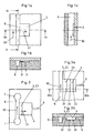
- FIGS. 1a to 1c a simplified separating device is shown, based on which the operating principle of a separating device according to the invention will be explained.
- the separation devices shown in the figures and thus also the Separators according to the FIGS. 1a to 1c are designed so that, for example, blood plasma can be separated from whole blood.
- a separating device according to the invention the blood plasma contained in the whole blood can be separated from the hematocrit contained in the blood.
- the separating device according to the invention according to the FIGS. 1a to 1c has - as well as the other separators shown in the figures - a transport channel 6 and a separation area 3.
- the submitted blood is transported in the transport channel 6 in the transporting direction 30.
- the blood can be transported by capillary forces between the beginning and the end of the transport channel 6 alone.
- a separation region 3 is arranged. In this separation region 3, the flow rate of the hematocrit slows down with respect to the flow rate of the blood plasma so that blood plasma isolated from the hematocrit collects in the transport direction 31 at the end of the separation region 3.
- Both the transport channel 6 and the separation region 3 are provided as a recess in the surface of a carrier.
- the transport channel 6 has a greater depth than the separation region 3.
- the transition between the transport channel 6 and the separation region 3 is therefore formed by a paragraph.
- the recesses, i. the transport channel 6 and the separation area 3 can be covered with a lid, which may for example consist of the same material as the carrier or of a film.
- the heel, the lid and the side walls of the separation area form the microstructure of the separation area 3 with a defined passage opening.
- This passage opening is dimensioned so that the larger cellular components are not through the passage opening can pass and be washed away by the blood flowing in the transport channel 6, and can not close the passage opening of the separation area. These components are predominantly the white blood cells.
- the passage opening is advantageously dimensioned such that smaller cellular components can only pass through the passage opening if these smaller cellular components deform and adapt to the size of the passage opening.
- the capillary forces in the separation area are greater than the capillary forces in the transport channel 6.
- a further effect, which in particular affects the separation of the blood plasma from the smaller cellular constituents of the blood in a separating device according to the invention, is the "chromatographic effect".
- the chromatographic effect causes blood plasma to be transported faster through the separation region 3 than cellular constituents, for example red blood cells, which may enter the separation region 3 but are moved more slowly in the separation region 3 than the blood plasma. Before the cellular components can reach the collection area at the end of the separation area 3, this is already completely filled with blood plasma. The red blood cells can no longer penetrate into the collection area and enter the blood plasma.
- a carrier is shown with a separating device, in which an inlet 1 and an outlet 2 are provided, which are connected to each other via the transport channel 6.
- a separation area 3 connects. This separation region 3 is flowed through in the direction 31 by the blood plasma to be separated off.
- a collecting element 4 designed as collecting element joins the separating region 3.
- Collection chamber 4 is connected via a removal and venting channel 5 with the environment.
- a syringe or a pump may be connected to remove the separated blood plasma from the collection chamber.
- the air contained in the collection chamber 4 and in the separation region 3, which is displaced into the collection chamber 4 and into the separation region 3 when the blood plasma enters, is removed via the removal and ventilation channel.
- the collecting area and the collecting chamber can be vented through an opening in the lid.
- the inlet 1, the outlet 2, the transport channel 6, the separation area 3, the collection chamber 4 and the extraction and venting channel 5 are provided as recesses in the support.
- the inlet, the transport channel 6 and the outlet 2 are configured such that blood introduced into the inlet 1 is transported from the inlet 1 via the transport channel 6 to the outlet 2 due to the capillary forces acting in the inlet 1, the transport channel 6 and the outlet 2 becomes.
- capillary forces which are greater than the capillary forces, act in the transport channel 6.
- part of the blood flowing in the transport channel is branched off into the separation region 3.
- the bottom of the carrier in the separation region 3, the side walls of the recess and the lid on the support form a passage opening whose height is less than the height of the transport channel 6. Since the height of the collection chamber 4 is greater than the height of the passage opening of the separation region 3, the microstructure of the separation region 3 is designed as a web 23.
- the height of the passage opening between web 23 and lid is dimensioned so that in particular the larger cellular components of the blood do not between the web 23 of the separation region 3 and the lid the separator can pass through.
- the blood plasma is separated from the smaller cellular components which may still be contained in the liquid due to the "chromatographic effect".
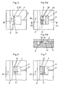
- FIGS. 3a to 10b Various separation devices are described with a transport channel 6, a separation area 3 and a collection chamber 4 and a removal and venting channel 5, as in a carrier according to Fig. 2 or in other carriers can be used accordingly.
- the separation devices of FIGS. 3a to 10b differ from that in the carrier according to Fig. 2 used separation device essentially by the configuration of the separation region 3 or by the design of the collection chamber. 4
- FIG. 4 illustrated embodiment of a separator according to the invention differs from the separator according to Fig. 2 in that, instead of a straight web 23 with edges lying parallel to the transport direction 30, a serrated web 23 'is used.
- a serrated web 23 ' is used instead of a straight web 23 with edges lying parallel to the transport direction 30.
- the columns 22 are in the separator according to the FIGS. 5a and 5b arranged in two rows with consecutive columns.
- the passage openings, which are delimited by the columns of the first row, can have the same width as the passage openings, which are delimited by the columns of the second row.
- the separator according to Fig. 5a and 5b has in the collecting chamber 4 a transverse to the transport direction 31 web 34.
- the web 34 initially accumulates the liquid in front of it. As soon as the area in front of the web 34 is completely filled, the liquid overcomes the web 34 and penetrates into the region of the collecting chamber 4 lying behind the web 34.
- the blood plasma entering the collection chamber 4 uniformly fills the collection chamber 4 and the air contained in the collection chamber 4 exits the collection chamber 4 through the venting and removal channel 5 without the formation of air bubbles.
- the columns 22 are arranged in three rows one behind the other, ie the columns of the second row are aligned with the passage openings between the columns of the first row and the columns of the third row are aligned with the passage openings between the columns of the second row.
- the columns 22 are arranged in three rows one behind the other, ie the columns of the second row are aligned with the passage openings between the columns of the first row and the columns of the third row are aligned with the passage openings between the columns of the second row.
- the passage openings between the columns of the first row have a greater width than the passage openings between the columns of the second row.
- the passage opening between the columns of the second row have a greater width than the passage openings between the columns of the third row.
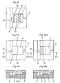
- the separator according to Fig. 8 has as microstructures both a web 23 and columns 22.
- the web 23 is provided in the region adjacent to the transport channel 6 region of the separation region 3 and extends in a zigzag shape next to the transport channel 6. Behind the web 23 staggered in three rows and placed on gap columns 22 are arranged.
- the height of the passage opening in the region of the web 23 is designed so that smaller cellular components of the blood, such as red blood cells, can pass through the gap between the web 23 and the lid, but these components are stopped by the columns 22 ,
- a separator is shown in which the separation area 3 is formed by a ramp 20.
- This ramp 20 rises from the level of the bottom of the transport channel 6. Through the passage at the end of the ramp, the smallest cellular components can not pass through.
- the front Area of the ramp 20, which adjoins directly to the transport channel 6, is constantly flushed by the blood flowing in the transport channel. Particles present in this area are washed away by the liquid flow in the transport channel 6.
- the separating device according to the Figures 10a and 10b has a separation region 3 with a microstructure, which is formed by a staircase 21.
- a staircase 21 By the stairs 21, the height between the stairs 21 and the lid is gradually reduced.
- the smallest cellular components of the blood ie in particular the red blood cells, can not pass or only delayed.
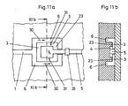
- FIG. 11a and 11b a further embodiment of a separating device according to the invention is shown.
- This separator has as inlet 1 to a channel, which is followed by a in the plan view C-shaped transport channel 6.
- the transport channel 6 is connected in the region of the web connecting the two legs of the "C".
- the transport channel 6 has two transport channel halves, which are connected to the end of the inlet 1.
- the interior of this separation area 3 is the collection chamber 4, which is connected to a withdrawal and venting channel 5, through the open side of in Top view C-shaped separation region 3 and the top view C-shaped transport channel 6 is guided.
- Both the inlet 1 and the transport channel 6 or the transport channel halves are designed such that the blood introduced into the separator via the inlet due to the forces acting in the inlet 1 and the halves of the transport channel 6 capillary forces from the end of the inlet 1 to the ends of the Halves of the transport channel 6 is transported.
- the ends of the transport channel halves are e.g. connected to an outlet which receives the excess blood from the transport channel halves.
- the separation region 3 has a microstructure which is formed by a web 23 which extends between the transport channel halves 6 and the collection chamber 4. Between the web 23 and a cover of the separation device according to the invention, which covers the channels 5, 6, the separation region 3 and the collection chamber 4, remains a passage opening which is so high that the larger cellular components can not penetrate through them.
- the web has in the transport direction 31 an extension which is dimensioned so that smaller cellular components, such as red blood cells reach the inner edge of the web 23 only when the collection chamber 4 is already completely filled with blood plasma. Once the collection chamber 4 is completely filled, the red blood cells, which are located in the separation area 3, can not be transported into the collection chamber 4 due to the stopping transport mechanisms, so that mixing of the blood plasma with red blood cells is prevented.
- the extraction and venting channel 5 comprises a capillary stop 35, which is closed by the application of an external pressure, e.g. can be overcome by a syringe or by a pump to remove the separated blood plasma from the collection chamber.
- an external pressure e.g. can be overcome by a syringe or by a pump to remove the separated blood plasma from the collection chamber.
Landscapes
- Health & Medical Sciences (AREA)
- Chemical & Material Sciences (AREA)
- Life Sciences & Earth Sciences (AREA)
- Engineering & Computer Science (AREA)
- Hematology (AREA)
- Analytical Chemistry (AREA)
- General Health & Medical Sciences (AREA)
- Chemical Kinetics & Catalysis (AREA)
- Dispersion Chemistry (AREA)
- Clinical Laboratory Science (AREA)
- Physics & Mathematics (AREA)
- Biomedical Technology (AREA)
- Water Supply & Treatment (AREA)
- Molecular Biology (AREA)
- Ecology (AREA)
- General Physics & Mathematics (AREA)
- Biophysics (AREA)
- Urology & Nephrology (AREA)
- Food Science & Technology (AREA)
- Medicinal Chemistry (AREA)
- Biochemistry (AREA)
- Fluid Mechanics (AREA)
- Immunology (AREA)
- Pathology (AREA)
- External Artificial Organs (AREA)
- Investigating Or Analysing Biological Materials (AREA)
- Medicines Containing Material From Animals Or Micro-Organisms (AREA)
- Sampling And Sample Adjustment (AREA)
- Separation Of Solids By Using Liquids Or Pneumatic Power (AREA)
Applications Claiming Priority (2)
| Application Number | Priority Date | Filing Date | Title |
|---|---|---|---|
| DE10313201 | 2003-03-21 | ||
| DE10313201A DE10313201A1 (de) | 2003-03-21 | 2003-03-21 | Mikrostrukturierte Trennvorrichtung und mikrofluidisches Verfahren zum Abtrennen von flüssigen Bestandteilen aus einer Flüssigkeit, die Partikel enthält |
Publications (2)
| Publication Number | Publication Date |
|---|---|
| EP1459773A1 EP1459773A1 (de) | 2004-09-22 |
| EP1459773B1 true EP1459773B1 (de) | 2012-05-09 |
Family
ID=32798081
Family Applications (1)
| Application Number | Title | Priority Date | Filing Date |
|---|---|---|---|
| EP04006294A Expired - Lifetime EP1459773B1 (de) | 2003-03-21 | 2004-03-17 | Mikrostrukturierte Trennvorrichtung und mikrofluidisches Verfahren zum Abtrennen von flüssigen Bestandteilen aus einer Flüssigkeit, die Partikel enthält |
Country Status (6)
| Country | Link |
|---|---|
| US (2) | US20040232074A1 (enExample) |
| EP (1) | EP1459773B1 (enExample) |
| JP (1) | JP2004283828A (enExample) |
| CN (1) | CN1613542A (enExample) |
| AT (1) | ATE556731T1 (enExample) |
| DE (1) | DE10313201A1 (enExample) |
Families Citing this family (71)
| Publication number | Priority date | Publication date | Assignee | Title |
|---|---|---|---|---|
| US6913697B2 (en) | 2001-02-14 | 2005-07-05 | Science & Technology Corporation @ Unm | Nanostructured separation and analysis devices for biological membranes |
| US7198759B2 (en) * | 2002-07-26 | 2007-04-03 | Applera Corporation | Microfluidic devices, methods, and systems |
| ES2375724T3 (es) | 2002-09-27 | 2012-03-05 | The General Hospital Corporation | Dispositivo microflu�?dico para seperación de células y sus usos. |
| US7175810B2 (en) * | 2002-11-15 | 2007-02-13 | Eksigent Technologies | Processing of particles |
| DE102004007567A1 (de) * | 2004-02-17 | 2005-09-01 | Boehringer Ingelheim Microparts Gmbh | Mikrostrukturierte Plattform und Verfahren zum Handhaben einer Flüssigkeit |
| JP4509632B2 (ja) * | 2004-04-05 | 2010-07-21 | 株式会社アドバンス | 血球分離構造物 |
| JP4587215B2 (ja) * | 2005-02-16 | 2010-11-24 | セイコーインスツル株式会社 | 成分分離機構と成分分離方法 |
| JP4548174B2 (ja) * | 2005-03-24 | 2010-09-22 | コニカミノルタエムジー株式会社 | 検査用マイクロチップおよびそれを用いた検査装置 |
| US20070196820A1 (en) | 2005-04-05 | 2007-08-23 | Ravi Kapur | Devices and methods for enrichment and alteration of cells and other particles |
| US8921102B2 (en) | 2005-07-29 | 2014-12-30 | Gpb Scientific, Llc | Devices and methods for enrichment and alteration of circulating tumor cells and other particles |
| DE102005051645B4 (de) * | 2005-10-26 | 2018-10-18 | Rapid Sampling Technologies Ag | Einrichtung zur Fraktionierung von mit Partikeln beladenen Flüssigkeiten |
| CN101454664B (zh) * | 2006-05-24 | 2013-08-21 | 国立大学法人京都大学 | 血浆分离用微流路 |
| US8137912B2 (en) | 2006-06-14 | 2012-03-20 | The General Hospital Corporation | Methods for the diagnosis of fetal abnormalities |
| EP2029779A4 (en) | 2006-06-14 | 2010-01-20 | Living Microsystems Inc | HIGHLY PARALLEL SNP GENOTYPING UTILIZATION FOR FETAL DIAGNOSIS |
| US8372584B2 (en) | 2006-06-14 | 2013-02-12 | The General Hospital Corporation | Rare cell analysis using sample splitting and DNA tags |
| US20080050739A1 (en) | 2006-06-14 | 2008-02-28 | Roland Stoughton | Diagnosis of fetal abnormalities using polymorphisms including short tandem repeats |
| JP2008089381A (ja) * | 2006-09-29 | 2008-04-17 | Fujifilm Corp | 血漿回収方法及び血漿回収器具 |
| JP4876891B2 (ja) * | 2006-12-19 | 2012-02-15 | 日本精工株式会社 | 物質分級装置及び物質分級方法 |
| JP5137551B2 (ja) * | 2006-12-28 | 2013-02-06 | キヤノン株式会社 | 生化学反応カセット |
| WO2008130032A1 (ja) * | 2007-04-19 | 2008-10-30 | The Ritsumeikan Trust | 液中粒子分級装置及び液中粒子分級方法、粒径測定装置及び粒径測定方法 |
| EP2145687B1 (en) * | 2007-05-15 | 2014-12-03 | Panasonic Corporation | Component separation device |
| JP4859804B2 (ja) * | 2007-10-04 | 2012-01-25 | パナソニック株式会社 | 分析用デバイスとこれを使用する分析装置および分析方法 |
| JP4859805B2 (ja) * | 2007-10-04 | 2012-01-25 | パナソニック株式会社 | 分析用デバイスとこれを使用する分析装置および分析方法 |
| CN102879558B (zh) * | 2007-10-04 | 2015-09-16 | 松下健康医疗器械株式会社 | 分析用仪器和使用该分析用仪器的分析装置及分析方法 |
| WO2009054473A1 (ja) * | 2007-10-26 | 2009-04-30 | Toppan Printing Co., Ltd. | 反応チップ及び反応方法、遺伝子処理装置用温度調節機構及び遺伝子処理装置 |
| JP5207709B2 (ja) * | 2007-11-08 | 2013-06-12 | パナソニック株式会社 | 分析用デバイスとこれを使用する分析装置および分析方法 |
| US9182384B2 (en) | 2007-11-08 | 2015-11-10 | Panasonic Healthcare Holdings Co., Ltd. | Analyzing device and analyzing method using same |
| US20110008776A1 (en) * | 2007-11-26 | 2011-01-13 | Atonomics A/S | Integrated separation and detection cartridge using magnetic particles with bimodal size distribution |
| JP5369111B2 (ja) * | 2007-11-26 | 2013-12-18 | アトノミックス アクティーゼルスカブ | 物理障壁を含む隔離デバイス |
| WO2009068027A1 (en) * | 2007-11-26 | 2009-06-04 | Atonomics A/S | Separation and detection device |
| US10005082B2 (en) | 2008-04-11 | 2018-06-26 | Incyto Co., Ltd. | Microfluidic circuit element comprising microfluidic channel with nano interstices and fabrication method thereof |
| KR100998535B1 (ko) * | 2008-04-11 | 2010-12-07 | 인싸이토 주식회사 | 나노틈새를 가지는 미세유체 채널이 구비된 미세유체회로소자 및 이의 제조 방법 |
| JP2011519553A (ja) * | 2008-04-23 | 2011-07-14 | パーソーティックス、インク. | 粒子を分離する方法及び装置 |
| JP4852573B2 (ja) * | 2008-06-18 | 2012-01-11 | 日本電信電話株式会社 | フローセル |
| CN103487594B (zh) | 2008-07-17 | 2015-02-18 | 松下健康医疗器械株式会社 | 分析用器件及使用该分析用器件的分析方法 |
| JP5206191B2 (ja) * | 2008-07-21 | 2013-06-12 | ブラザー工業株式会社 | 検査対象受体及び当該検査対象受体を備えた検査装置 |
| SMT201700149T1 (it) | 2008-09-20 | 2017-05-08 | Univ Leland Stanford Junior | Diagnosi non invasiva di aneuploidia fetale mediante sequenziamento |
| JP5174723B2 (ja) * | 2009-03-12 | 2013-04-03 | パナソニック株式会社 | 分析用デバイス |
| WO2011003689A2 (en) * | 2009-07-07 | 2011-01-13 | Boehringer Ingelheim Microparts Gmbh | Plasma separation reservoir |
| GB2474888A (en) * | 2009-10-30 | 2011-05-04 | Univ Dublin City | Microfluidic devices with degassing driven fluid flow |
| MX344460B (es) * | 2009-12-23 | 2016-12-14 | Cytovera Inc * | Sistema y método para la filtración de partículas. |
| KR100961874B1 (ko) * | 2010-04-05 | 2010-06-09 | 주식회사 나노엔텍 | 외부동력 없이 유체가 이동하는 유체분석용 칩 |
| KR101152791B1 (ko) * | 2010-05-10 | 2012-06-12 | 광주과학기술원 | 쯔바이파흐-풍 효과를 이용한 세포 발열량 측정 센서 및 이의 제조방법 |
| US20130288292A1 (en) * | 2011-01-11 | 2013-10-31 | Ivar Meyvantsson | Surface-tension based flow guidance in a microstructure environment |
| WO2013004673A1 (de) * | 2011-07-05 | 2013-01-10 | Boehringer Ingelheim Microparts Gmbh | Mikrofluidische struktur mit vertiefungen |
| JP5152386B2 (ja) * | 2011-10-05 | 2013-02-27 | 日本精工株式会社 | 物質分級装置及び物質分級方法 |
| EP2587248A1 (en) * | 2011-10-25 | 2013-05-01 | Koninklijke Philips Electronics N.V. | Filtering particles from blood or other media |
| WO2013061257A1 (en) * | 2011-10-25 | 2013-05-02 | Koninklijke Philips Electronics N.V. | Filtering particles from blood or other media |
| CN103959037A (zh) * | 2011-10-25 | 2014-07-30 | 皇家飞利浦有限公司 | 从血液或其他介质中过滤颗粒 |
| FI124516B (en) * | 2012-05-25 | 2014-09-30 | Kemira Oyj | A method for analyzing a sample in a fluid stream containing a solid, a system for measuring sample suspensions containing solid particles of various sizes and using them to observe or control industrial processes |
| CN102896010B (zh) * | 2012-10-26 | 2014-06-18 | 中国科学技术大学 | 一种微流控分离芯片、分离器及超滤装置 |
| KR101475440B1 (ko) * | 2012-10-29 | 2014-12-22 | 고려대학교 산학협력단 | 미세유체회로소자 |
| US8900532B2 (en) | 2012-11-16 | 2014-12-02 | The Charles Stark Draper Laboratory, Inc. | Apparatus and method for separating plasma from blood and delayed wetting |
| US9687847B1 (en) * | 2013-02-13 | 2017-06-27 | University Of South Florida | Microfluidic platforms for optical biosensing |
| US20150064153A1 (en) | 2013-03-15 | 2015-03-05 | The Trustees Of Princeton University | High efficiency microfluidic purification of stem cells to improve transplants |
| CN110186835B (zh) | 2013-03-15 | 2022-05-31 | Gpb科学有限公司 | 颗粒的片上微流体处理 |
| CN105247042B (zh) | 2013-03-15 | 2021-06-11 | 普林斯顿大学理事会 | 用于高通量纯化的方法和设备 |
| ES2539843B2 (es) | 2013-11-15 | 2015-11-16 | Universitat Politècnica De Catalunya | Dispositivo microfluídico para la separación de líquido del mismo líquido conteniendo partículas deformables sin fuentes de energía externas |
| US10073091B2 (en) | 2014-08-08 | 2018-09-11 | Ortho-Clinical Diagnostics, Inc. | Lateral flow assay device |
| TWI691344B (zh) | 2015-01-08 | 2020-04-21 | 瑞典商梅特諾瓦有限公司 | 用於無菌連接的方法及裝置 |
| KR102473981B1 (ko) | 2015-03-24 | 2022-12-05 | 프리시젼바이오 주식회사 | 시료 검사 장치 |
| US20160367918A1 (en) * | 2015-06-22 | 2016-12-22 | Fuji Electric Co., Ltd. | Filter system |
| US10976232B2 (en) | 2015-08-24 | 2021-04-13 | Gpb Scientific, Inc. | Methods and devices for multi-step cell purification and concentration |
| JP6518016B2 (ja) * | 2015-12-24 | 2019-05-22 | コーニンクレッカ フィリップス エヌ ヴェKoninklijke Philips N.V. | 細胞懸濁液の決定のための方法及びシステム |
| US10859074B2 (en) | 2016-07-22 | 2020-12-08 | Hewlett-Packard Development Company, L.P. | Microfluidic devices |
| JPWO2018212043A1 (ja) * | 2017-05-19 | 2020-04-09 | 国立大学法人大阪大学 | 流路デバイスおよび微粒子濃縮方法 |
| WO2019044610A1 (ja) * | 2017-08-30 | 2019-03-07 | 京セラ株式会社 | 粒子分離デバイスおよびそれを用いた粒子分離装置 |
| US11638918B2 (en) * | 2018-08-23 | 2023-05-02 | Truvian Sciences, Inc. | Blood plasma separation device |
| WO2020144754A1 (ja) * | 2019-01-09 | 2020-07-16 | 株式会社日立ハイテク | サイズ分布計測装置、サイズ分布計測方法、サンプル容器 |
| DE102019102822A1 (de) | 2019-02-05 | 2020-08-06 | Fraunhofer-Gesellschaft zur Förderung der angewandten Forschung e.V. | Mikrofluidikeinrichtung und Verfahren zum Abtrennen von Blutserum |
| EP4036586A4 (en) | 2019-09-27 | 2022-11-30 | FUJIFILM Corporation | TANK AND TEST KIT |
Family Cites Families (12)
| Publication number | Priority date | Publication date | Assignee | Title |
|---|---|---|---|---|
| CH671709A5 (enExample) * | 1986-07-23 | 1989-09-29 | Sulzer Ag | |
| US4753776A (en) * | 1986-10-29 | 1988-06-28 | Biotrack, Inc. | Blood separation device comprising a filter and a capillary flow pathway exiting the filter |
| US5304487A (en) * | 1992-05-01 | 1994-04-19 | Trustees Of The University Of Pennsylvania | Fluid handling in mesoscale analytical devices |
| DE4228885A1 (de) * | 1992-08-29 | 1994-03-03 | Basf Ag | Verfahren zur Herstellung von 2,6-Dimethylmorpholin aus N-(2-Hydroxypropyl)-2,6-dimethylmorpholin |
| US5922210A (en) * | 1995-06-16 | 1999-07-13 | University Of Washington | Tangential flow planar microfabricated fluid filter and method of using thereof |
| US6454945B1 (en) * | 1995-06-16 | 2002-09-24 | University Of Washington | Microfabricated devices and methods |
| JP2000262871A (ja) * | 1999-01-11 | 2000-09-26 | Kawamura Inst Of Chem Res | 微小膜分離デバイス及びその製造方法 |
| DE10046173C2 (de) * | 2000-09-08 | 2003-04-03 | Inst Chemo Biosensorik | Vorrichtung und Verfahren zur Separation von ungelösten Bestandteilen aus biologischen Flüssigkeiten |
| US6766817B2 (en) * | 2001-07-25 | 2004-07-27 | Tubarc Technologies, Llc | Fluid conduction utilizing a reversible unsaturated siphon with tubarc porosity action |
| DE10150549A1 (de) * | 2001-10-12 | 2003-04-17 | Roche Diagnostics Gmbh | Verfahren und Trennmodul zum Abtrennen von Partikeln aus einer Dispersion, insbesondere von Blutkörperchen aus Blut |
| JP2004042012A (ja) * | 2001-10-26 | 2004-02-12 | Nec Corp | 分離装置、分析システム、分離方法および分離装置の製造方法 |
| US6878271B2 (en) * | 2002-09-09 | 2005-04-12 | Cytonome, Inc. | Implementation of microfluidic components in a microfluidic system |
-
2003
- 2003-03-21 DE DE10313201A patent/DE10313201A1/de not_active Ceased
-
2004
- 2004-03-17 EP EP04006294A patent/EP1459773B1/de not_active Expired - Lifetime
- 2004-03-17 AT AT04006294T patent/ATE556731T1/de active
- 2004-03-19 US US10/804,220 patent/US20040232074A1/en not_active Abandoned
- 2004-03-19 CN CNA2004100119500A patent/CN1613542A/zh active Pending
- 2004-03-22 JP JP2004083639A patent/JP2004283828A/ja active Pending
-
2007
- 2007-06-18 US US11/812,290 patent/US20080000833A1/en not_active Abandoned
Also Published As
| Publication number | Publication date |
|---|---|
| US20040232074A1 (en) | 2004-11-25 |
| JP2004283828A (ja) | 2004-10-14 |
| US20080000833A1 (en) | 2008-01-03 |
| CN1613542A (zh) | 2005-05-11 |
| EP1459773A1 (de) | 2004-09-22 |
| ATE556731T1 (de) | 2012-05-15 |
| DE10313201A1 (de) | 2004-10-07 |
Similar Documents
| Publication | Publication Date | Title |
|---|---|---|
| EP1459773B1 (de) | Mikrostrukturierte Trennvorrichtung und mikrofluidisches Verfahren zum Abtrennen von flüssigen Bestandteilen aus einer Flüssigkeit, die Partikel enthält | |
| EP1441131B1 (de) | Verwendung eines mikrofluidischen Schalters zum Anhalten eines Flüssigkeitsstroms während eines Zeitintervalls | |
| DE69604578T2 (de) | Zentrifugiersystem zum überlaufsammeln von spärlich vorhandenen bestandteilen wie mononuklearen zellen | |
| EP0985453B1 (de) | Zentrifugenkammer für einen Zellseparator | |
| DE3710217C2 (de) | Einrichtung für eine Zentrifuge | |
| DE60036906T2 (de) | Zentrifugale trennvorrichtung und verfahren zur trennung von flüssigkeitsbestandteilen | |
| DE60132198T2 (de) | Plattentrenneinrichtung für blutbestandteile | |
| DE69605901T2 (de) | Zentrifugiersystem zm intermittierenden sammeln von mononuklearen zellen | |
| DE69626832T2 (de) | Blutbehandlungssysteme und methoden zur gewinnung von mononuklearen zellen | |
| DE4293865B4 (de) | Verbesserte Cytozentrifugiereinrichtung, Apparatur und Verfahren | |
| EP1531003B1 (de) | Mikrostrukturierte Trennvorrichtung und Verfahren zum Abtrennen von flüssigen Bestandteilen aus einer Partikel enthaltenden Flüssigkeit | |
| DE69323621T2 (de) | Vorrichtung und verfahren zur gewinnung von leukocytfreiem trombozytkonzentrat | |
| DE60023607T2 (de) | Querstromfiltrationsmembran und Verfahren zu ihrer Herstellung | |
| EP1559676B1 (de) | Mikrostrukturierte anordnung zur blasenfreien befüllung zumindest eines systems zur ableitung von flüssigkeiten, vorrichtung mit einer solchen anordnung und befüllungsverfahren | |
| EP1253977B1 (de) | Verfahren und vorrichtung zur abführung suspendierter mikropartikel aus einem fluidischen mikrosystem | |
| EP1315553B1 (de) | Vorrichtung und verfahren zur separation von ungelösten bestandteilen aus biologischen flüssigkeiten | |
| DE2612696A1 (de) | Vollmantel-dekantierzentrifuge | |
| DE69407969T2 (de) | Vorrichtung und verfahren zur trennung von plasma aus einem blutprodukt | |
| EP1802396B1 (de) | Partikelsedimentationsvorrichtung und verfahren zum durchführen einer partikelsedimentation | |
| EP1434637B1 (de) | Verfahren und trennmodul zum abtrennen von partikeln aus einer dispersion, insbesondere von blutkörperchen aus blut | |
| WO2006094752A1 (de) | Venöse blasenfalle | |
| DE2925143C2 (de) | Vorrichtung für die kontinuierliche Plasmapherese | |
| DE2342324A1 (de) | Verfahren und vorrichtung zur trennung nicht mischbarer fluide | |
| EP0302123B1 (de) | Klärapparat für flüssig-flüssig-extraktoren | |
| EP0217781A2 (de) | Einrichtung zum kontinuierlichen Trennen von flüssigen Phasen unterschiedlicher Dichte |
Legal Events
| Date | Code | Title | Description |
|---|---|---|---|
| PUAI | Public reference made under article 153(3) epc to a published international application that has entered the european phase |
Free format text: ORIGINAL CODE: 0009012 |
|
| AK | Designated contracting states |
Kind code of ref document: A1 Designated state(s): AT BE BG CH CY CZ DE DK EE ES FI FR GB GR HU IE IT LI LU MC NL PL PT RO SE SI SK TR |
|
| AX | Request for extension of the european patent |
Extension state: AL LT LV MK |
|
| 17P | Request for examination filed |
Effective date: 20050322 |
|
| AKX | Designation fees paid |
Designated state(s): AT BE BG CH CY CZ DE DK EE ES FI FR GB GR HU IE IT LI LU MC NL PL PT RO SE SI SK TR |
|
| RAP1 | Party data changed (applicant data changed or rights of an application transferred) |
Owner name: BOEHRINGER INGELHEIM MICROPARTS GMBH |
|
| GRAP | Despatch of communication of intention to grant a patent |
Free format text: ORIGINAL CODE: EPIDOSNIGR1 |
|
| RIN1 | Information on inventor provided before grant (corrected) |
Inventor name: BLANKENSTEIN, GERT, DR. Inventor name: PETERS, RALF-PETER, DR. DIPL.-PHYS. |
|
| GRAS | Grant fee paid |
Free format text: ORIGINAL CODE: EPIDOSNIGR3 |
|
| GRAA | (expected) grant |
Free format text: ORIGINAL CODE: 0009210 |
|
| AK | Designated contracting states |
Kind code of ref document: B1 Designated state(s): AT BE BG CH CY CZ DE DK EE ES FI FR GB GR HU IE IT LI LU MC NL PL PT RO SE SI SK TR |
|
| REG | Reference to a national code |
Ref country code: GB Ref legal event code: FG4D Free format text: NOT ENGLISH |
|
| REG | Reference to a national code |
Ref country code: CH Ref legal event code: EP Ref country code: AT Ref legal event code: REF Ref document number: 556731 Country of ref document: AT Kind code of ref document: T Effective date: 20120515 |
|
| REG | Reference to a national code |
Ref country code: IE Ref legal event code: FG4D Free format text: LANGUAGE OF EP DOCUMENT: GERMAN |
|
| REG | Reference to a national code |
Ref country code: DE Ref legal event code: R096 Ref document number: 502004013495 Country of ref document: DE Effective date: 20120712 |
|
| REG | Reference to a national code |
Ref country code: NL Ref legal event code: VDEP Effective date: 20120509 |
|
| PG25 | Lapsed in a contracting state [announced via postgrant information from national office to epo] |
Ref country code: FI Free format text: LAPSE BECAUSE OF FAILURE TO SUBMIT A TRANSLATION OF THE DESCRIPTION OR TO PAY THE FEE WITHIN THE PRESCRIBED TIME-LIMIT Effective date: 20120509 Ref country code: SE Free format text: LAPSE BECAUSE OF FAILURE TO SUBMIT A TRANSLATION OF THE DESCRIPTION OR TO PAY THE FEE WITHIN THE PRESCRIBED TIME-LIMIT Effective date: 20120509 Ref country code: CY Free format text: LAPSE BECAUSE OF FAILURE TO SUBMIT A TRANSLATION OF THE DESCRIPTION OR TO PAY THE FEE WITHIN THE PRESCRIBED TIME-LIMIT Effective date: 20120509 Ref country code: PL Free format text: LAPSE BECAUSE OF FAILURE TO SUBMIT A TRANSLATION OF THE DESCRIPTION OR TO PAY THE FEE WITHIN THE PRESCRIBED TIME-LIMIT Effective date: 20120509 |
|
| PG25 | Lapsed in a contracting state [announced via postgrant information from national office to epo] |
Ref country code: GR Free format text: LAPSE BECAUSE OF FAILURE TO SUBMIT A TRANSLATION OF THE DESCRIPTION OR TO PAY THE FEE WITHIN THE PRESCRIBED TIME-LIMIT Effective date: 20120810 Ref country code: SI Free format text: LAPSE BECAUSE OF FAILURE TO SUBMIT A TRANSLATION OF THE DESCRIPTION OR TO PAY THE FEE WITHIN THE PRESCRIBED TIME-LIMIT Effective date: 20120509 Ref country code: PT Free format text: LAPSE BECAUSE OF FAILURE TO SUBMIT A TRANSLATION OF THE DESCRIPTION OR TO PAY THE FEE WITHIN THE PRESCRIBED TIME-LIMIT Effective date: 20120910 |
|
| PG25 | Lapsed in a contracting state [announced via postgrant information from national office to epo] |
Ref country code: CZ Free format text: LAPSE BECAUSE OF FAILURE TO SUBMIT A TRANSLATION OF THE DESCRIPTION OR TO PAY THE FEE WITHIN THE PRESCRIBED TIME-LIMIT Effective date: 20120509 Ref country code: DK Free format text: LAPSE BECAUSE OF FAILURE TO SUBMIT A TRANSLATION OF THE DESCRIPTION OR TO PAY THE FEE WITHIN THE PRESCRIBED TIME-LIMIT Effective date: 20120509 Ref country code: SK Free format text: LAPSE BECAUSE OF FAILURE TO SUBMIT A TRANSLATION OF THE DESCRIPTION OR TO PAY THE FEE WITHIN THE PRESCRIBED TIME-LIMIT Effective date: 20120509 Ref country code: RO Free format text: LAPSE BECAUSE OF FAILURE TO SUBMIT A TRANSLATION OF THE DESCRIPTION OR TO PAY THE FEE WITHIN THE PRESCRIBED TIME-LIMIT Effective date: 20120509 Ref country code: NL Free format text: LAPSE BECAUSE OF FAILURE TO SUBMIT A TRANSLATION OF THE DESCRIPTION OR TO PAY THE FEE WITHIN THE PRESCRIBED TIME-LIMIT Effective date: 20120509 Ref country code: EE Free format text: LAPSE BECAUSE OF FAILURE TO SUBMIT A TRANSLATION OF THE DESCRIPTION OR TO PAY THE FEE WITHIN THE PRESCRIBED TIME-LIMIT Effective date: 20120509 |
|
| PG25 | Lapsed in a contracting state [announced via postgrant information from national office to epo] |
Ref country code: IT Free format text: LAPSE BECAUSE OF FAILURE TO SUBMIT A TRANSLATION OF THE DESCRIPTION OR TO PAY THE FEE WITHIN THE PRESCRIBED TIME-LIMIT Effective date: 20120509 |
|
| PLBE | No opposition filed within time limit |
Free format text: ORIGINAL CODE: 0009261 |
|
| STAA | Information on the status of an ep patent application or granted ep patent |
Free format text: STATUS: NO OPPOSITION FILED WITHIN TIME LIMIT |
|
| 26N | No opposition filed |
Effective date: 20130212 |
|
| PG25 | Lapsed in a contracting state [announced via postgrant information from national office to epo] |
Ref country code: ES Free format text: LAPSE BECAUSE OF FAILURE TO SUBMIT A TRANSLATION OF THE DESCRIPTION OR TO PAY THE FEE WITHIN THE PRESCRIBED TIME-LIMIT Effective date: 20120820 |
|
| REG | Reference to a national code |
Ref country code: DE Ref legal event code: R097 Ref document number: 502004013495 Country of ref document: DE Effective date: 20130212 |
|
| PG25 | Lapsed in a contracting state [announced via postgrant information from national office to epo] |
Ref country code: BG Free format text: LAPSE BECAUSE OF FAILURE TO SUBMIT A TRANSLATION OF THE DESCRIPTION OR TO PAY THE FEE WITHIN THE PRESCRIBED TIME-LIMIT Effective date: 20120809 |
|
| BERE | Be: lapsed |
Owner name: BOEHRINGER INGELHEIM MICROPARTS G.M.B.H. Effective date: 20130331 |
|
| PG25 | Lapsed in a contracting state [announced via postgrant information from national office to epo] |
Ref country code: MC Free format text: LAPSE BECAUSE OF NON-PAYMENT OF DUE FEES Effective date: 20130331 |
|
| REG | Reference to a national code |
Ref country code: CH Ref legal event code: PL |
|
| REG | Reference to a national code |
Ref country code: IE Ref legal event code: MM4A |
|
| PG25 | Lapsed in a contracting state [announced via postgrant information from national office to epo] |
Ref country code: LI Free format text: LAPSE BECAUSE OF NON-PAYMENT OF DUE FEES Effective date: 20130331 Ref country code: IE Free format text: LAPSE BECAUSE OF NON-PAYMENT OF DUE FEES Effective date: 20130317 Ref country code: BE Free format text: LAPSE BECAUSE OF NON-PAYMENT OF DUE FEES Effective date: 20130331 Ref country code: CH Free format text: LAPSE BECAUSE OF NON-PAYMENT OF DUE FEES Effective date: 20130331 |
|
| REG | Reference to a national code |
Ref country code: AT Ref legal event code: MM01 Ref document number: 556731 Country of ref document: AT Kind code of ref document: T Effective date: 20130317 |
|
| PG25 | Lapsed in a contracting state [announced via postgrant information from national office to epo] |
Ref country code: AT Free format text: LAPSE BECAUSE OF NON-PAYMENT OF DUE FEES Effective date: 20130317 |
|
| PG25 | Lapsed in a contracting state [announced via postgrant information from national office to epo] |
Ref country code: TR Free format text: LAPSE BECAUSE OF FAILURE TO SUBMIT A TRANSLATION OF THE DESCRIPTION OR TO PAY THE FEE WITHIN THE PRESCRIBED TIME-LIMIT Effective date: 20120509 |
|
| PG25 | Lapsed in a contracting state [announced via postgrant information from national office to epo] |
Ref country code: LU Free format text: LAPSE BECAUSE OF NON-PAYMENT OF DUE FEES Effective date: 20130317 Ref country code: HU Free format text: LAPSE BECAUSE OF FAILURE TO SUBMIT A TRANSLATION OF THE DESCRIPTION OR TO PAY THE FEE WITHIN THE PRESCRIBED TIME-LIMIT; INVALID AB INITIO Effective date: 20040317 |
|
| REG | Reference to a national code |
Ref country code: FR Ref legal event code: PLFP Year of fee payment: 13 |
|
| REG | Reference to a national code |
Ref country code: FR Ref legal event code: PLFP Year of fee payment: 14 |
|
| REG | Reference to a national code |
Ref country code: FR Ref legal event code: PLFP Year of fee payment: 15 |
|
| PGFP | Annual fee paid to national office [announced via postgrant information from national office to epo] |
Ref country code: FR Payment date: 20230321 Year of fee payment: 20 |
|
| PGFP | Annual fee paid to national office [announced via postgrant information from national office to epo] |
Ref country code: GB Payment date: 20230321 Year of fee payment: 20 Ref country code: DE Payment date: 20220620 Year of fee payment: 20 |
|
| REG | Reference to a national code |
Ref country code: DE Ref legal event code: R071 Ref document number: 502004013495 Country of ref document: DE |
|
| REG | Reference to a national code |
Ref country code: GB Ref legal event code: PE20 Expiry date: 20240316 |
|
| PG25 | Lapsed in a contracting state [announced via postgrant information from national office to epo] |
Ref country code: GB Free format text: LAPSE BECAUSE OF EXPIRATION OF PROTECTION Effective date: 20240316 |