EP1457367A1 - Elektrische Heizeinrichtung, insbesondere für ein Kraftfahrzeug - Google Patents
Elektrische Heizeinrichtung, insbesondere für ein Kraftfahrzeug Download PDFInfo
- Publication number
- EP1457367A1 EP1457367A1 EP03005697A EP03005697A EP1457367A1 EP 1457367 A1 EP1457367 A1 EP 1457367A1 EP 03005697 A EP03005697 A EP 03005697A EP 03005697 A EP03005697 A EP 03005697A EP 1457367 A1 EP1457367 A1 EP 1457367A1
- Authority
- EP
- European Patent Office
- Prior art keywords
- heating device
- heating
- elements
- contact plates
- plastic
- Prior art date
- Legal status (The legal status is an assumption and is not a legal conclusion. Google has not performed a legal analysis and makes no representation as to the accuracy of the status listed.)
- Granted
Links
- 238000005485 electric heating Methods 0.000 title claims 2
- 238000010438 heat treatment Methods 0.000 claims abstract description 65
- 229920003023 plastic Polymers 0.000 claims abstract description 22
- 239000004033 plastic Substances 0.000 claims abstract description 22
- 239000011324 bead Substances 0.000 claims description 6
- 230000000694 effects Effects 0.000 claims description 6
- 229910052751 metal Inorganic materials 0.000 claims description 5
- 239000002184 metal Substances 0.000 claims description 5
- 239000002245 particle Substances 0.000 claims description 2
- 238000004519 manufacturing process Methods 0.000 description 4
- 239000000919 ceramic Substances 0.000 description 3
- 239000000463 material Substances 0.000 description 3
- 238000002347 injection Methods 0.000 description 2
- 239000007924 injection Substances 0.000 description 2
- 229910000838 Al alloy Inorganic materials 0.000 description 1
- 239000000853 adhesive Substances 0.000 description 1
- 230000001070 adhesive effect Effects 0.000 description 1
- 238000004378 air conditioning Methods 0.000 description 1
- 229910010293 ceramic material Inorganic materials 0.000 description 1
- 230000001419 dependent effect Effects 0.000 description 1
- 238000001746 injection moulding Methods 0.000 description 1
- VNWKTOKETHGBQD-UHFFFAOYSA-N methane Chemical compound C VNWKTOKETHGBQD-UHFFFAOYSA-N 0.000 description 1
- 238000000034 method Methods 0.000 description 1
- 230000000704 physical effect Effects 0.000 description 1
- 229920000642 polymer Polymers 0.000 description 1
- 238000007788 roughening Methods 0.000 description 1
- 238000007789 sealing Methods 0.000 description 1
- 239000013589 supplement Substances 0.000 description 1
Images

Classifications
-
- B—PERFORMING OPERATIONS; TRANSPORTING
- B60—VEHICLES IN GENERAL
- B60H—ARRANGEMENTS OF HEATING, COOLING, VENTILATING OR OTHER AIR-TREATING DEVICES SPECIALLY ADAPTED FOR PASSENGER OR GOODS SPACES OF VEHICLES
- B60H1/00—Heating, cooling or ventilating [HVAC] devices
- B60H1/22—Heating, cooling or ventilating [HVAC] devices the heat being derived otherwise than from the propulsion plant
- B60H1/2215—Heating, cooling or ventilating [HVAC] devices the heat being derived otherwise than from the propulsion plant the heat being derived from electric heaters
- B60H1/2225—Heating, cooling or ventilating [HVAC] devices the heat being derived otherwise than from the propulsion plant the heat being derived from electric heaters arrangements of electric heaters for heating air
-
- F—MECHANICAL ENGINEERING; LIGHTING; HEATING; WEAPONS; BLASTING
- F24—HEATING; RANGES; VENTILATING
- F24H—FLUID HEATERS, e.g. WATER OR AIR HEATERS, HAVING HEAT-GENERATING MEANS, e.g. HEAT PUMPS, IN GENERAL
- F24H3/00—Air heaters
- F24H3/02—Air heaters with forced circulation
- F24H3/04—Air heaters with forced circulation the air being in direct contact with the heating medium, e.g. electric heating element
- F24H3/0405—Air heaters with forced circulation the air being in direct contact with the heating medium, e.g. electric heating element using electric energy supply, e.g. the heating medium being a resistive element; Heating by direct contact, i.e. with resistive elements, electrodes and fins being bonded together without additional element in-between
- F24H3/0429—For vehicles
- F24H3/0441—Interfaces between the electrodes of a resistive heating element and the power supply means
- F24H3/0447—Forms of the electrode terminals, e.g. tongues or clips
-
- F—MECHANICAL ENGINEERING; LIGHTING; HEATING; WEAPONS; BLASTING
- F24—HEATING; RANGES; VENTILATING
- F24H—FLUID HEATERS, e.g. WATER OR AIR HEATERS, HAVING HEAT-GENERATING MEANS, e.g. HEAT PUMPS, IN GENERAL
- F24H3/00—Air heaters
- F24H3/02—Air heaters with forced circulation
- F24H3/04—Air heaters with forced circulation the air being in direct contact with the heating medium, e.g. electric heating element
- F24H3/0405—Air heaters with forced circulation the air being in direct contact with the heating medium, e.g. electric heating element using electric energy supply, e.g. the heating medium being a resistive element; Heating by direct contact, i.e. with resistive elements, electrodes and fins being bonded together without additional element in-between
- F24H3/0429—For vehicles
- F24H3/0452—Frame constructions
- F24H3/0476—Means for putting the electric heaters in the frame under strain, e.g. with springs
-
- F—MECHANICAL ENGINEERING; LIGHTING; HEATING; WEAPONS; BLASTING
- F24—HEATING; RANGES; VENTILATING
- F24H—FLUID HEATERS, e.g. WATER OR AIR HEATERS, HAVING HEAT-GENERATING MEANS, e.g. HEAT PUMPS, IN GENERAL
- F24H9/00—Details
- F24H9/18—Arrangement or mounting of grates or heating means
- F24H9/1854—Arrangement or mounting of grates or heating means for air heaters
- F24H9/1863—Arrangement or mounting of electric heating means
- F24H9/1872—PTC
-
- H—ELECTRICITY
- H05—ELECTRIC TECHNIQUES NOT OTHERWISE PROVIDED FOR
- H05B—ELECTRIC HEATING; ELECTRIC LIGHT SOURCES NOT OTHERWISE PROVIDED FOR; CIRCUIT ARRANGEMENTS FOR ELECTRIC LIGHT SOURCES, IN GENERAL
- H05B3/00—Ohmic-resistance heating
- H05B3/10—Heating elements characterised by the composition or nature of the materials or by the arrangement of the conductor
- H05B3/12—Heating elements characterised by the composition or nature of the materials or by the arrangement of the conductor characterised by the composition or nature of the conductive material
- H05B3/14—Heating elements characterised by the composition or nature of the materials or by the arrangement of the conductor characterised by the composition or nature of the conductive material the material being non-metallic
-
- H—ELECTRICITY
- H05—ELECTRIC TECHNIQUES NOT OTHERWISE PROVIDED FOR
- H05B—ELECTRIC HEATING; ELECTRIC LIGHT SOURCES NOT OTHERWISE PROVIDED FOR; CIRCUIT ARRANGEMENTS FOR ELECTRIC LIGHT SOURCES, IN GENERAL
- H05B3/00—Ohmic-resistance heating
- H05B3/40—Heating elements having the shape of rods or tubes
- H05B3/42—Heating elements having the shape of rods or tubes non-flexible
- H05B3/48—Heating elements having the shape of rods or tubes non-flexible heating conductor embedded in insulating material
- H05B3/50—Heating elements having the shape of rods or tubes non-flexible heating conductor embedded in insulating material heating conductor arranged in metal tubes, the radiating surface having heat-conducting fins
-
- H—ELECTRICITY
- H05—ELECTRIC TECHNIQUES NOT OTHERWISE PROVIDED FOR
- H05B—ELECTRIC HEATING; ELECTRIC LIGHT SOURCES NOT OTHERWISE PROVIDED FOR; CIRCUIT ARRANGEMENTS FOR ELECTRIC LIGHT SOURCES, IN GENERAL
- H05B2203/00—Aspects relating to Ohmic resistive heating covered by group H05B3/00
- H05B2203/02—Heaters using heating elements having a positive temperature coefficient
-
- H—ELECTRICITY
- H05—ELECTRIC TECHNIQUES NOT OTHERWISE PROVIDED FOR
- H05B—ELECTRIC HEATING; ELECTRIC LIGHT SOURCES NOT OTHERWISE PROVIDED FOR; CIRCUIT ARRANGEMENTS FOR ELECTRIC LIGHT SOURCES, IN GENERAL
- H05B2203/00—Aspects relating to Ohmic resistive heating covered by group H05B3/00
- H05B2203/022—Heaters specially adapted for heating gaseous material
- H05B2203/023—Heaters of the type used for electrically heating the air blown in a vehicle compartment by the vehicle heating system
Definitions
- the invention relates to an electrical heating device, in particular for a Motor vehicle according to the subject matter of the earlier European patent application with the application number 02 292 464.1.
- Such heaters are used in motor vehicles with consumption-optimized Engines used as additional heaters because the heat loss the engine due to the relatively high thermal efficiency not to Heating the passenger compartment is sufficient.
- independent electric heaters were known, the be installed as an additional part in a heating system for a motor vehicle, z. B. behind the radiator of the heating system.
- These heaters exist from a heating coil or heating block with individual heating elements, between which secondary surface elements arranged in the form of corrugated fins are. Corrugated ribs and heating elements are alternately next to each other arranged in a frame and are in heat-conducting with each other and electrical contact.
- the heating elements consist of two electrodes, between which arranged PTC elements of a ceramic material are.
- PTC elements of a ceramic material are.
- a disadvantage of these ceramic PTC elements is that of Material is brittle and fragile and relatively expensive.
- these ceramic PTC elements require special holding or fastening means, z. B. in the form of an adhesive or sealing profile. This increases the structural effort and costs.
- the PTC heating elements consist of an electrically conductive Plastic with PTC effect formed between as contact plates Electrodes is arranged as a layer.
- the ceramic PTC elements are thus replaced by a continuous plastic layer, which leads to both pricing and manufacturing advantages.
- the plastic with PTC effect can be achieved by a relatively simple plastic injection process attach between the electrodes or contact surfaces and requires no additional holding or fastening means. With that result cost-effective heating elements, which together with secondary surface elements, z. B. in the form of corrugated fins, in a frame to the electric heater to be assembled.
- the required Voltage between heating elements and corrugated fins to produce the thermally conductive and electrical contact is by an electrically conductive Spring element applied, which instead of a corrugated rib in the middle Area between two heating elements is arranged. This allows heating elements and corrugated ribs are frictionally held in the frame.
- the plastic with PTC effect consists of a PP, PE, EVA, or PA with electrically conductive particles, e.g. B. so-called Conductive carbon black.
- This plastic is sprayable, so that a heating element, which essentially two contact plates and one in between Plastic layer consists, in a simple manufacturing process by overmolding can be produced.
- the Long sides of the contact plates with molded so that a kind of bead in Direction of the long sides results. This bead acts like a mechanical one Clamp and thus holds the two contact surfaces or electrodes together.
- At the ends of the contact sheets are contact terminals, about which the heating elements by means of a suitable electrical circuit be powered.
- the layer thickness between two electrodes is decisive for the electrical resistance and thus for the heating effect.
- a layer thickness from 1 to 2 mm for the required heating capacity as part of a vehicle electrical system power supply advantageous.
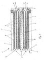
- Fig. 1 shows an additional electric heater in the form of a Wienblokkes 1, which can be installed in a heating or air conditioning for a motor vehicle.
- This heating block 1 is used to heat air, which is supplied to the vehicle interior.
- the heating block 1 consists of a frame or mounting frame 2, which has two longitudinal bars 3, 4 and two transverse bars 5, 6. Parallel to the longitudinal beams 3, 4 rod-shaped heating elements 7 are arranged alternately with corrugated fins 8.
- a metallic, ie electrically conductive spring element 9 is arranged, which exerts on the two adjacent heating elements 7 a uniformly distributed over the length of spring force in the direction of the longitudinal bars 3, 4.
- One half of the total of six heating elements 7, the detailed structure of which is described in detail below, has connection contacts 10 which are connected to positive plugs 11.
- the other half of the heating elements 7 has on the opposite side of the positive plugs 11 connecting contacts 12 which are connected via a terminal 13 and a sheet metal screw 14 with the negative pole formed as a cross member 6, wherein the cross member 6 is connected to ground in the vehicle.
- the electrical connection of the heating elements 7 is similar to that in the earlier European Application No. 02 292 464.1, d. H. the Heating elements 7 are alternately connected to plus and minus, so that the current from one heating element 7 to the next about the corrugated fins 8 flows.
- this heating block 1 in a not shown Air duct of a heating system to be installed, so that the air through the Corrugated ribs 8 flows while being heated.
- the corrugated ribs 8 thus lead the heat generated in the heating elements 7 from the air and therefore act as secondary surface elements for enlarging the heat transfer surface. This ensures effective and rapid heating of the air.
- the heating block 1 can at any point in the not shown Air flow channel or directly to a not shown Radiator of the heating system to be mounted.
- Fig. 2 shows a heating element 7 as a single part in a view from the side, ie with a view of a narrow side 7a.
- the heating element has two electrodes 15, 16, wherein an electrode 15 has the connection contact 10 (see Fig. 1).
- the other electrode 16 has no Anschuss Quilt on.
- FIG. 3 shows the heating element 7 in a plan view, ie with a view of a broad side 7b, which is formed by the continuous electrode 15 with the connection contact 10.
- Fig. 4 shows a cross section along the line IV-IV in Fig. 3 by the heating element 7.
- the plastic layer 18 in conjunction with the two beads 18a, 18b therefore forms a mechanical connection for the two contact sheets 15, 16, which may otherwise have a special structure or roughening to improve the electrical and thermal conductivity.
- the heating element 7 is extremely easy to produce by injection molding in that the two contact plates 15, 16 are positioned in an injection mold and then encapsulated with the plastic.
- the outer surfaces of the contact elements 15, 16 remain free, so that there is a good thermal and electrical contact with the corrugated fins 8, not shown here.
Landscapes
- Engineering & Computer Science (AREA)
- Physics & Mathematics (AREA)
- Thermal Sciences (AREA)
- Mechanical Engineering (AREA)
- Chemical & Material Sciences (AREA)
- Combustion & Propulsion (AREA)
- General Engineering & Computer Science (AREA)
- Air-Conditioning For Vehicles (AREA)
- Resistance Heating (AREA)
- Direct Air Heating By Heater Or Combustion Gas (AREA)
Abstract
- mit einem geschlossenen Rahmen (2), bestehend aus Längsholmen (3, 4) und Querholmen (5, 6),
- mit Heizelementen (7), bestehend aus zwischen Kontaktblechen (15, 16) angeordneten, elektrisch leitenden Kunststoffschichten (18) mit PTC-Effekt,
- mit wärmeleitenden, von Luft überströmbaren Sekundärflächenelementen (8) und
- mit mindestens einem elektrisch leitenden Federelement (9),
- wobei die Heizelemente (7) und die Sekundärflächenelemente (8) abwechselnd nebeneinander angeordnet und gegeneinander über die Längsholme (3, 4) und das mittig an Stelle eines Sekundärflächenelementes (8) angeordnete Federelement (9) verspannt sind.
Description
- Fig. 1
- eine elektrische Zusatzheizung in Form eines Heizblockes,
- Fig. 2
- ein Heizelement des Heizblockes gemäß Fig. 1 in einer Seitenansicht,
- Fig. 3
- das Heizelement gemäß Fig. 2 in einer Draufsicht und
- Fig. 4
- einen Schnitt längs der Linie IV-IV in Fig. 3 in vergrößerter Darstellung.
Claims (10)
- Elektrische Heizeinrichtung, insbesondere für ein Kraftfahrzeugmit einem geschlossenen Rahmen (2), bestehend aus Längsholmen (3, 4) und Querholmen (5, 6),mit Heizelementen (7), bestehend aus zwischen Kontaktblechen (15, 16) angeordneten, elektrisch leitenden Kunststoffschichten (18) mit PTC-Effekt,mit wärmeleitenden, von Luft überströmbaren Sekundärflächenelementen (8) undmit mindestens einem elektrisch leitenden Federelement (9),wobei die Heizelemente (7) und die Sekundärflächenelemente (8) abwechselnd nebeneinander angeordnet und gegeneinander über die Längsholme (3, 4) und das mittig an Stelle eines Sekundärflächenelementes (8) angeordnete Federelement (9) verspannt sind.
- Heizeinrichtung nach Anspruch 1, dadurch gekennzeichnet, dass die Heizelemente als Heizstäbe (7) und die Kontaktbleche als parallel zueinander angeordnete Blechstreifen (15,1 6) ausgebildet sind.
- Heizeinrichtung nach Anspruch 1 oder 2, dadurch gekennzeichnet, dass die Kontaktbleche (15, 16) vom Kunststoff (18a, 18b) teilweise umspritzt sind.
- Heizeinrichtung nach Anspruch 1, 2 oder 3, dadurch gekennzeichnet, dass die Sekundärflächenelemente als Wellrippen (8) ausgebildet sind, die in metallischer Verbindung mit den Kontaktblechen (15, 16) stehen.
- Heizeinrichtung nach einem der Ansprüche 1 bis 4, dadurch gekennzeichnet, dass das Federelement als luftdurchlässige Metallfeder (9) ausgebildet ist.
- Heizeinrichtung nach einem der Ansprüche 2 bis 5, dadurch gekennzeichnet, dass das Kontaktblech (15) entweder als Plus-Elektrode mit einem Plus-Anschlusskontakt (10) oder als Minus-Elektrode mit einem Minus-Anschlusskontakt (12) ausgebildet ist und dass die Plus-Anschlusskontakte (10) mit Plussteckern (11) und die Minus-Anschlusskontakte (12) mit einer Minusschiene (6) verbunden sind.
- Heizeinrichtung nach Anspruch 6, dadurch gekennzeichnet, dass die Plusstecker (11) an dem Querholm (5) angeordnet sind und die Minusschiene durch den Querholm (6) gebildet ist.
- Heizeinrichtung nach einem der Ansprüche 1 bis 7, dadurch gekennzeichnet, dass der Kunststoff ein PP, PE, EVA, PA mit leitenden Partikeln, insbesondere Leitruß ist.
- Heizeinrichtung nach einem der Ansprüche 1 bis 8, dadurch gekennzeichnet, dass die Kunststoffschicht (18) zwischen den Kontaktblechen (15, 16) eine Dicke s im Bereich von 1 bis 2 mm aufweist.
- Heizeinrichtung nach einem der Ansprüche 1 bis 9, dadurch gekennzeichnet, dass die Heizelemente (7) Schmalseiten (7a) aufweisen und dass die Kontaktbleche (15, 16) im Bereich der Schmalseinen (7a) vom Kunststoff derart umspritzt sind, dass beiderseits Wulste (18a, 18b) gebildet sind, die eine mechanische Verbindung zwischen den Kontaktblechen (15, 16) bilden.
Priority Applications (6)
| Application Number | Priority Date | Filing Date | Title |
|---|---|---|---|
| DE50309125T DE50309125D1 (de) | 2003-03-13 | 2003-03-13 | Elektrische Heizeinrichtung, insbesondere für ein Kraftfahrzeug |
| AT03005697T ATE385470T1 (de) | 2003-03-13 | 2003-03-13 | Elektrische heizeinrichtung, insbesondere für ein kraftfahrzeug |
| ES03005697T ES2300511T3 (es) | 2003-03-13 | 2003-03-13 | Dispositivo de calefaccion electrico, en particular para un automovil. |
| EP03005697A EP1457367B1 (de) | 2003-03-13 | 2003-03-13 | Elektrische Heizeinrichtung, insbesondere für ein Kraftfahrzeug |
| PCT/EP2004/002296 WO2004080738A1 (de) | 2003-03-13 | 2004-03-05 | Elektrische heizeinrichtung, insbesondere für kraftfahrzeuge |
| US10/548,734 US7361868B2 (en) | 2003-03-13 | 2004-03-05 | Electrical heating device, especially for motor vehicles |
Applications Claiming Priority (1)
| Application Number | Priority Date | Filing Date | Title |
|---|---|---|---|
| EP03005697A EP1457367B1 (de) | 2003-03-13 | 2003-03-13 | Elektrische Heizeinrichtung, insbesondere für ein Kraftfahrzeug |
Publications (2)
| Publication Number | Publication Date |
|---|---|
| EP1457367A1 true EP1457367A1 (de) | 2004-09-15 |
| EP1457367B1 EP1457367B1 (de) | 2008-02-06 |
Family
ID=32748879
Family Applications (1)
| Application Number | Title | Priority Date | Filing Date |
|---|---|---|---|
| EP03005697A Expired - Lifetime EP1457367B1 (de) | 2003-03-13 | 2003-03-13 | Elektrische Heizeinrichtung, insbesondere für ein Kraftfahrzeug |
Country Status (6)
| Country | Link |
|---|---|
| US (1) | US7361868B2 (de) |
| EP (1) | EP1457367B1 (de) |
| AT (1) | ATE385470T1 (de) |
| DE (1) | DE50309125D1 (de) |
| ES (1) | ES2300511T3 (de) |
| WO (1) | WO2004080738A1 (de) |
Cited By (3)
| Publication number | Priority date | Publication date | Assignee | Title |
|---|---|---|---|---|
| EP1731340A1 (de) * | 2005-06-07 | 2006-12-13 | Catem GmbH & Co. KG | Elektrische Heizeinrichtung |
| KR101310111B1 (ko) * | 2005-09-23 | 2013-09-24 | 에베르쉬페쳐 카템 게엠베하 운트 캄파니 카게 | 난방 장치의 열 생성 부재 |
| WO2018215545A1 (de) * | 2017-05-24 | 2018-11-29 | Webasto SE | Elektrisches heizgerät |
Families Citing this family (13)
| Publication number | Priority date | Publication date | Assignee | Title |
|---|---|---|---|---|
| EP1467599B1 (de) * | 2003-04-12 | 2008-11-26 | Eichenauer Heizelemente GmbH & Co.KG | Vorrichtung zur Aufnahme von Keramik-Heizelementen und Verfahren zur Herstellung einer solchen |
| DE102005030392A1 (de) * | 2005-06-29 | 2007-01-04 | BSH Bosch und Siemens Hausgeräte GmbH | Hausgerät sowie Garguträger-Haltevorrichtung für ein Hausgerät |
| US7576305B2 (en) * | 2006-09-22 | 2009-08-18 | Catem Gmbh & Co. Kg | Heat-generating element of a heating device |
| EP2017103B1 (de) * | 2007-07-18 | 2016-05-04 | Eberspächer catem GmbH & Co. KG | Elektrische Heizvorrichtung |
| EP2017546B1 (de) * | 2007-07-18 | 2016-04-13 | Eberspächer catem GmbH & Co. KG | Verfahren zum Herstellen einer elektrischen Heizvorrichtung sowie elektrischer Heizvorrichtungen |
| US7723652B2 (en) * | 2007-08-16 | 2010-05-25 | Shu-Lien Chen | Adjusting device for adjusting tension of heating straps on heating assembly |
| US8057946B2 (en) * | 2008-03-24 | 2011-11-15 | GM Global Technology Operations LLC | Integrated charge air heat exchanger |
| DE102012109801B4 (de) * | 2012-10-15 | 2015-02-05 | Borgwarner Ludwigsburg Gmbh | Elektrische Heizvorrichtung |
| JP2016002998A (ja) * | 2014-06-19 | 2016-01-12 | 現代自動車株式会社Hyundaimotor Company | 車両用ハイブリッドヒーター |
| US10183553B2 (en) * | 2014-08-13 | 2019-01-22 | Surface Igniter Llc | Heating system for a motor vehicle |
| CN106382739A (zh) * | 2015-07-26 | 2017-02-08 | 谢彦君 | 一种电制热器 |
| US10774802B2 (en) | 2017-05-15 | 2020-09-15 | Phillips & Temro Industries Inc. | Intake air heating system for a vehicle |
| DE102018101453A1 (de) * | 2018-01-23 | 2019-07-25 | Borgwarner Ludwigsburg Gmbh | Heizvorrichtung und Verfahren zum Herstellung eines Heizstabes |
Citations (8)
| Publication number | Priority date | Publication date | Assignee | Title |
|---|---|---|---|---|
| EP0092406A2 (de) * | 1982-04-16 | 1983-10-26 | RAYCHEM CORPORATION (a Delaware corporation) | Langgestreckte elektrische Heizvorrichtung und Einrichtung mit solchen Vorrichtungen |
| US4425497A (en) * | 1979-08-17 | 1984-01-10 | Raychem Corporation | PTC Heater assembly |
| US4833305A (en) * | 1986-08-12 | 1989-05-23 | Mitsuboshi Belting Limited | Thermally self-regulating elastomeric composition and heating element utilizing such composition |
| US5206476A (en) | 1991-09-30 | 1993-04-27 | General Motors Corporation | Supplementary automobile duct heater |
| DE4213510C1 (en) | 1992-04-24 | 1993-08-19 | Audi Ag, 8070 Ingolstadt, De | Electric heating arrangement in vehicle heating and ventilation system - is formed by grill located in air outlet and moulded in conductive polymer |
| DE19911547A1 (de) | 1999-03-16 | 2000-09-21 | Behr Gmbh & Co | Elektrische Heizeinrichtung für ein Kraftfahrzeug |
| DE19957452A1 (de) | 1999-11-19 | 2001-05-23 | Behr France Sarl | Elektrische Heizeinrichtung, insbesondere für ein Kraftfahrzeug |
| EP1130337A2 (de) * | 2000-02-17 | 2001-09-05 | ELTEK S.p.A. | Elektrischem Heizkörper |
Family Cites Families (5)
| Publication number | Priority date | Publication date | Assignee | Title |
|---|---|---|---|---|
| US4761541A (en) * | 1984-01-23 | 1988-08-02 | Raychem Corporation | Devices comprising conductive polymer compositions |
| DE3873414T2 (de) | 1987-05-12 | 1993-02-04 | Diamant Boart Stratabit Sa | Schraubverbindung fuer bohrgestaenge. |
| JPH0261976A (ja) * | 1988-08-26 | 1990-03-01 | Murata Mfg Co Ltd | 面状発熱体 |
| DE4434613A1 (de) * | 1994-09-28 | 1996-04-04 | Behr Gmbh & Co | Elektrische Heizeinrichtung, insbesondere für ein Kraftfahrzeug |
| ES2236991T3 (es) * | 1999-06-15 | 2005-07-16 | DAVID & BAADER DBK SPEZIALFABRIK ELEKTRISCHER APPARATE UND HEIZWIDERSTANDE GMBH | Dispositivo de calefaccion destinado para el calentamiento de aire. |
-
2003
- 2003-03-13 AT AT03005697T patent/ATE385470T1/de not_active IP Right Cessation
- 2003-03-13 DE DE50309125T patent/DE50309125D1/de not_active Expired - Lifetime
- 2003-03-13 EP EP03005697A patent/EP1457367B1/de not_active Expired - Lifetime
- 2003-03-13 ES ES03005697T patent/ES2300511T3/es not_active Expired - Lifetime
-
2004
- 2004-03-05 WO PCT/EP2004/002296 patent/WO2004080738A1/de active Application Filing
- 2004-03-05 US US10/548,734 patent/US7361868B2/en not_active Expired - Lifetime
Patent Citations (8)
| Publication number | Priority date | Publication date | Assignee | Title |
|---|---|---|---|---|
| US4425497A (en) * | 1979-08-17 | 1984-01-10 | Raychem Corporation | PTC Heater assembly |
| EP0092406A2 (de) * | 1982-04-16 | 1983-10-26 | RAYCHEM CORPORATION (a Delaware corporation) | Langgestreckte elektrische Heizvorrichtung und Einrichtung mit solchen Vorrichtungen |
| US4833305A (en) * | 1986-08-12 | 1989-05-23 | Mitsuboshi Belting Limited | Thermally self-regulating elastomeric composition and heating element utilizing such composition |
| US5206476A (en) | 1991-09-30 | 1993-04-27 | General Motors Corporation | Supplementary automobile duct heater |
| DE4213510C1 (en) | 1992-04-24 | 1993-08-19 | Audi Ag, 8070 Ingolstadt, De | Electric heating arrangement in vehicle heating and ventilation system - is formed by grill located in air outlet and moulded in conductive polymer |
| DE19911547A1 (de) | 1999-03-16 | 2000-09-21 | Behr Gmbh & Co | Elektrische Heizeinrichtung für ein Kraftfahrzeug |
| DE19957452A1 (de) | 1999-11-19 | 2001-05-23 | Behr France Sarl | Elektrische Heizeinrichtung, insbesondere für ein Kraftfahrzeug |
| EP1130337A2 (de) * | 2000-02-17 | 2001-09-05 | ELTEK S.p.A. | Elektrischem Heizkörper |
Cited By (5)
| Publication number | Priority date | Publication date | Assignee | Title |
|---|---|---|---|---|
| EP1731340A1 (de) * | 2005-06-07 | 2006-12-13 | Catem GmbH & Co. KG | Elektrische Heizeinrichtung |
| KR101310111B1 (ko) * | 2005-09-23 | 2013-09-24 | 에베르쉬페쳐 카템 게엠베하 운트 캄파니 카게 | 난방 장치의 열 생성 부재 |
| WO2018215545A1 (de) * | 2017-05-24 | 2018-11-29 | Webasto SE | Elektrisches heizgerät |
| CN110678705A (zh) * | 2017-05-24 | 2020-01-10 | 韦巴斯托股份公司 | 用于行驶工具的空气加热器 |
| CN110678343A (zh) * | 2017-05-24 | 2020-01-10 | 韦巴斯托股份公司 | 电加热器 |
Also Published As
| Publication number | Publication date |
|---|---|
| ATE385470T1 (de) | 2008-02-15 |
| DE50309125D1 (de) | 2008-03-20 |
| US20070045263A1 (en) | 2007-03-01 |
| WO2004080738A1 (de) | 2004-09-23 |
| ES2300511T3 (es) | 2008-06-16 |
| US7361868B2 (en) | 2008-04-22 |
| EP1457367B1 (de) | 2008-02-06 |
Similar Documents
| Publication | Publication Date | Title |
|---|---|---|
| EP1457367B1 (de) | Elektrische Heizeinrichtung, insbesondere für ein Kraftfahrzeug | |
| EP1916873B1 (de) | Wärmeerzeugendes Element für eine elektrische Heizvorrichtung und Verfahren zur Herstellung derselben | |
| EP2608632B1 (de) | Elektrische Heizvorrichtung und Rahmen hierfür | |
| DE112007001364B4 (de) | Halbleitereinrichtung und elektrische Einrichtung mit einer derartigen Halbleitereinrichtung | |
| EP2211590B1 (de) | Wärmeübertrager | |
| DE102006018784A1 (de) | Elektrische Heizvorrichtung, insbesondere für Automobile | |
| DE102009039099A1 (de) | Positiver Temperaturkoeffizient (PTC)-Stabvorrichtung | |
| DE102019208130A1 (de) | PTC-Heizelement und eine elektrische Heizvorrichtung | |
| WO2010003900A1 (de) | Heizungsvorrichtung und verfahren zur herstellung der heizungsvorrichtung | |
| EP2145783B1 (de) | Fahrzeugheizung | |
| EP1926346A1 (de) | Elektrische Heizungsvorrichtung, insbesondere für ein Kraftfahrzeug | |
| DE102010048593A1 (de) | Modulare Heizvorrichtung | |
| EP2145782B1 (de) | Fahrzeugheizung | |
| DE102019217453A1 (de) | PTC-Heizzelle | |
| EP2346304B1 (de) | Wärmeübertrager | |
| EP1522439B2 (de) | Heizungsanordnung mit PTC-Element, insbesondere für ein Kraftfahrzeug | |
| DE102007062302A1 (de) | Heizvorrichtung | |
| DE112006001282T5 (de) | Vorwärmer für ein Fahrzeug | |
| DE19804496A1 (de) | Elektrisches Widerstandsheizelement mit einem Wabenkörper aus Widerstandsmaterial mit positivem Temperaturkoeffizienten des Widerstandes (PTC-Widerstand) | |
| DE69100740T2 (de) | Luftheizungsgerät und Heizungszusammenbau. | |
| EP1523225B1 (de) | Heizungsanordnung mit PTC-Element, insbesondere für ein Kraftfahrzeug | |
| DE7626535U1 (de) | Heizkoerper fuer einen elektrischen heizungskonvektor | |
| DE102018207037A1 (de) | Elektrische Heizeinrichtung mit einem eine Rippenstruktur aufweisenden Kühlkörper | |
| EP2540540A1 (de) | Heizkörper mit integrierter elektrischer Zusatzheizung | |
| EP3557155A1 (de) | Elektrische heizvorrichtung |
Legal Events
| Date | Code | Title | Description |
|---|---|---|---|
| PUAI | Public reference made under article 153(3) epc to a published international application that has entered the european phase |
Free format text: ORIGINAL CODE: 0009012 |
|
| AK | Designated contracting states |
Kind code of ref document: A1 Designated state(s): AT BE BG CH CY CZ DE DK EE ES FI FR GB GR HU IE IT LI LU MC NL PT RO SE SI SK TR |
|
| AX | Request for extension of the european patent |
Extension state: AL LT LV MK |
|
| RAP1 | Party data changed (applicant data changed or rights of an application transferred) |
Owner name: BEHR GMBH & CO. KG Owner name: BEHR FRANCE S.A.R.L. |
|
| 17P | Request for examination filed |
Effective date: 20050315 |
|
| AKX | Designation fees paid |
Designated state(s): AT BE BG CH CY CZ DE DK EE ES FI FR GB GR HU IE IT LI LU MC NL PT RO SE SI SK TR |
|
| RAP1 | Party data changed (applicant data changed or rights of an application transferred) |
Owner name: BEHR GMBH & CO. KG Owner name: BEHR FRANCE ROUFFACH SAS |
|
| 17Q | First examination report despatched |
Effective date: 20061109 |
|
| GRAP | Despatch of communication of intention to grant a patent |
Free format text: ORIGINAL CODE: EPIDOSNIGR1 |
|
| GRAS | Grant fee paid |
Free format text: ORIGINAL CODE: EPIDOSNIGR3 |
|
| GRAA | (expected) grant |
Free format text: ORIGINAL CODE: 0009210 |
|
| AK | Designated contracting states |
Kind code of ref document: B1 Designated state(s): AT BE BG CH CY CZ DE DK EE ES FI FR GB GR HU IE IT LI LU MC NL PT RO SE SI SK TR |
|
| REG | Reference to a national code |
Ref country code: GB Ref legal event code: FG4D Free format text: NOT ENGLISH |
|
| REG | Reference to a national code |
Ref country code: CH Ref legal event code: EP |
|
| REG | Reference to a national code |
Ref country code: IE Ref legal event code: FG4D Free format text: LANGUAGE OF EP DOCUMENT: GERMAN |
|
| REF | Corresponds to: |
Ref document number: 50309125 Country of ref document: DE Date of ref document: 20080320 Kind code of ref document: P |
|
| REG | Reference to a national code |
Ref country code: ES Ref legal event code: FG2A Ref document number: 2300511 Country of ref document: ES Kind code of ref document: T3 |
|
| PG25 | Lapsed in a contracting state [announced via postgrant information from national office to epo] |
Ref country code: FI Free format text: LAPSE BECAUSE OF FAILURE TO SUBMIT A TRANSLATION OF THE DESCRIPTION OR TO PAY THE FEE WITHIN THE PRESCRIBED TIME-LIMIT Effective date: 20080206 |
|
| NLV1 | Nl: lapsed or annulled due to failure to fulfill the requirements of art. 29p and 29m of the patents act | ||
| BERE | Be: lapsed |
Owner name: BEHR FRANCE ROUFFACH SAS Effective date: 20080331 Owner name: BEHR G.M.B.H. & CO. KG Effective date: 20080331 |
|
| PG25 | Lapsed in a contracting state [announced via postgrant information from national office to epo] |
Ref country code: SI Free format text: LAPSE BECAUSE OF FAILURE TO SUBMIT A TRANSLATION OF THE DESCRIPTION OR TO PAY THE FEE WITHIN THE PRESCRIBED TIME-LIMIT Effective date: 20080206 |
|
| PGFP | Annual fee paid to national office [announced via postgrant information from national office to epo] |
Ref country code: IT Payment date: 20080418 Year of fee payment: 6 |
|
| REG | Reference to a national code |
Ref country code: IE Ref legal event code: FD4D |
|
| ET | Fr: translation filed | ||
| PG25 | Lapsed in a contracting state [announced via postgrant information from national office to epo] |
Ref country code: IE Free format text: LAPSE BECAUSE OF FAILURE TO SUBMIT A TRANSLATION OF THE DESCRIPTION OR TO PAY THE FEE WITHIN THE PRESCRIBED TIME-LIMIT Effective date: 20080206 Ref country code: NL Free format text: LAPSE BECAUSE OF FAILURE TO SUBMIT A TRANSLATION OF THE DESCRIPTION OR TO PAY THE FEE WITHIN THE PRESCRIBED TIME-LIMIT Effective date: 20080206 Ref country code: CZ Free format text: LAPSE BECAUSE OF FAILURE TO SUBMIT A TRANSLATION OF THE DESCRIPTION OR TO PAY THE FEE WITHIN THE PRESCRIBED TIME-LIMIT Effective date: 20080206 Ref country code: MC Free format text: LAPSE BECAUSE OF NON-PAYMENT OF DUE FEES Effective date: 20080331 Ref country code: SE Free format text: LAPSE BECAUSE OF FAILURE TO SUBMIT A TRANSLATION OF THE DESCRIPTION OR TO PAY THE FEE WITHIN THE PRESCRIBED TIME-LIMIT Effective date: 20080506 Ref country code: SK Free format text: LAPSE BECAUSE OF FAILURE TO SUBMIT A TRANSLATION OF THE DESCRIPTION OR TO PAY THE FEE WITHIN THE PRESCRIBED TIME-LIMIT Effective date: 20080206 Ref country code: DK Free format text: LAPSE BECAUSE OF FAILURE TO SUBMIT A TRANSLATION OF THE DESCRIPTION OR TO PAY THE FEE WITHIN THE PRESCRIBED TIME-LIMIT Effective date: 20080206 Ref country code: PT Free format text: LAPSE BECAUSE OF FAILURE TO SUBMIT A TRANSLATION OF THE DESCRIPTION OR TO PAY THE FEE WITHIN THE PRESCRIBED TIME-LIMIT Effective date: 20080707 |
|
| REG | Reference to a national code |
Ref country code: CH Ref legal event code: PL |
|
| PLBI | Opposition filed |
Free format text: ORIGINAL CODE: 0009260 |
|
| PG25 | Lapsed in a contracting state [announced via postgrant information from national office to epo] |
Ref country code: RO Free format text: LAPSE BECAUSE OF FAILURE TO SUBMIT A TRANSLATION OF THE DESCRIPTION OR TO PAY THE FEE WITHIN THE PRESCRIBED TIME-LIMIT Effective date: 20080206 |
|
| PLAX | Notice of opposition and request to file observation + time limit sent |
Free format text: ORIGINAL CODE: EPIDOSNOBS2 |
|
| 26 | Opposition filed |
Opponent name: BERU AG Effective date: 20081106 |
|
| GBPC | Gb: european patent ceased through non-payment of renewal fee |
Effective date: 20080506 |
|
| PG25 | Lapsed in a contracting state [announced via postgrant information from national office to epo] |
Ref country code: LI Free format text: LAPSE BECAUSE OF NON-PAYMENT OF DUE FEES Effective date: 20080331 Ref country code: CH Free format text: LAPSE BECAUSE OF NON-PAYMENT OF DUE FEES Effective date: 20080331 Ref country code: EE Free format text: LAPSE BECAUSE OF FAILURE TO SUBMIT A TRANSLATION OF THE DESCRIPTION OR TO PAY THE FEE WITHIN THE PRESCRIBED TIME-LIMIT Effective date: 20080206 |
|
| PG25 | Lapsed in a contracting state [announced via postgrant information from national office to epo] |
Ref country code: BE Free format text: LAPSE BECAUSE OF NON-PAYMENT OF DUE FEES Effective date: 20080331 |
|
| PLAF | Information modified related to communication of a notice of opposition and request to file observations + time limit |
Free format text: ORIGINAL CODE: EPIDOSCOBS2 |
|
| PG25 | Lapsed in a contracting state [announced via postgrant information from national office to epo] |
Ref country code: BG Free format text: LAPSE BECAUSE OF FAILURE TO SUBMIT A TRANSLATION OF THE DESCRIPTION OR TO PAY THE FEE WITHIN THE PRESCRIBED TIME-LIMIT Effective date: 20080506 |
|
| PG25 | Lapsed in a contracting state [announced via postgrant information from national office to epo] |
Ref country code: GB Free format text: LAPSE BECAUSE OF NON-PAYMENT OF DUE FEES Effective date: 20080506 |
|
| PG25 | Lapsed in a contracting state [announced via postgrant information from national office to epo] |
Ref country code: CY Free format text: LAPSE BECAUSE OF FAILURE TO SUBMIT A TRANSLATION OF THE DESCRIPTION OR TO PAY THE FEE WITHIN THE PRESCRIBED TIME-LIMIT Effective date: 20080206 |
|
| PLAB | Opposition data, opponent's data or that of the opponent's representative modified |
Free format text: ORIGINAL CODE: 0009299OPPO |
|
| PG25 | Lapsed in a contracting state [announced via postgrant information from national office to epo] |
Ref country code: AT Free format text: LAPSE BECAUSE OF NON-PAYMENT OF DUE FEES Effective date: 20080313 |
|
| R26 | Opposition filed (corrected) |
Opponent name: BERU AG Effective date: 20081106 |
|
| PLCK | Communication despatched that opposition was rejected |
Free format text: ORIGINAL CODE: EPIDOSNREJ1 |
|
| PGFP | Annual fee paid to national office [announced via postgrant information from national office to epo] |
Ref country code: ES Payment date: 20100326 Year of fee payment: 8 |
|
| PLBN | Opposition rejected |
Free format text: ORIGINAL CODE: 0009273 |
|
| STAA | Information on the status of an ep patent application or granted ep patent |
Free format text: STATUS: OPPOSITION REJECTED |
|
| 27O | Opposition rejected |
Effective date: 20100201 |
|
| PG25 | Lapsed in a contracting state [announced via postgrant information from national office to epo] |
Ref country code: HU Free format text: LAPSE BECAUSE OF FAILURE TO SUBMIT A TRANSLATION OF THE DESCRIPTION OR TO PAY THE FEE WITHIN THE PRESCRIBED TIME-LIMIT Effective date: 20080807 Ref country code: LU Free format text: LAPSE BECAUSE OF NON-PAYMENT OF DUE FEES Effective date: 20080313 |
|
| PG25 | Lapsed in a contracting state [announced via postgrant information from national office to epo] |
Ref country code: TR Free format text: LAPSE BECAUSE OF FAILURE TO SUBMIT A TRANSLATION OF THE DESCRIPTION OR TO PAY THE FEE WITHIN THE PRESCRIBED TIME-LIMIT Effective date: 20080206 |
|
| PG25 | Lapsed in a contracting state [announced via postgrant information from national office to epo] |
Ref country code: GR Free format text: LAPSE BECAUSE OF FAILURE TO SUBMIT A TRANSLATION OF THE DESCRIPTION OR TO PAY THE FEE WITHIN THE PRESCRIBED TIME-LIMIT Effective date: 20080507 |
|
| PG25 | Lapsed in a contracting state [announced via postgrant information from national office to epo] |
Ref country code: IT Free format text: LAPSE BECAUSE OF NON-PAYMENT OF DUE FEES Effective date: 20090313 |
|
| REG | Reference to a national code |
Ref country code: ES Ref legal event code: FD2A Effective date: 20120509 |
|
| PG25 | Lapsed in a contracting state [announced via postgrant information from national office to epo] |
Ref country code: ES Free format text: LAPSE BECAUSE OF NON-PAYMENT OF DUE FEES Effective date: 20110314 |
|
| REG | Reference to a national code |
Ref country code: DE Ref legal event code: R082 Ref document number: 50309125 Country of ref document: DE Representative=s name: GRAUEL, ANDREAS, DIPL.-PHYS. DR. RER. NAT., DE Ref country code: DE Ref legal event code: R081 Ref document number: 50309125 Country of ref document: DE Owner name: MAHLE INTERNATIONAL GMBH, DE Free format text: FORMER OWNERS: BEHR GMBH & CO. KG, 70469 STUTTGART, DE; BEHR FRANCE ROUFFACH S.A.S., ROUFFACH, FR |
|
| REG | Reference to a national code |
Ref country code: FR Ref legal event code: PLFP Year of fee payment: 14 |
|
| REG | Reference to a national code |
Ref country code: FR Ref legal event code: PLFP Year of fee payment: 15 |
|
| REG | Reference to a national code |
Ref country code: FR Ref legal event code: PLFP Year of fee payment: 16 |
|
| PGFP | Annual fee paid to national office [announced via postgrant information from national office to epo] |
Ref country code: FR Payment date: 20190322 Year of fee payment: 17 |
|
| PGFP | Annual fee paid to national office [announced via postgrant information from national office to epo] |
Ref country code: DE Payment date: 20190404 Year of fee payment: 17 |
|
| REG | Reference to a national code |
Ref country code: DE Ref legal event code: R119 Ref document number: 50309125 Country of ref document: DE |
|
| PG25 | Lapsed in a contracting state [announced via postgrant information from national office to epo] |
Ref country code: FR Free format text: LAPSE BECAUSE OF NON-PAYMENT OF DUE FEES Effective date: 20200331 Ref country code: DE Free format text: LAPSE BECAUSE OF NON-PAYMENT OF DUE FEES Effective date: 20201001 |