EP1454048B1 - Procede d'arret et de redemarrage d'un moteur a combustion interne a injection indirecte - Google Patents
Procede d'arret et de redemarrage d'un moteur a combustion interne a injection indirecte Download PDFInfo
- Publication number
- EP1454048B1 EP1454048B1 EP02772462A EP02772462A EP1454048B1 EP 1454048 B1 EP1454048 B1 EP 1454048B1 EP 02772462 A EP02772462 A EP 02772462A EP 02772462 A EP02772462 A EP 02772462A EP 1454048 B1 EP1454048 B1 EP 1454048B1
- Authority
- EP
- European Patent Office
- Prior art keywords
- engine
- cylinder
- ignition
- stopping
- rotating part
- Prior art date
- Legal status (The legal status is an assumption and is not a legal conclusion. Google has not performed a legal analysis and makes no representation as to the accuracy of the status listed.)
- Expired - Lifetime
Links
Images

Classifications
-
- F—MECHANICAL ENGINEERING; LIGHTING; HEATING; WEAPONS; BLASTING
- F02—COMBUSTION ENGINES; HOT-GAS OR COMBUSTION-PRODUCT ENGINE PLANTS
- F02N—STARTING OF COMBUSTION ENGINES; STARTING AIDS FOR SUCH ENGINES, NOT OTHERWISE PROVIDED FOR
- F02N99/00—Subject matter not provided for in the other groups of this subclass
- F02N99/002—Starting combustion engines by ignition means
- F02N99/006—Providing a combustible mixture inside the cylinder
-
- F—MECHANICAL ENGINEERING; LIGHTING; HEATING; WEAPONS; BLASTING
- F02—COMBUSTION ENGINES; HOT-GAS OR COMBUSTION-PRODUCT ENGINE PLANTS
- F02D—CONTROLLING COMBUSTION ENGINES
- F02D41/00—Electrical control of supply of combustible mixture or its constituents
- F02D41/02—Circuit arrangements for generating control signals
- F02D41/04—Introducing corrections for particular operating conditions
- F02D41/06—Introducing corrections for particular operating conditions for engine starting or warming up
-
- F—MECHANICAL ENGINEERING; LIGHTING; HEATING; WEAPONS; BLASTING
- F02—COMBUSTION ENGINES; HOT-GAS OR COMBUSTION-PRODUCT ENGINE PLANTS
- F02D—CONTROLLING COMBUSTION ENGINES
- F02D41/00—Electrical control of supply of combustible mixture or its constituents
- F02D41/02—Circuit arrangements for generating control signals
- F02D41/04—Introducing corrections for particular operating conditions
- F02D41/042—Introducing corrections for particular operating conditions for stopping the engine
-
- F—MECHANICAL ENGINEERING; LIGHTING; HEATING; WEAPONS; BLASTING
- F02—COMBUSTION ENGINES; HOT-GAS OR COMBUSTION-PRODUCT ENGINE PLANTS
- F02D—CONTROLLING COMBUSTION ENGINES
- F02D41/00—Electrical control of supply of combustible mixture or its constituents
- F02D41/02—Circuit arrangements for generating control signals
- F02D41/04—Introducing corrections for particular operating conditions
- F02D41/06—Introducing corrections for particular operating conditions for engine starting or warming up
- F02D41/062—Introducing corrections for particular operating conditions for engine starting or warming up for starting
-
- F—MECHANICAL ENGINEERING; LIGHTING; HEATING; WEAPONS; BLASTING
- F02—COMBUSTION ENGINES; HOT-GAS OR COMBUSTION-PRODUCT ENGINE PLANTS
- F02N—STARTING OF COMBUSTION ENGINES; STARTING AIDS FOR SUCH ENGINES, NOT OTHERWISE PROVIDED FOR
- F02N11/00—Starting of engines by means of electric motors
- F02N11/08—Circuits specially adapted for starting of engines
- F02N11/0814—Circuits specially adapted for starting of engines comprising means for controlling automatic idle-start-stop
-
- F—MECHANICAL ENGINEERING; LIGHTING; HEATING; WEAPONS; BLASTING
- F02—COMBUSTION ENGINES; HOT-GAS OR COMBUSTION-PRODUCT ENGINE PLANTS
- F02D—CONTROLLING COMBUSTION ENGINES
- F02D41/00—Electrical control of supply of combustible mixture or its constituents
- F02D41/009—Electrical control of supply of combustible mixture or its constituents using means for generating position or synchronisation signals
- F02D2041/0095—Synchronisation of the cylinders during engine shutdown
-
- F—MECHANICAL ENGINEERING; LIGHTING; HEATING; WEAPONS; BLASTING
- F02—COMBUSTION ENGINES; HOT-GAS OR COMBUSTION-PRODUCT ENGINE PLANTS
- F02N—STARTING OF COMBUSTION ENGINES; STARTING AIDS FOR SUCH ENGINES, NOT OTHERWISE PROVIDED FOR
- F02N19/00—Starting aids for combustion engines, not otherwise provided for
- F02N19/005—Aiding engine start by starting from a predetermined position, e.g. pre-positioning or reverse rotation
- F02N2019/008—Aiding engine start by starting from a predetermined position, e.g. pre-positioning or reverse rotation the engine being stopped in a particular position
-
- F—MECHANICAL ENGINEERING; LIGHTING; HEATING; WEAPONS; BLASTING
- F02—COMBUSTION ENGINES; HOT-GAS OR COMBUSTION-PRODUCT ENGINE PLANTS
- F02N—STARTING OF COMBUSTION ENGINES; STARTING AIDS FOR SUCH ENGINES, NOT OTHERWISE PROVIDED FOR
- F02N2200/00—Parameters used for control of starting apparatus
- F02N2200/02—Parameters used for control of starting apparatus said parameters being related to the engine
- F02N2200/021—Engine crank angle
-
- F—MECHANICAL ENGINEERING; LIGHTING; HEATING; WEAPONS; BLASTING
- F02—COMBUSTION ENGINES; HOT-GAS OR COMBUSTION-PRODUCT ENGINE PLANTS
- F02N—STARTING OF COMBUSTION ENGINES; STARTING AIDS FOR SUCH ENGINES, NOT OTHERWISE PROVIDED FOR
- F02N2200/00—Parameters used for control of starting apparatus
- F02N2200/02—Parameters used for control of starting apparatus said parameters being related to the engine
- F02N2200/022—Engine speed
-
- Y—GENERAL TAGGING OF NEW TECHNOLOGICAL DEVELOPMENTS; GENERAL TAGGING OF CROSS-SECTIONAL TECHNOLOGIES SPANNING OVER SEVERAL SECTIONS OF THE IPC; TECHNICAL SUBJECTS COVERED BY FORMER USPC CROSS-REFERENCE ART COLLECTIONS [XRACs] AND DIGESTS
- Y02—TECHNOLOGIES OR APPLICATIONS FOR MITIGATION OR ADAPTATION AGAINST CLIMATE CHANGE
- Y02T—CLIMATE CHANGE MITIGATION TECHNOLOGIES RELATED TO TRANSPORTATION
- Y02T10/00—Road transport of goods or passengers
- Y02T10/10—Internal combustion engine [ICE] based vehicles
- Y02T10/40—Engine management systems
Definitions
- the invention relates to a method for stopping and restarting an engine Indirect injection internal combustion.
- Internal combustion engines comprise at least one piston alternatively mobile in a cylinder and usually several pistons each mounted in a cylinder, the piston or each of the pistons being connected to a crankshaft by a connecting rod driving the crankshaft in rotation about an axis.
- the conditions for restarting a heat engine, after stopping moving parts of the engine, that is to say in particular the pistons and the crankshaft, are highly dependent on the stopping position of the moving parts.
- the power needed to restart an engine may vary for example between a minimum value and a maximum value that is 30 % greater than the minimum value.
- the time required for restarting the engine (for example counted in number of crankshaft revolutions) also strongly depends on engine stopping conditions, also well in the case of spark ignition engines than ignition engines by compression.
- the stopping position of a four-cylinder engine is thus defined 180 °, that is to say with an approximation of a half turn on the crankshaft position.
- the startup time is relatively long (usually above 0.5 second). Indeed, the calculator of modern vehicle engines must go through a succession of very specific steps before being in a normal operating configuration to control the motor after it starts. The time spent on this procedure increases considerably start-up times that are usually a lot longer than starts with a conventional system a carburetor and a breaker.
- this procedure pollutes since the first injections in the tubing are not synchronized; injections are performed on all or almost all the cylinders; fresh gasoline loads are released and can thus deteriorate the catalyst generally placed on the line exhaust and / or pollute.
- stop and start a function which is implemented automatically by the motor vehicle calculator to stop and restart the vehicle, depending on driving conditions.
- the computer controls the stopping of the engine then restart, when the vehicle can move again.
- the object of the invention is therefore to propose a method of stopping and restart of an internal combustion engine with indirect injection and ignition controlled having at least one cylinder in which moves a piston and a fuel inlet pipe communicating with the cylinder and a rotating part rotated by the piston, via a connecting rod that allows for very hot reboots fast and not producing additional pollution in the gases exhaust.
- a quantity is injected wanted fuel in the cylinder that is determined when putting at the point of rapid hot starts.
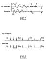
- FIG. 1 is a schematic representation of an engine thermal 1 which is for example a four-cylinder engine in line.
- the engine 1 comprises four cylinders (hereinafter referred to as C 1 , C 2 , C 3 , C 4 ) in each of which moves a piston connected by a connecting rod to a crankshaft 2 secured to one of its ends. , a steering wheel 3.
- Reciprocating pistons, connecting rods and crankshaft 2 and the movable steering wheel 3 constitute all the elements moving motor 1.
- the engine 1 comprises a starter 4 which can be constituted by a electric motor or by a reversible alternator.
- Starter 4 features a control element 4 'for establishing or cutting the power supply starter motor 4 from the battery of the motor vehicle.
- Engine 1 is an engine with indirect fuel injection in the intake manifolds of each of the engine cylinders. Injectors are controlled by an electronic control box 5 which makes it possible to to realize the synchronization of the injections with the displacement of the elements moving motor 1.
- the motor vehicle on which the engine 1 is mounted comprises a calculator 6 enabling different monitoring and control of the motor vehicle and in particular of the engine 1.
- the computer 6 is connected to the control box 5 of fuel injection into the engine cylinders, so as to ensure a synchronization of the fuel injection with the position of the pistons and stopping fuel injection into the intake manifolds of cylinders, at a given moment to obtain an engine stop in a desired position.
- a sensor 7 (or several sensors) are arranged near the steering wheel 3 for measuring the instantaneous speed of rotation of the engine and for determine at any moment the angular position of the steering wheel 3 and the crankshaft 2 corresponding to a defined position of each of the pistons inside inline cylinders of the engine 1.
- the information of the sensor 7 is transmitted to the calculator 6 which is programmed to determine, when an engine stop is commanded, the instant precise order to which the order of cut-off of the injection must be transmitted to the housing 5.
- the calculator 6 is connected to the housing 4 'control starter 4.
- control box ignition is also connected to the computer 6.
- the housing 5 controls both the injection of fuel in the cylinders that ignition of the fuel injected into the cylinders.
- the calculator 6 receives information that allows it to determine whether a stopping order of the motor 1 of the motor vehicle must be given.
- the computer 6 determines, from the speed and the angular position of the rotating part 2, 3 of the transmitted by sensors such as the sensor 7, the exact instant at which an order to interrupt the fuel injection and / or interruption of the ignition must be transmitted to the control box 5.
- the calculator program is used to determine the exact moment the order of interruption of the injection must be transmitted to obtain a stopping the engine in a well-defined position which is chosen to facilitate the subsequent restart of the engine.
- the stop position is stored in the computer, for its taken into account during a subsequent restart of the engine.
- the interruption of fuel injection in engine cylinders at a moment perfectly determined according to the speed and the angular position of the crankshaft avoids, in particular, trigger the engine stop in the middle of an injection phase in a cylinder.
- DPF particulate filter
- the amount of fuel injected and the ignition angle of the first combustions are specific to fast hot start. This operation in open loop is determined by a specific focus of the warm restart. Wealth regulation is activated the fastest possible to avoid any pollution.
- the ignition angle allows in particular to play on the engine revving, with a view to improving the quality and smoothness of startup.
- the stop can be obtained in two plates 9 and 9 ', the angular position of the crankshaft extending on both sides from a central position, on 30 °.
- the stop can be obtained in a single range 11 of angular position of the crankshaft.
- the restart with a fuel injection in a well-defined cylinder allows to get a start, that is to say a first combustion in the engine cylinders, in about a quarter turn of the crankshaft.
- a start that is to say a first combustion in the engine cylinders
- the process according to the invention therefore makes it possible to solicit a great deal minus the starter and make the restart much faster with less pollution from the exhaust.
- the following engine stop adjustment method is used the invention so as to obtain a programmed stopping position of the elements motor, this position being kept in memory by the computer of the motor vehicle.
- the engine stop is controlled by the interruption of the injection of fuel and / or by interrupting the ignition, the two breaking orders can be given simultaneously or at different times.
- ignition is performed loads from the first revolution of the crankshaft, controlling, thanks to a physical target attached to the crankshaft, the precise position moving parts of the engine. This controls the ignition of the load of fuel in the cylinder stopped in compression position, then in the cylinder stopped in the intake phase.
- These ignitions correspond to second specific positions of the rotating part of the engine.
- the flywheel 3 secured to the crankshaft 2 carries two targets 12 and 12 'placed at 180 ° from each other, considering a rotation about the axis common to the steering wheel 3 and the crankshaft 2.
- the sensor 7 which is preferably a Hall effect sensor detects the passing the targets 12 and 12 'in a position corresponding to the neutral position top of the pistons in the engine cylinders.
- the sensor 7 controls the loading of a coils for ignition in a cylinder for a very long time short and causes ignition in the cylinder. This causes ignition in a cylinder in compression very shortly after the rotation the engine for restarting, because of obtaining a stopping position precision of the engine and the determination of the first cylinder in compression in which one must realize the ignition. Ignition in the first compression cylinder is made after a quarter turn of the crankshaft at more.
- Fuel injection during engine shutdown can be performed in order to limit the consumption and the pollution by the exhaust gases. Indeed, it is not mandatory to inject fuel in all cylinders after the engine stop order but only in those that go serve for the quick restart of the engine, that is to say essentially the cylinder whose piston stops in compression phase and possibly the one whose piston stops during the intake phase.
- the right moment for inject the fuel into the desired cylinders can be deduced from the measurement speed of the motor during the stop made by a suitable sensor which can be the sensor 7 shown in Figures 1 and 4.
- the Hall effect sensor of the target passage of the camshaft is preferably used to determine the phases in the engine cylinders, the Hall effect sensor associated with the integral flywheel of the crankshaft being preferably used to control the ignition in the cylinders ensuring the start.
- An inductive sensor placed in the vicinity of the integral wheel of the crankshaft to control ignition and fuel injections in the desired cylinders and a Hall effect sensor the passage of four targets integral with the camshaft, for the recognition of the phases of the engine.
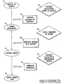
- Table 1 gives the sequences of the operations in each of the cylinders, during the normal operation of the engine.
- the firing order of the cylinders is as follows: C 1 , C 3 , C 4 , C 2 , C 1 , ...
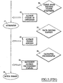
- the computer decides to stop the engine to perform the function "stop and start".
- the computer controls the switch off of ignition and injection (possibly at different times).
- the engine loses the speed from the idle speed and, during the engine stop, the engine determines the engine speed variation and the stopping position.
- fuel is injected into the cylinders in which ignition will be performed as soon as possible after the restart, that is to say in the cylinder C 1 in which a complete phase of admission during the last revolution of the engine and which is in compression phase at the time of the complete stop and in the cylinder C 3 in the intake phase, at the time of the stop.
- the computer decides to restart the engine to complete the "stop and start” function.
- the command calculator starter power and motor starts its first turn.
- the computer When passing a target in front of the sensor of the camshaft (Hall effect sensor), the computer controls the start of charging of an ignition coil corresponding to the cylinder C 1 stopped in compression. In parallel, the computer controls a fuel injection into the tubing of cylinder C 4 stopped in the exhaust phase. The ignition in the cylinder C 1 stopped in compression is then performed, either after a minimum charging time of the coil (timed ignition) or when the falling edge of the signal of the target is identified.
- the engine is then accelerated by the displacement of the piston which was stopped in compression in the cylinder C 1 .
- the calculator then switches to a calculation mode of ignition and injection engine control, this passage being carried out either at the beginning of the charge of the coil by passing a target in front of the sensor of the camshaft, either by locating missing teeth on a toothing of the steering wheel.
- the ignition is controlled in cylinder C 1 where the air-fuel mixture has been prepared before shutdown and then compressed, and then in cylinder C 3 .
- the other cylinders continue their normal sequence.
- the main advantages of the process according to the invention are to obtain a great regularity of the engine stop with a low dispersion of the stopping position which is favorable for the restart of the engine, to improve synchronization of the injection with the phases of the engine cylinders and to reduce the pollution of the exhaust gases.
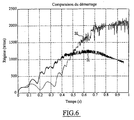
- FIG. 6 shows the variations of the speed of a motor with indirect injection and controlled ignition, as a function of time, during a warm restart, in the case of a shutdown and a restart performed according to the invention (curve 31) or according to a usual technique of setting implementation of the "stop and start” function (curve 32).
- the boot is also softer, which is of great interest as for the comfort of the motor vehicle propelled by the engine and the holding engine in long service.
- a precise calibration of the sequential injections performed in the cylinders and ignition at the time of restart allows to obtain a soft restart by limiting the oscillations by setting the injected quantities and opening times of the intake valves.
- the speed and position measurements of the crankshaft can be carried out by any means present on the motor vehicle or any means specific method used for carrying out the process of the invention.
- the invention applies to any engine with indirect injection and ignition ordered.
- the stopping of the engine can be obtained by interrupting ignition and / or injection, these two operations that can be performed simultaneously or separately.
- the ignition control at a precise moment in the cylinder in compression at the time of stopping the engine and then in the cylinder in position intake during shutdown allows the engine to be started from the first turn of the crankshaft, reproducibly.
- the invention applies in particular to motor vehicles whose calculator allows to perform the "stop and start” function for stopping and restarting the engine, automatically.
Landscapes
- Engineering & Computer Science (AREA)
- Chemical & Material Sciences (AREA)
- Combustion & Propulsion (AREA)
- Mechanical Engineering (AREA)
- General Engineering & Computer Science (AREA)
- Output Control And Ontrol Of Special Type Engine (AREA)
- Electrical Control Of Air Or Fuel Supplied To Internal-Combustion Engine (AREA)
- Control Of Vehicle Engines Or Engines For Specific Uses (AREA)
- Combined Controls Of Internal Combustion Engines (AREA)
- Ignition Installations For Internal Combustion Engines (AREA)
- Electrical Control Of Ignition Timing (AREA)
Description
- on mesure en continu la vitesse de rotation et la position du piston et de la partie tournante du moteur, et on coupe l'injection de carburant pour des valeurs prédéterminées de la vitesse et de la position angulaire de la partie tournante du moteur pour obtenir l'arrêt du piston et de la partie tournante dans une position prédéterminée,
- on injecte une charge de carburant dans la tubulure d'admission du cylindre en phase d'admission pendant un dernier tour du moteur avant l'arrêt en position prédéterminée,
- au redémarrage du moteur après l'arrêt par mise en rotation de la partie tournante du moteur, on repère la réalisation de la phase de compression dans le cylindre et on réalise un allumage de la charge dans le cylindre en phase de compression, et
- on effectue l'injection et l'allumage de charges successives dans l'au moins un cylindre suivant une séquence prédéterminée, afin d'optimiser la consommation et les émissions et de limiter la survitesse du moteur au démarrage, favorisant ainsi la qualité du démarrage.
- Adm
- Admission
- Inj
- Injection
- Ech
- Echappement
- Comp
- Compression
- Comb
- Combustion
- Det
- Détente
- A
- Allumage
- Arr
- Arrêt complet du moteur.


Claims (9)
- Procédé d'arrêt et de redémarrage d'un moteur à combustion interne à injection indirecte et à allumage commandé (1) comportant au moins un cylindre (C1, C2, C3, C4) dans lequel se déplace un piston et une tubulure d'admission de carburant communiquant avec le cylindre et une partie tournante (23) mise en rotation par le piston, par l'intermédiaire d'une bielle, caractérisé par le fait :qu'on mesure en continu la vitesse de rotation et la position du piston et de la partie tournante (23) du moteur (1), et qu'on coupe l'injection de carburant pour des valeurs prédéterminées de la vitesse et de la position angulaire de la partie tournante (23) du moteur (1) pour obtenir l'arrêt du piston et de la partie tournante dans une position prédéterminée,qu'on injecte une charge de carburant dans la tubulure d'admission du cylindre (C1) en phase d'admission pendant un dernier tour du moteur (1) avant l'arrêt en position prédéterminée,qu'au redémarrage du moteur après l'arrêt par mise en rotation de la partie tournante (23) du moteur, on repère la réalisation de la phase de compression dans le cylindre (C1) et on réalise un allumage de la charge dans le cylindre (C1) en phase de compression, etqu'on effectue l'injection et l'allumage de charges successives dans l'au moins un cylindre (C1, C2, C3, C4) suivant une séquence prédéterminée, afin d'optimiser la consommation et les émissions et de limiter la survitesse du moteur (1) au démarrage, favorisant ainsi la qualité du démarrage.
- Procédé suivant la revendication 1, caractérisé par le fait qu'on mesure la vitesse et la position angulaire de la partie tournante (2, 3) du moteur (1), à l'aide d'au moins un capteur (7) de la vitesse et de la position angulaire d'un volant (3) solidaire d'un vilebrequin (2) du moteur (1).
- Procédé suivant l'une quelconque des revendications 1 et 2, caractérisé par le fait :qu'on mesure en continu la vitesse de rotation et la position angulaire de la partie tournante (2, 3) du moteur (1), etqu'on interrompt l'un au moins de l'allumage et de l'injection de carburant pour des valeurs prédéterminées de la vitesse et de la position angulaire de la partie tournante (2, 3) du moteur (1), pour obtenir l'arrêt des parties mobiles (2, 3) du moteur dans une position prédéterminée permettant de faciliter le redémarrage du moteur (1).
- Procédé suivant la revendication 3, caractérisé par le fait qu'on détermine la vitesse et la position angulaire de la partie tournante (2, 3) du moteur (1) à l'aide d'un capteur de la vitesse et de la position angulaire de l'un au moins d'un volant (3) solidaire d'un vilebrequin (2) du moteur (1) et d'un arbre à cames de commande des soupapes du moteur (1).
- Procédé suivant la revendication 1, caractérisé par le fait qu'on réalise le redémarrage du moteur, en un quart de tour au plus de l'ensemble (2, 3) du moteur (1) et en un tour un quart si l'on ne réalise pas d'injection au cours du dernier tour avant l'arrêt.
- Procédé suivant l'une quelconque des revendications 1 à-5, dans le cas d'un moteur comportant plusieurs cylindres (C1, C2, C3, C4), et de préférence quatre cylindres, en ligne, caractérisé par le fait que, pendant le dernier tour avant l'arrêt du moteur précédant le redémarrage, on injecte des charges de carburant dans la tubulure d'admission du cylindre (C1) du moteur dans lequel le piston est en position d'admission pendant le dernier tour avant l'arrêt du moteur et en position de compression au moment de l'arrêt, et dans un second cylindre (C3) du moteur en phase d'admission au moment de l'arrêt.
- Procédé suivant l'une quelconque des revendications 1 à 4, caractérisé par le fait que, pour le redémarrage du moteur, on réalise un allumage dans le cylindre (C1) dont le piston est en position de compression au moment de l'arrêt du moteur (1), puis dans le cylindre (C3) dans lequel le piston est en position d'admission au moment de l'arrêt du moteur (1).
- Procédé suivant l'une quelconque des revendications 1 à 7, caractérisé par le fait qu'on réalise un calibrage précis des injections séquentielles et de l'allumage à réaliser pendant le redémarrage et qu'on réalise les injections séquentielles et l'allumage selon les valeurs obtenues par le calibrage.
- Procédé suivant la revendication 8, caractérisé par le fait qu'on détermine par le calibrage les quantités de carburant à injecter séquentiellement dans les cylindres (C1, C2, C3, C4) et les angles d'allumage, pendant le redémarrage du moteur (1).
Applications Claiming Priority (3)
| Application Number | Priority Date | Filing Date | Title |
|---|---|---|---|
| FR0110131 | 2001-07-27 | ||
| FR0110131A FR2827911B1 (fr) | 2001-07-27 | 2001-07-27 | Procede de reglage de l'arret et procede de redemarrage d'un moteur a combustion interne |
| PCT/FR2002/002693 WO2003012273A2 (fr) | 2001-07-27 | 2002-07-26 | Procede d'arret et de redemarrage d'un moteur a combustion inter ne a injection indirecte |
Publications (2)
| Publication Number | Publication Date |
|---|---|
| EP1454048A2 EP1454048A2 (fr) | 2004-09-08 |
| EP1454048B1 true EP1454048B1 (fr) | 2005-10-19 |
Family
ID=8866036
Family Applications (1)
| Application Number | Title | Priority Date | Filing Date |
|---|---|---|---|
| EP02772462A Expired - Lifetime EP1454048B1 (fr) | 2001-07-27 | 2002-07-26 | Procede d'arret et de redemarrage d'un moteur a combustion interne a injection indirecte |
Country Status (11)
| Country | Link |
|---|---|
| US (1) | US7011063B2 (fr) |
| EP (1) | EP1454048B1 (fr) |
| JP (1) | JP2004537673A (fr) |
| KR (1) | KR20040037059A (fr) |
| CN (1) | CN100587245C (fr) |
| AT (1) | ATE307279T1 (fr) |
| AU (1) | AU2002337230A1 (fr) |
| DE (1) | DE60206799T2 (fr) |
| ES (1) | ES2251619T3 (fr) |
| FR (1) | FR2827911B1 (fr) |
| WO (1) | WO2003012273A2 (fr) |
Cited By (1)
| Publication number | Priority date | Publication date | Assignee | Title |
|---|---|---|---|---|
| WO2004038201A1 (fr) | 2002-10-22 | 2004-05-06 | Toyota Jidosha Kabushiki Kaisha | Systeme de commande de demarrage pour moteur a combustion interne |
Families Citing this family (48)
| Publication number | Priority date | Publication date | Assignee | Title |
|---|---|---|---|---|
| JP3941705B2 (ja) * | 2003-02-13 | 2007-07-04 | トヨタ自動車株式会社 | 内燃機関の停止始動制御装置 |
| EP1464833A3 (fr) * | 2003-04-03 | 2008-06-11 | Continental Automotive GmbH | Procédé de préparation d'un mélange carburant-air pour démarrage direct d'un moteur à combustion |
| DE10322305A1 (de) * | 2003-05-17 | 2004-12-02 | Daimlerchrysler Ag | Verfahren zum Abstellen einer Brennkraftmaschine |
| JP4062264B2 (ja) * | 2003-06-06 | 2008-03-19 | アイシン・エィ・ダブリュ株式会社 | 車両駆動制御装置、車両駆動制御方法及びプログラム |
| US7007667B2 (en) * | 2003-07-22 | 2006-03-07 | Hitachi, Ltd. | Cold start fuel control system |
| DE60329396D1 (de) * | 2003-11-04 | 2009-11-05 | Ford Global Tech Llc | System und Verfahren für die Steuerung der Kraftstoffeinspritzung in einem Motor |
| DE10351891B4 (de) * | 2003-11-06 | 2017-03-30 | Robert Bosch Gmbh | Verfahren und Steuergerät zum Neustarten einer Brennkraftmaschine |
| EP1586765B1 (fr) * | 2004-04-15 | 2011-06-29 | TEMIC Automotive Electric Motors GmbH | Procédé et système de commande pour positioner les vilebrequine lors de l'arrêt d'un moteur à combustion |
| US7142973B2 (en) * | 2004-06-11 | 2006-11-28 | Denso Corporation | Engine control apparatus designed to ensure accuracy in determining engine position |
| JP4345587B2 (ja) * | 2004-06-21 | 2009-10-14 | トヨタ自動車株式会社 | 内燃機関の機関始動制御システム |
| JP4424153B2 (ja) | 2004-10-22 | 2010-03-03 | トヨタ自動車株式会社 | 内燃機関装置および内燃機関の停止位置推定方法並びに内燃機関の制御方法 |
| EP1657418B1 (fr) * | 2004-11-16 | 2008-03-19 | Ford Global Technologies, LLC, A subsidary of Ford Motor Company | Moteur à combustion interne et procédé pour le contrôle de l'arrêt du moteur |
| US7654238B2 (en) * | 2004-11-08 | 2010-02-02 | Ford Global Technologies, Llc | Systems and methods for controlled shutdown and direct start for internal combustion engine |
| JP4385940B2 (ja) | 2004-11-17 | 2009-12-16 | トヨタ自動車株式会社 | 内燃機関装置およびこれを搭載する自動車並びに内燃機関の運転停止方法 |
| JP4371047B2 (ja) * | 2004-12-08 | 2009-11-25 | トヨタ自動車株式会社 | 内燃機関装置および内燃機関の制御方法 |
| JP4453536B2 (ja) * | 2004-12-10 | 2010-04-21 | トヨタ自動車株式会社 | 駆動装置およびこれを搭載する自動車並びに駆動装置の制御方法 |
| JP4557816B2 (ja) * | 2004-12-17 | 2010-10-06 | トヨタ自動車株式会社 | エンジン始動制御装置、その方法及びそれを搭載した車両 |
| KR100707328B1 (ko) * | 2005-01-18 | 2007-04-13 | 닛산 지도우샤 가부시키가이샤 | 내연 기관의 시동 장치 |
| JP4753604B2 (ja) * | 2005-03-30 | 2011-08-24 | 富士通テン株式会社 | エコランシステム、エコラン制御装置、及びナビゲーション装置 |
| EP1881188A1 (fr) * | 2005-05-13 | 2008-01-23 | Toyota Jidosha Kabushiki Kaisha | Controleur de demarrage d un moteur a combustion interne |
| JP2006348826A (ja) | 2005-06-15 | 2006-12-28 | Yanmar Co Ltd | 燃料噴射制御装置 |
| US7461621B2 (en) * | 2005-09-22 | 2008-12-09 | Mazda Motor Corporation | Method of starting spark ignition engine without using starter motor |
| JP4673767B2 (ja) * | 2006-02-28 | 2011-04-20 | トヨタ自動車株式会社 | 内燃機関の自動停止装置及びこの自動停止装置を備えた自動車用内燃機関 |
| JP4434241B2 (ja) * | 2007-07-06 | 2010-03-17 | トヨタ自動車株式会社 | 内燃機関の停止始動制御装置 |
| FR2926110B1 (fr) * | 2008-01-09 | 2013-03-22 | Siemens Vdo Automotive | Dispositif de controle de fonctionnement d'un moteur a combustion interne, a rephasage perfectionne d'evenements d'injection. |
| US7624712B1 (en) * | 2008-05-19 | 2009-12-01 | Ford Global Technologies, Llc | Approach for engine start synchronization |
| JP4529190B2 (ja) * | 2008-08-08 | 2010-08-25 | 株式会社デンソー | エンジン停止制御装置 |
| JP5114340B2 (ja) * | 2008-08-08 | 2013-01-09 | 株式会社デンソー | エンジン停止制御装置 |
| JP5209454B2 (ja) * | 2008-12-09 | 2013-06-12 | 本田技研工業株式会社 | 内燃機関の停止時に点火を停止する時期を制御する装置 |
| DE102009010925B4 (de) * | 2009-02-27 | 2019-08-08 | Dr. Ing. H.C. F. Porsche Aktiengesellschaft | Verfahren zum Betreiben einer Brennkraftmaschine |
| FR2950388B1 (fr) * | 2009-09-23 | 2012-04-20 | Peugeot Citroen Automobiles Sa | Procede de prediction du regime de rotation d'un vilebrequin de moteur en phase de fin de rotation et application du procede a la prediction du cylindre d'arret |
| JP5141673B2 (ja) | 2009-12-04 | 2013-02-13 | 株式会社デンソー | 内燃機関のアイドルストップ制御装置 |
| US8099998B2 (en) | 2010-05-19 | 2012-01-24 | Delphi Technologies, Inc. | Apparatus and method for estimating stopped engine crank angle |
| US8091411B2 (en) | 2010-05-27 | 2012-01-10 | Delphi Technologies, Inc. | Apparatus and method for estimating bounce back angle of a stopped engine |
| WO2013038480A1 (fr) * | 2011-09-12 | 2013-03-21 | トヨタ自動車株式会社 | Dispositif de commande de véhicule |
| US8423271B2 (en) | 2011-11-09 | 2013-04-16 | Ford Global Technologies, Llc | Method for fueling an engine at start |
| KR101339272B1 (ko) * | 2012-12-17 | 2013-12-09 | 기아자동차 주식회사 | 전자식 연속 가변 밸브 타이밍 장치의 제어방법 |
| CN103953451B (zh) * | 2013-05-24 | 2016-07-13 | 潍柴动力股份有限公司 | 获取发动机停车缸号的方法、装置及发动机 |
| DE102013210392A1 (de) * | 2013-06-05 | 2014-12-11 | Robert Bosch Gmbh | Verfahren zum Betreiben einer Verbrennungskraftmaschine |
| EP3126655B1 (fr) * | 2014-03-31 | 2020-10-28 | Cummins, Inc. | Synchronisation rapide de moteur pour gestion du redémarrage |
| SE540546C2 (en) * | 2014-10-23 | 2018-09-25 | Scania Cv Ab | Device for detecting speed of a rotatable element, method and vehicle |
| CN107559094B (zh) * | 2017-08-25 | 2019-10-01 | 科力远混合动力技术有限公司 | 无离合器混合动力汽车发动机停机抖动控制方法 |
| CN108952959A (zh) * | 2018-08-16 | 2018-12-07 | 重庆卓力标准件制造有限公司 | 一种曲轴连杆总成 |
| CN109340012A (zh) * | 2018-09-29 | 2019-02-15 | 中国第汽车股份有限公司 | 一种缸内直喷发动机快速智能启动控制方法 |
| JP7310461B2 (ja) * | 2019-09-03 | 2023-07-19 | トヨタ自動車株式会社 | パワートレーンシステム |
| US10920732B1 (en) | 2020-02-06 | 2021-02-16 | Ford Global Technologies, Llc | Methods and systems for engine start following idle-stop |
| CN111946455A (zh) * | 2020-07-09 | 2020-11-17 | 浙江亚特电器有限公司 | 一种易点火的四冲程发动机 |
| US11708811B2 (en) | 2021-03-09 | 2023-07-25 | Ford Global Technologies, Llc | Adjusted ignition timing for engine restart |
Family Cites Families (17)
| Publication number | Priority date | Publication date | Assignee | Title |
|---|---|---|---|---|
| US4364343A (en) * | 1981-05-08 | 1982-12-21 | General Motors Corporation | Automatic engine shutdown and restart system |
| DE4230616A1 (de) * | 1992-09-12 | 1994-03-17 | Bosch Gmbh Robert | Einrichtung zur Erkennung der Stellung wenigstens einer, eine Referenzmarke aufweisenden Welle |
| DE19527503A1 (de) * | 1995-07-27 | 1997-01-30 | Bosch Gmbh Robert | Elektronisches Steuersystem für eine Brennkraftmaschine |
| US6098585A (en) * | 1997-08-11 | 2000-08-08 | Ford Global Technologies, Inc. | Multi-cylinder four stroke direct injection spark ignition engine |
| DE19741294A1 (de) * | 1997-09-19 | 1999-03-25 | Bosch Gmbh Robert | Antrieb eines Kraftfahrzeuges |
| GB9821507D0 (en) | 1998-10-03 | 1998-11-25 | Ford Motor Co | Synchronisation of internal combustion engine |
| JP4076106B2 (ja) * | 1998-12-28 | 2008-04-16 | 本田技研工業株式会社 | エンジン停止始動制御装置を搭載した軽車両 |
| JP2000199445A (ja) * | 1998-12-28 | 2000-07-18 | Hitachi Ltd | エンジン駆動モ―タ制御装置 |
| JP3631036B2 (ja) * | 1999-03-09 | 2005-03-23 | 本田技研工業株式会社 | ハイブリッド車両のエンジン制御装置 |
| EP1036928B1 (fr) * | 1999-03-18 | 2007-05-16 | Mitsubishi Jidosha Kogyo Kabushiki Kaisha | Dispositif et méthode de démarrage pour moteur à combustion interne à injection directe |
| JP2001123865A (ja) * | 1999-10-26 | 2001-05-08 | Sanshin Ind Co Ltd | 燃料噴射式4サイクルエンジン |
| JP2001152891A (ja) * | 1999-11-29 | 2001-06-05 | Hitachi Ltd | エンジンの燃料カット方法及びその方法を備えた燃料制御装置 |
| JP3678095B2 (ja) * | 1999-12-17 | 2005-08-03 | 三菱自動車工業株式会社 | 内燃機関の制御装置 |
| DE19960984A1 (de) * | 1999-12-17 | 2001-06-21 | Bosch Gmbh Robert | Verfahren zur Auslaufsteuerung einer Brennkraftmaschine |
| DE10030000A1 (de) * | 1999-12-28 | 2001-07-05 | Bosch Gmbh Robert | Starteranordnung für eine Brennkraftmaschine und Verfahren zur Steuerung derselben |
| US6499342B1 (en) * | 2000-09-05 | 2002-12-31 | Ford Global Technologies, Inc. | Method of determining the stopping position of an internal combustion engine |
| US6453864B1 (en) * | 2001-01-16 | 2002-09-24 | General Motors Corporation | Crankshaft rotation control in a hybrid electric vehicle |
-
2001
- 2001-07-27 FR FR0110131A patent/FR2827911B1/fr not_active Expired - Fee Related
-
2002
- 2002-07-26 CN CN02817705A patent/CN100587245C/zh not_active Expired - Fee Related
- 2002-07-26 DE DE60206799T patent/DE60206799T2/de not_active Expired - Lifetime
- 2002-07-26 AU AU2002337230A patent/AU2002337230A1/en not_active Abandoned
- 2002-07-26 EP EP02772462A patent/EP1454048B1/fr not_active Expired - Lifetime
- 2002-07-26 US US10/484,700 patent/US7011063B2/en not_active Expired - Fee Related
- 2002-07-26 ES ES02772462T patent/ES2251619T3/es not_active Expired - Lifetime
- 2002-07-26 WO PCT/FR2002/002693 patent/WO2003012273A2/fr active IP Right Grant
- 2002-07-26 KR KR10-2004-7001210A patent/KR20040037059A/ko not_active Withdrawn
- 2002-07-26 AT AT02772462T patent/ATE307279T1/de not_active IP Right Cessation
- 2002-07-26 JP JP2003517432A patent/JP2004537673A/ja active Pending
Cited By (1)
| Publication number | Priority date | Publication date | Assignee | Title |
|---|---|---|---|---|
| WO2004038201A1 (fr) | 2002-10-22 | 2004-05-06 | Toyota Jidosha Kabushiki Kaisha | Systeme de commande de demarrage pour moteur a combustion interne |
Also Published As
| Publication number | Publication date |
|---|---|
| ATE307279T1 (de) | 2005-11-15 |
| FR2827911A1 (fr) | 2003-01-31 |
| FR2827911B1 (fr) | 2004-01-30 |
| JP2004537673A (ja) | 2004-12-16 |
| WO2003012273A2 (fr) | 2003-02-13 |
| ES2251619T3 (es) | 2006-05-01 |
| AU2002337230A1 (en) | 2003-02-17 |
| DE60206799D1 (de) | 2005-11-24 |
| KR20040037059A (ko) | 2004-05-04 |
| CN100587245C (zh) | 2010-02-03 |
| CN1553990A (zh) | 2004-12-08 |
| DE60206799T2 (de) | 2006-04-20 |
| US20040216719A1 (en) | 2004-11-04 |
| WO2003012273A3 (fr) | 2004-01-22 |
| EP1454048A2 (fr) | 2004-09-08 |
| US7011063B2 (en) | 2006-03-14 |
Similar Documents
| Publication | Publication Date | Title |
|---|---|---|
| EP1454048B1 (fr) | Procede d'arret et de redemarrage d'un moteur a combustion interne a injection indirecte | |
| FR2851303A1 (fr) | Procede et dispositif de demarrage d'un moteur a combustion interne | |
| FR2769048A1 (fr) | Procede pour demarrer un moteur a combustion interne, notamment d'un vehicule automobile et vehicule automobile appliquant ce procede | |
| FR2851302A1 (fr) | Procede de gestion d'un moteur a combustion interne | |
| FR2822196A1 (fr) | Procede de demarrage sans demarreur d'un moteur a combustion interne a plusieurs cylindres | |
| FR2815087A1 (fr) | Dispositif pour demarrer un moteur a combustion interne | |
| US7191747B2 (en) | Method for starting an internal combustion engine | |
| FR3005490A1 (fr) | Procede de demarrage a froid d'un moteur a combustion interne a allumage commande fonctionnant avec un carburant comportant de l'ethanol | |
| EP0127510B1 (fr) | Procédé de coupure de l'injection de carburant pendant les phases de décélération d'un moteur à combustion interne | |
| WO1999002832A1 (fr) | Procede d'injection de carburant au demarrage d'un moteur a combustion interne | |
| WO2008071670A1 (fr) | Procede pour ameliorer le demarrage a froid d'un moteur diesel | |
| FR2862722A1 (fr) | Procede et appareil de commande de redemarrage d'un moteur thermique | |
| FR2899283A1 (fr) | Procede d'injection de carburant dans un moteur a combustion interne | |
| EP2491241A1 (fr) | Procede de commande de l'arret automatique d'un moteur a combustion interne de vehicule automobile | |
| WO2021156409A1 (fr) | Purge d'oxygene dans un catalyseur d'echappement de vehicule automobile a la reprise d'injection | |
| FR3051226B1 (fr) | Procede de pilotage d’au moins un dephaseur d’un moteur thermique de vehicule automobile lors d’une phase d’arret | |
| FR2717227A1 (fr) | Procédé d'injection de carburant pour moteur à combustion interne à injection directe et allumage commandé. | |
| EP0614005B1 (fr) | Procédé de commande d'injection pour moteur à injection multipoints à allumage commande | |
| JP6071463B2 (ja) | 内燃機関 | |
| FR2792682A1 (fr) | Appareil de commande pour moteur a combustion interne | |
| FR2739141A1 (fr) | Procede de determination de la richesse optimale d'un melange air / carburant alimentant un moteur a combustion interne et dispositif correspondant | |
| WO2013104842A1 (fr) | Procede de commande de l'avance pour l'allumage commande d'un moteur a combustion interne | |
| FR3140910A1 (fr) | Procédé de chauffage d’un catalyseur dans un véhicule à motorisation hybride | |
| FR3120659A1 (fr) | Calculateur de contrôle moteur pour véhicule automobile | |
| FR3141217A1 (fr) | Procédé de gestion d’une phase de redémarrage d’un moteur à combustion interne en mode dégradé |
Legal Events
| Date | Code | Title | Description |
|---|---|---|---|
| PUAI | Public reference made under article 153(3) epc to a published international application that has entered the european phase |
Free format text: ORIGINAL CODE: 0009012 |
|
| 17P | Request for examination filed |
Effective date: 20040123 |
|
| AK | Designated contracting states |
Kind code of ref document: A2 Designated state(s): AT BE BG CH CY CZ DE DK EE ES FI FR GB GR IE IT LI LU MC NL PT SE SK TR |
|
| AX | Request for extension of the european patent |
Extension state: AL LT LV MK RO SI |
|
| GRAP | Despatch of communication of intention to grant a patent |
Free format text: ORIGINAL CODE: EPIDOSNIGR1 |
|
| GRAS | Grant fee paid |
Free format text: ORIGINAL CODE: EPIDOSNIGR3 |
|
| GRAA | (expected) grant |
Free format text: ORIGINAL CODE: 0009210 |
|
| AK | Designated contracting states |
Kind code of ref document: B1 Designated state(s): AT BE BG CH CY CZ DE DK EE ES FI FR GB GR IE IT LI LU MC NL PT SE SK TR |
|
| PG25 | Lapsed in a contracting state [announced via postgrant information from national office to epo] |
Ref country code: AT Free format text: LAPSE BECAUSE OF FAILURE TO SUBMIT A TRANSLATION OF THE DESCRIPTION OR TO PAY THE FEE WITHIN THE PRESCRIBED TIME-LIMIT Effective date: 20051019 Ref country code: IE Free format text: LAPSE BECAUSE OF FAILURE TO SUBMIT A TRANSLATION OF THE DESCRIPTION OR TO PAY THE FEE WITHIN THE PRESCRIBED TIME-LIMIT Effective date: 20051019 Ref country code: NL Free format text: LAPSE BECAUSE OF FAILURE TO SUBMIT A TRANSLATION OF THE DESCRIPTION OR TO PAY THE FEE WITHIN THE PRESCRIBED TIME-LIMIT Effective date: 20051019 Ref country code: FI Free format text: LAPSE BECAUSE OF FAILURE TO SUBMIT A TRANSLATION OF THE DESCRIPTION OR TO PAY THE FEE WITHIN THE PRESCRIBED TIME-LIMIT Effective date: 20051019 Ref country code: SK Free format text: LAPSE BECAUSE OF FAILURE TO SUBMIT A TRANSLATION OF THE DESCRIPTION OR TO PAY THE FEE WITHIN THE PRESCRIBED TIME-LIMIT Effective date: 20051019 Ref country code: CZ Free format text: LAPSE BECAUSE OF FAILURE TO SUBMIT A TRANSLATION OF THE DESCRIPTION OR TO PAY THE FEE WITHIN THE PRESCRIBED TIME-LIMIT Effective date: 20051019 |
|
| REG | Reference to a national code |
Ref country code: GB Ref legal event code: FG4D Free format text: NOT ENGLISH |
|
| REG | Reference to a national code |
Ref country code: CH Ref legal event code: EP |
|
| GBT | Gb: translation of ep patent filed (gb section 77(6)(a)/1977) | ||
| REG | Reference to a national code |
Ref country code: IE Ref legal event code: FG4D Free format text: LANGUAGE OF EP DOCUMENT: FRENCH |
|
| REF | Corresponds to: |
Ref document number: 60206799 Country of ref document: DE Date of ref document: 20051124 Kind code of ref document: P |
|
| PG25 | Lapsed in a contracting state [announced via postgrant information from national office to epo] |
Ref country code: BG Free format text: LAPSE BECAUSE OF FAILURE TO SUBMIT A TRANSLATION OF THE DESCRIPTION OR TO PAY THE FEE WITHIN THE PRESCRIBED TIME-LIMIT Effective date: 20060119 Ref country code: SE Free format text: LAPSE BECAUSE OF FAILURE TO SUBMIT A TRANSLATION OF THE DESCRIPTION OR TO PAY THE FEE WITHIN THE PRESCRIBED TIME-LIMIT Effective date: 20060119 Ref country code: DK Free format text: LAPSE BECAUSE OF FAILURE TO SUBMIT A TRANSLATION OF THE DESCRIPTION OR TO PAY THE FEE WITHIN THE PRESCRIBED TIME-LIMIT Effective date: 20060119 Ref country code: GR Free format text: LAPSE BECAUSE OF FAILURE TO SUBMIT A TRANSLATION OF THE DESCRIPTION OR TO PAY THE FEE WITHIN THE PRESCRIBED TIME-LIMIT Effective date: 20060119 |
|
| PG25 | Lapsed in a contracting state [announced via postgrant information from national office to epo] |
Ref country code: PT Free format text: LAPSE BECAUSE OF FAILURE TO SUBMIT A TRANSLATION OF THE DESCRIPTION OR TO PAY THE FEE WITHIN THE PRESCRIBED TIME-LIMIT Effective date: 20060320 |
|
| NLV1 | Nl: lapsed or annulled due to failure to fulfill the requirements of art. 29p and 29m of the patents act | ||
| REG | Reference to a national code |
Ref country code: ES Ref legal event code: FG2A Ref document number: 2251619 Country of ref document: ES Kind code of ref document: T3 |
|
| REG | Reference to a national code |
Ref country code: IE Ref legal event code: FD4D |
|
| PG25 | Lapsed in a contracting state [announced via postgrant information from national office to epo] |
Ref country code: CH Free format text: LAPSE BECAUSE OF NON-PAYMENT OF DUE FEES Effective date: 20060731 Ref country code: BE Free format text: LAPSE BECAUSE OF NON-PAYMENT OF DUE FEES Effective date: 20060731 Ref country code: LI Free format text: LAPSE BECAUSE OF NON-PAYMENT OF DUE FEES Effective date: 20060731 Ref country code: MC Free format text: LAPSE BECAUSE OF NON-PAYMENT OF DUE FEES Effective date: 20060731 |
|
| PLBE | No opposition filed within time limit |
Free format text: ORIGINAL CODE: 0009261 |
|
| STAA | Information on the status of an ep patent application or granted ep patent |
Free format text: STATUS: NO OPPOSITION FILED WITHIN TIME LIMIT |
|
| 26N | No opposition filed |
Effective date: 20060720 |
|
| REG | Reference to a national code |
Ref country code: GB Ref legal event code: 746 Effective date: 20070117 |
|
| REG | Reference to a national code |
Ref country code: CH Ref legal event code: PL |
|
| BERE | Be: lapsed |
Owner name: PEUGEOT CITROEN AUTOMOBILES S.A. Effective date: 20060731 |
|
| PG25 | Lapsed in a contracting state [announced via postgrant information from national office to epo] |
Ref country code: EE Free format text: LAPSE BECAUSE OF FAILURE TO SUBMIT A TRANSLATION OF THE DESCRIPTION OR TO PAY THE FEE WITHIN THE PRESCRIBED TIME-LIMIT Effective date: 20051019 |
|
| PG25 | Lapsed in a contracting state [announced via postgrant information from national office to epo] |
Ref country code: TR Free format text: LAPSE BECAUSE OF FAILURE TO SUBMIT A TRANSLATION OF THE DESCRIPTION OR TO PAY THE FEE WITHIN THE PRESCRIBED TIME-LIMIT Effective date: 20051019 Ref country code: LU Free format text: LAPSE BECAUSE OF NON-PAYMENT OF DUE FEES Effective date: 20060726 |
|
| PG25 | Lapsed in a contracting state [announced via postgrant information from national office to epo] |
Ref country code: CY Free format text: LAPSE BECAUSE OF FAILURE TO SUBMIT A TRANSLATION OF THE DESCRIPTION OR TO PAY THE FEE WITHIN THE PRESCRIBED TIME-LIMIT Effective date: 20051019 |
|
| REG | Reference to a national code |
Ref country code: ES Ref legal event code: GC2A Effective date: 20110406 |
|
| PGFP | Annual fee paid to national office [announced via postgrant information from national office to epo] |
Ref country code: IT Payment date: 20110618 Year of fee payment: 10 |
|
| PGFP | Annual fee paid to national office [announced via postgrant information from national office to epo] |
Ref country code: ES Payment date: 20110623 Year of fee payment: 10 |
|
| PG25 | Lapsed in a contracting state [announced via postgrant information from national office to epo] |
Ref country code: IT Free format text: LAPSE BECAUSE OF NON-PAYMENT OF DUE FEES Effective date: 20120726 |
|
| PGFP | Annual fee paid to national office [announced via postgrant information from national office to epo] |
Ref country code: GB Payment date: 20130626 Year of fee payment: 12 |
|
| REG | Reference to a national code |
Ref country code: ES Ref legal event code: FD2A Effective date: 20131018 |
|
| PG25 | Lapsed in a contracting state [announced via postgrant information from national office to epo] |
Ref country code: ES Free format text: LAPSE BECAUSE OF NON-PAYMENT OF DUE FEES Effective date: 20120727 |
|
| PGFP | Annual fee paid to national office [announced via postgrant information from national office to epo] |
Ref country code: DE Payment date: 20130621 Year of fee payment: 12 |
|
| PGFP | Annual fee paid to national office [announced via postgrant information from national office to epo] |
Ref country code: FR Payment date: 20130722 Year of fee payment: 12 |
|
| REG | Reference to a national code |
Ref country code: DE Ref legal event code: R119 Ref document number: 60206799 Country of ref document: DE |
|
| GBPC | Gb: european patent ceased through non-payment of renewal fee |
Effective date: 20140726 |
|
| REG | Reference to a national code |
Ref country code: FR Ref legal event code: ST Effective date: 20150331 |
|
| PG25 | Lapsed in a contracting state [announced via postgrant information from national office to epo] |
Ref country code: DE Free format text: LAPSE BECAUSE OF NON-PAYMENT OF DUE FEES Effective date: 20150203 |
|
| REG | Reference to a national code |
Ref country code: DE Ref legal event code: R119 Ref document number: 60206799 Country of ref document: DE Effective date: 20150203 |
|
| PG25 | Lapsed in a contracting state [announced via postgrant information from national office to epo] |
Ref country code: FR Free format text: LAPSE BECAUSE OF NON-PAYMENT OF DUE FEES Effective date: 20140731 Ref country code: GB Free format text: LAPSE BECAUSE OF NON-PAYMENT OF DUE FEES Effective date: 20140726 |