EP1452682A1 - Eckverbinder - Google Patents
Eckverbinder Download PDFInfo
- Publication number
- EP1452682A1 EP1452682A1 EP03025533A EP03025533A EP1452682A1 EP 1452682 A1 EP1452682 A1 EP 1452682A1 EP 03025533 A EP03025533 A EP 03025533A EP 03025533 A EP03025533 A EP 03025533A EP 1452682 A1 EP1452682 A1 EP 1452682A1
- Authority
- EP
- European Patent Office
- Prior art keywords
- pin
- corner connector
- receptacle
- miter
- connector according
- Prior art date
- Legal status (The legal status is an assumption and is not a legal conclusion. Google has not performed a legal analysis and makes no representation as to the accuracy of the status listed.)
- Granted
Links
- 210000001503 joint Anatomy 0.000 claims 1
- 239000000463 material Substances 0.000 description 5
- 239000000853 adhesive Substances 0.000 description 4
- 230000001070 adhesive effect Effects 0.000 description 4
- 230000036316 preload Effects 0.000 description 4
- XAGFODPZIPBFFR-UHFFFAOYSA-N aluminium Chemical compound [Al] XAGFODPZIPBFFR-UHFFFAOYSA-N 0.000 description 3
- 229910052782 aluminium Inorganic materials 0.000 description 3
- 238000005452 bending Methods 0.000 description 2
- 238000005516 engineering process Methods 0.000 description 2
- 238000003780 insertion Methods 0.000 description 2
- 230000037431 insertion Effects 0.000 description 2
- 238000004080 punching Methods 0.000 description 2
- 229910000831 Steel Inorganic materials 0.000 description 1
- 238000005266 casting Methods 0.000 description 1
- 239000000945 filler Substances 0.000 description 1
- 239000011343 solid material Substances 0.000 description 1
- 125000006850 spacer group Chemical group 0.000 description 1
- 239000010959 steel Substances 0.000 description 1
Images

Classifications
-
- E—FIXED CONSTRUCTIONS
- E06—DOORS, WINDOWS, SHUTTERS, OR ROLLER BLINDS IN GENERAL; LADDERS
- E06B—FIXED OR MOVABLE CLOSURES FOR OPENINGS IN BUILDINGS, VEHICLES, FENCES OR LIKE ENCLOSURES IN GENERAL, e.g. DOORS, WINDOWS, BLINDS, GATES
- E06B3/00—Window sashes, door leaves, or like elements for closing wall or like openings; Layout of fixed or moving closures, e.g. windows in wall or like openings; Features of rigidly-mounted outer frames relating to the mounting of wing frames
- E06B3/96—Corner joints or edge joints for windows, doors, or the like frames or wings
- E06B3/964—Corner joints or edge joints for windows, doors, or the like frames or wings using separate connection pieces, e.g. T-connection pieces
- E06B3/968—Corner joints or edge joints for windows, doors, or the like frames or wings using separate connection pieces, e.g. T-connection pieces characterised by the way the connecting pieces are fixed in or on the frame members
- E06B3/9681—Corner joints or edge joints for windows, doors, or the like frames or wings using separate connection pieces, e.g. T-connection pieces characterised by the way the connecting pieces are fixed in or on the frame members by press fit or adhesion
- E06B3/9682—Mitre joints
-
- E—FIXED CONSTRUCTIONS
- E06—DOORS, WINDOWS, SHUTTERS, OR ROLLER BLINDS IN GENERAL; LADDERS
- E06B—FIXED OR MOVABLE CLOSURES FOR OPENINGS IN BUILDINGS, VEHICLES, FENCES OR LIKE ENCLOSURES IN GENERAL, e.g. DOORS, WINDOWS, BLINDS, GATES
- E06B3/00—Window sashes, door leaves, or like elements for closing wall or like openings; Layout of fixed or moving closures, e.g. windows in wall or like openings; Features of rigidly-mounted outer frames relating to the mounting of wing frames
- E06B3/96—Corner joints or edge joints for windows, doors, or the like frames or wings
- E06B3/964—Corner joints or edge joints for windows, doors, or the like frames or wings using separate connection pieces, e.g. T-connection pieces
- E06B3/9645—Mitre joints
-
- E—FIXED CONSTRUCTIONS
- E06—DOORS, WINDOWS, SHUTTERS, OR ROLLER BLINDS IN GENERAL; LADDERS
- E06B—FIXED OR MOVABLE CLOSURES FOR OPENINGS IN BUILDINGS, VEHICLES, FENCES OR LIKE ENCLOSURES IN GENERAL, e.g. DOORS, WINDOWS, BLINDS, GATES
- E06B3/00—Window sashes, door leaves, or like elements for closing wall or like openings; Layout of fixed or moving closures, e.g. windows in wall or like openings; Features of rigidly-mounted outer frames relating to the mounting of wing frames
- E06B3/96—Corner joints or edge joints for windows, doors, or the like frames or wings
- E06B3/964—Corner joints or edge joints for windows, doors, or the like frames or wings using separate connection pieces, e.g. T-connection pieces
- E06B3/968—Corner joints or edge joints for windows, doors, or the like frames or wings using separate connection pieces, e.g. T-connection pieces characterised by the way the connecting pieces are fixed in or on the frame members
- E06B3/9687—Corner joints or edge joints for windows, doors, or the like frames or wings using separate connection pieces, e.g. T-connection pieces characterised by the way the connecting pieces are fixed in or on the frame members with screws blocking the connecting piece inside or on the frame member
- E06B3/9688—Mitre joints
-
- E—FIXED CONSTRUCTIONS
- E06—DOORS, WINDOWS, SHUTTERS, OR ROLLER BLINDS IN GENERAL; LADDERS
- E06B—FIXED OR MOVABLE CLOSURES FOR OPENINGS IN BUILDINGS, VEHICLES, FENCES OR LIKE ENCLOSURES IN GENERAL, e.g. DOORS, WINDOWS, BLINDS, GATES
- E06B3/00—Window sashes, door leaves, or like elements for closing wall or like openings; Layout of fixed or moving closures, e.g. windows in wall or like openings; Features of rigidly-mounted outer frames relating to the mounting of wing frames
- E06B3/96—Corner joints or edge joints for windows, doors, or the like frames or wings
- E06B3/964—Corner joints or edge joints for windows, doors, or the like frames or wings using separate connection pieces, e.g. T-connection pieces
- E06B3/968—Corner joints or edge joints for windows, doors, or the like frames or wings using separate connection pieces, e.g. T-connection pieces characterised by the way the connecting pieces are fixed in or on the frame members
- E06B3/98—Corner joints or edge joints for windows, doors, or the like frames or wings using separate connection pieces, e.g. T-connection pieces characterised by the way the connecting pieces are fixed in or on the frame members the connecting pieces being specially adapted for drawing the frame members towards each other
- E06B3/982—Mitre joints
Definitions
- the present invention relates to a corner connector for miter cut or butt-jointed hollow profiles of a frame, in particular for a window, a door or facade, with at least one leg for engaging in a chamber of a hollow profile, at least one receptacle on the leg provided for a pin for the positive connection of hollow profiles is.
- DE 43 03 875 A1 describes a corner connector for miter-cut hollow profiles known that inserted with two legs in chambers of hollow profiles and is pre-fixed there. After the pre-fixation, the Corner connector with the profiles to create a permanent connection for a frame provide.
- the corner connector is pre-fixed by punching it out and bending tabs on the hollow profile, the tabs in a recess be pressed on the corner connector and with an end edge on an oblique Fit the side wall of the recess.
- a disadvantage of this type of pre-fixation of the corner connector is the only relatively low preload with which the profile to the Miter surface can be pressed.
- the thin-walled mostly made of aluminum existing tab can only provide limited clamping forces, in particular a high degree of accuracy of fit is also required when bending the tab is to prevent gaps in the area of the miter area. A tolerance compensation after punching is hardly possible.
- the corner connector has a receptacle for a pin, wherein in the receptacle means for tilting the pin in the direction parallel to the Butt or miter plane are provided.
- the receptacle has a front section, in which the pin can be inserted in a first direction, and a rear section in which the pin into a second opposite the first Direction to the butt or miter plane inclined direction is insertable.
- the pin In the First section, the pin can therefore be moved easily, the opening in the hollow profile and the opening of the receptacle can and also a certain game can be provided because by inserting the pen in the rear section ensures that then tightening of the hollow profile by the tilting movement of the pin.
- the angle between the first direction and the second direction is preferably in a range between 0.2 ° and 10 °, especially in the range 1 ° to 4 °.
- these can each by a Groove formed on a wall of the corner connector.
- the Position of the opening in the hollow profile for inserting the pin in the area of Groove can be chosen freely. Since castings are usually divided in the middle in the longitudinal axis are, the recording can also be designed as a hole. In full material this can Hole can also be drilled or milled.
- Protrusions are in the recording opposite side walls offset in height from each other Protrusions are provided for guiding the pin.
- These protrusions can be from the Side walls protrude, for example, by 0.1 to 1.0 mm.
- the training of Projections has the advantage that the force for the maximum preload of the Pin is specified relatively accurately, because if this force is exceeded Projections are plastically deformed. This makes tolerance compensation particularly easy to align the hollow profiles so that they are exactly in the Complete the area of the miter plane.
- the receptacle it is also possible to form the receptacle at an angle, the receptacle then has a side wall that has a front portion and a rear portion Includes section which are arranged at an angle to each other.
- the opposite Side wall of the recording can be parallel to the rear Section run so that when the pin is inserted, the pin first fits the side wall of the front section and by inserting it into the rear Section is tilted.
- This configuration of the recording can be particularly high clamping forces are generated.
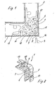
- a corner connector 1 shown in FIGS. 1 and 2 serves to connect two Miter cut hollow profiles 2 and 3, the corner connector with a Leg 4 inserted into the hollow profile 2 and a leg 5 in the hollow profile 3 is.
- the corner connector 1 is formed from an extruded aluminum profile and has a hollow chamber which is filled with a foamed material 6 is. It is also possible to cast the corner connector 1 from a solid material or made from a different material.
- the corner connector 1 has a channel 7 in the area of a miter plane 16 serves to distribute adhesive. Via an opening 8 in the hollow profile 3 Adhesive introduced through a filler neck 17, the groove 7 serving the adhesive in the area of the miter plane 16 around the corner connector 1 to distribute.
- the corner connector 1 has spacers 10 so that the Distribute adhesive between the hollow profiles 2 and 3 and the corner connector 1 can and provides a particularly stable connection.
- each leg 13 is provided, into each of which a pin 12 can be inserted. It is in the area of Recording 13 an opening 11 in the hollow profile 2 and 3, through which the Pen 12 can be inserted into the receptacle 13.
- the pin 12 is first inserted through an opening in the hollow profile 2 and moved into the receptacle 13 on the leg 4.
- a front projection 14th On the left in Fig. 3A of the Miter plane 16 side wall is a front projection 14th provided that protrudes like a strip into the receptacle 13.
- the pin 12 is therefore initially opposite a central plane 17 of the Recording 13 arranged slightly obliquely, with an axis 18 of the pin 12 around the Angle ⁇ is inclined from the center plane 17.
- the position is shown in FIG. 3C when the hollow profile 2 and the hollow profile 3 aligned aligned with the miter plane 16, with a certain preload is given by the pins 12.
- the pin 12 is at by the voltage assembling the opposite side of the corner connector 1 back into position pushed back in the axis of the pin 12 approximately with the middle plane the receptacle 13 is aligned.
- the projections 14 and 15 become elastic and / or plastically deformed, the hollow profile 2 against a prestress the miter plane 16 is pressed.
- the pin 12 is made of a hard Material, for example steel formed, which is harder than the material of the corner connector 1 is formed, which consists for example of aluminum.
- FIGS. 4A and 4B show a second exemplary embodiment of an inventive one Corner connector shown, the corner connector according to FIG. 1 only in Area of the recordings 13 is modified.
- a pin 12 is inserted into a receptacle 13 'on one Leg 4 'inserted, with an axis 20 of the pin 12 substantially perpendicular runs to the wall of the hollow profile 2. Also runs parallel to the pin 20 upper section 21 of a side wall of the receptacle 13 ', so that the pin 12 to can easily be inserted at the end of the upper section 21.
- the recording 13 ′ has a lower region, on which an inclines towards the upper section 21 extending lower section 22 is provided, which is at an angle ⁇ opposite the upper section 21 is inclined in the direction of the miter plane.
- the Angle ⁇ lies in a range between 0.2 ° and 10 °, preferably between 1 ° and 4 °, and is only shown somewhat larger for illustration in the figures.
- the pin 12 is driven into the lower portion 22 slanted, the opposite facing the miter plane 16 Side wall 23 arranged parallel to the wall of the lower section 22 is and thus forms a guide for the pin 12.
- Side wall 23 arranged parallel to the wall of the lower section 22 is and thus forms a guide for the pin 12.
- the hollow profile 2 in the direction of the miter planes 16 moved and biased.
- a counterforce through assembly a hollow profile on another leg of the corner connector is the Inclination of the pin 12 moved back slightly so that the pin 12 is jammed is held in the receptacle 13 '.
- the pin 12 is essentially only pivoted around a kink when inserting. It is also possible to use the Length two or more kinks or protrusions to provide the pin 12th to pivot in several smaller steps and thus also the hollow profile 2 to brace in smaller steps to the miter plane 16.
- the invention has been described for a corner connector with two legs. It is also possible the subject of the invention for a corner connector with a or use several legs, for example the corner connector can also be designed as a T-connector.
- the leg or legs can be in any Angles can be arranged to each other and it is possible to use one leg with the invention Fastening technology to a hollow profile and one another leg or another integrally formed connecting element with a other fastening technology on a hollow profile or another component set.
- a T-connector for example, usually only one leg is in a hollow profile is inserted and the foot of the T-connector is connected using other connecting means attached.
- the receptacle is in each case a groove formed, which extends over the entire width of the corner connector. It is also possible to design the recording in a different form, for example as Hole, hole or in the form of a recess.
- the means to tilt the instead of the strip-shaped projections, the pin can also be formed by other shapes Projections or recesses can be formed.
Landscapes
- Engineering & Computer Science (AREA)
- Civil Engineering (AREA)
- Structural Engineering (AREA)
- Mutual Connection Of Rods And Tubes (AREA)
- Connector Housings Or Holding Contact Members (AREA)
Abstract
Description
- Fig. 1
- eine geschnittene Draufsicht auf ein erstes Ausführungsbeispiel eines erfindungsgemäßen Eckverbinders im montierten Zustand;
- Fig. 2
- eine perspektivische Ansicht des Eckverbinders der Fig. 1;
- Fig. 3A - 3C
- eine Detailansicht des Bereichs einer Aufnahme des Eckverbinders der Fig. 1 bei der Montage, und
- Fig. 4A u. 4B
- eine Detailansicht des Bereichs einer Aufnahme eines Eckverbinders bei der Montage gemäß einem zweiten Ausfiihrungsbeispiel.
Claims (8)
- Eckverbinder (1) für auf Gehrung oder Stoß geschnittene Hohlprofile (2, 3) eines Rahmens, insbesondere für ein Fenster, eine Tür oder eine Fassade mit mindestens einem Schenkel (4, 5) zum Eingreifen in eine Kammer eines Hohlprofils, wobei an dem Schenkel mindestens eine Aufnahme (13) für einen Stift (12) zum kraftschlüssigen Verbinden der Hohlprofile vorgesehen ist, dadurch gekennzeichnet, dass in der Aufnahme (13, 13') Mittel zum Schrägstellen des Stiftes (12) in Richtung parallel zu der Stoß- oder Gehrungsebene (16) vorgesehen sind.
- Eckverbinder nach Anspruch 1, dadurch gekennzeichnet, dass die Aufnahme (13, 13') einen vorderen Abschnitt, in dem der Stift (12) in eine erste Richtung einfügbar ist, und einen hinteren Abschnitt aufweist, in dem der Stift (12) in eine zweite gegenüber der ersten Richtung zu der Stoß- oder Gehrungsebene (16) geneigte Richtung einfügbar ist.
- Eckverbinder nach Anspruch 1 oder 2, dadurch gekennzeichnet, dass der Winkel zwischen der ersten Richtung und der zweiten Richtung in einem Bereich zwischen 0,2° und 10°, vorzugsweise 1° bis 4° liegt.
- Eckverbinder nach einem der Ansprüche 1 bis 3, dadurch gekennzeichnet, dass die Aufnahmen (13, 13') jeweils durch eine Nut an einer Wand des Eckverbinders (1, 1') gebildet sind.
- Eckverbinder nach einem der Ansprüche 1 bis 4, dadurch gekennzeichnet, dass in der Aufnahme (13) an gegenüberliegenden Seitenwänden in der Höhe versetzt zueinander angeordnete Vorsprünge (14, 15) zur Führung des Stiftes (12) vorgesehen sind.
- Eckverbinder nach Anspruch 5, dadurch gekennzeichnet, dass die Vorsprünge (14, 15) jeweils von den Seitenwänden der Aufnahme (13) um 0,1 bis 1,0 mm hervorstehen.
- Eckverbinder nach einem der Ansprüche 1 bis 4, dadurch gekennzeichnet, dass die Aufnahme (13') jeweils winklig ausgebildet ist und eine Seitenwand aufweist, die einen vorderen Abschnitt (21) und einen hinteren Abschnitt (22) aufweist, die in einem Winkel zueinander angeordnet sind.
- Eckverbinder nach Anspruch 7, dadurch gekennzeichnet, dass die gegenüberliegende Seitenwand (23) der Aufnahme (13') sich parallel zu dem hinteren Abschnitt (22) erstreckt.
Applications Claiming Priority (2)
| Application Number | Priority Date | Filing Date | Title |
|---|---|---|---|
| DE20217295U DE20217295U1 (de) | 2002-11-09 | 2002-11-09 | Eckverbinder |
| DE20217295U | 2002-11-09 |
Publications (2)
| Publication Number | Publication Date |
|---|---|
| EP1452682A1 true EP1452682A1 (de) | 2004-09-01 |
| EP1452682B1 EP1452682B1 (de) | 2009-07-15 |
Family
ID=32038852
Family Applications (1)
| Application Number | Title | Priority Date | Filing Date |
|---|---|---|---|
| EP03025533A Expired - Lifetime EP1452682B1 (de) | 2002-11-09 | 2003-11-07 | Eckverbinder |
Country Status (4)
| Country | Link |
|---|---|
| EP (1) | EP1452682B1 (de) |
| DE (2) | DE20217295U1 (de) |
| DK (1) | DK1452682T3 (de) |
| ES (1) | ES2327623T3 (de) |
Citations (2)
| Publication number | Priority date | Publication date | Assignee | Title |
|---|---|---|---|---|
| DE2000439A1 (de) * | 1970-01-07 | 1971-07-15 | Manfred Muehle | Verbindungsvorrichtung fuer Rahmenteile |
| DE19539862A1 (de) * | 1995-10-26 | 1997-04-30 | Ekonal Bausysteme Gmbh & Co Kg | Eckverbindung mit Einsatzstücken in Hohlkammern von Profilstäben zur Bildung von Rahmenteilen |
Family Cites Families (4)
| Publication number | Priority date | Publication date | Assignee | Title |
|---|---|---|---|---|
| DE1957039U (de) * | 1966-10-21 | 1967-03-16 | Kaether & Co G M B H | Fensterrahmen. |
| DE7000294U (de) * | 1970-01-07 | 1970-05-14 | Muehle Manfred | Verbindungsvorrichtung fuer rahmenteile. |
| DE3726594A1 (de) * | 1987-08-10 | 1989-02-23 | Erbsloeh Julius & August | Eckverbindung fuer hohlprofil-rahmen |
| DE9321056U1 (de) * | 1993-02-10 | 1995-11-16 | Schüco International KG, 33609 Bielefeld | Eckverbindung auf Gehrung geschnittener Hohlprofile eines Rahmens für Fenster, Türen oder Fassaden |
-
2002
- 2002-11-09 DE DE20217295U patent/DE20217295U1/de not_active Expired - Lifetime
-
2003
- 2003-11-07 EP EP03025533A patent/EP1452682B1/de not_active Expired - Lifetime
- 2003-11-07 ES ES03025533T patent/ES2327623T3/es not_active Expired - Lifetime
- 2003-11-07 DK DK03025533T patent/DK1452682T3/da active
- 2003-11-07 DE DE50311707T patent/DE50311707D1/de not_active Expired - Lifetime
Patent Citations (3)
| Publication number | Priority date | Publication date | Assignee | Title |
|---|---|---|---|---|
| DE2000439A1 (de) * | 1970-01-07 | 1971-07-15 | Manfred Muehle | Verbindungsvorrichtung fuer Rahmenteile |
| DE2133344A1 (de) * | 1970-01-07 | 1973-01-25 | Manfred Muehle | Verbindungsvorrichtung fuer rahmenteile |
| DE19539862A1 (de) * | 1995-10-26 | 1997-04-30 | Ekonal Bausysteme Gmbh & Co Kg | Eckverbindung mit Einsatzstücken in Hohlkammern von Profilstäben zur Bildung von Rahmenteilen |
Also Published As
| Publication number | Publication date |
|---|---|
| DK1452682T3 (da) | 2009-10-19 |
| ES2327623T3 (es) | 2009-11-02 |
| EP1452682B1 (de) | 2009-07-15 |
| DE20217295U1 (de) | 2004-03-18 |
| DE50311707D1 (de) | 2009-08-27 |
Similar Documents
| Publication | Publication Date | Title |
|---|---|---|
| DE2633972A1 (de) | Verbindungsanordnung fuer moebel | |
| EP0136431A2 (de) | Konstruktion aus Profilstäben | |
| DE4429709C1 (de) | Verfahren zum Befestigen von Eckverbindern, vorzugsweise aus verschweißbarem Kunststoff, und Eckverbinder zur Verwendung bei einem solchen Verfahren | |
| DE20217301U1 (de) | Eckverbinder für auf Gehrung geschnittene Hohlprofile eines Rahmens | |
| DE19748613C1 (de) | Verbindungselement für Rahmenprofile | |
| EP1054130B1 (de) | Eckverbinder für Tür- oder Fenster-Hohlprofile | |
| DE9116873U1 (de) | Verbindungsvorrichtung für eine Sprossenkreuzkonstruktion | |
| DE4012808C2 (de) | Verbindungsformstück für Bauprofile | |
| DE19828382C2 (de) | Anordnung zum Befestigen eines einen Hohlquerschnitt aufweisenden Pfostens am Blendrahmen eines Fensters oder einer Türe aus Kunststoff oder Leichtmetall | |
| EP1035294B1 (de) | Kämpferverbinder-Satz | |
| EP1522668B1 (de) | Verbinder für Doppelfenster-Rahmenprofile | |
| EP1179652B1 (de) | Eckverbinder | |
| EP0067970B1 (de) | Befestigungsvorrichtung für Fassadenelemente an einer Gebäudeaussenwand | |
| DE2735825C2 (de) | ||
| DE3935717C1 (de) | ||
| DE602005003380T2 (de) | Verfahren zur Montage eines Verstärkungsteils auf die Frontplatte eines Kühl- oder Gefrierschrankes | |
| DE2627920A1 (de) | Eckverbindungswinkel fuer abstandshalteprofile eines mehrscheibenisolierglases | |
| EP1452682B1 (de) | Eckverbinder | |
| DE10008037A1 (de) | Fenster- oder Türrahmen mit einem Verbindungswinkel | |
| DE2802037A1 (de) | Vorrichtung zum zusammenhalten von an luftkanalabschnitten sitzenden verbindungsflanschen | |
| EP4355173B1 (de) | Verbindungsanordnung zur verbindung einer schubkastenwand mit einem schubkastenboden | |
| DE9201532U1 (de) | Geradverbinder für hohle Abstandsprofile von Mehrscheibenisoliergläsern | |
| DE202019103487U1 (de) | Spreizbarer Eckwinkel | |
| EP0004007B1 (de) | Verfahren zur Verbindung von rundgebogenen und geraden, hohlen Abstandsprofilen für Mehrscheibenisoliergläser | |
| DE102004043581A1 (de) | Bauteilesatz aus wenigstens einer Sprosse und wenigstens zwei Sprossenendstücken zum Einbauen in eine Isolierglasscheibe |
Legal Events
| Date | Code | Title | Description |
|---|---|---|---|
| PUAI | Public reference made under article 153(3) epc to a published international application that has entered the european phase |
Free format text: ORIGINAL CODE: 0009012 |
|
| AK | Designated contracting states |
Kind code of ref document: A1 Designated state(s): AT BE BG CH CY CZ DE DK EE ES FI FR GB GR HU IE IT LI LU MC NL PT RO SE SI SK TR |
|
| AX | Request for extension of the european patent |
Extension state: AL LT LV MK |
|
| 17P | Request for examination filed |
Effective date: 20050111 |
|
| 17Q | First examination report despatched |
Effective date: 20050222 |
|
| AKX | Designation fees paid |
Designated state(s): AT BE BG CH CY CZ DE DK EE ES FI FR GB GR HU IE IT LI LU MC NL PT RO SE SI SK TR |
|
| AXX | Extension fees paid |
Extension state: LT Payment date: 20050111 Extension state: LV Payment date: 20050111 |
|
| GRAP | Despatch of communication of intention to grant a patent |
Free format text: ORIGINAL CODE: EPIDOSNIGR1 |
|
| GRAS | Grant fee paid |
Free format text: ORIGINAL CODE: EPIDOSNIGR3 |
|
| GRAA | (expected) grant |
Free format text: ORIGINAL CODE: 0009210 |
|
| AK | Designated contracting states |
Kind code of ref document: B1 Designated state(s): AT BE BG CH CY CZ DE DK EE ES FI FR GB GR HU IE IT LI LU MC NL PT RO SE SI SK TR |
|
| AX | Request for extension of the european patent |
Extension state: LT LV |
|
| REG | Reference to a national code |
Ref country code: CH Ref legal event code: EP Ref country code: GB Ref legal event code: FG4D Free format text: NOT ENGLISH |
|
| REG | Reference to a national code |
Ref country code: CH Ref legal event code: NV Representative=s name: KATZAROV S.A. |
|
| REG | Reference to a national code |
Ref country code: IE Ref legal event code: FG4D |
|
| REF | Corresponds to: |
Ref document number: 50311707 Country of ref document: DE Date of ref document: 20090827 Kind code of ref document: P |
|
| REG | Reference to a national code |
Ref country code: DK Ref legal event code: T3 |
|
| REG | Reference to a national code |
Ref country code: ES Ref legal event code: FG2A Ref document number: 2327623 Country of ref document: ES Kind code of ref document: T3 |
|
| REG | Reference to a national code |
Ref country code: SE Ref legal event code: TRGR |
|
| LTIE | Lt: invalidation of european patent or patent extension |
Effective date: 20090715 |
|
| PG25 | Lapsed in a contracting state [announced via postgrant information from national office to epo] |
Ref country code: FI Free format text: LAPSE BECAUSE OF FAILURE TO SUBMIT A TRANSLATION OF THE DESCRIPTION OR TO PAY THE FEE WITHIN THE PRESCRIBED TIME-LIMIT Effective date: 20090715 |
|
| REG | Reference to a national code |
Ref country code: IE Ref legal event code: FD4D |
|
| PG25 | Lapsed in a contracting state [announced via postgrant information from national office to epo] |
Ref country code: SI Free format text: LAPSE BECAUSE OF FAILURE TO SUBMIT A TRANSLATION OF THE DESCRIPTION OR TO PAY THE FEE WITHIN THE PRESCRIBED TIME-LIMIT Effective date: 20090715 |
|
| PG25 | Lapsed in a contracting state [announced via postgrant information from national office to epo] |
Ref country code: BG Free format text: LAPSE BECAUSE OF FAILURE TO SUBMIT A TRANSLATION OF THE DESCRIPTION OR TO PAY THE FEE WITHIN THE PRESCRIBED TIME-LIMIT Effective date: 20091015 Ref country code: PT Free format text: LAPSE BECAUSE OF FAILURE TO SUBMIT A TRANSLATION OF THE DESCRIPTION OR TO PAY THE FEE WITHIN THE PRESCRIBED TIME-LIMIT Effective date: 20091115 |
|
| PG25 | Lapsed in a contracting state [announced via postgrant information from national office to epo] |
Ref country code: IE Free format text: LAPSE BECAUSE OF FAILURE TO SUBMIT A TRANSLATION OF THE DESCRIPTION OR TO PAY THE FEE WITHIN THE PRESCRIBED TIME-LIMIT Effective date: 20090715 Ref country code: RO Free format text: LAPSE BECAUSE OF FAILURE TO SUBMIT A TRANSLATION OF THE DESCRIPTION OR TO PAY THE FEE WITHIN THE PRESCRIBED TIME-LIMIT Effective date: 20090715 Ref country code: CZ Free format text: LAPSE BECAUSE OF FAILURE TO SUBMIT A TRANSLATION OF THE DESCRIPTION OR TO PAY THE FEE WITHIN THE PRESCRIBED TIME-LIMIT Effective date: 20090715 Ref country code: EE Free format text: LAPSE BECAUSE OF FAILURE TO SUBMIT A TRANSLATION OF THE DESCRIPTION OR TO PAY THE FEE WITHIN THE PRESCRIBED TIME-LIMIT Effective date: 20090715 |
|
| PLBE | No opposition filed within time limit |
Free format text: ORIGINAL CODE: 0009261 |
|
| STAA | Information on the status of an ep patent application or granted ep patent |
Free format text: STATUS: NO OPPOSITION FILED WITHIN TIME LIMIT |
|
| PG25 | Lapsed in a contracting state [announced via postgrant information from national office to epo] |
Ref country code: SK Free format text: LAPSE BECAUSE OF FAILURE TO SUBMIT A TRANSLATION OF THE DESCRIPTION OR TO PAY THE FEE WITHIN THE PRESCRIBED TIME-LIMIT Effective date: 20090715 |
|
| 26N | No opposition filed |
Effective date: 20100416 |
|
| PG25 | Lapsed in a contracting state [announced via postgrant information from national office to epo] |
Ref country code: MC Free format text: LAPSE BECAUSE OF NON-PAYMENT OF DUE FEES Effective date: 20091130 |
|
| PG25 | Lapsed in a contracting state [announced via postgrant information from national office to epo] |
Ref country code: GR Free format text: LAPSE BECAUSE OF FAILURE TO SUBMIT A TRANSLATION OF THE DESCRIPTION OR TO PAY THE FEE WITHIN THE PRESCRIBED TIME-LIMIT Effective date: 20091016 |
|
| PG25 | Lapsed in a contracting state [announced via postgrant information from national office to epo] |
Ref country code: LU Free format text: LAPSE BECAUSE OF NON-PAYMENT OF DUE FEES Effective date: 20091107 |
|
| PG25 | Lapsed in a contracting state [announced via postgrant information from national office to epo] |
Ref country code: HU Free format text: LAPSE BECAUSE OF FAILURE TO SUBMIT A TRANSLATION OF THE DESCRIPTION OR TO PAY THE FEE WITHIN THE PRESCRIBED TIME-LIMIT Effective date: 20100116 |
|
| PG25 | Lapsed in a contracting state [announced via postgrant information from national office to epo] |
Ref country code: TR Free format text: LAPSE BECAUSE OF FAILURE TO SUBMIT A TRANSLATION OF THE DESCRIPTION OR TO PAY THE FEE WITHIN THE PRESCRIBED TIME-LIMIT Effective date: 20090715 |
|
| PG25 | Lapsed in a contracting state [announced via postgrant information from national office to epo] |
Ref country code: CY Free format text: LAPSE BECAUSE OF FAILURE TO SUBMIT A TRANSLATION OF THE DESCRIPTION OR TO PAY THE FEE WITHIN THE PRESCRIBED TIME-LIMIT Effective date: 20090715 |
|
| PGFP | Annual fee paid to national office [announced via postgrant information from national office to epo] |
Ref country code: DK Payment date: 20121126 Year of fee payment: 10 |
|
| PGFP | Annual fee paid to national office [announced via postgrant information from national office to epo] |
Ref country code: SE Payment date: 20121122 Year of fee payment: 10 |
|
| REG | Reference to a national code |
Ref country code: DK Ref legal event code: EBP Effective date: 20131130 |
|
| REG | Reference to a national code |
Ref country code: SE Ref legal event code: EUG |
|
| PG25 | Lapsed in a contracting state [announced via postgrant information from national office to epo] |
Ref country code: SE Free format text: LAPSE BECAUSE OF NON-PAYMENT OF DUE FEES Effective date: 20131108 |
|
| PG25 | Lapsed in a contracting state [announced via postgrant information from national office to epo] |
Ref country code: DK Free format text: LAPSE BECAUSE OF NON-PAYMENT OF DUE FEES Effective date: 20131130 |
|
| REG | Reference to a national code |
Ref country code: FR Ref legal event code: PLFP Year of fee payment: 13 |
|
| REG | Reference to a national code |
Ref country code: FR Ref legal event code: PLFP Year of fee payment: 14 |
|
| REG | Reference to a national code |
Ref country code: FR Ref legal event code: PLFP Year of fee payment: 15 |
|
| REG | Reference to a national code |
Ref country code: CH Ref legal event code: PCAR Free format text: NEW ADDRESS: AVENUE DES MORGINES 12, 1213 PETIT-LANCY (CH) |
|
| PGFP | Annual fee paid to national office [announced via postgrant information from national office to epo] |
Ref country code: NL Payment date: 20181122 Year of fee payment: 16 |
|
| REG | Reference to a national code |
Ref country code: CH Ref legal event code: PL |
|
| REG | Reference to a national code |
Ref country code: NL Ref legal event code: MM Effective date: 20191201 |
|
| PG25 | Lapsed in a contracting state [announced via postgrant information from national office to epo] |
Ref country code: CH Free format text: LAPSE BECAUSE OF NON-PAYMENT OF DUE FEES Effective date: 20191130 Ref country code: LI Free format text: LAPSE BECAUSE OF NON-PAYMENT OF DUE FEES Effective date: 20191130 |
|
| REG | Reference to a national code |
Ref country code: AT Ref legal event code: MM01 Ref document number: 436633 Country of ref document: AT Kind code of ref document: T Effective date: 20191107 |
|
| PG25 | Lapsed in a contracting state [announced via postgrant information from national office to epo] |
Ref country code: NL Free format text: LAPSE BECAUSE OF NON-PAYMENT OF DUE FEES Effective date: 20191201 |
|
| PG25 | Lapsed in a contracting state [announced via postgrant information from national office to epo] |
Ref country code: AT Free format text: LAPSE BECAUSE OF NON-PAYMENT OF DUE FEES Effective date: 20191107 |
|
| PGFP | Annual fee paid to national office [announced via postgrant information from national office to epo] |
Ref country code: FR Payment date: 20201022 Year of fee payment: 18 Ref country code: GB Payment date: 20201022 Year of fee payment: 18 Ref country code: IT Payment date: 20201130 Year of fee payment: 18 Ref country code: ES Payment date: 20201207 Year of fee payment: 18 |
|
| PGFP | Annual fee paid to national office [announced via postgrant information from national office to epo] |
Ref country code: BE Payment date: 20201026 Year of fee payment: 18 |
|
| PGFP | Annual fee paid to national office [announced via postgrant information from national office to epo] |
Ref country code: DE Payment date: 20201218 Year of fee payment: 18 |
|
| REG | Reference to a national code |
Ref country code: DE Ref legal event code: R119 Ref document number: 50311707 Country of ref document: DE |
|
| GBPC | Gb: european patent ceased through non-payment of renewal fee |
Effective date: 20211107 |
|
| PG25 | Lapsed in a contracting state [announced via postgrant information from national office to epo] |
Ref country code: BE Free format text: LAPSE BECAUSE OF NON-PAYMENT OF DUE FEES Effective date: 20211130 |
|
| REG | Reference to a national code |
Ref country code: BE Ref legal event code: MM Effective date: 20211130 |
|
| PG25 | Lapsed in a contracting state [announced via postgrant information from national office to epo] |
Ref country code: GB Free format text: LAPSE BECAUSE OF NON-PAYMENT OF DUE FEES Effective date: 20211107 Ref country code: DE Free format text: LAPSE BECAUSE OF NON-PAYMENT OF DUE FEES Effective date: 20220601 |
|
| PG25 | Lapsed in a contracting state [announced via postgrant information from national office to epo] |
Ref country code: FR Free format text: LAPSE BECAUSE OF NON-PAYMENT OF DUE FEES Effective date: 20211130 |
|
| PG25 | Lapsed in a contracting state [announced via postgrant information from national office to epo] |
Ref country code: IT Free format text: LAPSE BECAUSE OF NON-PAYMENT OF DUE FEES Effective date: 20211107 |
|
| REG | Reference to a national code |
Ref country code: ES Ref legal event code: FD2A Effective date: 20230207 |
|
| PG25 | Lapsed in a contracting state [announced via postgrant information from national office to epo] |
Ref country code: ES Free format text: LAPSE BECAUSE OF NON-PAYMENT OF DUE FEES Effective date: 20211108 |