EP1451507B1 - Roof truss with structually integrated solar collector - Google Patents
Roof truss with structually integrated solar collector Download PDFInfo
- Publication number
- EP1451507B1 EP1451507B1 EP02783993.5A EP02783993A EP1451507B1 EP 1451507 B1 EP1451507 B1 EP 1451507B1 EP 02783993 A EP02783993 A EP 02783993A EP 1451507 B1 EP1451507 B1 EP 1451507B1
- Authority
- EP
- European Patent Office
- Prior art keywords
- roof
- air
- channel
- truss
- light
- Prior art date
- Legal status (The legal status is an assumption and is not a legal conclusion. Google has not performed a legal analysis and makes no representation as to the accuracy of the status listed.)
- Expired - Lifetime
Links
- 230000005611 electricity Effects 0.000 claims description 16
- 239000000463 material Substances 0.000 claims description 9
- XLYOFNOQVPJJNP-UHFFFAOYSA-N water Substances O XLYOFNOQVPJJNP-UHFFFAOYSA-N 0.000 claims description 6
- 238000010438 heat treatment Methods 0.000 description 16
- 229910052751 metal Inorganic materials 0.000 description 11
- 239000002184 metal Substances 0.000 description 11
- 238000005286 illumination Methods 0.000 description 9
- 238000005253 cladding Methods 0.000 description 7
- 238000010276 construction Methods 0.000 description 5
- 238000004519 manufacturing process Methods 0.000 description 4
- 238000000034 method Methods 0.000 description 4
- 238000009423 ventilation Methods 0.000 description 4
- 238000006243 chemical reaction Methods 0.000 description 3
- 238000001816 cooling Methods 0.000 description 3
- 238000009826 distribution Methods 0.000 description 3
- 238000005516 engineering process Methods 0.000 description 3
- 229910000831 Steel Inorganic materials 0.000 description 2
- 238000010521 absorption reaction Methods 0.000 description 2
- 229910052782 aluminium Inorganic materials 0.000 description 2
- XAGFODPZIPBFFR-UHFFFAOYSA-N aluminium Chemical compound [Al] XAGFODPZIPBFFR-UHFFFAOYSA-N 0.000 description 2
- 238000013459 approach Methods 0.000 description 2
- 230000000694 effects Effects 0.000 description 2
- 239000011521 glass Substances 0.000 description 2
- 239000010959 steel Substances 0.000 description 2
- 239000011269 tar Substances 0.000 description 2
- 239000012780 transparent material Substances 0.000 description 2
- 239000002023 wood Substances 0.000 description 2
- 238000003491 array Methods 0.000 description 1
- 238000009435 building construction Methods 0.000 description 1
- 239000004567 concrete Substances 0.000 description 1
- 230000003750 conditioning effect Effects 0.000 description 1
- 230000008602 contraction Effects 0.000 description 1
- 238000005265 energy consumption Methods 0.000 description 1
- 238000003306 harvesting Methods 0.000 description 1
- 238000009413 insulation Methods 0.000 description 1
- 239000012528 membrane Substances 0.000 description 1
- 150000002739 metals Chemical class 0.000 description 1
- 230000005855 radiation Effects 0.000 description 1
- 238000007789 sealing Methods 0.000 description 1
- 230000001932 seasonal effect Effects 0.000 description 1
- 239000007787 solid Substances 0.000 description 1
- 239000000758 substrate Substances 0.000 description 1
- 239000011270 tar paper Substances 0.000 description 1
- 238000013022 venting Methods 0.000 description 1
Images


Classifications
-
- H—ELECTRICITY
- H02—GENERATION; CONVERSION OR DISTRIBUTION OF ELECTRIC POWER
- H02S—GENERATION OF ELECTRIC POWER BY CONVERSION OF INFRARED RADIATION, VISIBLE LIGHT OR ULTRAVIOLET LIGHT, e.g. USING PHOTOVOLTAIC [PV] MODULES
- H02S40/00—Components or accessories in combination with PV modules, not provided for in groups H02S10/00 - H02S30/00
- H02S40/40—Thermal components
- H02S40/44—Means to utilise heat energy, e.g. hybrid systems producing warm water and electricity at the same time
-
- F—MECHANICAL ENGINEERING; LIGHTING; HEATING; WEAPONS; BLASTING
- F24—HEATING; RANGES; VENTILATING
- F24S—SOLAR HEAT COLLECTORS; SOLAR HEAT SYSTEMS
- F24S10/00—Solar heat collectors using working fluids
- F24S10/25—Solar heat collectors using working fluids having two or more passages for the same working fluid layered in direction of solar-rays, e.g. having upper circulation channels connected with lower circulation channels
-
- F—MECHANICAL ENGINEERING; LIGHTING; HEATING; WEAPONS; BLASTING
- F24—HEATING; RANGES; VENTILATING
- F24S—SOLAR HEAT COLLECTORS; SOLAR HEAT SYSTEMS
- F24S20/00—Solar heat collectors specially adapted for particular uses or environments
- F24S20/60—Solar heat collectors integrated in fixed constructions, e.g. in buildings
- F24S20/66—Solar heat collectors integrated in fixed constructions, e.g. in buildings in the form of facade constructions, e.g. wall constructions
-
- F—MECHANICAL ENGINEERING; LIGHTING; HEATING; WEAPONS; BLASTING
- F24—HEATING; RANGES; VENTILATING
- F24S—SOLAR HEAT COLLECTORS; SOLAR HEAT SYSTEMS
- F24S20/00—Solar heat collectors specially adapted for particular uses or environments
- F24S20/60—Solar heat collectors integrated in fixed constructions, e.g. in buildings
- F24S20/67—Solar heat collectors integrated in fixed constructions, e.g. in buildings in the form of roof constructions
-
- H—ELECTRICITY
- H02—GENERATION; CONVERSION OR DISTRIBUTION OF ELECTRIC POWER
- H02S—GENERATION OF ELECTRIC POWER BY CONVERSION OF INFRARED RADIATION, VISIBLE LIGHT OR ULTRAVIOLET LIGHT, e.g. USING PHOTOVOLTAIC [PV] MODULES
- H02S20/00—Supporting structures for PV modules
- H02S20/20—Supporting structures directly fixed to an immovable object
- H02S20/22—Supporting structures directly fixed to an immovable object specially adapted for buildings
- H02S20/23—Supporting structures directly fixed to an immovable object specially adapted for buildings specially adapted for roof structures
-
- Y—GENERAL TAGGING OF NEW TECHNOLOGICAL DEVELOPMENTS; GENERAL TAGGING OF CROSS-SECTIONAL TECHNOLOGIES SPANNING OVER SEVERAL SECTIONS OF THE IPC; TECHNICAL SUBJECTS COVERED BY FORMER USPC CROSS-REFERENCE ART COLLECTIONS [XRACs] AND DIGESTS
- Y02—TECHNOLOGIES OR APPLICATIONS FOR MITIGATION OR ADAPTATION AGAINST CLIMATE CHANGE
- Y02A—TECHNOLOGIES FOR ADAPTATION TO CLIMATE CHANGE
- Y02A30/00—Adapting or protecting infrastructure or their operation
- Y02A30/60—Planning or developing urban green infrastructure
-
- Y—GENERAL TAGGING OF NEW TECHNOLOGICAL DEVELOPMENTS; GENERAL TAGGING OF CROSS-SECTIONAL TECHNOLOGIES SPANNING OVER SEVERAL SECTIONS OF THE IPC; TECHNICAL SUBJECTS COVERED BY FORMER USPC CROSS-REFERENCE ART COLLECTIONS [XRACs] AND DIGESTS
- Y02—TECHNOLOGIES OR APPLICATIONS FOR MITIGATION OR ADAPTATION AGAINST CLIMATE CHANGE
- Y02B—CLIMATE CHANGE MITIGATION TECHNOLOGIES RELATED TO BUILDINGS, e.g. HOUSING, HOUSE APPLIANCES OR RELATED END-USER APPLICATIONS
- Y02B10/00—Integration of renewable energy sources in buildings
- Y02B10/10—Photovoltaic [PV]
-
- Y—GENERAL TAGGING OF NEW TECHNOLOGICAL DEVELOPMENTS; GENERAL TAGGING OF CROSS-SECTIONAL TECHNOLOGIES SPANNING OVER SEVERAL SECTIONS OF THE IPC; TECHNICAL SUBJECTS COVERED BY FORMER USPC CROSS-REFERENCE ART COLLECTIONS [XRACs] AND DIGESTS
- Y02—TECHNOLOGIES OR APPLICATIONS FOR MITIGATION OR ADAPTATION AGAINST CLIMATE CHANGE
- Y02B—CLIMATE CHANGE MITIGATION TECHNOLOGIES RELATED TO BUILDINGS, e.g. HOUSING, HOUSE APPLIANCES OR RELATED END-USER APPLICATIONS
- Y02B10/00—Integration of renewable energy sources in buildings
- Y02B10/20—Solar thermal
-
- Y—GENERAL TAGGING OF NEW TECHNOLOGICAL DEVELOPMENTS; GENERAL TAGGING OF CROSS-SECTIONAL TECHNOLOGIES SPANNING OVER SEVERAL SECTIONS OF THE IPC; TECHNICAL SUBJECTS COVERED BY FORMER USPC CROSS-REFERENCE ART COLLECTIONS [XRACs] AND DIGESTS
- Y02—TECHNOLOGIES OR APPLICATIONS FOR MITIGATION OR ADAPTATION AGAINST CLIMATE CHANGE
- Y02B—CLIMATE CHANGE MITIGATION TECHNOLOGIES RELATED TO BUILDINGS, e.g. HOUSING, HOUSE APPLIANCES OR RELATED END-USER APPLICATIONS
- Y02B10/00—Integration of renewable energy sources in buildings
- Y02B10/70—Hybrid systems, e.g. uninterruptible or back-up power supplies integrating renewable energies
-
- Y—GENERAL TAGGING OF NEW TECHNOLOGICAL DEVELOPMENTS; GENERAL TAGGING OF CROSS-SECTIONAL TECHNOLOGIES SPANNING OVER SEVERAL SECTIONS OF THE IPC; TECHNICAL SUBJECTS COVERED BY FORMER USPC CROSS-REFERENCE ART COLLECTIONS [XRACs] AND DIGESTS
- Y02—TECHNOLOGIES OR APPLICATIONS FOR MITIGATION OR ADAPTATION AGAINST CLIMATE CHANGE
- Y02E—REDUCTION OF GREENHOUSE GAS [GHG] EMISSIONS, RELATED TO ENERGY GENERATION, TRANSMISSION OR DISTRIBUTION
- Y02E10/00—Energy generation through renewable energy sources
- Y02E10/40—Solar thermal energy, e.g. solar towers
- Y02E10/44—Heat exchange systems
-
- Y—GENERAL TAGGING OF NEW TECHNOLOGICAL DEVELOPMENTS; GENERAL TAGGING OF CROSS-SECTIONAL TECHNOLOGIES SPANNING OVER SEVERAL SECTIONS OF THE IPC; TECHNICAL SUBJECTS COVERED BY FORMER USPC CROSS-REFERENCE ART COLLECTIONS [XRACs] AND DIGESTS
- Y02—TECHNOLOGIES OR APPLICATIONS FOR MITIGATION OR ADAPTATION AGAINST CLIMATE CHANGE
- Y02E—REDUCTION OF GREENHOUSE GAS [GHG] EMISSIONS, RELATED TO ENERGY GENERATION, TRANSMISSION OR DISTRIBUTION
- Y02E10/00—Energy generation through renewable energy sources
- Y02E10/50—Photovoltaic [PV] energy
-
- Y—GENERAL TAGGING OF NEW TECHNOLOGICAL DEVELOPMENTS; GENERAL TAGGING OF CROSS-SECTIONAL TECHNOLOGIES SPANNING OVER SEVERAL SECTIONS OF THE IPC; TECHNICAL SUBJECTS COVERED BY FORMER USPC CROSS-REFERENCE ART COLLECTIONS [XRACs] AND DIGESTS
- Y02—TECHNOLOGIES OR APPLICATIONS FOR MITIGATION OR ADAPTATION AGAINST CLIMATE CHANGE
- Y02E—REDUCTION OF GREENHOUSE GAS [GHG] EMISSIONS, RELATED TO ENERGY GENERATION, TRANSMISSION OR DISTRIBUTION
- Y02E10/00—Energy generation through renewable energy sources
- Y02E10/60—Thermal-PV hybrids
Definitions
- the present invention relates to building construction and the placement of solar energy collectors thereon. More specifically, the present invention relates to integrating solar collectors with building components so as to permit the simultaneous solar harvesting of heat and light, the conversion thereof to electrical energy, and the selective use of heat for heating and cooling.
- a roof typically comprises a layer of impermeable tar, tarpaper or concrete laid over a wood or metal platform (deck) of corrugated metal sheeting. While a roof seals a building from the environment, it also results in substantially reduced daylight illumination, the loss of a heat source in cool seasons and the collection of heat in warm seasons. Skylights may or not be fitted to improve illumination but may add to the heat gain in the warmer months. Similarly, wall construction is primarily a means of sealing out the elements from the inside of a structure.
- Solar energy is tantalizing in both its promise and its evasiveness.
- the ultimate objective is to utilize solar energy to heat, cool, provide electricity, and light structures efficiently and to reduce the need for energy from other sources.
- Various approaches have been suggested for achieving each of elements of this objective.
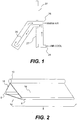
- the "Minnesota window heater” is illustrated. This unit is placed in a window 27. The suns rays are absorbed on a black (or dark)) panel 25 heating the air in the vicinity of the panel. The air rises through the heater (as noted by the arrows, causing more cool air to be drawn into the heater through opening 24. Heated air is expelled through opening 26 into the room.
- solar photovoltaic panels may be laid horizontally or framed to sit at an angle.
- photovoltaic (amorphous) on plastic substrate is available to lay in pans of standing seam metallic roofing. While photovoltaic panels permit the production of electricity, the per-kilowatt cost of generation is high. Additionally, the panels block solar illumination of the structure thereby trading off one form of solar energy for another.
- the SOLARWALL ® Solar Heating System made by conserveal Engineering (Conserval Engineering) heats air in the winter.
- a southern wall is metal clad (aluminum or steel) on its exterior.
- a cavity is formed between the building's southern wall and the metal cladding.
- a ventilation fan positioned at the top of the cavity creates reduced pressure within the cavity. Outside air is drawn in through holes in the metal cladding due to air pressure differential.
- the dark colored cladding is heated by solar radiation.
- the external air that is drawn over the metal cladding is heated and captured by openings in the metal cladding and collected in the wall cavity.
- the warmed air from the wall cavity rises to a plenum at the top of the cavity and is ducted to a circulation fan.
- the warmed air is circulated throughout the building.
- Applications include using the metal cladding as roofing material and overlaying the metal cladding with photovoltaic panels to produce electricity.
- U.S. Patent 4,466,424 issued to Lockwood and entitled “Solar Collector System For Standing Seam Roofs,” ('424) describes a solar collector system incorporated into a standing seam roof.
- the collector is formed by securing two transparent sheets to the standing seams of a roof panel to form two channels, one acting as a heat exchanger and the other an insulating chamber.
- Sun light impinges on the bottom of the roof panel and heats it. Air travels over the heated surface of the bottom of the roof panel and is heated and collected by ductwork located near the center ridge of the roof.
- French Patent 2,621,943 was issued to Hernecq for a heat collection system in the attic of a home for distribution throughout the home.
- An embodiment of the present invention is a roof component that integrates a solar collector into the structure of the roof itself.
- a combined solar collector is built into two sides of an integrated truss collector structure, in lieu of a built up platform of roof decking and tar, etc.
- This truss structure rests upon the load bearing walls, apex up, orienting panels to the south and panels the north.
- the southerly facing solar energy collection panels collect solar energy for conversion to heat and/or electricity.
- the northerly facing sunlight collection panels (daylighter panels) collect light for illumination of the interior of an enclosed structure.
- An embodiment of the present invention is a roof structure that integrates solar collectors into the structure of the roof itself.
- a cross section of an integrated truss collector 8 which could be also just called integrated truss is illustrated.
- the integrated truss collector 8 illustrated comprises two lower rails 6 , a cross member 12 , a truss air duct 10 , solar energy collection panel 16 which could be also just called solar energy collector and daylighter panel 18 which could be also called light collector.
- the solar energy collection panel 16 is oriented in a southerly direction and the daylighter panels 18 are oriented in a northerly direction.
- Each end of the integrated truss collector 8 is supported by a weight-bearing structure.
- the integrated truss collector 8 comprises a single panel length, however this is not meant as a limitation. As would be apparent to those skilled in the art of the present invention, the number of panels may be determined by the producer of the integrated truss collector 8, subject to limitations of structural strength and loading. Additionally, integrated truss collector 8 may comprise supporting structures in addition to the lower rails 6 and, cross member 12, which supporting structures would be apparent to those skilled in the art of the present invention. Additionally, truss air duct 10, which as will be described in detail below receives heated air from solar energy collection panel 16, is illustrated as tubular in cross section. However, this is not intended as a limitation. Other means of receiving heated air from solar energy collection panel 16 may be used without departing from the scope of the present invention. For example, in an embodiment of the present invention, the truss air duct 10 is integrated with the solar energy collection panel 16.
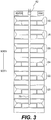
- the integrated truss collectors 20, 22, 24, 26, 28, 30 are generally oriented east-west with the sloped portions facing south for collecting solar energy and north for collecting light for illumination.
- a roof air duct 76 for collecting and distributing warm air runs in a north-south direction above the trusses 20, 22, 24, 26, 28, 30.
- the roof air duct 76 connects to each of the roof trusses at the truss air duct 10 (illustrated in Figure 2 and 4 ).
- This roof air duct 76 may be steel, aluminum or other suitable material, including entirely or partially transparent material to allow further air heating.
- the roof air duct 76 may extend all the way to the south side of the roof, if a "South Wall" (described below) is fitted to the south face of the structure.
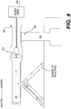
- warm collected from each of the integrated truss collectors is used in an electrical generator 82 to generate electricity for building use or/and distribution to an electrical grid.
- the electrical generator 82 comprises a low-pressure turbine 83 that is turned by the warm air flowing through the roof air duct 76.
- the low-pressure turbine 83 in turn drives an electrical generator 82.
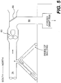
- a louver 86 illustrated in the closed position or similar device directs the hot air exhaust to chimney 88 for venting into the atmosphere.
- louver 86 is open to direct warm air into the internal structure through vent 90.
- Low-pressure turbine 83 is not configured to produce electricity in this embodiment.
- daylighter panel 30 which could be also called light collector.
- solar energy collection panel 40 which could be also called light collector.
- the daylighter panel 30 comprises outer glazing 32 and inner glazing 34, however this is not meant as a limitation. Additional glazing may be used without departing from the scope of the present invention.
- Outer glazing 32 and inner glazing 34 form channel 58 that directs air from the daylighter panel 30 to solar energy collection panel 40.
- the daylighter panel 30 allows daylight to enter the structure to illuminate the spaces within.
- the daylighter panel 30 is vented to draw inside air 36 from intake vent 38 (located in proximity to bottom rail 6) and to vent the air to solar energy collection panel 40 via the first air gap 72 located below and external to the truss air duct 10.
- air intake vent 38 would be located near the apex of the triangular cross-section of the integrated truss collector.
- a second channel would be formed in daylighter panel 30 (not illustrated) and the air would flow down this second channel to channel 58 before flowing to the solar energy collection panel 40 as previously described.
- Solar energy collection panel 40 comprises a single transparent layer 42 comprising glass, plastic or other transparent material that allows the sun to illuminate a light-absorbing layer 44.
- a daylighter panel 30 and a solar energy collection panel 40 are deployed as described in reference to Figure 6 with the exception that light-absorbing layer 44 is a photovoltaic (PV) material that absorbs solar energy to produce electricity. Solar energy not converted to electricity is converted to heat that is collected as described below.
- PV photovoltaic
- light-absorbing layer 44 is a rigid material that is optimized for heat absorption.
- light-absorbing layer 44 is a metal or wood sheet that is painted black.
- a bottom or inner layer 46 is solid, with an optionally silvered interior to enhance the reflectance characteristics from daylighter panel 30.
- the three layers of solar energy collection panel 40 form two channels, channels 60 and 62.
- sunlight passes through the transparent panel 42 of the solar energy collection panel 40 and is absorbed by light-absorbing layer 44.
- the air within the first channel 60 is heated it expands, rises and induces a movement toward the top of the truss. This in turn causes air to move through the second channel 62 downward through an opening 64 which could be also called connection path in the light-absorbing layer 44 to be heated by the absorption panel.
- Air is drawn to the solar energy collection panel 40 through first air gap 72 in the daylighter panel 30 on the north-facing surface. Relatively cool inside air 36 is drawn into a third channel 58 though intake vent 38.
- Air that is drawn into the system of the present invention travels through the third channel 58, which is connected to the second 62.
- a low pressure region formed by the heated air of the solar energy collection panel 40, causes air to be transported through channels 58 and 62 from the daylighter panel 30 to the solar energy collection panel 40 through opening 64 at the bottom of the south facing solar energy collection panel 40.
- the heated air is then accumulated at truss air duct 10.
- Heated air is then collected from a plurality of integrated truss collectors 8 by roof air duct 76 through collection vents 78 which could be also called second air gap in each of the plurality of truss air ducts 10. Heated air travels to the roof air duct 76 through channel 80.
- inside air 36 is drawn into the previously described channels, heated and distributed for return to the internal structure.
- warm air is from the roof through bypass 70 located on the solar energy collection panel 40 near lower rail 6. This avoids removing all the cool air from inside the building during hot weather.
- bypass 70 is opened or closed by the use of a bimetal hinge.
- the two metals of the hinge have differing expansion and contraction coefficients. It is the greater heat of summer time that opens the bypass. This is not meant as a limitation however.
- bypass 70 may be mechanically or electrically actuated by a thermostat or other heat
- the heated air from the roof air duct 76 is directed to a heat exchanger where the heated air is used for hot water production.
- the heated air is used to operate a low-pressure turbine that in turn drives an electrical generator to produce electricity.
- light-absorbing layer 44 comprises a PV panel. Electricity from the PV panel and from the electrical generator (see Figure 4 ), feed into the structure's electrical system for dedicated internal load, with heavy amperage leads inside the structure dedicated to the external utility grid.
Landscapes
- Engineering & Computer Science (AREA)
- Thermal Sciences (AREA)
- Chemical & Material Sciences (AREA)
- General Engineering & Computer Science (AREA)
- Physics & Mathematics (AREA)
- Life Sciences & Earth Sciences (AREA)
- Sustainable Development (AREA)
- Mechanical Engineering (AREA)
- Combustion & Propulsion (AREA)
- Sustainable Energy (AREA)
- Architecture (AREA)
- Civil Engineering (AREA)
- Structural Engineering (AREA)
- Roof Covering Using Slabs Or Stiff Sheets (AREA)
- Building Environments (AREA)
- Photovoltaic Devices (AREA)
Description
- The present invention relates to building construction and the placement of solar energy collectors thereon. More specifically, the present invention relates to integrating solar collectors with building components so as to permit the simultaneous solar harvesting of heat and light, the conversion thereof to electrical energy, and the selective use of heat for heating and cooling.
- Traditional roof technologies construct elevated covers to buildings. A roof typically comprises a layer of impermeable tar, tarpaper or concrete laid over a wood or metal platform (deck) of corrugated metal sheeting. While a roof seals a building from the environment, it also results in substantially reduced daylight illumination, the loss of a heat source in cool seasons and the collection of heat in warm seasons. Skylights may or not be fitted to improve illumination but may add to the heat gain in the warmer months. Similarly, wall construction is primarily a means of sealing out the elements from the inside of a structure.
- Solar energy is tantalizing in both its promise and its evasiveness. The ultimate objective is to utilize solar energy to heat, cool, provide electricity, and light structures efficiently and to reduce the need for energy from other sources. Various approaches have been suggested for achieving each of elements of this objective.
- In a "German Roof" a series of windows are present on the roof of a building. In cross section these appear as a saw tooth pattern on the roof. They provide both light and heat (but usually only when they face the sun).
- Referring to
Figure 1 , the "Minnesota window heater" is illustrated. This unit is placed in awindow 27. The suns rays are absorbed on a black (or dark))panel 25 heating the air in the vicinity of the panel. The air rises through the heater (as noted by the arrows, causing more cool air to be drawn into the heater through opening 24. Heated air is expelled through opening 26 into the room. - Technologies that collect some aspect of solar energy introduce some negative side effects that require energy consumption to offset. Solar heat exchangers for water and space heating or for electrical energy collection cause a build up of heat in summer months. This heat needs to be actively dissipated or mechanically cooled at an expense. Similarly, solar technologies that are designed to heat water and convert solar energy to electrical energy ignore winter heating needs. Skylights and solar daylighters provide illumination but just as often add heat (via direct sunlight) as fast as illumination and increase the "solar oven" effect of most buildings.
- At additional expense and effort, solar photovoltaic panels may be laid horizontally or framed to sit at an angle. For example, photovoltaic (amorphous) on plastic substrate is available to lay in pans of standing seam metallic roofing. While photovoltaic panels permit the production of electricity, the per-kilowatt cost of generation is high. Additionally, the panels block solar illumination of the structure thereby trading off one form of solar energy for another.
- "The SOLARWALL® Solar Heating System" made by Conserval Engineering (Conserval Engineering) heats air in the winter. A southern wall is metal clad (aluminum or steel) on its exterior. A cavity is formed between the building's southern wall and the metal cladding. A ventilation fan, positioned at the top of the cavity creates reduced pressure within the cavity. Outside air is drawn in through holes in the metal cladding due to air pressure differential. The dark colored cladding is heated by solar radiation. The external air that is drawn over the metal cladding is heated and captured by openings in the metal cladding and collected in the wall cavity. The warmed air from the wall cavity rises to a plenum at the top of the cavity and is ducted to a circulation fan. The warmed air is circulated throughout the building. Applications include using the metal cladding as roofing material and overlaying the metal cladding with photovoltaic panels to produce electricity.
- The Conserval Engineering approach, described above, is also described in
U.S. Patent 4,899,728 to Peter et. al , entiled "Method and Apparatus for Preheating Ventilation Air for a Building", ('728) andU.S. Patent 4,934,338 to Hollick et. al , entitle, "Method and Apparatus for Preheating Ventilation Air for a Building", ('338). The description for patents '338 and '728 are virtually the same (the '338 patent is a divisional of the '728 patent). Effectively, both citations are for an exterior wall passive solar heat collector for heating outside air. - In
Canadian Patent 1,196,825 issued to Hollick and entitled "Method for Preheating Ventilation Air in a Building" ('825), describes an outer transparent glazing to a south wall that allows solar energy to penetrate the glazing material (glass, plastic or the like) and be absorbed on a black painted building wall. There is a space between the glazing material and the building wall forming an air chamber. Outside air is drawn into the air chamber through an opening at the bottom of the glazed material. The air is heated by the building wall which has become heated from absorbing solar energy. The air rises and is distributed by fan and duct work through the building for heating purposes. If heating is not desired, the hot air is allowed to vent to the outside. - In
U.S. Patent 4,449,347 issued to Rooney and entitled "Solar Collection Building Truss," ('347) describes a solar collector integrated into a building truss that can be fabricated at a building site or pre-fabricated at a factory. The '347 patent teaches use of reflective surfaces to direct light to a heat absorbing member connected to a heat exchanger or other means for storing heat generated by the heat absorbing member. A similar truss was described inU.S. Patent 4,237,869 also issued to Rooney , entitled "Solar Collector." -
U.S. Patent 6,201,179 issued to Dalacu and entitled "Array Of Photovoltaic Modules For A Integrated Solar Power Collection System," describes a solar powered collection system comprising a variety of arrays for generating electricity. -
U.S. Patent 4,674,244 issued to Francovitch and entitled "Roof Construction Having Insulation Structure Membrane And Photovoltaic Cells," teaches a means for roof construction that integrates photovoltaic cells into the roof structure. -
U.S. Patent 5,092,939 issued to Nath et. al ., and entitled "Photovoltaic Roof Method Of Making Same," describes a roof structure comprising panels in which a photovoltaic layers has been incorporated. -
U.S. Patent 5,452,710 issued to Palmer and entitled "Self Sufficient Apparatus And Method For Conveying Solar Heat Energy From An Attic," ('710) describes a solar energy absorbing roof that heats air in the attic below the roof. In '710, solar-generated heat is collected from the attic stored and/or distributed within the building. Fans and other electrical apparatus needed to capture, distribute, and store the collected heat are powered by photovoltaic cells placed on the roof. -
U.S. Patent 4,466,424 issued to Lockwood and entitled "Solar Collector System For Standing Seam Roofs," ('424) describes a solar collector system incorporated into a standing seam roof. The collector is formed by securing two transparent sheets to the standing seams of a roof panel to form two channels, one acting as a heat exchanger and the other an insulating chamber. Sun light impinges on the bottom of the roof panel and heats it. Air travels over the heated surface of the bottom of the roof panel and is heated and collected by ductwork located near the center ridge of the roof. -
U.S. Patent 4,103,825 issued to Zornig and entitled "Solar Heated And Cooled Dwelling," describes means for collecting heated attic air during the heating season and removing unwanted heated attic air during the cooling season. -
U.S. Patent 4,201,188 issued to Cummings and entitled "Solar Collector And Heat Trap," describes a solar collector and heat trap for the collection of heat in an attic area of the home for subsequent distribution throughout the home. - Finally,
French Patent 2,621,943 was issued to Hernecq - While these inventions are useful for producing heat or photovoltaic energy, they do not represent an integral construction member that has the capability of not only collecting heat for use in heating inside air but also producing electrical energy from the heat air collected.
- What would be useful is a means of integrated solar collection into construction that would make efficient use of sunlight for illumination and solar energy for generation of heat and electricity without unwanted structural heating, and that would intercept sunlight generated heat for capture and use during winter and diversion away during summer. It would also be useful if sunlight and solar generated heat could be used to generate electricity and hot water under all seasonal conditions during daytime periods of peak electrical power consumption.
- Document
US-A-4098262 represents a roof truss. - An embodiment of the present invention is a roof component that integrates a solar collector into the structure of the roof itself.
- It is an object of the present invention to integrate solar collection capability into roof building components.
- It is an object of the present invention to minimize roof shading by indirect day lighting and to obviate daytime artificial lighting requirements.
- It is another object of the present invention to minimize the direct solar heating of the enclosed structure.
- It is a further object of the present invention to capture sunlight generated heat for diversion away from the enclosed structure during the summer, in order to minimize required cooling load and for use within the structure during winter in order to minimized the heating load.
- It is yet another object of the present invention to use the captured sunlight generated heat to generate electricity and hot water for the structure year round.
- It is still another object of the present invention to minimize electrical demand and reduce electrical lighting and mechanical space conditioning to 'standby-status.
- These and other objectives of the present invention will become apparent from a review of the general and detailed descriptions that follow. In one embodiment of the present invention, a combined solar collector is built into two sides of an integrated truss collector structure, in lieu of a built up platform of roof decking and tar, etc. This truss structure rests upon the load bearing walls, apex up, orienting panels to the south and panels the north. The southerly facing solar energy collection panels collect solar energy for conversion to heat and/or electricity. The northerly facing sunlight collection panels (daylighter panels) collect light for illumination of the interior of an enclosed structure.
-
-
Figure 1 illustrates a "Minnesota Window Heater" -
Figure 2 illustrates the integrated truss of the present invention. -
Figure 3 illustrates a top view of the present invention having a series of collectors. -
Figure 4 illustrates a side view of the present invention further illustrating airflow, turbine and electrical production elements. -
Figure 5 illustrates a side view of the present invention wherein heated air is recirculated back into the building. -
Figure 6 illustrates a side view of the present invention showing airflow and heat collection means. -
Figure 7 illustrates a side view of the present invention having photovoltaic cells on one surface of the collector. - An embodiment of the present invention is a roof structure that integrates solar collectors into the structure of the roof itself. Referring to
Figure 2 a cross section of anintegrated truss collector 8 which could be also just called integrated truss is illustrated. Theintegrated truss collector 8 illustrated comprises twolower rails 6, a cross member 12, atruss air duct 10, solarenergy collection panel 16 which could be also just called solar energy collector anddaylighter panel 18 which could be also called light collector. In an embodiment of the present invention, the solarenergy collection panel 16 is oriented in a southerly direction and thedaylighter panels 18 are oriented in a northerly direction. Each end of theintegrated truss collector 8 is supported by a weight-bearing structure. - As illustrated In
Figure 2 , theintegrated truss collector 8 comprises a single panel length, however this is not meant as a limitation. As would be apparent to those skilled in the art of the present invention, the number of panels may be determined by the producer of theintegrated truss collector 8, subject to limitations of structural strength and loading. Additionally,integrated truss collector 8 may comprise supporting structures in addition to thelower rails 6 and, cross member 12, which supporting structures would be apparent to those skilled in the art of the present invention. Additionally,truss air duct 10, which as will be described in detail below receives heated air from solarenergy collection panel 16, is illustrated as tubular in cross section. However, this is not intended as a limitation. Other means of receiving heated air from solarenergy collection panel 16 may be used without departing from the scope of the present invention. For example, in an embodiment of the present invention, thetruss air duct 10 is integrated with the solarenergy collection panel 16. - Referring now to
Figure 3 , a plurality of integrated truss collectors assembled on a building is illustrated. Theintegrated truss collectors roof air duct 76 for collecting and distributing warm air runs in a north-south direction above thetrusses roof air duct 76 connects to each of the roof trusses at the truss air duct 10 (illustrated inFigure 2 and4 ). Thisroof air duct 76 may be steel, aluminum or other suitable material, including entirely or partially transparent material to allow further air heating. Theroof air duct 76 may extend all the way to the south side of the roof, if a "South Wall" (described below) is fitted to the south face of the structure. - Referring to
Figure 4 , warm collected from each of the integrated truss collectors is used in anelectrical generator 82 to generate electricity for building use or/and distribution to an electrical grid. Theelectrical generator 82 comprises a low-pressure turbine 83 that is turned by the warm air flowing through theroof air duct 76. The low-pressure turbine 83 in turn drives anelectrical generator 82. A louver 86 (illustrated in the closed position) or similar device directs the hot air exhaust tochimney 88 for venting into the atmosphere. - Referring now to
Figure 5 , warm collected from each of the integrated truss collectors and flowing through theroof air duct 76 is used for heating the internal structure. In this embodiment,louver 86 is open to direct warm air into the internal structure throughvent 90. Low-pressure turbine 83 is not configured to produce electricity in this embodiment. - Referring to
Figures 6 and7 , the airflow of an embodiment of the present invention is further illustrated. Oriented in the northerly direction isdaylighter panel 30 which could be also called light collector. Oriented in the southerly direction is solarenergy collection panel 40 which could be also called light collector. (In the southern hemisphere, the north-south designations are reversed.) - The
daylighter panel 30 comprisesouter glazing 32 andinner glazing 34, however this is not meant as a limitation. Additional glazing may be used without departing from the scope of the present invention.Outer glazing 32 andinner glazing 34form channel 58 that directs air from thedaylighter panel 30 to solarenergy collection panel 40. Thedaylighter panel 30 allows daylight to enter the structure to illuminate the spaces within. Thedaylighter panel 30 is vented to draw insideair 36 from intake vent 38 (located in proximity to bottom rail 6) and to vent the air to solarenergy collection panel 40 via the first air gap 72 located below and external to thetruss air duct 10. In another embodiment, where the daylighter panel is triple glazed,air intake vent 38 would be located near the apex of the triangular cross-section of the integrated truss collector. In this embodiment, a second channel would be formed in daylighter panel 30 (not illustrated) and the air would flow down this second channel to channel 58 before flowing to the solarenergy collection panel 40 as previously described. - Solar
energy collection panel 40 comprises a singletransparent layer 42 comprising glass, plastic or other transparent material that allows the sun to illuminate a light-absorbinglayer 44. In an embodiment according to the present invention illustrated inFigure 7 , adaylighter panel 30 and a solarenergy collection panel 40 are deployed as described in reference toFigure 6 with the exception that light-absorbinglayer 44 is a photovoltaic (PV) material that absorbs solar energy to produce electricity. Solar energy not converted to electricity is converted to heat that is collected as described below. - In another embodiment, light-absorbing
layer 44 is a rigid material that is optimized for heat absorption. By way of illustration not as a limitation, light-absorbinglayer 44 is a metal or wood sheet that is painted black. A bottom orinner layer 46 is solid, with an optionally silvered interior to enhance the reflectance characteristics fromdaylighter panel 30. - Referring again to
Figure 6 , the three layers of solarenergy collection panel 40 form two channels,channels transparent panel 42 of the solarenergy collection panel 40 and is absorbed by light-absorbinglayer 44. As the air within thefirst channel 60 is heated it expands, rises and induces a movement toward the top of the truss. This in turn causes air to move through thesecond channel 62 downward through anopening 64 which could be also called connection path in the light-absorbinglayer 44 to be heated by the absorption panel. Air is drawn to the solarenergy collection panel 40 through first air gap 72 in thedaylighter panel 30 on the north-facing surface. Relatively cool insideair 36 is drawn into athird channel 58 thoughintake vent 38. Air that is drawn into the system of the present invention travels through thethird channel 58, which is connected to the second 62. Thus a low pressure region, formed by the heated air of the solarenergy collection panel 40, causes air to be transported throughchannels daylighter panel 30 to the solarenergy collection panel 40 throughopening 64 at the bottom of the south facing solarenergy collection panel 40. The heated air is then accumulated attruss air duct 10. Heated air is then collected from a plurality ofintegrated truss collectors 8 byroof air duct 76 through collection vents 78 which could be also called second air gap in each of the plurality oftruss air ducts 10. Heated air travels to theroof air duct 76 throughchannel 80. - When heating of the interior structure is desired, inside
air 36 is drawn into the previously described channels, heated and distributed for return to the internal structure. During the middle of the day, warm air is from the roof throughbypass 70 located on the solarenergy collection panel 40 nearlower rail 6. This avoids removing all the cool air from inside the building during hot weather. - The intake capture of external heated air is dictated by
bypass 70. In one embodiment of the present invention, bypass 70 is opened or closed by the use of a bimetal hinge. The two metals of the hinge have differing expansion and contraction coefficients. It is the greater heat of summer time that opens the bypass. This is not meant as a limitation however. For example, bypass 70 may be mechanically or electrically actuated by a thermostat or other heat - In another embodiment of the present invention, the heated air from the
roof air duct 76 is directed to a heat exchanger where the heated air is used for hot water production. In yet another embodiment of the present invention, the heated air is used to operate a low-pressure turbine that in turn drives an electrical generator to produce electricity. - As noted previously, in one embodiment (see
Figure 7 ) of the present invention, light-absorbinglayer 44 comprises a PV panel. Electricity from the PV panel and from the electrical generator (seeFigure 4 ), feed into the structure's electrical system for dedicated internal load, with heavy amperage leads inside the structure dedicated to the external utility grid. - Solar collectors integrated into roof building components have now been illustrated. As described herein, the integrated solar collectors provide efficient means for collection of solar energy for conversion to heat and electricity and for collection sunlight for building illumination. It will be understood by those skilled in the art of the present invention may be embodied in other specific forms without departing from the scope of the invention disclosed and that the examples and embodiments described herein are in all respects illustrative and not restrictive. Those skilled in the art of the present invention will recognize that other embodiments using the concepts described herein are also possible.
Claims (7)
- A roof truss having a triangular cross section comprising a first side, a second side, and a base, wherein the roof truss comprises:a solar energy collector (40) occupying the first side of the roof truss, the solar energy collector comprising:characterised by:a transparent layer (42), a light-absorbing layer (44), and an inner layer (46);wherein the transparent layer (42) and the light-absorbing layer (44) define a first channel (60) between them, and the light-absorbing layer (44) and the inner layer define a second channel (62) between them;a connection path (64) located near the base of the roof truss connecting the first channel and the second channel;a first port located in the first channel (60) near the apex of the roof truss;a truss air duct (10) connected to the first port for receiving air that has been heated during its passage through the first channel; anda first air gap (72) located in the second channel (62) near the apex of the roof truss for receiving air from a light collector (30);a light collector (30) occupying the second side of the roof truss, the light collector comprising:an outer glazing (32) and inner glazing (34), wherein the outer glazing (32) and inner (34) define a third channel (58) between them and wherein the third channel (58) is connected to the first air gap (72); andan air intake vent (38) located near the base of the roof truss in the inner glazing (34) for receiving air from inside a structure.
- The roof truss of claim 1 wherein the light-absorbing layer comprises photovoltaic material.
- A roofing system for a structure, the system comprising:a plurality of roof trusses according to claim 1 defining the roof of a structure with the first side of each of the plurality of trusses oriented in a southerly direction, wherein each of the plurality of roof trussesfurther comprises a second air gap for delivering air to a roof duct (76);whereby the roof air duct (76) is connected to the second air gap of each of the plurality of roof trusses for receiving air heated by each of the plurality of roof trusses.
- The system of claim 3 wherein the light-absorbing layer of at least one of the plurality of roof trusses comprises photovoltaic material.
- The system of claim 3 wherein the system further comprises a means for distributing within the structure the air received by the roof air duct.
- The system of claim 3 wherein the system further comprises a means for converting the air received by the roof air duct to electricity.
- The system of claim 3 wherein the system further comprises a means for using the air received by the roof air duct to heat water.
Applications Claiming Priority (3)
| Application Number | Priority Date | Filing Date | Title |
|---|---|---|---|
| US32629701P | 2001-10-01 | 2001-10-01 | |
| US326297P | 2001-10-01 | ||
| PCT/US2002/031231 WO2003029730A2 (en) | 2001-10-01 | 2002-10-01 | Structurally integrated solar collector |
Publications (3)
| Publication Number | Publication Date |
|---|---|
| EP1451507A2 EP1451507A2 (en) | 2004-09-01 |
| EP1451507A4 EP1451507A4 (en) | 2006-08-02 |
| EP1451507B1 true EP1451507B1 (en) | 2017-08-23 |
Family
ID=23271625
Family Applications (1)
| Application Number | Title | Priority Date | Filing Date |
|---|---|---|---|
| EP02783993.5A Expired - Lifetime EP1451507B1 (en) | 2001-10-01 | 2002-10-01 | Roof truss with structually integrated solar collector |
Country Status (8)
| Country | Link |
|---|---|
| US (1) | US6912816B2 (en) |
| EP (1) | EP1451507B1 (en) |
| AU (1) | AU2002347781A1 (en) |
| CY (1) | CY1119761T1 (en) |
| DK (1) | DK1451507T3 (en) |
| ES (1) | ES2648213T3 (en) |
| PT (1) | PT1451507T (en) |
| WO (1) | WO2003029730A2 (en) |
Families Citing this family (38)
| Publication number | Priority date | Publication date | Assignee | Title |
|---|---|---|---|---|
| DE112004001279B4 (en) * | 2003-10-17 | 2012-11-08 | Asics Corp. | Shoe sole with reinforcing structure |
| NZ560979A (en) * | 2005-02-04 | 2011-02-25 | Terrance Robert Oaten | Selective direction of air in roof space out of or into the building |
| US20060209187A1 (en) * | 2005-03-17 | 2006-09-21 | Farneman John O | Mobile video surveillance system |
| GB2427209A (en) * | 2005-06-17 | 2006-12-20 | David Andrew Johnston | Solar panels positioned at multiple levels on a building |
| WO2007030732A2 (en) * | 2005-09-09 | 2007-03-15 | Straka Christopher W | Energy channeling sun shade system and apparatus |
| US20090229598A1 (en) * | 2006-05-25 | 2009-09-17 | Shuliang Cao | method for making large-sized hollow ceramic plate |
| US20070284077A1 (en) * | 2006-05-29 | 2007-12-13 | Matteo B. Gravina | Smart Solar Roof |
| AR056577A1 (en) | 2006-10-10 | 2007-10-10 | Consejo Nac Invest Cient Tec | SOLAR ROOF |
| US20080115911A1 (en) * | 2006-11-22 | 2008-05-22 | Tyco Electronics Corporation | Heat dissipation system for solarlok photovoltaic interconnection system |
| US7387537B1 (en) | 2007-01-03 | 2008-06-17 | Tyco Electronics Corporation | Connector system for solar cell roofing tiles |
| US7677243B2 (en) | 2007-01-22 | 2010-03-16 | Wal-Mart Stores, Inc. | Solar heating system and architectural structure with a solar heating system |
| US20110272003A1 (en) * | 2007-03-16 | 2011-11-10 | T. O. U. Millennium Electric Ltd. | Combined solar thermal power generation and a power station therefor |
| US20110100463A1 (en) * | 2007-03-16 | 2011-05-05 | T.O.U. Millennium Electric Ltd. | Solar power generation using photosynthesis |
| US7614919B2 (en) * | 2007-05-09 | 2009-11-10 | Tyco Electronics Corporation | Bussing connector |
| US20090191806A1 (en) * | 2007-06-11 | 2009-07-30 | William Elliott Moorman | Rooftop Air Recirculation Device |
| US20100000520A1 (en) * | 2007-07-26 | 2010-01-07 | Vachon Christian | Perforated transparent glazing for heat recovery and solar air heating |
| ES2328774B1 (en) * | 2007-09-24 | 2011-03-10 | Petra Inventum | SOLAR ENERGY COLLECTOR ARCHITECTURAL CLOSING PANEL, AND TRANSITABLE SOLAR ENERGY COLLECTOR COVER. |
| TWM346265U (en) * | 2008-05-08 | 2008-12-01 | Asia Vital Components Co Ltd | Heat dissipation structure |
| US9103563B1 (en) * | 2008-12-30 | 2015-08-11 | Sunedison, Inc. | Integrated thermal module and back plate structure and related methods |
| US8739478B1 (en) | 2008-12-30 | 2014-06-03 | Pvt Solar, Inc. | Integrated thermal module and back plate structure and related methods |
| US20110209742A1 (en) * | 2009-06-10 | 2011-09-01 | Pvt Solar, Inc. | Method and Structure for a Cool Roof by Using a Plenum Structure |
| US8991388B2 (en) * | 2010-02-10 | 2015-03-31 | Nucor Corporation | Solar array assembly and method for making the same |
| US20110271952A1 (en) * | 2010-05-05 | 2011-11-10 | Yau Lee Innovative Technology Limited | System for reclaiming solar energy in buildings |
| US9970418B2 (en) * | 2010-09-10 | 2018-05-15 | Robert Hunka | Solar energy conversion system |
| US8555872B2 (en) | 2011-03-04 | 2013-10-15 | John Allan Dolphin | Solar heater |
| FR2974244A1 (en) * | 2011-04-15 | 2012-10-19 | Integrasol | Device for covering and cooling photovoltaic panel that is utilized in roof of building, has circulating unit for circulating laminar flow of air in space that is created between upper surface of panel and lower surface of plate |
| DE202011108422U1 (en) | 2011-11-29 | 2012-01-05 | Institut Für Solarenergieforschung Gmbh | Thermal solar system for the air conditioning of buildings with independent, decentralized solar distribution network |
| WO2013177507A2 (en) | 2012-05-24 | 2013-11-28 | Nant Holdings Ip, Llc | Wireless power distribution systems and methods |
| CN104660153B (en) * | 2013-11-20 | 2018-04-03 | 刘辉 | A kind of solar power system of wind light mutual complementing |
| KR20170011672A (en) | 2015-07-24 | 2017-02-02 | 인비즈넷 주식회사 | System and method for user authentication using customer's registerd information |
| WO2018138238A1 (en) * | 2017-01-26 | 2018-08-02 | Kea Holding I Aps | A photovoltaic panel mounting structure |
| US11493275B2 (en) | 2017-10-10 | 2022-11-08 | Tps Ip, Llc | Oven with renewable energy capacities |
| US11299925B2 (en) | 2017-10-11 | 2022-04-12 | Tps Ip, Llc | Oven with split doors |
| US11585701B2 (en) | 2017-10-27 | 2023-02-21 | Tps Ip, Llc | Intelligent oven |
| US10794508B2 (en) | 2017-11-14 | 2020-10-06 | Tps Ip, Llc | Atmosphere control manifold |
| US10798947B2 (en) | 2017-12-08 | 2020-10-13 | Tps Ip, Llc | Oven with augmented reality functionality |
| US11346560B2 (en) | 2017-12-29 | 2022-05-31 | Tps Ip, Llc | Oven wall compositions and/or structures |
| NL2023454B1 (en) * | 2019-07-08 | 2021-02-02 | Univ Delft Tech | PV-chimney |
Family Cites Families (35)
| Publication number | Priority date | Publication date | Assignee | Title |
|---|---|---|---|---|
| US3412728A (en) * | 1965-10-22 | 1968-11-26 | Harry E. Thomason | Solar heating equipment |
| US3957109A (en) * | 1974-10-31 | 1976-05-18 | Worthington Mark N | Solar collector -- heat exchanger |
| US3919998A (en) * | 1975-04-23 | 1975-11-18 | Louis W Parker | Convection-type solar heating unit |
| US4020827A (en) * | 1975-08-20 | 1977-05-03 | Paul D. Harrigan | Solar energy collecting system |
| US4301787A (en) * | 1975-08-29 | 1981-11-24 | Fred Rice Productions, Inc. | Solar heat collector |
| JPS5280640A (en) * | 1975-12-26 | 1977-07-06 | Toshiba Corp | Solar energy collecting device of hot wind type |
| DE2620976A1 (en) * | 1976-05-12 | 1977-11-24 | Siemens Ag | Energy absorber for solar radiation - using air in cross-flow in a two pass system |
| US4103825A (en) | 1977-05-19 | 1978-08-01 | The United States Of America As Represented By The Secretary Of Agriculture | Solar heated and cooled dwelling |
| US4169459A (en) * | 1977-06-17 | 1979-10-02 | Ehrlich Brent H | Solar converter |
| US4162671A (en) * | 1977-08-15 | 1979-07-31 | Donald Christy | Solar energy panel and medium for use therein |
| US4201188A (en) | 1978-05-04 | 1980-05-06 | Exxon Research & Engineering Co. | Solar collector and heat trap |
| US4237869A (en) | 1978-05-17 | 1980-12-09 | Rooney Floyd H | Solar collector |
| US4449347A (en) | 1978-05-17 | 1984-05-22 | Rooney Floyd H | Solar collector building truss |
| US4324289A (en) * | 1978-07-12 | 1982-04-13 | Lahti Raymond L | Environmental heating and cooling apparatus |
| US4237865A (en) * | 1979-03-02 | 1980-12-09 | Lorenz Peter J | Solar heating siding panel |
| US4300532A (en) * | 1979-06-18 | 1981-11-17 | Otto Fabric, Inc. | Method and apparatus for collecting solar energy |
| US4280479A (en) * | 1980-01-07 | 1981-07-28 | Sykes Jr Arie B | Solar heat collector |
| US4379449A (en) * | 1980-09-12 | 1983-04-12 | Wiggins John W | Solar hot air system |
| US4466424A (en) | 1981-12-11 | 1984-08-21 | Lockwood Jr C W | Solar collector system for standing seam roofs |
| CA1196825A (en) | 1982-05-04 | 1985-11-19 | John C. Hollick | Method for preheating ventilation air in a building |
| US4416255A (en) * | 1982-06-04 | 1983-11-22 | Sun Powered Inc. | Wedge-shaped solar air heating device |
| JPS5974458A (en) * | 1982-10-20 | 1984-04-26 | Nittetsu Kaatenoole Kk | Space heater utilizing solar heat |
| US4494528A (en) * | 1983-07-05 | 1985-01-22 | Horton David J | Solar heating system for beehives and other enclosures |
| US4674244A (en) | 1986-07-17 | 1987-06-23 | Single-Ply Institute Of America, Inc. | Roof construction having insulation structure, membrane and photovoltaic cells |
| FR2621943A1 (en) | 1987-10-16 | 1989-04-21 | Hernecq Jacqueline | Extendable modular house |
| US4899728A (en) | 1989-01-27 | 1990-02-13 | Solarwall International Limited | Method and apparatus for preheating ventilation air for a building |
| US5092939A (en) | 1990-11-30 | 1992-03-03 | United Solar Systems Corporation | Photovoltaic roof and method of making same |
| US5768831A (en) | 1993-09-16 | 1998-06-23 | Blue Planet Ag | Rooftile support for photocell panel |
| US5589006A (en) * | 1993-11-30 | 1996-12-31 | Canon Kabushiki Kaisha | Solar battery module and passive solar system using same |
| US5452710A (en) | 1994-03-28 | 1995-09-26 | Solar Attic, Inc. | Self-sufficient apparatus and method for conveying solar heat energy from an attic |
| US6018123A (en) * | 1996-01-31 | 2000-01-25 | Canon Kabushiki Kaisha | Heat collector with solar cell and passive solar apparatus |
| US6201179B1 (en) | 1997-10-03 | 2001-03-13 | Nick Dalacu | Array of photovoltaic modules for an integrated solar power collector system |
| DE19800560C1 (en) * | 1998-01-09 | 1999-04-15 | Thomas Schwertmann | Solar heat collection panel |
| DE19849688A1 (en) * | 1998-10-28 | 2000-05-11 | Mario Gunther Leschik | Device for increasing degree of effect of solar collector uses first completely flowed-through absorber in sandwich format with parallel back plate arranged beneath absorber plate |
| DK200100325U3 (en) * | 2001-12-01 | 2003-01-10 |
-
2002
- 2002-09-30 US US10/261,246 patent/US6912816B2/en not_active Expired - Lifetime
- 2002-10-01 EP EP02783993.5A patent/EP1451507B1/en not_active Expired - Lifetime
- 2002-10-01 WO PCT/US2002/031231 patent/WO2003029730A2/en not_active Application Discontinuation
- 2002-10-01 PT PT2783993T patent/PT1451507T/en unknown
- 2002-10-01 ES ES02783993.5T patent/ES2648213T3/en not_active Expired - Lifetime
- 2002-10-01 DK DK02783993.5T patent/DK1451507T3/en active
- 2002-10-01 AU AU2002347781A patent/AU2002347781A1/en not_active Abandoned
-
2017
- 2017-11-22 CY CY20171101218T patent/CY1119761T1/en unknown
Non-Patent Citations (1)
| Title |
|---|
| None * |
Also Published As
| Publication number | Publication date |
|---|---|
| EP1451507A2 (en) | 2004-09-01 |
| US6912816B2 (en) | 2005-07-05 |
| PT1451507T (en) | 2017-11-28 |
| CY1119761T1 (en) | 2018-06-27 |
| ES2648213T3 (en) | 2017-12-29 |
| WO2003029730A2 (en) | 2003-04-10 |
| DK1451507T3 (en) | 2017-12-04 |
| US20030061773A1 (en) | 2003-04-03 |
| WO2003029730A3 (en) | 2004-06-10 |
| EP1451507A4 (en) | 2006-08-02 |
| AU2002347781A1 (en) | 2003-04-14 |
Similar Documents
| Publication | Publication Date | Title |
|---|---|---|
| EP1451507B1 (en) | Roof truss with structually integrated solar collector | |
| Abdelrazik et al. | The recent advancements in the building integrated photovoltaic/thermal (BIPV/T) systems: An updated review | |
| US20100000165A1 (en) | Solar roof | |
| US9103563B1 (en) | Integrated thermal module and back plate structure and related methods | |
| DE10144148A1 (en) | Solar energy device comprises a photovolatic solar module arranged on the side of the building facing the sun, a heat exchanger connected to the module via lines, and a control and regulating device | |
| DE19902650A1 (en) | Process for the recovery of solar energy comprises using a thin layer solar cell and removing thermal energy using an air heat exchanger or a water heat exchanger below the cell | |
| US8739478B1 (en) | Integrated thermal module and back plate structure and related methods | |
| US20060124276A1 (en) | Solar energy system | |
| CN110274345B (en) | Intelligent double-layer lighting roof ventilation system and method | |
| CN109972776B (en) | Linkage type photovoltaic power generation sunshade insulation integrated double-layer glass curtain wall | |
| JP3209692B2 (en) | Ventilation structure behind solar cell module juxtaposition body and ventilation structure of building provided with the structure | |
| CA2607872A1 (en) | Building integrated air flow generation and collection system | |
| US4233961A (en) | Suspended, hot-box solar collectors | |
| OA11540A (en) | Greenhouse. | |
| CN203891495U (en) | Solar heating structure of building | |
| CN102301494A (en) | Solar Roofing Panel | |
| CN218976645U (en) | Double-layer photovoltaic roof for ventilation and heating of building | |
| DE19544245A1 (en) | Building with external solar energy unit membrane on roof structure | |
| CA2412028A1 (en) | Sun tracking panel for a solar house and a solar house equipped with the sun tracking panel | |
| US20120132257A1 (en) | Solar Electricity and Heat Transfer Systems | |
| AU2013201559A1 (en) | Solar earth module | |
| JP3544529B2 (en) | Solar thermal panels | |
| KR101243383B1 (en) | double window with photovoltaic power generation | |
| CN221505166U (en) | Indoor air conditioning device | |
| JPH0926211A (en) | Solar heat-collecting device |
Legal Events
| Date | Code | Title | Description |
|---|---|---|---|
| PUAI | Public reference made under article 153(3) epc to a published international application that has entered the european phase |
Free format text: ORIGINAL CODE: 0009012 |
|
| AK | Designated contracting states |
Kind code of ref document: A2 Designated state(s): AT BE BG CH CY CZ DE DK EE ES FI FR GB GR IE IT LI LU MC NL PT SE SK TR |
|
| AX | Request for extension of the european patent |
Extension state: AL LT LV MK RO SI |
|
| 17P | Request for examination filed |
Effective date: 20041210 |
|
| A4 | Supplementary search report drawn up and despatched |
Effective date: 20060629 |
|
| RIC1 | Information provided on ipc code assigned before grant |
Ipc: F24J 2/04 20060101AFI20060623BHEP |
|
| 17Q | First examination report despatched |
Effective date: 20090415 |
|
| GRAP | Despatch of communication of intention to grant a patent |
Free format text: ORIGINAL CODE: EPIDOSNIGR1 |
|
| INTG | Intention to grant announced |
Effective date: 20160928 |
|
| GRAJ | Information related to disapproval of communication of intention to grant by the applicant or resumption of examination proceedings by the epo deleted |
Free format text: ORIGINAL CODE: EPIDOSDIGR1 |
|
| GRAP | Despatch of communication of intention to grant a patent |
Free format text: ORIGINAL CODE: EPIDOSNIGR1 |
|
| INTC | Intention to grant announced (deleted) | ||
| INTG | Intention to grant announced |
Effective date: 20170307 |
|
| GRAS | Grant fee paid |
Free format text: ORIGINAL CODE: EPIDOSNIGR3 |
|
| GRAJ | Information related to disapproval of communication of intention to grant by the applicant or resumption of examination proceedings by the epo deleted |
Free format text: ORIGINAL CODE: EPIDOSDIGR1 |
|
| GRAL | Information related to payment of fee for publishing/printing deleted |
Free format text: ORIGINAL CODE: EPIDOSDIGR3 |
|
| GRAR | Information related to intention to grant a patent recorded |
Free format text: ORIGINAL CODE: EPIDOSNIGR71 |
|
| INTC | Intention to grant announced (deleted) | ||
| GRAA | (expected) grant |
Free format text: ORIGINAL CODE: 0009210 |
|
| AK | Designated contracting states |
Kind code of ref document: B1 Designated state(s): AT BE BG CH CY CZ DE DK EE ES FI FR GB GR IE IT LI LU MC NL PT SE SK TR |
|
| INTG | Intention to grant announced |
Effective date: 20170717 |
|
| REG | Reference to a national code |
Ref country code: GB Ref legal event code: FG4D |
|
| REG | Reference to a national code |
Ref country code: DE Ref legal event code: R081 Ref document number: 60249040 Country of ref document: DE Owner name: SAWTOOTH SOLAR ROOFING LTD., US Free format text: FORMER OWNER: FUTURA SOLAR, INC., JACKSONVILLE, FLA., US |
|
| REG | Reference to a national code |
Ref country code: CH Ref legal event code: EP |
|
| REG | Reference to a national code |
Ref country code: AT Ref legal event code: REF Ref document number: 921777 Country of ref document: AT Kind code of ref document: T Effective date: 20170915 |
|
| REG | Reference to a national code |
Ref country code: IE Ref legal event code: FG4D |
|
| REG | Reference to a national code |
Ref country code: DE Ref legal event code: R096 Ref document number: 60249040 Country of ref document: DE |
|
| REG | Reference to a national code |
Ref country code: DE Ref legal event code: R079 Ref document number: 60249040 Country of ref document: DE Free format text: PREVIOUS MAIN CLASS: F24J0002040000 Ipc: F24S0010000000 Ref country code: PT Ref legal event code: SC4A Ref document number: 1451507 Country of ref document: PT Date of ref document: 20171128 Kind code of ref document: T Free format text: AVAILABILITY OF NATIONAL TRANSLATION Effective date: 20171122 |
|
| REG | Reference to a national code |
Ref country code: FR Ref legal event code: PLFP Year of fee payment: 16 |
|
| REG | Reference to a national code |
Ref country code: DK Ref legal event code: T3 Effective date: 20171127 |
|
| REG | Reference to a national code |
Ref country code: SE Ref legal event code: TRGR |
|
| REG | Reference to a national code |
Ref country code: NL Ref legal event code: FP |
|
| RAP2 | Party data changed (patent owner data changed or rights of a patent transferred) |
Owner name: SAWTOOTH SOLAR ROOFING LIMITED |
|
| REG | Reference to a national code |
Ref country code: ES Ref legal event code: FG2A Ref document number: 2648213 Country of ref document: ES Kind code of ref document: T3 Effective date: 20171229 |
|
| REG | Reference to a national code |
Ref country code: EE Ref legal event code: FG4A Ref document number: E014652 Country of ref document: EE Effective date: 20171120 Ref country code: LU Ref legal event code: PD Owner name: SAWTOOTH SOLAR ROOFING LIMITED; US Free format text: FORMER OWNER: FUTURA SOLAR, INC. Effective date: 20171122 |
|
| REG | Reference to a national code |
Ref country code: GB Ref legal event code: 732E Free format text: REGISTERED BETWEEN 20180405 AND 20180411 |
|
| REG | Reference to a national code |
Ref country code: GR Ref legal event code: EP Ref document number: 20170403188 Country of ref document: GR Effective date: 20180420 |
|
| REG | Reference to a national code |
Ref country code: DE Ref legal event code: R097 Ref document number: 60249040 Country of ref document: DE |
|
| PLBE | No opposition filed within time limit |
Free format text: ORIGINAL CODE: 0009261 |
|
| STAA | Information on the status of an ep patent application or granted ep patent |
Free format text: STATUS: NO OPPOSITION FILED WITHIN TIME LIMIT |
|
| 26N | No opposition filed |
Effective date: 20180524 |
|
| REG | Reference to a national code |
Ref country code: FR Ref legal event code: PLFP Year of fee payment: 17 |
|
| REG | Reference to a national code |
Ref country code: DE Ref legal event code: R081 Ref document number: 60249040 Country of ref document: DE Owner name: SAWTOOTH SOLAR ROOFING LTD., US Free format text: FORMER OWNER: FUTURA SOLAR, INC., JACKSONVILLE, FLA., US |
|
| REG | Reference to a national code |
Ref country code: AT Ref legal event code: PC Ref document number: 921777 Country of ref document: AT Kind code of ref document: T Owner name: SAWTOOTH SOLAR ROOFING LIMITED, US Effective date: 20190206 |
|
| REG | Reference to a national code |
Ref country code: CH Ref legal event code: PUE Owner name: SAWTOOTH SOLAR ROOFING LIMITED, US Free format text: FORMER OWNER: FUTURA SOLAR, INC., US |
|
| REG | Reference to a national code |
Ref country code: NL Ref legal event code: PD Owner name: SAWTOOTH SOLAR ROOFING LIMITED; US Free format text: DETAILS ASSIGNMENT: CHANGE OF OWNER(S), ASSIGNMENT; FORMER OWNER NAME: FUTURA SOLAR, INC. Effective date: 20190322 |
|
| REG | Reference to a national code |
Ref country code: BE Ref legal event code: PD Owner name: SAWTOOTH SOLAR ROOFING LIMITED; US Free format text: DETAILS ASSIGNMENT: CHANGE OF OWNER(S), CESSION; FORMER OWNER NAME: FUTURA SOLAR, INC. Effective date: 20190325 |
|
| REG | Reference to a national code |
Ref country code: AT Ref legal event code: UEP Ref document number: 921777 Country of ref document: AT Kind code of ref document: T Effective date: 20170823 |
|
| REG | Reference to a national code |
Ref country code: EE Ref legal event code: HC1A Ref document number: E014652 Country of ref document: EE |
|
| PGFP | Annual fee paid to national office [announced via postgrant information from national office to epo] |
Ref country code: NL Payment date: 20211026 Year of fee payment: 20 |
|
| PGFP | Annual fee paid to national office [announced via postgrant information from national office to epo] |
Ref country code: IE Payment date: 20211027 Year of fee payment: 20 Ref country code: LU Payment date: 20211027 Year of fee payment: 20 Ref country code: MC Payment date: 20211005 Year of fee payment: 20 Ref country code: GB Payment date: 20211027 Year of fee payment: 20 Ref country code: ES Payment date: 20211102 Year of fee payment: 20 Ref country code: EE Payment date: 20211004 Year of fee payment: 20 Ref country code: DK Payment date: 20211027 Year of fee payment: 20 Ref country code: FI Payment date: 20211027 Year of fee payment: 20 Ref country code: PT Payment date: 20211004 Year of fee payment: 20 Ref country code: SE Payment date: 20211027 Year of fee payment: 20 Ref country code: SK Payment date: 20211001 Year of fee payment: 20 Ref country code: TR Payment date: 20211001 Year of fee payment: 20 Ref country code: CY Payment date: 20211006 Year of fee payment: 20 Ref country code: BG Payment date: 20211020 Year of fee payment: 20 Ref country code: AT Payment date: 20211004 Year of fee payment: 20 Ref country code: CZ Payment date: 20211001 Year of fee payment: 20 Ref country code: DE Payment date: 20211027 Year of fee payment: 20 |
|
| PGFP | Annual fee paid to national office [announced via postgrant information from national office to epo] |
Ref country code: IT Payment date: 20211021 Year of fee payment: 20 Ref country code: GR Payment date: 20211027 Year of fee payment: 20 Ref country code: FR Payment date: 20211025 Year of fee payment: 20 Ref country code: CH Payment date: 20211103 Year of fee payment: 20 Ref country code: BE Payment date: 20211027 Year of fee payment: 20 |
|
| REG | Reference to a national code |
Ref country code: DE Ref legal event code: R071 Ref document number: 60249040 Country of ref document: DE |
|
| REG | Reference to a national code |
Ref country code: DK Ref legal event code: EUP Expiry date: 20221001 |
|
| REG | Reference to a national code |
Ref country code: NL Ref legal event code: MK Effective date: 20220930 |
|
| REG | Reference to a national code |
Ref country code: CH Ref legal event code: PL |
|
| REG | Reference to a national code |
Ref country code: BE Ref legal event code: MK Effective date: 20221001 |
|
| REG | Reference to a national code |
Ref country code: GB Ref legal event code: PE20 Expiry date: 20220930 Ref country code: IE Ref legal event code: MK9A |
|
| PG25 | Lapsed in a contracting state [announced via postgrant information from national office to epo] |
Ref country code: GB Free format text: LAPSE BECAUSE OF EXPIRATION OF PROTECTION Effective date: 20220930 Ref country code: CZ Free format text: LAPSE BECAUSE OF EXPIRATION OF PROTECTION Effective date: 20221001 |
|
| REG | Reference to a national code |
Ref country code: ES Ref legal event code: FD2A Effective date: 20221031 |
|
| REG | Reference to a national code |
Ref country code: AT Ref legal event code: MK07 Ref document number: 921777 Country of ref document: AT Kind code of ref document: T Effective date: 20221001 |
|
| REG | Reference to a national code |
Ref country code: SE Ref legal event code: EUG |
|
| PG25 | Lapsed in a contracting state [announced via postgrant information from national office to epo] |
Ref country code: PT Free format text: LAPSE BECAUSE OF EXPIRATION OF PROTECTION Effective date: 20221013 Ref country code: IE Free format text: LAPSE BECAUSE OF EXPIRATION OF PROTECTION Effective date: 20221001 Ref country code: ES Free format text: LAPSE BECAUSE OF EXPIRATION OF PROTECTION Effective date: 20221002 |
|
| REG | Reference to a national code |
Ref country code: SK Ref legal event code: MK4A Ref document number: E 26317 Country of ref document: SK Expiry date: 20221001 |
|
| PG25 | Lapsed in a contracting state [announced via postgrant information from national office to epo] |
Ref country code: SK Free format text: LAPSE BECAUSE OF EXPIRATION OF PROTECTION Effective date: 20221001 |