EP1450436A1 - Bobine d'antenne et antenne de transmission - Google Patents
Bobine d'antenne et antenne de transmission Download PDFInfo
- Publication number
- EP1450436A1 EP1450436A1 EP02777801A EP02777801A EP1450436A1 EP 1450436 A1 EP1450436 A1 EP 1450436A1 EP 02777801 A EP02777801 A EP 02777801A EP 02777801 A EP02777801 A EP 02777801A EP 1450436 A1 EP1450436 A1 EP 1450436A1
- Authority
- EP
- European Patent Office
- Prior art keywords
- aforementioned
- coil
- core
- antenna
- bobbin
- Prior art date
- Legal status (The legal status is an assumption and is not a legal conclusion. Google has not performed a legal analysis and makes no representation as to the accuracy of the status listed.)
- Ceased
Links
Images



Classifications
-
- H—ELECTRICITY
- H01—ELECTRIC ELEMENTS
- H01Q—ANTENNAS, i.e. RADIO AERIALS
- H01Q1/00—Details of, or arrangements associated with, antennas
- H01Q1/12—Supports; Mounting means
- H01Q1/22—Supports; Mounting means by structural association with other equipment or articles
- H01Q1/2208—Supports; Mounting means by structural association with other equipment or articles associated with components used in interrogation type services, i.e. in systems for information exchange between an interrogator/reader and a tag/transponder, e.g. in Radio Frequency Identification [RFID] systems
- H01Q1/2216—Supports; Mounting means by structural association with other equipment or articles associated with components used in interrogation type services, i.e. in systems for information exchange between an interrogator/reader and a tag/transponder, e.g. in Radio Frequency Identification [RFID] systems used in interrogator/reader equipment
-
- H—ELECTRICITY
- H01—ELECTRIC ELEMENTS
- H01Q—ANTENNAS, i.e. RADIO AERIALS
- H01Q1/00—Details of, or arrangements associated with, antennas
- H01Q1/12—Supports; Mounting means
- H01Q1/22—Supports; Mounting means by structural association with other equipment or articles
- H01Q1/2208—Supports; Mounting means by structural association with other equipment or articles associated with components used in interrogation type services, i.e. in systems for information exchange between an interrogator/reader and a tag/transponder, e.g. in Radio Frequency Identification [RFID] systems
- H01Q1/2225—Supports; Mounting means by structural association with other equipment or articles associated with components used in interrogation type services, i.e. in systems for information exchange between an interrogator/reader and a tag/transponder, e.g. in Radio Frequency Identification [RFID] systems used in active tags, i.e. provided with its own power source or in passive tags, i.e. deriving power from RF signal
-
- H—ELECTRICITY
- H01—ELECTRIC ELEMENTS
- H01Q—ANTENNAS, i.e. RADIO AERIALS
- H01Q1/00—Details of, or arrangements associated with, antennas
- H01Q1/27—Adaptation for use in or on movable bodies
- H01Q1/32—Adaptation for use in or on road or rail vehicles
- H01Q1/3208—Adaptation for use in or on road or rail vehicles characterised by the application wherein the antenna is used
- H01Q1/3233—Adaptation for use in or on road or rail vehicles characterised by the application wherein the antenna is used particular used as part of a sensor or in a security system, e.g. for automotive radar, navigation systems
- H01Q1/3241—Adaptation for use in or on road or rail vehicles characterised by the application wherein the antenna is used particular used as part of a sensor or in a security system, e.g. for automotive radar, navigation systems particular used in keyless entry systems
-
- H—ELECTRICITY
- H01—ELECTRIC ELEMENTS
- H01Q—ANTENNAS, i.e. RADIO AERIALS
- H01Q7/00—Loop antennas with a substantially uniform current distribution around the loop and having a directional radiation pattern in a plane perpendicular to the plane of the loop
- H01Q7/06—Loop antennas with a substantially uniform current distribution around the loop and having a directional radiation pattern in a plane perpendicular to the plane of the loop with core of ferromagnetic material
- H01Q7/08—Ferrite rod or like elongated core
Definitions
- the present invention relates to a transmission antenna used in, for example, RFID (Radio Frequency Identification) and such at a LF (Low Frequency) band.
- RFID Radio Frequency Identification
- LF Low Frequency
- a transmission antenna is used for the aforementioned LF band RFID in door key locking and unlocking.
- a conventional transmission antenna is a resonance circuit structured so that an antenna coil is mounted by winding onto a ferrite core, and this antenna coil is connected to a capacitor.
- the capacitor capacity and the number of cycles in the analog coil are set so as to yield the desired resonance frequency.
- the present invention was created to correct the aforementioned conditions and its objective is to obtain a transmission antenna whose resonance is easily regulated. Another objective is to provide an antenna coil used in this sort of transmission antenna. The present invention also lies in obtaining a transmission antenna with adjustable resonance frequency without affecting the directivity of the antenna. Another objective is provide the antenna coil used in this sort of transmission antenna.
- the present invention provides an antenna coil outfitted with a core whereon a coil is mounted by winding and wherein a small hole is perforated, and a small core provided in a mobile fashion in the aforementioned small hole.
- the present invention provides a core whereon a coil is mounted by winding, a small core that is smaller than this core, and a joining material that magnetically joins the aforementioned core whereon a coil is mounted by winding to the aforementioned small core and having a non-magnetic distance adjuster to adjust the distance between the aforementioned core and the aforementioned small core.
- the present invention provides an antenna coil whereby in a transmission antenna outfitted with an antenna coil having a core whereon a coil is mounted by winding and a capacitor connected to the aforementioned coil and forming a serial resonance circuit between the inductance of the aforementioned antenna coil, the aforementioned antenna coil is provided with a small core smaller than the aforementioned core and a joining material that magnetically joins the aforementioned small core to the aforementioned core and having a non-magnetic material component whereby the distance between the aforementioned core and the aforementioned small core can be adjusted.
- the present invention provides a transmission antenna and an antenna coil whereby the aforementioned distance adjuster is such that the aforementioned small core is mobile in the direction of the magnetic flux generated by the aforementioned core whereon the aforementioned coil is mounted by winding.
- the present invention provides an antenna coil outfitted with a first bobbin whereon a coil is mounted by winding, a second bobbin whereon a coil is mounted by winding and provided in the center part of the aforementioned first bobbin, and a ferrite core provided in a mobile fashion in the center of the aforementioned second bobbin.
- the present invention provides an antenna coil having a first bobbin whereon a coil is mounted by winding, a second bobbin whereon a coil is mounted by winding and that is provided in the center of the aforementioned bobbin, and a ferrite core provided in a mobile fashion in the center of the aforementioned second bobbin, and a capacitor whereby the coil wound onto the aforementioned first bobbin and the coil wound onto the aforementioned second bobbin are connected serially, and a capacitor that is serially connected thereto and that forms a serial resonance circuit between the inductance of the aforementioned antenna coil.
- the present invention provides a transmission antenna outfitted with a first coil, a second coil wound onto a bobbin having a ferrite core provided in a mobile fashion in the center, and a capacitor, and whereby the aforementioned first coil, the aforementioned second coil, and the aforementioned capacitor are serially connected to form a serial resonance circuit.
- Figure 1 is a perspective diagram depicting the transmission antenna of the present invention.
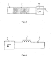
- Figure 2 is a top-down view diagram depicting the first antenna coil that is the main component of the transmission antenna of the present invention.
- Figure 3 is a circuit diagram of the first embodiment of the transmission antenna of the present invention.
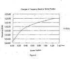
- Figure 4 is a diagram depicting the relationship between screw position and resonance circuit frequency in the transmission antenna of the present invention.
- Figure 5 is a top-down view diagram depicting a modified example of the first antenna coil that is the main component of the transmission antenna of the present invention.
- Figure 6 is a perspective diagram depicting the second antenna coil that is the main component of the second embodiment of the transmission antenna of the present invention.
- Figure 7 is a circuit diagram of the second embodiment of the transmission antenna of the present invention.
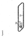
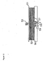
- Figure 8 is a perspective diagram depicting the structure of a resonance circuit wherein the second embodiment of the transmission antenna of the present invention is realized using the antenna coil depicted in Figure 6.
- Figure 9 is a perspective view depicting a case to house the resonance circuit of Figure 8.
- Figure 10 is a top-down view diagram depicting the lid of the case of Figure 9.
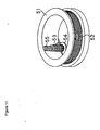
- Figure 11 is a perspective diagram depicting the structure of a resonance circuit when the second embodiment of the transmission antenna of the present invention is realized using a bobbin as an antenna coil.
- Figure 12 is a full-frontal diagram depicting the structure of a resonance circuit when the second embodiment of the transmission antenna of the present invention is realized using a bobbin as an antenna coil.
- the transmission antenna of the present embodiment is outfitted with a ferrite core (1) and a capacitor (2).
- An antenna coil (3) is mounted by being wound onto the ferrite core (1).
- the core (1) forms a flat bar and mated to one of its lengthwise ends is a small flat piece of plastic (a non-magnetic material) that serves as a distance adjuster (4).
- a distance adjuster (4) formed in one end of the distance adjuster (4) is an indented part (41) whose size corresponds to an end of core (1).
- One end of core (1) is inserted into, and thus mated to, this indented part.
- a screw hole (42) facing the core (1) end mated to the aforementioned indented part (41) is formed in the end face of that side of the distance adjuster (4) wherein the indented part (41) is not formed.
- a screw (5) with a small core made of, for example, ferrite is threaded into this screw hole (42).
- the capacitor (2) is connected to the antenna coil (3) of antenna coil (L) outfitted with a core (1) on which the antenna coil (3) is mounted by winding.
- the inductance of antenna coil (L) and capacitor (2) form a serial resonance circuit.
- the inductance value of the antenna coil (L) can be changed by adjusting the thread volume of the screw (5).
- Figure 4 depicts the relationship between the screw (5) position (distance from the core [1]) and the frequency of the resonance circuit.
- the resonance frequency is lowest when the screw (5) is in direct contact with the core (1).
- the resonance frequency can be gradually increased by diminishing the screw thread volume.
- the capacity of the capacitor (2) used is 3300pF.
- the size of the core (1) is 50(mm) x 12(mm) x 3(mm).
- the screw (5) size is: Diameter 3.8(mm) and length 3.5(mm); the antenna coil (3) used is wound 102 times.
- the transmission antenna is such that the antenna coil (L) and the capacitor (2) are connected and are further connected to an external derivation lead wire (6). This is housed in a case (7) with a lid not shown in the figures. As Figure 3 depicts, this is connected to a transmission circuit (8) and electromagnetic waves can be transmitted.
- the perforation direction of the screw hole (42) serving as the distance adjuster is the direction of the magnetic flux generated by the core (1). Since the small core screw is mobile in the direction of the magnetic flux generated by the core (1) whereon the antenna coil (3) is mounted by winding, the direction of the magnetic flux is stable. Such generation can occur without changing the antenna directionality, even when changing the resonance frequency by adjusting the thread volume of the screw (5).
- the material of the aforementioned screw (5) is ferrite.
- the resonance frequency of the resonance circuit there is a relation between the thread volume of the screw (2) [sic.] as depicted in Figure 4 and the resonance frequency of the resonance circuit.
- the screw (2) [sic.] is made of copper or aluminum with a relative magnetic permeability below 1 (a negative relative magnetic permeability)
- the resonance frequency can be increased as the thread volume of the screw (2) [sic.] is increased.
- a structure is depicted whereby a screw (5) is thread into the screw hole (42) that serves as a distance adjuster. Also appropriate, though, is a structure whereby a hole without a screw is provided instead of a screw hole (42) and wherein is inserted a slideable tubular pin to an appropriate position and fixed by an adhesive, etc.
- FIG 5 depicts a structural example of an antenna coil not provided with a distance adjuster (4).
- This antenna coil is such that a screw hole (43), which is a small hole, is formed from an end of the core (1).
- a screw hole (43) Threaded into this screw hole (43) is a screw (5) made of ferrite.
- the screw (5) is slideable and can reach an inductance value corresponding to the thread volume.
- the relation between the thread volume and the resonance circuit frequency is the same in an antenna coil structure in this way and that depicted in Figure 4.
- depicted is a structure whereby the screw hole (43) is formed in the center of the end of the core (1).
- this location is not limited to the center and may be any position, provided it is in the end of the core (1).
- the transmission antenna has the circuit structure that depicted in Figure 3.
- Figure 7 depicts, a first coil whereby the inductance value is set and a second coil whereby the inductance value is variable can be used.
- the first coil (L1 ), the second coil (L2), and the capacitor (2) are connected serially to form a serial resonance circuit. This is connected to a transmission circuit such that electromagnetic waves can be emitted.
- the second coil (L2) that Figure 7 depicts corresponds to the small L-value adjustment coil comprised of the second coil (32) Figure 6 [sic.] depicts and to the coil (53), bobbin (54), and screw (55) that Figure 11 and Figure 12 depict.
- the first coil (L1) in Figure 7 corresponds to the first coil (31) Figure 8 depicts and the coil (52) Figure 11 depicts.
- the structure is such that the small L-value adjustment coil (L2) is connected to the antenna coil (L1) which becomes the main (coil).
- Figure 8 depicts a structural example of a serial resonance circuit using the coil depicted in Figure 6.
- Serially connected are a first coil (31) coiled about a hollow core in a generally square-shaped loop, a second coil (32) depicted in Figure 6, and a capacitor (2).
- Such a serial resonance circuit is housed in a case (33) depicted in Figure 9 and covered with a lid (34) depicted in Figure 10.
- the case (33) is formed in the shape of a generally square loop and is provided with a groove (35) to house the aforementioned first coil (31) and, on one side of groove (35), with a rectangular parallelepiped chamber (36). Drawn out from the chamber (36) to the outside are, respectively, a lead wire extending from one end of capacitor (2) and a lead wire extending from the first coil and connected to the transmission circuit (8).
- the second coil (32) is the antenna coil that Figure 6 depicts and the thread volume of the screw (12) is appropriately adjusted to the desired property.
- FIG 11 and Figure 12 depict structural examples of a serial resonance circuit relating to a different structure used in a transmission antenna.
- Coil (52) is coiled onto the first bobbin (51).
- the second bobbin (54) on which coil (53) is mounted by winding is provided integrally to the first bobbin (51).
- a screw (55) In the center of the second bobbin (54) is provided a screw (55), which is a mobile ferrite core.
- the coil structure comprising this second bobbin (54) and the screw (55) is basically equivalent to the antenna coil structure that Figure 6 depicts.
- terminals (57), (58), and (59) are terminals (57), (58), and (59). Between terminal (57) and (58) are connected a capacitor (2) while one end of the coil (52) is connected to terminal (59).
- a serial resonance circuit is formed by connections whereby the coil of the first bobbin (51) and coil (52) correspond to coil (L1) in Figure 7, while the coil of the second bobbin (54) and coil (53) correspond to coil (L2) in Figure 7.
- Terminal (57) and terminal (59) are connected to transmission circuit (8) to form a transmission antenna. In this transmission antenna too, the resonance frequency of the serial resonance circuit is set to the desired value by appropriately adjusting the thread volume of the screw (55).
- a small core smaller in size than the former and the distance between the aforementioned core and the aforementioned small core is adjusted.
- a screw made of ferrite, etc. whose inductance value is adjustable is provided and the screw volume of this screw is adjusted.
- the resonance frequency of the serial resonance circuit is set as desired by this adjustment, the inductance of the resonance frequency in the transmission antenna decreases, the current value in the resonance circuit increases, the magnetic flux radiated from the transmission antenna increases and, with the same power consumption, the communication distance can be extended, which is extremely beneficial.
Landscapes
- Engineering & Computer Science (AREA)
- Computer Security & Cryptography (AREA)
- Radar, Positioning & Navigation (AREA)
- Remote Sensing (AREA)
- Support Of Aerials (AREA)
- Coils Or Transformers For Communication (AREA)
- Details Of Aerials (AREA)
- Near-Field Transmission Systems (AREA)
- Burglar Alarm Systems (AREA)
Priority Applications (1)
| Application Number | Priority Date | Filing Date | Title |
|---|---|---|---|
| EP07013114A EP1887651B1 (fr) | 2001-10-22 | 2002-09-30 | Bobine d'antenne et antenne de transmission |
Applications Claiming Priority (3)
| Application Number | Priority Date | Filing Date | Title |
|---|---|---|---|
| WOPCT/EP01/09251 | 2001-10-22 | ||
| PCT/JP2001/009251 WO2003036760A1 (fr) | 2001-10-22 | 2001-10-22 | Bobine d'antenne et antenne de transmission |
| PCT/JP2002/010191 WO2003036761A1 (fr) | 2001-10-22 | 2002-09-30 | Bobine d'antenne et antenne de transmission |
Related Child Applications (1)
| Application Number | Title | Priority Date | Filing Date |
|---|---|---|---|
| EP07013114A Division EP1887651B1 (fr) | 2001-10-22 | 2002-09-30 | Bobine d'antenne et antenne de transmission |
Publications (2)
| Publication Number | Publication Date |
|---|---|
| EP1450436A1 true EP1450436A1 (fr) | 2004-08-25 |
| EP1450436A4 EP1450436A4 (fr) | 2004-12-29 |
Family
ID=34509561
Family Applications (2)
| Application Number | Title | Priority Date | Filing Date |
|---|---|---|---|
| EP07013114A Expired - Lifetime EP1887651B1 (fr) | 2001-10-22 | 2002-09-30 | Bobine d'antenne et antenne de transmission |
| EP02777801A Ceased EP1450436A4 (fr) | 2001-10-22 | 2002-09-30 | Bobine d'antenne et antenne de transmission |
Family Applications Before (1)
| Application Number | Title | Priority Date | Filing Date |
|---|---|---|---|
| EP07013114A Expired - Lifetime EP1887651B1 (fr) | 2001-10-22 | 2002-09-30 | Bobine d'antenne et antenne de transmission |
Country Status (7)
| Country | Link |
|---|---|
| US (1) | US7081864B2 (fr) |
| EP (2) | EP1887651B1 (fr) |
| JP (1) | JP3735104B2 (fr) |
| CN (1) | CN100452532C (fr) |
| AT (1) | ATE487247T1 (fr) |
| DE (1) | DE60238224D1 (fr) |
| WO (2) | WO2003036760A1 (fr) |
Cited By (5)
| Publication number | Priority date | Publication date | Assignee | Title |
|---|---|---|---|---|
| EP1630899A4 (fr) * | 2004-03-04 | 2008-05-21 | Matsushita Electric Industrial Co Ltd | Dispositif d'antenne et systeme de communications utilisant celui-ci |
| NL1034493C2 (nl) * | 2007-10-09 | 2009-04-14 | Nedap Nv | Magneet ferriet antenne. |
| EP1906489B1 (fr) * | 2006-09-28 | 2010-03-31 | Sumida Corporation | Dispositif d'antenne pour montage sur une carte de circuits imprimés |
| JP5945082B1 (ja) * | 2016-01-22 | 2016-07-05 | 日本電信電話株式会社 | アンテナ |
| EP3916910A1 (fr) | 2020-05-26 | 2021-12-01 | Premo, S.A. | Antenne basse fréquence longue portée |
Families Citing this family (28)
| Publication number | Priority date | Publication date | Assignee | Title |
|---|---|---|---|---|
| KR100979153B1 (ko) * | 2002-11-22 | 2010-08-31 | 인터디지탈 테크날러지 코포레이션 | 복소 가중치 생성(cwg) 알고리즘을 이용한 레이크 수신기에서의 채널 이득 추정 |
| RU2321926C2 (ru) * | 2003-10-16 | 2008-04-10 | Сумида Корпорейшн | Антенная катушка и антенное устройство |
| JP4707999B2 (ja) * | 2004-11-12 | 2011-06-22 | スミダコーポレーション株式会社 | アンテナ用インダクタンス素子 |
| JP2006180031A (ja) * | 2004-12-21 | 2006-07-06 | Hitachi Metals Ltd | 送信アンテナおよびこれを備えた送信装置 |
| JP4667397B2 (ja) * | 2005-01-17 | 2011-04-13 | 富士通株式会社 | 通信装置および通信方法 |
| JP2006229758A (ja) * | 2005-02-18 | 2006-08-31 | Matsushita Electric Works Ltd | アンテナ装置 |
| EP1854637B1 (fr) * | 2005-03-03 | 2011-03-02 | Toshiba TEC Kabushiki Kaisha | Imprimante et dispositif de communication a puce a circuit integre |
| US7825543B2 (en) | 2005-07-12 | 2010-11-02 | Massachusetts Institute Of Technology | Wireless energy transfer |
| KR101118710B1 (ko) | 2005-07-12 | 2012-03-13 | 메사추세츠 인스티튜트 오브 테크놀로지 | 무선 비-방사성 에너지 전달 |
| KR101060115B1 (ko) | 2006-07-21 | 2011-08-29 | 스미다 코포레이션 가부시키가이샤 | 코일 부품 |
| DE102006036288B4 (de) * | 2006-08-03 | 2009-02-12 | Siemens Ag | Synchronmotor, geberloses Motorsystem, sowie ein Verfahren zum Betreiben eines geberlosen Motorsystems mit einem Synchronmotor |
| CN101501929B (zh) * | 2006-08-09 | 2012-12-05 | 株式会社村田制作所 | 天线线圈及天线装置 |
| JP4881170B2 (ja) * | 2007-01-23 | 2012-02-22 | スミダコーポレーション株式会社 | アンテナ用コイル部品 |
| US7733283B2 (en) * | 2007-10-16 | 2010-06-08 | Sumida Corporation | Antenna Device |
| EP2345100B1 (fr) | 2008-10-01 | 2018-12-05 | Massachusetts Institute of Technology | Transfert d'énergie sans fil en champ proche efficace utilisant des variations de système adiabatique |
| JP5350192B2 (ja) * | 2009-11-20 | 2013-11-27 | オムロンオートモーティブエレクトロニクス株式会社 | 送信用アンテナ |
| US8669909B2 (en) * | 2011-11-30 | 2014-03-11 | Panasonic Corporation | Antenna, antenna apparatus, and communication apparatus |
| JP6171726B2 (ja) * | 2013-08-23 | 2017-08-02 | 株式会社Ihi | 非接触給電装置の製造方法 |
| WO2015020141A1 (fr) * | 2013-08-08 | 2015-02-12 | 株式会社Ihi | Procédé pour fabriquer un dispositif d'alimentation électrique sans contact et résonateur |
| JP6225551B2 (ja) * | 2013-08-08 | 2017-11-08 | 株式会社Ihi | 共振器 |
| DE102014106815B4 (de) * | 2014-05-14 | 2024-01-18 | Infineon Technologies Ag | Kommunikationsmodul |
| JP2017103549A (ja) | 2015-11-30 | 2017-06-08 | スミダコーポレーション株式会社 | アンテナ装置およびアンテナ装置の製造方法 |
| CN110892582B (zh) * | 2017-07-25 | 2022-04-19 | 株式会社村田制作所 | 天线线圈及其制造方法 |
| JP6547877B2 (ja) * | 2018-06-14 | 2019-07-24 | スミダコーポレーション株式会社 | アンテナ装置 |
| WO2021014701A1 (fr) * | 2019-07-19 | 2021-01-28 | 株式会社ワコム | Stylo électronique et appareil de saisie d'écriture manuelle |
| CN115617518B (zh) * | 2022-10-13 | 2025-09-19 | 维沃移动通信有限公司 | 线程管理方法、装置、电子设备及存储介质 |
| CN116315565B (zh) * | 2022-12-20 | 2025-08-15 | 华翊博奥(北京)量子科技有限公司 | 一种螺旋谐振器 |
| EP4443647A1 (fr) * | 2023-04-05 | 2024-10-09 | Schaffner EMV AG | Support d'enroulement, antenne et procédé de fabrication d'une antenne |
Family Cites Families (29)
| Publication number | Priority date | Publication date | Assignee | Title |
|---|---|---|---|---|
| US401899A (en) | 1889-04-23 | Leonard paget | ||
| DE449450C (de) * | 1925-06-06 | 1927-09-14 | Friedrich Dessauer Dr | Verfahren zur Analyse von Stoffen durch Erregung charakteristischer Sekundaerstrahlen |
| GB449450A (en) * | 1934-12-28 | 1936-06-26 | Eduard Michaelis | Improvements in and relating to adjustable high frequency coils |
| GB707142A (en) * | 1950-12-04 | 1954-04-14 | Wladimir John Polydoroff | Improvements in and relating to antennas for radio apparatus |
| US2624004A (en) * | 1952-05-16 | 1952-12-30 | Wladimir J Polydoroff | Ferromagnetic antenna |
| DE1053048B (de) * | 1957-08-28 | 1959-03-19 | Telefunken Gmbh | Einrichtung zum Abgleichen eines Schwingungskreises |
| JPS5938773B2 (ja) * | 1974-01-10 | 1984-09-19 | 株式会社東芝 | レベルシフト回路 |
| JPS50102234U (fr) * | 1974-01-25 | 1975-08-23 | ||
| US4101899A (en) * | 1976-12-08 | 1978-07-18 | The United States Of America As Represented By The Secretary Of The Army | Compact low-profile electrically small vhf antenna |
| FR2339258A1 (fr) | 1977-02-22 | 1977-08-19 | Optalix | Procede et dispositif de reglage d'un collecteur d'ondes bobines-barreau ferrite |
| US4280129A (en) * | 1978-09-09 | 1981-07-21 | Wells Donald H | Variable mutual transductance tuned antenna |
| JPS58172208A (ja) | 1982-04-01 | 1983-10-11 | Mitsubishi Chem Ind Ltd | 結晶性バナジウム−リン系複合酸化物 |
| JPS58172208U (ja) * | 1982-05-13 | 1983-11-17 | パイオニア株式会社 | Vhf帯バ−アンテナ |
| IT8222497V0 (it) | 1982-07-22 | 1982-07-22 | Nordica Spa | Struttura di dispositivo di bloccaggio del piede particolarmente per scarponi da sci. |
| JPS5922503U (ja) * | 1982-08-02 | 1984-02-10 | 松下電器産業株式会社 | フエライトアンテナコイル |
| JPS59152703A (ja) * | 1983-02-18 | 1984-08-31 | Matsushita Electric Ind Co Ltd | フエライトアンテナ |
| JPS59191905A (ja) * | 1984-04-02 | 1984-10-31 | Matsushita Electric Ind Co Ltd | バ−アンテナ |
| JPS61211U (ja) * | 1984-06-07 | 1986-01-06 | 日本電信電話株式会社 | 雑音阻止トランス |
| US5250944A (en) * | 1990-10-29 | 1993-10-05 | Bio Medic Data Systems, Inc. | Antenna and driving circuit for transmitting and receiving images to and from a passive transponder |
| US5521609A (en) * | 1995-01-13 | 1996-05-28 | The United States Of America As Represented By The Administrator Of The National Aeronautics And Space Administration | Magnetic antenna using metallic glass |
| JPH09270742A (ja) * | 1996-03-29 | 1997-10-14 | Matsushita Electric Ind Co Ltd | 非接触icカード通信装置 |
| DE29607866U1 (de) * | 1996-04-19 | 1997-08-14 | Junghans Uhren Gmbh, 78713 Schramberg | Magnetische Antenne für eine Armbanduhr |
| JPH11340734A (ja) * | 1998-05-27 | 1999-12-10 | Aisin Seiki Co Ltd | ループアンテナ装置 |
| KR100291321B1 (ko) * | 1999-03-26 | 2001-05-15 | 소호연 | 동물훈련장치의 송.수신용 안테나 |
| DE19923634A1 (de) * | 1999-05-22 | 2000-12-07 | Mannesmann Vdo Ag | Sende- und Empfangseinrichtung |
| FR2805930B1 (fr) | 2000-02-18 | 2005-12-30 | Aisin Seiki | Dispositif d'antenne en boucle |
| JP3941323B2 (ja) * | 2000-03-10 | 2007-07-04 | アイシン精機株式会社 | ループアンテナ装置 |
| JP2001297918A (ja) * | 2000-04-11 | 2001-10-26 | Mitsubishi Electric Corp | コイルアンテナおよび携帯通信機 |
| WO2002005236A1 (fr) * | 2000-07-06 | 2002-01-17 | C. Crane Company | Antenne a double enroulement |
-
2001
- 2001-10-22 WO PCT/JP2001/009251 patent/WO2003036760A1/fr not_active Ceased
-
2002
- 2002-09-30 DE DE60238224T patent/DE60238224D1/de not_active Expired - Lifetime
- 2002-09-30 US US10/493,406 patent/US7081864B2/en not_active Expired - Lifetime
- 2002-09-30 WO PCT/JP2002/010191 patent/WO2003036761A1/fr not_active Ceased
- 2002-09-30 AT AT07013114T patent/ATE487247T1/de not_active IP Right Cessation
- 2002-09-30 EP EP07013114A patent/EP1887651B1/fr not_active Expired - Lifetime
- 2002-09-30 EP EP02777801A patent/EP1450436A4/fr not_active Ceased
- 2002-09-30 JP JP2003539136A patent/JP3735104B2/ja not_active Expired - Lifetime
- 2002-09-30 CN CNB028209605A patent/CN100452532C/zh not_active Expired - Lifetime
Cited By (7)
| Publication number | Priority date | Publication date | Assignee | Title |
|---|---|---|---|---|
| EP1630899A4 (fr) * | 2004-03-04 | 2008-05-21 | Matsushita Electric Industrial Co Ltd | Dispositif d'antenne et systeme de communications utilisant celui-ci |
| EP1906489B1 (fr) * | 2006-09-28 | 2010-03-31 | Sumida Corporation | Dispositif d'antenne pour montage sur une carte de circuits imprimés |
| NL1034493C2 (nl) * | 2007-10-09 | 2009-04-14 | Nedap Nv | Magneet ferriet antenne. |
| EP2048738A1 (fr) * | 2007-10-09 | 2009-04-15 | N.V. Nederlandsche Apparatenfabriek NEDAP | Antenne ferrite magnétique |
| JP5945082B1 (ja) * | 2016-01-22 | 2016-07-05 | 日本電信電話株式会社 | アンテナ |
| EP3916910A1 (fr) | 2020-05-26 | 2021-12-01 | Premo, S.A. | Antenne basse fréquence longue portée |
| US11949156B2 (en) | 2020-05-26 | 2024-04-02 | Premo, S.L. | Long range low frequency antenna |
Also Published As
| Publication number | Publication date |
|---|---|
| WO2003036760A1 (fr) | 2003-05-01 |
| EP1450436A4 (fr) | 2004-12-29 |
| EP1887651A1 (fr) | 2008-02-13 |
| ATE487247T1 (de) | 2010-11-15 |
| WO2003036761A1 (fr) | 2003-05-01 |
| CN1575531A (zh) | 2005-02-02 |
| JP3735104B2 (ja) | 2006-01-18 |
| DE60238224D1 (de) | 2010-12-16 |
| EP1887651B1 (fr) | 2010-11-03 |
| HK1117942A1 (en) | 2009-01-23 |
| US7081864B2 (en) | 2006-07-25 |
| CN100452532C (zh) | 2009-01-14 |
| JPWO2003036761A1 (ja) | 2005-02-17 |
| US20050030251A1 (en) | 2005-02-10 |
Similar Documents
| Publication | Publication Date | Title |
|---|---|---|
| US7081864B2 (en) | Antenna coil and transmission antenna | |
| US8305217B2 (en) | Field improving system provided with resonator | |
| CN101047058B (zh) | 线圈部件 | |
| US8896490B2 (en) | Three-axis antenna and core assembly used therein | |
| EP2693454B1 (fr) | Bobine de réception de puissance, dispositif de réception de puissance et système de transmission de puissance sans contact | |
| EP2304859A2 (fr) | Antennes en ferrite pour transfert d énergie sans fil | |
| JP2010539857A (ja) | ワイヤレスエネルギー伝送のための送信機および受信機 | |
| KR20050098880A (ko) | 미소 루프 안테나를 이용한 안테나 장치 및 그 안테나 장치를 사용한 무선 통신 장치 | |
| JP2009259273A (ja) | 共振器付フィールド改善システム | |
| KR101503221B1 (ko) | 웨어러블 디바이스의 공진형 무선충전을 위한 2중 스파이럴 안테나 모듈 | |
| RU98104593A (ru) | Антенна с питанием от расположенных рядом катушек для портативного устройства радиосвязи | |
| US10629369B2 (en) | Wireless power transmission device for transmitting power using magnetic field and electric field, and wireless power receiving device for receiving power from the wireless power transmission device | |
| CN109524195B (zh) | 共模扼流圈以及无线充电用电路 | |
| JPWO2020003568A1 (ja) | Rfidタグ及びrfid付き物品 | |
| HK1117942B (en) | Antenna coil and transmission antenna | |
| JPH03270403A (ja) | アンテナ回路及び小型携帯無線機 | |
| JP2002353725A (ja) | 電磁誘導アンテナ装置 | |
| CN116264355A (zh) | 一种三轴低剖面的低频磁场发射天线 | |
| JP2006165774A (ja) | トランスポンダ機能を付属した立体変形を含む形状変形フレキシブルなアンテナループコイル。 | |
| US20050141742A1 (en) | Induction coil for a hearing aid | |
| JP2008022056A (ja) | 送信用アンテナ及びキーレスエントリシステム | |
| CN215120164U (zh) | 无线充电线圈 | |
| JPH05166623A (ja) | 小形固定コイル | |
| JPH07303006A (ja) | フェライトバーアンテナとその同調周波数調整方法 | |
| JPS6235702A (ja) | 空中線装置 |
Legal Events
| Date | Code | Title | Description |
|---|---|---|---|
| PUAI | Public reference made under article 153(3) epc to a published international application that has entered the european phase |
Free format text: ORIGINAL CODE: 0009012 |
|
| 17P | Request for examination filed |
Effective date: 20040514 |
|
| AK | Designated contracting states |
Kind code of ref document: A1 Designated state(s): AT BE BG CH CY CZ DE DK EE ES FI FR GB GR IE IT LI LU MC NL PT SE SK TR |
|
| A4 | Supplementary search report drawn up and despatched |
Effective date: 20041112 |
|
| RIC1 | Information provided on ipc code assigned before grant |
Ipc: 7H 01Q 7/08 B Ipc: 7H 01Q 1/32 A |
|
| RAP1 | Party data changed (applicant data changed or rights of an application transferred) |
Owner name: SUMIDA CORPORATION |
|
| 17Q | First examination report despatched |
Effective date: 20050210 |
|
| APBN | Date of receipt of notice of appeal recorded |
Free format text: ORIGINAL CODE: EPIDOSNNOA2E |
|
| APAF | Appeal reference modified |
Free format text: ORIGINAL CODE: EPIDOSCREFNE |
|
| APBT | Appeal procedure closed |
Free format text: ORIGINAL CODE: EPIDOSNNOA9E |
|
| STAA | Information on the status of an ep patent application or granted ep patent |
Free format text: STATUS: THE APPLICATION HAS BEEN REFUSED |
|
| 18R | Application refused |
Effective date: 20071016 |