EP1450216A1 - Korotronanordung mit einer Spannungsversorgungseinheit - Google Patents
Korotronanordung mit einer Spannungsversorgungseinheit Download PDFInfo
- Publication number
- EP1450216A1 EP1450216A1 EP04011669A EP04011669A EP1450216A1 EP 1450216 A1 EP1450216 A1 EP 1450216A1 EP 04011669 A EP04011669 A EP 04011669A EP 04011669 A EP04011669 A EP 04011669A EP 1450216 A1 EP1450216 A1 EP 1450216A1
- Authority
- EP
- European Patent Office
- Prior art keywords
- corotron
- corotron wire
- arrangement according
- supply unit
- wire insert
- Prior art date
- Legal status (The legal status is an assumption and is not a legal conclusion. Google has not performed a legal analysis and makes no representation as to the accuracy of the status listed.)
- Granted
Links
Images






Classifications
-
- G—PHYSICS
- G03—PHOTOGRAPHY; CINEMATOGRAPHY; ANALOGOUS TECHNIQUES USING WAVES OTHER THAN OPTICAL WAVES; ELECTROGRAPHY; HOLOGRAPHY
- G03B—APPARATUS OR ARRANGEMENTS FOR TAKING PHOTOGRAPHS OR FOR PROJECTING OR VIEWING THEM; APPARATUS OR ARRANGEMENTS EMPLOYING ANALOGOUS TECHNIQUES USING WAVES OTHER THAN OPTICAL WAVES; ACCESSORIES THEREFOR
- G03B15/00—Special procedures for taking photographs; Apparatus therefor
- G03B15/02—Illuminating scene
-
- G—PHYSICS
- G03—PHOTOGRAPHY; CINEMATOGRAPHY; ANALOGOUS TECHNIQUES USING WAVES OTHER THAN OPTICAL WAVES; ELECTROGRAPHY; HOLOGRAPHY
- G03G—ELECTROGRAPHY; ELECTROPHOTOGRAPHY; MAGNETOGRAPHY
- G03G15/00—Apparatus for electrographic processes using a charge pattern
- G03G15/02—Apparatus for electrographic processes using a charge pattern for laying down a uniform charge, e.g. for sensitising; Corona discharge devices
- G03G15/0208—Apparatus for electrographic processes using a charge pattern for laying down a uniform charge, e.g. for sensitising; Corona discharge devices by contact, friction or induction, e.g. liquid charging apparatus
-
- G—PHYSICS
- G03—PHOTOGRAPHY; CINEMATOGRAPHY; ANALOGOUS TECHNIQUES USING WAVES OTHER THAN OPTICAL WAVES; ELECTROGRAPHY; HOLOGRAPHY
- G03G—ELECTROGRAPHY; ELECTROPHOTOGRAPHY; MAGNETOGRAPHY
- G03G15/00—Apparatus for electrographic processes using a charge pattern
- G03G15/02—Apparatus for electrographic processes using a charge pattern for laying down a uniform charge, e.g. for sensitising; Corona discharge devices
- G03G15/0258—Apparatus for electrographic processes using a charge pattern for laying down a uniform charge, e.g. for sensitising; Corona discharge devices provided with means for the maintenance of the charging apparatus, e.g. cleaning devices, ozone removing devices G03G15/0225, G03G15/0291 takes precedence
-
- G—PHYSICS
- G03—PHOTOGRAPHY; CINEMATOGRAPHY; ANALOGOUS TECHNIQUES USING WAVES OTHER THAN OPTICAL WAVES; ELECTROGRAPHY; HOLOGRAPHY
- G03G—ELECTROGRAPHY; ELECTROPHOTOGRAPHY; MAGNETOGRAPHY
- G03G15/00—Apparatus for electrographic processes using a charge pattern
- G03G15/02—Apparatus for electrographic processes using a charge pattern for laying down a uniform charge, e.g. for sensitising; Corona discharge devices
- G03G15/0291—Apparatus for electrographic processes using a charge pattern for laying down a uniform charge, e.g. for sensitising; Corona discharge devices corona discharge devices, e.g. wires, pointed electrodes, means for cleaning the corona discharge device
-
- H—ELECTRICITY
- H01—ELECTRIC ELEMENTS
- H01T—SPARK GAPS; OVERVOLTAGE ARRESTERS USING SPARK GAPS; SPARKING PLUGS; CORONA DEVICES; GENERATING IONS TO BE INTRODUCED INTO NON-ENCLOSED GASES
- H01T19/00—Devices providing for corona discharge
-
- G—PHYSICS
- G03—PHOTOGRAPHY; CINEMATOGRAPHY; ANALOGOUS TECHNIQUES USING WAVES OTHER THAN OPTICAL WAVES; ELECTROGRAPHY; HOLOGRAPHY
- G03G—ELECTROGRAPHY; ELECTROPHOTOGRAPHY; MAGNETOGRAPHY
- G03G2215/00—Apparatus for electrophotographic processes
- G03G2215/02—Arrangements for laying down a uniform charge
- G03G2215/026—Arrangements for laying down a uniform charge by coronas
- G03G2215/027—Arrangements for laying down a uniform charge by coronas using wires
Definitions
- the invention relates to an arrangement for a corotron for electrographic processes, especially in a printer or Copier.
- the voltage supply unit takes the support of the arrangement to supply the corotron.
- the corotron is used for the electrical charging of a carrier material for a latent image, especially a photoconductor tape.
- a corotron wire unit for a contains electrographic printing or copying equipment.
- the Corotron wire is provided with end pieces, the corotron wire is arranged in an insert, which is a reflector element and contains an electrical connection terminal.
- This arrangement enables the corotron wire to be used easy to replace together with the slot.
- the corotron wire together with the insert opposite the carrier material after the exchange is realigned to the parallel Alignment of the longitudinal axis of the corotron wire to the Adjust the level of the substrate exactly. For this activity qualified service personnel is required.
- the corotron wire remains in the corotron arrangement and the insertion process is finished. Removing the corotron wire the corotron arrangement is not possible with this holding element. The removal of the corotron wire is only by mechanical Action on the corotron wire and / or on it Fastening elements possible. With this procedure the Break the corotron wire. Especially with glass-coated corotron wires this poses a significant risk of injury for the executing person.
- US-A 3 685 895 describes a rack for electrostatic Charging a carrier material using corotron wires are stored in blocks.
- the blocks are over one the carrier material movable arm arranged.
- the arm is over along the right and left edges of the rack guided the carrier material along.
- On the movable arm is a voltage supply unit for supplying the corotron wires intended.
- a frame for holding a corotron wire is known to be vertical can be used in an image forming apparatus. Feeding the supply voltage of the corotron wire from a power supply unit to the frame is done with the help of connectors.
- the object of the invention is a simple structure to indicate for a corotron by which a high print quality is achieved.
- This arrangement ensures that the individual elements are arranged compactly, and that the paths of the high-voltage lines are minimized.
- the interference caused by a stray electrical field on the carrier material are accordingly low.
- the carrier arranged at least one corotron wire insert, in which at least a corotron wire is arranged, in particular up to three corotron wires are arranged.
- the printer or copier is achieved to be a maintenance-friendly Arrangement is given which enables the corotron wire drawer from the printer or copier remove to e.g. an exchange of the corotron wires outside the printer or copier. It exists but also the possibility of entire corotron wire inserts during service work to replace the downtimes reduce.
- the variable arrangement of up to three corotron wires for each corotron wire insert is one Corotron wire inserts to various printers or copiers given. If required, several corotron wire inserts can also be used arranged in the direction of movement of the carrier material to intensify the loading or unloading of the carrier material.
- the voltage supply unit in a parallel plane of the corotron wire insert arranged. This ensures that the Power supply unit in the immediate vicinity of the corotron wire insert is arranged and thus interference are low due to the voltage supply unit.
- the effect of the stray electrical field of the voltage supply unit on the carrier material is between elements the voltage supply unit and the carrier material, in particular reduced by an electrically conductive reflector.
- the corotron wire insert contains at least one reflector element, in particular as part of a hard chrome-plated extruded aluminum profile is formed by electrically insulating elements is isolated from the potential of the housing. This ensures that the ionization cloud from the reflector towards Carrier material reflects and thereby the charging of the photoconductor tape intensified.
- a hard chrome plated Extruded aluminum is an effective protection against corrosion given the reflector element.
- the insulated reflector element to a predetermined To set potential to reflectivity of the reflector to increase.
- the slots formed as an extruded profile, due to the ozone-air mixture created in the corotron device is suctioned off.
- the extraction of the ozone-air mixture can be done via a channel that the reflector element with its side facing away from the corotron wire and the Form carrier.
- the channel is connected with a connector Ozone depletion unit connected.
- connecting elements are on their contact surfaces so that they, in particular by mutual overlap, sufficient tightness guarantee or it will be on the contact surfaces the connecting elements arranged additional sealing elements. This ensures that the emerging and for humans harmful ozone is safely discharged and a hazard is excluded for humans.
- the longer one is two parallel sides of the trapezoidal cross section of the first Connecting element recessed so that the second connecting element in the first connecting element on the overlap length can be used.
- the trapezoidal Cross sections that preferably have a constant wall thickness and have the shape of an isosceles trapezium, so they are on top of each other matched that the inner surfaces of the first connecting element and the outer surfaces of the second connector Form sealing surfaces. Touch these sealing surfaces itself in the operating position and thus seal the connecting elements against each other.
- the axes of symmetry of the two trapezoidal Cross sections lie on a straight line.
- the slanted legs center the two Connecting elements when the two approach each other Fasteners on their axes of symmetry.
- each corotron wire insert through a separate power supply unit fed, which contains at least two power supplies, where a power supply a voltage, preferably in the range of 16 to 20 kV with a frequency in the range from 3 to 5 kHz, to supply the corotron wire and a second power supply a DC voltage, preferably in the range from 3 to 5 kV, generated to supply the reflector.
- the production and the service is due to identical corotron wire inserts in the printer or copier as well as in various Printers and copiers greatly simplified and that Warehousing is reduced.
- each corotron wire insert attached at least one distribution element.
- This distribution element serves on the one hand as a mechanical actuating element for handling the corotron wire insert and on the other hand as an insulated electrical connector for Connect the power supply unit to the corotron wire.
- the connector is on the power supply unit and / or movably arranged on the distribution element.
- a preferred option is the connector spring-loaded. This ensures that the corotron wire insert is not firmly connected to the carrier. The self-adjustment of the corotron wire insert is through the Connector not hindered.
- the carrier is made of an insulating plastic and has an H-shaped cross section.
- the power supply unit in the first rectangular recess of the H-shaped profile is the power supply unit and in the second rectangular recess the corotron wire insert arranged.
- the second is rectangular Cutout facing the carrier material.
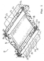
- Figure 1 is a swivel bracket 10 with two corotron arrangements 12a, 12b, being in the corotron arrangement 12a, a corotron wire insert 14a is installed. As well can have a similar corotron wire insert in the corotron arrangement 12b 14b (not shown) can be arranged. Corotron assemblies 12a and 12b including the corotron wire inserts 14a, 14b are constructed identically. Elements, that for a corotron wire insert 14a, 14b or one Corotron arrangement 12a, 12b described and / or in the figures shown apply to both arrangements.
- corotron arrangement 12b On the corotron arrangement 12b there is a slot 16b for a corotron wire insert 14b is provided.
- the corotron arrangements 12a, 12b are via swivel support boards 18a, 18b interconnected, which are also intended to be others Elements such as Character generators, cleaning units or to record further corotron arrangements.
- the carrier material in this exemplary embodiment a photoconductor band 20, for a latent image, from this perspective, under the Swivel bracket 10 passed in the direction of arrow P1.
- the Swivel bracket 10 can be in any position in the printer or Copier be arranged.
- corotron arrangements 12a, 12b are above the corotron wire inserts 14a, 14b the voltage supply units 22a, 22b arranged, each a first power supply 24a, 24b to generate the corotron wire tension and a second one Power supply unit 26a, 26b for generating one to be applied to the reflector Reflector voltage included.
- At one end everyone Corotron arrangement 12a, 12b are connecting elements 28a, 28b arranged by which in the corotron arrangements 12a, 12b emerging ozone through channels of an ozone depletion unit is fed.
- the connecting elements 28a, 28b are fixed connected to the corotron arrangements 12a, 12b.
- Two more Connecting elements 30a, 30b are with the frame of the printer or copier firmly connected.
- the fasteners 28a, 28b, 30a, 30b have bevels on their contact surfaces at an angle of 45 °, making it easy to adjust the channel transition of the connecting elements 28a, 28b, 30a, 30b to the position of the swivel bracket 10 or to the position the corotron arrangements 12a, 12b is possible.
- each corotron wire unit 14a, 14b is fixed to the corotron wire insert 14a, 14b is.
- the retaining clips 32a, 32b Pulling out the respective corotron wire unit 14a, 14b difficult, which ensures adequate attachment of each Corotron wire unit 14a, 14b in the corotron arrangement in question 12a, 12b guaranteed.
- FIG. 2 shows a section of that shown in FIG. 1 Swivel carrier 10 with the corotron arrangement 12b without a corotron wire insert 14b.
- the corotron arrangement is as described in FIG 12b connected to the swivel support board 18b.
- In the slot 16b for the corotron wire insert 14b are two opposite guide rails 36a and 36b. In this figure there is only one guide rail 36a visible.
- In the corotron arrangement 12b are also a plurality of leaf springs 38 are arranged which have a force in Direction of the photoconductor tape 20 on the corotron wire insert Exercise 14b when installed.
- a vertically movable bushing 40b is also provided which supplies the voltage for the corotron wires.
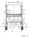
- FIG. 3 shows a section through the corotron arrangement 12a, a carrier 42, the power supply unit 22a and the Photoconductor tape 20 shown.
- the carrier 42 has an H-shaped Cross section in the upper rectangular recess the power supply unit 22a with the first power supply 24a and the second power supply 26a is arranged.
- the power supply unit 22a is on the support by means of screws 44 42 attached.
- the corotron wire insert 14a is of the two opposite guide rails 36a, 36b, those in the lower rectangular recess of the H-shaped Carrier cross section 42 are arranged, received in the carrier 42.
- the guide rails 36a, 36b are fixed to the carrier 42 connected.
- the leaf spring 38 exercises with its spring sections a force on the top of the corotron wire insert 14a in the direction of the photoconductor belt 20.
- the corotron wire insert 14a has reflectors 46, each reflector 46 encloses the respective corotron wire 48 on three sides and the open fourth side of the reflectors 46 the Photoconductor tape 20 is facing.
- the reflectors 46 serve to shield the electrical field.
- the corotron wire insert 14a has an aluminum extruded profile as a load-bearing component 47, which has a U-shape on each side, the legs 49 embrace the guide rails 36a, 36b with play s.
- Reflectors 46 On the opposite side of the photoconductor band 20 Reflectors 46 have slots 50 for sucking out the ozone.
- the ozone is in the through the corotron wire insert 14a and channel 52 formed by the carrier 42 and supplied to an ozone depletion unit.
- the photoconductor belt 20 is supported by the belt support elements 54 performed on the side facing away from the corotron wires 48 of the photoconductor belt 20 are arranged.
- the reflectors 46 have a corrosion-resistant surface, which is preferred is hard chrome plated.
- the entire aluminum extruded profile is preferred 47 hard chrome plated.
- FIG 4 is the corotron wire insert 14a with break lines shown as a partial section.
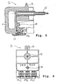
- Distribution element 56 has a handle 57 and is over the aluminum extrusion 47 connected to a support element 58.
- the distribution element 56 and the support element 58 lie on sections of the tape support elements 54 on both sides survive the width of the photoconductor belt 20.
- This Band support elements 54 form the supports for the distribution element 56 and the support element 58.
- the longitudinal axis of the corotron wire 48 is therefore always in a parallel plane to Photoconductor tape 20 aligned.
- the contact pins 60a, 60b, 60c electrically conductively connected to a contact pin 62, which is an electrically conductive connection to the voltage supply unit 24a produces.
- the connection is made preferably by strands or by a plate in the distribution element 56.
- the socket, not shown in this figure 4 40a for receiving the contact pin 62 is on the voltage supply unit 22a movably arranged so that a relative Movement between the corotron wire insert 14a and the Carrier 42 with which the voltage supply unit 22a is fixed connected, is possible.
- Such an arrangement will also referred to as a flying plug.
- the entire corotron wire insert 14a is in one position fixed to the carrier 42 with the aid of the holding clip 32a, movement of the corotron wire insert 14a toward of the photoconductor band 20 is possible.
- the aluminum extruded profile 47 is by means of a wedge 64 and a fastener 68 connected to the distribution element 56.
- the corotron wires 48 are by a locking device 66 in the distribution element 56 and thus in the corotron wire insert 14a fixed.
- the support element 58 of the corotron wire insert 14a is firmly connected to the aluminum extruded profile 47. It consists of an insulating material, e.g. from a insulating plastic. In the support member 58 is in each case one end of the corotron wires 48 is held.
- the aluminum extruded profile 47 is with the support member 58 by fasteners 72 connected.
- FIG. 7 The aluminum extruded profile 47 from FIG. 7 is shown in FIG shown a view rotated by 90 °. Through the slots 50 the ozone is extracted. Openings 70 in the support member 58 are used to accommodate the end bushings of the corotron wires 48th
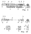
- the corotron wire 48 is in a holding element 74 as well as a view rotated by 90 ° of this arrangement.
- the corotron wire 48 and the holding element 74 are at partially cut this representation.
- At both ends of the One end piece 76, 78 is attached to each corotron wire 48.
- the corotron wire 48 is glass-coated and forms the end pieces 76, 78 one unit.
- the tail 78 has one Socket 82, through which the not shown in Figure 9 Contact pin 60a of the distribution element 56 an electrically conductive Connects to the corotron wire 48.
- Internally of the tail 76 is a spring 80 which is the corotron wire 48 holds under a constant mechanical tension.
- the holding element 74 consists of a Plastic drawing profile with an opening 90 for receiving the Corotron wire 48.
- the opening 90 is of two arched Legs 92 formed which the corotron wire 48 when picking up partially enclose in the holding element 74.
- the arched Legs 92 form resilient elements that form the corotron wire 48 fix in the holding element 74.
- FIG 11 is the corotron wire insert 14a and the corotron wire 48 shown in the holding element 74.
- the corotron wire insert 14a is removed from the printer or copier and is for mounting the corotron wires 48 on a mounting table 94 so that the corotron wires 48 for an operator is visible and easily accessible.
- Arrow P5 is the insertion process of the corotron wire 48 in the Corotron wire insert 14a indicated.
- For insertion in the Corotron wire insert 14a is the corotron wire to be inserted 48 with the end pieces 76, 78 in the holding device 74, the pin 84, the end pieces 76, 78 of the corotron wire 48 fix in the holding element 74.
- the holding element 74 With the holding element 74 is the fixed corotron wire 48 along the Line of arrow P5 inserted into the corotron wire insert 14a, until the corotron wire 48 'with its end pieces 76', 78 'through the locking element 66 in the corotron wire insert 14a is fixed. After fixing the corotron wire 48 'in the corotron wire insert 14a becomes the holding element 74 removed upward from the corotron wire insert 14a. The corotron wire 48 'is ready for use. By the shape of the aluminum extruded profile 47 and the free space given thereby The aluminum extruded profile 47 can be accessed with the reflectors 46 when exchanging the corotron wires 48 easy to clean.
- FIG 12 is the corotron wire insert 14a with the inserted Corotron wire 48 and the holding element 74 from FIG 11 shown.
- the corotron wire 48 is in the holding element 74 parallel to the distribution element 56 with an offset to the aluminum extruded profile 47 in the opening 70 of the support element 58 along the arrow P5 shown in Figure 11.
- the end piece 76 of the corotron wire 48 takes the Position 76 '.
- the holding element 74 is put together with the corotron wire 48 and its end pieces 76, 78 pushed towards distribution element 56, the contact pin 60a (not shown) in the socket 82 of the end piece 78 is introduced.
- the locking element 66 is during insertion of the corotron wire 48 into the corotron wire unit 14a deflected and locked by the end piece 78 in the position 66 ' the corotron wire 48 in the end position 66.
- the locking element 66 is preferably provided by a spring element held in its final position. Then that will Retaining element 74 removed from the corotron wire 48. To expand of the corotron wire 48 is the holding element 74 on the corotron wire 48 pushed so that the curved legs 92 of the Holding element 74 partially enclose the corotron wire 48 and the pins 84 of the end pieces 76, 78 the corotron wire 48 fix in the holding element 74.
- the holding element 74 is with the corotron wire 48 parallel to the aluminum extrusion 47 in the direction of the support element 58 up to the position 76 'of the end piece 76 pushed and then out of the Corotron wire unit 14a removed.
- FIG. 13 is a partial perspective view of the corotron arrangement shown in operating position.
- the one in the corotron arrangement 12b arranged corotron wire insert 14b sits on the support element 54, which the corotron wire insert 14b compared to that in FIG. 13 not illustrated photoconductor band 20 in a parallel plane aligns.
- the corotron assembly 12b with the corotron wire insert 14b is in the operating position, i.e. the Corotron wire insert 14b is through the support elements 54 in aligned a correct distance parallel to the photoconductor belt 20.
- connecting element 28c with the corotron arrangement 12b and a second connecting element 30c with the Housing of the printer and / or copier firmly connected.
- the Connecting elements 28c and 30c replace in this embodiment variant the connecting elements shown in Figure 1 28a, 28b, 30a, 30b, the connecting elements 28a, 28b by a connecting element 28c and the connecting elements 30a, 30b replaced by a connecting element 30c are.
- the connecting elements 28c and 30c have a symmetrical one trapezoidal cross-section, with the down facing outer surfaces of the connecting element 28c with the upward facing inner surfaces of the connector 30c Form sealing surfaces, which by overlapping touch one form a tight arrangement. That in the corotron arrangement 12b resulting ozone-air mixture is controlled by the by the Sucked connection elements 28c, 30c created connection and an ozone depletion unit. A threat of people through ozone leakage is therefore reliable prevented.
- FIG. 14 is a partial perspective view of the corotron arrangement shown in Figure 13 in the maintenance position.
- the corotron wire unit 12b is together in the maintenance position with the corotron wire insert 14b by the distance A from lifted the support elements 54.
- the lever system is accessible only when the printer or copier housing is open. Lifting is mainly used for maintenance work Access or freedom of assembly for those on the swivel support boards 18a, 18b arranged elements and for the photoconductor belt 20 to ensure.
- By lifting off touch each other the sealing surfaces of the connecting elements 28c, 30c no longer and can be moved freely against each other.
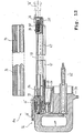
- FIG 15 is a partial view of the corotron arrangement in the operating position shown.
- the connecting element 30c is included firmly connected to the printer or copier housing 96.
- the outside of the connecting element 28c forms a sealing surface 29 and forms the inside of the connecting element 30c a sealing surface 31. If the sealing surfaces 29, 30 overlap touch, they allow a tight connection between the corotron assembly 12b of the ozone depletion unit.
- the ozone depletion unit sucks this in the corotron arrangement 12b resulting ozone-air mixture in the direction of the arrow Arrow P2.
- the corotron arrangement 12b with the connecting element 28c is moved in the direction of the arrow of arrow P2, take the Corotron arrangement and the connecting element the positions 12b 'and 28c'.
- FIG. 16 is a partial view of the corotron arrangement in FIG Maintenance position shown.
- the arrow P4 indicates an additional one Possibility of movement of the corotron arrangement 12b, which is given in the maintenance position.
Landscapes
- Physics & Mathematics (AREA)
- Engineering & Computer Science (AREA)
- Plasma & Fusion (AREA)
- General Physics & Mathematics (AREA)
- Electrostatic Charge, Transfer And Separation In Electrography (AREA)
Abstract
Description
- Figur 1
- einen Schwenkträger mit zwei Korotronanordnungen, wobei in einer Korotronanordnung ein Korotrondrahteinschub installiert ist,
- Figur 2
- ein Ausschnitt des in Figur 1 dargestellten Schwenkträgers mit der Korotronanordnung ohne Korotrondrahteinschub,
- Figur 3
- einen Schnitt durch die Korotronanordnung, einen Träger, die Spannungsversorgungseinheit und das Fotoleiterband,
- Figur 4
- den Korotrondrahteinschub mit Bruchlinien als Teilansicht,
- Figur 5
- das Verteilelement im Vollschnitt,
- Figur 6
- das Verteilelement des Korotrondrahteinschubs aus Figur 4 und 5 in einer um 90° gedrehten Ansicht,
- Figur 7
- das Aluminiumstrangprofil des Korotrondrahteinschubs mit dem Bandauflageelement als Auflager in einer Teilansicht,
- Figur 8
- die Teilansicht des Aluminiumstrangprofils aus Figur 7 in einer um 90° gedrehten Ansicht dieser Anordnung,
- Figur 9
- den Korotrondraht in dem Halteelement in einer teilgeschnittenen Darstellung sowie eine um 90° gedrehte Ansicht dieser Anordnung,
- Figur 10
- den Korotrondraht mit den Endstücken aus Figur 9 in einer ungeschnittenen Darstellung mit dem geschnitten dargestellten, vom Korotrondraht getrennten Halteelement sowie eine um 90° gedrehte Ansicht dieser Anordnung,
- Figur 11
- den Korotrondrahteinschub und den Korotrondraht in dem Halteelement,
- Figur 12
- den Korotrondrahteinschub mit dem eingesetzten Korotrondraht sowie das Halteelement aus Figur 11,
- Figur 13
- eine perspektivische Teilansicht der Korotronanordnung in Betriebslage,
- Figur 14
- eine perspektivische Teilansicht der Korotronanordnung in Wartungsposition,
- Figur 15
- eine Teilansicht der Korotronanordnung in Betriebslage, und
- Figur 16
- eine Teilansicht der Korotronanordnung in Wartungsposition.
- 10
- Schwenkträger
- 12a
- Korotronanordnung
- 12b
- Korotronanordnung
- 14a
- Korotrondrahteinschub
- 14b
- Korotrondrahteinschub
- 16a
- Einschubplatz für Korotrondrahteinschub
- 16b
- Einschubplatz für Korotrondrahteinschub
- 18a
- Schwenkträgerplatine
- 18b
- Schwenkträgerplatine
- 20
- Fotoleiterband
- 22a
- Spannungsversorgungseinheit
- 22b
- Spannungsversorgungseinheit
- 24a
- Netzteil zum Erzeugen der Korotronspannung
- 24b
- Netzteil zum Erzeugen der Korotronspannung
- 26a
- Netzteil zum Erzeugen der Schirmspannung
- 26b
- Netzteil zum Erzeugen der Schirmspannung
- 28a
- Verbindungselement Ozonabsaugung
- 28b
- Verbindungselement Ozonabsaugung
- 28c
- Verbindungselement Ozonabsaugung
- 29
- Dichtfläche
- 30a
- Verbindungselement Ozonabsaugung
- 30b
- Verbindungselement Ozonabsaugung
- 30c
- Verbindungselement Ozonabsaugung
- 31
- Dichtfläche
- 32a
- Halteklammer für Korotrondrahteinschub
- 32b
- Halteklammer für Korotrondrahteinschub
- 34
- Arretierungszapfen
- 36a
- Führungsschiene für Korotrondrahteinschub
- 36b
- Führungsschiene für Korotrondrahteinschub
- 38
- Blattfeder
- 40a
- Buchse Spannungsversorgungseinheit
- 40b
- Buchse Spannungsversorgungseinheit
- 42
- Träger mit H-förmigen Querschnitt
- 44
- Schrauben
- 46
- Reflektor
- 47
- Aluminiumstrangprofil
- 48
- Korotrondraht
- 49
- Schenkel
- 50
- Schlitze zur Ozonabsaugung
- 52
- Kanal zur Ozonabsaugung
- 54
- Bandauflageelement
- 56
- Verteilelement
- 58
- Stützelement des Korotrondrahteinschubs
- 60a
- Kontaktstift für Korotrondraht
- 60b
- Kontaktstift für Korotrondraht
- 60c
- Kontaktstift für Korotrondraht
- 62
- Kontaktstift Spannungsversorgung
- 64
- Keil zum Befestigen des Reflektors
- 66
- Arretierungselement zur Drahtverriegelung
- 68
- Befestigungselement
- 70
- Öffnungen des Stützelements
- 72
- Befestigungselement
- 74
- Halteelement
- 76
- Endstück Korotrondraht
- 78
- Endstück Korotrondraht
- 80
- Feder
- 82
- Buchse
- 84
- Zapfen
- 86
- Öffnung für Zapfen
- 88
- Führungselemente
- 90
- Öffnung für Korotrondraht
- 92
- gewölbte Schenkel des Halteelements
- 94
- Auflage Montagetisch
- 96
- Gestell
- P1
- Pfeil zur Laufrichtungsangabe des Fotoleiterbandes
- P2
- Absaugrichtung des Ozon-Luftgemischs
- P3
- Bewegungsrichtung in Wartungsposition
- P4
- Bewegungsmöglichkeit bei Wartungsposition
- P5
- Pfeil zum Einführen des Korotrondrahtes
- A
- Abstand Wartungsposition zur Betriebslage
- s
- Spiel
Claims (24)
- Anordnung für ein Korotron für elektrographische Prozesse, insbesondere in einem Drucker oder Kopierer,
mit einem Träger (42), in dem ein mit einer elektrischen Hochspannung versorgter Korotrondraht (48) angeordnet ist,
und mit mindestens einer Spannungsversorgungseinheit (22a, 22b), die die Hochspannung erzeugt,
wobei der Träger (42) die Spannungsversorgungseinheit (22a, 22b) aufnimmt, dadurch gekennzeichnet, dass der Korotrondraht (48) im Träger (42) in einem Korotrondrahteinschub (14a, 14b) angeordnet ist,
dass eine elektrische Verbindung zwischen der Spannungsversorgungseinheit (22a, 22b) und dem Korotrondrahteinschub (14a, 14b) mindestens einen Steckverbinder enthält, der beweglich angeordnet ist, so dass der Korotrondrahteinschub (14a, 14b) in verbundenem Zustand des Steckverbinders im Träger (42) bewegbar ist. - Anordnung nach Anspruch 1, dadurch gekennzeichnet, dass in dem Korotrondrahteinschub (14a, 14b) drei Korotrondrähte (48) angeordnet sind.
- Anordnung nach einem der Ansprüche 1 oder 2, dadurch gekennzeichnet, dass die Spannungsversorgungseinheit (22a, 22b) längs des Korotrondrahteinschubs (14a, 14b) angeordnet ist.
- Anordnung nach einem der vorhergehenden Ansprüche, dadurch gekennzeichnet, dass der Korotrondrahteinschub (14a, 14b) ein Reflektorelement (46) enthält, wobei das Reflektorelement (46) mit der Spannungsversorgungseinheit (22a, 22b) elektrisch verbunden ist.
- Anordnung nach Anspruch 4, dadurch gekennzeichnet, dass das Reflektorelement (46) aus einem Aluminiumstrangprofil besteht, das vorzugsweise hartverchromt ist.
- Anordnung nach einem der vorhergehenden Ansprüche, dadurch gekennzeichnet, dass der Korotrondrahteinschub (14a, 14b) in Führungselementen (36a, 36b) geführt ist, und dass die Führungselemente (36a, 36b) und der Korotrondrahteinschub (14a, 14b) ein Spiel (S) in Richtung einer parallelen Ebene zu den Korotrondrähten (48) haben.
- Anordnung nach einem der vorhergehenden Ansprüche, dadurch gekennzeichnet, dass die Federkraft von mindestens einer Feder (38) auf den Korotrondrahteinschub (14a, 14b) wirkt.
- Anordnung nach Anspruch 7, dadurch gekennzeichnet, dass die Feder (38) das Reflektorelement (46) elektrisch mit der Spannungsversorgungseinheit (22a, 22b) verbindet.
- Anordnung nach einem der vorhergehenden Ansprüche 4 bis 8, dadurch gekennzeichnet, dass das Reflektorelement (46) durch elektrisch isolierende Elemente (56, 58) gegenüber weiteren Elementen des Druckers oder Kopierers elektrisch isoliert angeordnet ist.
- Anordnung nach einem der Ansprüche 4 bis 9, dadurch gekennzeichnet, dass das Reflektorelement (46) Schlitze (50) enthält, durch die Gas, insbesondere ein Ozon- Luftgemisch, entweicht und/oder abgesaugt wird.
- Anordnung nach einem der Ansprüche 4 bis 10, dadurch gekennzeichnet, dass das Reflektorelement (46) aus einem Strangprofil besteht.
- Anordnung nach einem der Ansprüche 10 oder 11, dadurch gekennzeichnet, dass ein Kanal (52) zum Absaugen des Ozon- Luftgemisches durch Verbindungselemente (28a, 28b, 28c, 30a, 30b, 30c) mit einer Ozonvernichtungseinheit verbunden ist.
- Anordnung nach Anspruch 12, dadurch gekennzeichnet, dass die den Korotrondrähten (48) abgewandte Seite des Korotrondrahteinschubs (14a, 14b) und der Träger (42) den Kanal (52) bilden.
- Anordnung nach einem der Ansprüche 12 oder 13, dadurch gekennzeichnet, dass die Verbindungselemente (28a, 28b, 30a, 30b) an ihren Berührungsflächen Dichtelemente haben.
- Anordnung nach einem der Ansprüche 12 bis 14, dadurch gekennzeichnet, dass die Verbindungselemente (28c, 30c) Flächen haben, die einander überlappen.
- Anordnung nach einem der Ansprüche 12 bis 15, dadurch gekennzeichnet, dass die Verbindungselemente (28c, 30c) einen trapezförmigen Querschnitt haben.
- Anordnung nach einem der vorhergehenden Ansprüche, dadurch gekennzeichnet, dass mehrere Korotrondrahteinschübe (14a, 14b) vorgesehen sind, und dass jeder Korotrondrahteinschub (14a, 14b) von einer separaten Spannungsversorgungseinheit (22a, 22b) gespeist ist.
- Anordnung nach einem der vorhergehenden Ansprüche, dadurch gekennzeichnet, dass die Spannungsversorgungseinheit (22a, 22b) mindestens zwei Netzteile (24a, 24b, 26a, 26b) enthält, wobei ein Netzteil (24a, 24b) zur Versorgung des Korotrondrahtes und ein zweites Netzteil (26a, 26b) zur Versorgung des Reflektorelements (46) dient.
- Anordnung nach einem der vorhergehenden Ansprüche, dadurch gekennzeichnet, dass der Korotrondraht (48) mit einer Spannung, vorzugsweise im Bereich von 16 bis 20kV mit einer Frequenz im Bereich von 3 bis 5kHz, versorgt ist.
- Anordnung nach einem der Ansprüche 4 bis 19, dadurch gekennzeichnet, dass das Reflektorelement (46) mit einer Gleichspannung, vorzugsweise in einem Bereich von 3 bis 5 kV, versorgt ist.
- Anordnung nach einem der vorhergehenden Ansprüche, dadurch gekennzeichnet, dass am Korotrondrahteinschub (14a, 14b) mindestens ein Verteilelement (56) angebracht ist, das einerseits als mechanisches Betätigungselement (57) zum Hantieren des Korotrondrahteinschubs (14a,'14b) und andererseits einen Kontaktstift (62) eines elektrischen Steckverbinders zum Verbinden der Spannungsversorgungseinheit (22a, 22b) mit dem Korotrondrahteinschub (14a, 14b) enthält.
- Anordnung nach einem der vorhergehenden Ansprüche, dadurch gekennzeichnet, dass der Steckverbinder (40a, 40b, 62) an der Spannungsversorgungseinheit (22a, 22b) und/oder an dem Verteilelement (56) federnd gelagert ist.
- Anordnung nach einem der vorhergehenden Ansprüche, dadurch gekennzeichnet, dass der Träger (42) aus einem isolierenden Kunststoff besteht und einen H-förmigen Querschnitt hat,
und dass in der ersten rechteckigen Aussparung des H-förmigen Trägers (42) die Spannungsversorgungseinheit (22a, 22b) und in der zweiten rechteckigen Aussparung der Korotrondrahteinschub (14a, 14b) angeordnet ist. - Anordnung nach einem der vorhergehenden Ansprüche, dadurch gekennzeichnet, dass der Korotrondrahteinschub (14a, 14b) durch Führungselemente (36a, 36b) in dem Träger (42) geführt ist und der Träger (42) in einer schwenkbaren Anordnung (10) angeordnet ist.
Applications Claiming Priority (3)
| Application Number | Priority Date | Filing Date | Title |
|---|---|---|---|
| DE19957615A DE19957615A1 (de) | 1999-11-30 | 1999-11-30 | Korotron mit auf Auflagern aufliegendem Halteelement, einer Anordnung mit einer Spannungsversorgungseinheit sowie einer Anordnung zum Austauschen eines Korotrondrahtes |
| DE19957615 | 1999-11-30 | ||
| EP00983196A EP1234217B1 (de) | 1999-11-30 | 2000-11-30 | Korotron mit auf auflagern aufliegendem halteelement |
Related Parent Applications (1)
| Application Number | Title | Priority Date | Filing Date |
|---|---|---|---|
| EP00983196.7 Division | 2000-11-30 |
Publications (2)
| Publication Number | Publication Date |
|---|---|
| EP1450216A1 true EP1450216A1 (de) | 2004-08-25 |
| EP1450216B1 EP1450216B1 (de) | 2005-07-20 |
Family
ID=7930868
Family Applications (3)
| Application Number | Title | Priority Date | Filing Date |
|---|---|---|---|
| EP00983196A Expired - Lifetime EP1234217B1 (de) | 1999-11-30 | 2000-11-30 | Korotron mit auf auflagern aufliegendem halteelement |
| EP04011669A Expired - Lifetime EP1450216B1 (de) | 1999-11-30 | 2000-11-30 | Korotronanordung mit einer Spannungsversorgungseinheit |
| EP04011668A Expired - Lifetime EP1450215B1 (de) | 1999-11-30 | 2000-11-30 | Anordnung zum Austauschen eines Korotrondrahtes |
Family Applications Before (1)
| Application Number | Title | Priority Date | Filing Date |
|---|---|---|---|
| EP00983196A Expired - Lifetime EP1234217B1 (de) | 1999-11-30 | 2000-11-30 | Korotron mit auf auflagern aufliegendem halteelement |
Family Applications After (1)
| Application Number | Title | Priority Date | Filing Date |
|---|---|---|---|
| EP04011668A Expired - Lifetime EP1450215B1 (de) | 1999-11-30 | 2000-11-30 | Anordnung zum Austauschen eines Korotrondrahtes |
Country Status (4)
| Country | Link |
|---|---|
| US (1) | US6787774B1 (de) |
| EP (3) | EP1234217B1 (de) |
| DE (4) | DE19957615A1 (de) |
| WO (1) | WO2001040880A2 (de) |
Families Citing this family (6)
| Publication number | Priority date | Publication date | Assignee | Title |
|---|---|---|---|---|
| WO2004097723A1 (en) | 2003-04-29 | 2004-11-11 | Anoto Ip Lic Hb | Methods, apparatus, computer program and storage medium for position decoding |
| DE102004045351A1 (de) * | 2004-09-17 | 2006-04-06 | Ahlbrandt System Gmbh | Hochspannungselektrodeneinheit |
| US7432504B2 (en) * | 2005-09-27 | 2008-10-07 | Xerox Corporation | Dicorotron wire assembly removal and storage tool |
| US7420169B2 (en) * | 2005-09-27 | 2008-09-02 | Xerox Corporation | Dicorotron wire assembly removal-insertion tool |
| DE102009013972B4 (de) * | 2009-03-19 | 2010-12-23 | OCé PRINTING SYSTEMS GMBH | Corotroneinrichtung für ein über ein Führungsmittel bewegtes Element, insbesondere bei einem elektrografischen Druckgerät |
| JP6128751B2 (ja) * | 2012-05-11 | 2017-05-17 | キヤノン株式会社 | 画像形成装置 |
Citations (3)
| Publication number | Priority date | Publication date | Assignee | Title |
|---|---|---|---|---|
| US3685895A (en) * | 1970-05-18 | 1972-08-22 | Opto Graphics Inc | Electrophotographic charging easel |
| JPS58193560A (ja) * | 1982-05-07 | 1983-11-11 | Fuji Xerox Co Ltd | コロナ放電装置 |
| JPH05307312A (ja) * | 1992-04-30 | 1993-11-19 | Ricoh Co Ltd | 画像形成装置の高圧電源接続機構 |
Family Cites Families (16)
| Publication number | Priority date | Publication date | Assignee | Title |
|---|---|---|---|---|
| US4258258A (en) * | 1979-09-28 | 1981-03-24 | Xerox Corporation | Corona wire mounting device |
| JPS5729058A (en) * | 1980-07-30 | 1982-02-16 | Fuji Xerox Co Ltd | Charge for electrophotographic copier |
| JPS59218467A (ja) * | 1983-05-26 | 1984-12-08 | Fuji Xerox Co Ltd | 複写機の帯電装置 |
| JPS60220370A (ja) * | 1984-04-16 | 1985-11-05 | Fujitsu Ltd | 電子写真印刷装置用帯電器 |
| JPH01179960A (ja) * | 1988-01-11 | 1989-07-18 | Konica Corp | 画像形成装置 |
| JP2749609B2 (ja) * | 1989-01-31 | 1998-05-13 | 株式会社リコー | 画像形成装置 |
| US5216465A (en) * | 1990-03-19 | 1993-06-01 | Fuji Xerox Co., Ltd. | Print cartridge insertable into an image forming apparatus |
| US5128720A (en) * | 1991-01-18 | 1992-07-07 | Eastman Kodak Company | Device for collecting contamination products and ozone from a corona charger |
| JPH0511160U (ja) * | 1991-07-25 | 1993-02-12 | 旭光学工業株式会社 | コロナチヤージヤのグリツト位置決め構造 |
| JPH05127489A (ja) * | 1991-10-30 | 1993-05-25 | Ricoh Co Ltd | 画像形成装置 |
| US5335050A (en) * | 1993-09-13 | 1994-08-02 | Xerox Corporation | Adjustable support assembly |
| US5449906A (en) * | 1994-01-03 | 1995-09-12 | Xerox Corporation | Corona generating electrode replacement tool |
| US5666605A (en) * | 1994-10-11 | 1997-09-09 | Konica Corporation | Charging unit |
| JPH08146715A (ja) * | 1994-11-15 | 1996-06-07 | Canon Inc | 画像形成装置 |
| JP3457775B2 (ja) * | 1995-08-31 | 2003-10-20 | 株式会社リコー | 電子写真装置 |
| US5812359A (en) * | 1997-04-11 | 1998-09-22 | Xerox Corporation | Method and apparatus for lightweight corona device shield mounting |
-
1999
- 1999-11-30 DE DE19957615A patent/DE19957615A1/de not_active Ceased
-
2000
- 2000-11-30 WO PCT/EP2000/012045 patent/WO2001040880A2/de not_active Ceased
- 2000-11-30 EP EP00983196A patent/EP1234217B1/de not_active Expired - Lifetime
- 2000-11-30 DE DE50010787T patent/DE50010787D1/de not_active Expired - Lifetime
- 2000-11-30 EP EP04011669A patent/EP1450216B1/de not_active Expired - Lifetime
- 2000-11-30 US US10/148,377 patent/US6787774B1/en not_active Expired - Fee Related
- 2000-11-30 DE DE50011140T patent/DE50011140D1/de not_active Expired - Lifetime
- 2000-11-30 DE DE50009064T patent/DE50009064D1/de not_active Expired - Lifetime
- 2000-11-30 EP EP04011668A patent/EP1450215B1/de not_active Expired - Lifetime
Patent Citations (3)
| Publication number | Priority date | Publication date | Assignee | Title |
|---|---|---|---|---|
| US3685895A (en) * | 1970-05-18 | 1972-08-22 | Opto Graphics Inc | Electrophotographic charging easel |
| JPS58193560A (ja) * | 1982-05-07 | 1983-11-11 | Fuji Xerox Co Ltd | コロナ放電装置 |
| JPH05307312A (ja) * | 1992-04-30 | 1993-11-19 | Ricoh Co Ltd | 画像形成装置の高圧電源接続機構 |
Non-Patent Citations (3)
| Title |
|---|
| PATENT ABSTRACTS OF JAPAN vol. 0080, no. 42 (P - 256) 23 February 1984 (1984-02-23) * |
| PATENT ABSTRACTS OF JAPAN vol. 0134, no. 60 (P - 946) 18 October 1989 (1989-10-18) * |
| PATENT ABSTRACTS OF JAPAN vol. 0181, no. 21 (P - 1700) 25 February 1994 (1994-02-25) * |
Also Published As
| Publication number | Publication date |
|---|---|
| US6787774B1 (en) | 2004-09-07 |
| DE19957615A1 (de) | 2001-06-13 |
| EP1450215A1 (de) | 2004-08-25 |
| DE50009064D1 (de) | 2005-01-27 |
| EP1234217A2 (de) | 2002-08-28 |
| DE50011140D1 (de) | 2005-10-13 |
| WO2001040880A2 (de) | 2001-06-07 |
| EP1450215B1 (de) | 2005-09-07 |
| EP1234217B1 (de) | 2004-12-22 |
| WO2001040880A3 (de) | 2002-03-28 |
| EP1450216B1 (de) | 2005-07-20 |
| DE50010787D1 (de) | 2005-08-25 |
Similar Documents
| Publication | Publication Date | Title |
|---|---|---|
| DE2742643C2 (de) | Modulaufbau für ein elektronisches Datenverarbeitungsgerät | |
| DE69008812T2 (de) | Potentialausgleichsstruktur für in einem Computer verwandte, auf Schienen montierte Einrichtungen. | |
| DE68911607T2 (de) | Hochfrequenzverbindungs- und Abschirmungssystem. | |
| DE2932883A1 (de) | Aufnahmevorrichtung fuer geraeteeinheiten der elektrischen signaluebertragungstechnik | |
| DE60210365T2 (de) | Elektrischer Verbinder mit Schutzblende und Zusammenbau | |
| DE3685792T2 (de) | Stromversorgungsanordnung. | |
| EP0412331B1 (de) | Vorrichtung zur elektrischen Verbindung von Abschirmungen mehrpoliger Stecker mit der Erdpotentialschicht einer Verdrahtungsplatte | |
| DE4315499C2 (de) | Profilleiste zur Befestigung von Spannbahnen und zum Hängen von Objekten | |
| DE19857624A1 (de) | Verbinderanordnung für flache Schaltungseinrichtungen | |
| EP1450216B1 (de) | Korotronanordung mit einer Spannungsversorgungseinheit | |
| DE69500587T2 (de) | Verbinder für Leiterplatten | |
| DE3313970A1 (de) | Vorrichtung zum sicheren herstellen von elektrisch leitenden verbindungen zwischen gehaeuseteilen eines gehaeuses | |
| DE3546011A1 (de) | Gasisolierte, elektrische vorrichtung | |
| DE102006040593A1 (de) | Einstellbare Elektrodenanordnung zur Verwendung bei der Behandlung von Substraten unterschiedlicher Breite in einem Plasma-Behandlungssystem | |
| DE69409973T2 (de) | Spannbefestigungssystem für eine Vorrichtung zur Erzeugung von Coronaentladung | |
| DE102022200395A1 (de) | Antriebsanordnung | |
| DE3137396C2 (de) | Vorrichtung zur Arbeitserdung in einer elektrischen Anlage | |
| DE69610604T2 (de) | Abschirmvorrichtung zum Schutz gegen elektromagnetische Störungen einer Mehrzahl von Kabeln | |
| DD235769A1 (de) | Halterung fuer elektrische geraete in gerasteter einschubtechnik | |
| DE966031C (de) | Steckvorrichtung fuer Roehrenschaltelemente | |
| DE102023104635A1 (de) | Beleuchtungsvorrichtung sowie bausatz | |
| DE3340243A1 (de) | Vorrichtung zum pruefen von leiterplatten | |
| DE102019109666A1 (de) | System zur Realisierung einer Leuchte | |
| DE202022102161U1 (de) | Sammelschienenverbinder | |
| DE202024100586U1 (de) | Elektrifizierte Führungen für Beleuchtungssysteme mit mehreren Anschlussaussparungen |
Legal Events
| Date | Code | Title | Description |
|---|---|---|---|
| PUAI | Public reference made under article 153(3) epc to a published international application that has entered the european phase |
Free format text: ORIGINAL CODE: 0009012 |
|
| 17P | Request for examination filed |
Effective date: 20040517 |
|
| AC | Divisional application: reference to earlier application |
Ref document number: 1234217 Country of ref document: EP Kind code of ref document: P |
|
| AK | Designated contracting states |
Kind code of ref document: A1 Designated state(s): BE DE FR GB |
|
| GRAP | Despatch of communication of intention to grant a patent |
Free format text: ORIGINAL CODE: EPIDOSNIGR1 |
|
| GRAS | Grant fee paid |
Free format text: ORIGINAL CODE: EPIDOSNIGR3 |
|
| AKX | Designation fees paid |
Designated state(s): BE DE FR GB |
|
| GRAA | (expected) grant |
Free format text: ORIGINAL CODE: 0009210 |
|
| AC | Divisional application: reference to earlier application |
Ref document number: 1234217 Country of ref document: EP Kind code of ref document: P |
|
| AK | Designated contracting states |
Kind code of ref document: B1 Designated state(s): BE DE FR GB |
|
| REG | Reference to a national code |
Ref country code: GB Ref legal event code: FG4D Free format text: NOT ENGLISH |
|
| REF | Corresponds to: |
Ref document number: 50010787 Country of ref document: DE Date of ref document: 20050825 Kind code of ref document: P |
|
| GBT | Gb: translation of ep patent filed (gb section 77(6)(a)/1977) |
Effective date: 20051010 |
|
| PG25 | Lapsed in a contracting state [announced via postgrant information from national office to epo] |
Ref country code: BE Free format text: LAPSE BECAUSE OF NON-PAYMENT OF DUE FEES Effective date: 20051130 |
|
| ET | Fr: translation filed | ||
| PLBE | No opposition filed within time limit |
Free format text: ORIGINAL CODE: 0009261 |
|
| STAA | Information on the status of an ep patent application or granted ep patent |
Free format text: STATUS: NO OPPOSITION FILED WITHIN TIME LIMIT |
|
| 26N | No opposition filed |
Effective date: 20060421 |
|
| BERE | Be: lapsed |
Owner name: OCE PRINTING SYSTEMS G.M.B.H. Effective date: 20051130 |
|
| PGFP | Annual fee paid to national office [announced via postgrant information from national office to epo] |
Ref country code: GB Payment date: 20101126 Year of fee payment: 11 |
|
| PGFP | Annual fee paid to national office [announced via postgrant information from national office to epo] |
Ref country code: FR Payment date: 20111125 Year of fee payment: 12 |
|
| GBPC | Gb: european patent ceased through non-payment of renewal fee |
Effective date: 20121130 |
|
| REG | Reference to a national code |
Ref country code: DE Ref legal event code: R082 Ref document number: 50010787 Country of ref document: DE Representative=s name: PATENTANWAELTE SCHAUMBURG, THOENES, THURN, LAN, DE |
|
| REG | Reference to a national code |
Ref country code: FR Ref legal event code: ST Effective date: 20130731 |
|
| REG | Reference to a national code |
Ref country code: DE Ref legal event code: R081 Ref document number: 50010787 Country of ref document: DE Owner name: OCE PRINTING SYSTEMS GMBH & CO. KG, DE Free format text: FORMER OWNER: OCE PRINTING SYSTEMS GMBH, 85586 POING, DE Effective date: 20130819 Ref country code: DE Ref legal event code: R082 Ref document number: 50010787 Country of ref document: DE Representative=s name: PATENTANWAELTE SCHAUMBURG, THOENES, THURN, LAN, DE Effective date: 20130819 Ref country code: DE Ref legal event code: R082 Ref document number: 50010787 Country of ref document: DE Representative=s name: SCHAUMBURG & PARTNER PATENTANWAELTE GBR, DE Effective date: 20130819 |
|
| PG25 | Lapsed in a contracting state [announced via postgrant information from national office to epo] |
Ref country code: GB Free format text: LAPSE BECAUSE OF NON-PAYMENT OF DUE FEES Effective date: 20121130 Ref country code: FR Free format text: LAPSE BECAUSE OF NON-PAYMENT OF DUE FEES Effective date: 20121130 |
|
| PGFP | Annual fee paid to national office [announced via postgrant information from national office to epo] |
Ref country code: DE Payment date: 20140128 Year of fee payment: 14 |
|
| REG | Reference to a national code |
Ref country code: DE Ref legal event code: R082 Ref document number: 50010787 Country of ref document: DE Representative=s name: SCHAUMBURG & PARTNER PATENTANWAELTE GBR, DE |
|
| REG | Reference to a national code |
Ref country code: DE Ref legal event code: R119 Ref document number: 50010787 Country of ref document: DE |
|
| PG25 | Lapsed in a contracting state [announced via postgrant information from national office to epo] |
Ref country code: DE Free format text: LAPSE BECAUSE OF NON-PAYMENT OF DUE FEES Effective date: 20150602 |