EP1449717A2 - Blinkerrücksetzung und Verfahren hierfür - Google Patents
Blinkerrücksetzung und Verfahren hierfür Download PDFInfo
- Publication number
- EP1449717A2 EP1449717A2 EP04400006A EP04400006A EP1449717A2 EP 1449717 A2 EP1449717 A2 EP 1449717A2 EP 04400006 A EP04400006 A EP 04400006A EP 04400006 A EP04400006 A EP 04400006A EP 1449717 A2 EP1449717 A2 EP 1449717A2
- Authority
- EP
- European Patent Office
- Prior art keywords
- reset
- turn signal
- transmitter
- receiver
- steering wheel
- Prior art date
- Legal status (The legal status is an assumption and is not a legal conclusion. Google has not performed a legal analysis and makes no representation as to the accuracy of the status listed.)
- Withdrawn
Links
Images
Classifications
-
- B—PERFORMING OPERATIONS; TRANSPORTING
- B60—VEHICLES IN GENERAL
- B60Q—ARRANGEMENT OF SIGNALLING OR LIGHTING DEVICES, THE MOUNTING OR SUPPORTING THEREOF OR CIRCUITS THEREFOR, FOR VEHICLES IN GENERAL
- B60Q1/00—Arrangement of optical signalling or lighting devices, the mounting or supporting thereof or circuits therefor
- B60Q1/26—Arrangement of optical signalling or lighting devices, the mounting or supporting thereof or circuits therefor the devices being primarily intended to indicate the vehicle, or parts thereof, or to give signals, to other traffic
- B60Q1/34—Arrangement of optical signalling or lighting devices, the mounting or supporting thereof or circuits therefor the devices being primarily intended to indicate the vehicle, or parts thereof, or to give signals, to other traffic for indicating change of drive direction
- B60Q1/40—Arrangement of optical signalling or lighting devices, the mounting or supporting thereof or circuits therefor the devices being primarily intended to indicate the vehicle, or parts thereof, or to give signals, to other traffic for indicating change of drive direction having mechanical, electric or electronic automatic return to inoperative position
Definitions
- the invention relates to a turn signal reset and a Procedure for resetting a set turn signal.
- Such turn signal resets and associated procedures are known for example from DE 100 37 586 A1.
- This Trigger means for example in the form of cams can be trained, press after setting the Turn signal when turning the steering wheel of the rotary movement of the Steering wheel not following reset means that a reset of the turn signal.
- the known, mechanical turn signal reset have the Disadvantage that noises when actuating the release means occur. In addition, they are very susceptible to faults because Ingress of unwanted media, such as Dust or dirt particles, pressing the Trigger agent can be adversely affected. Known, mechanical turn signal resets are also subject to one Wear.
- the present invention is therefore based on the object based on a turn signal reset and an associated one Provide procedures that are as extensive as possible works silently and is not susceptible to contamination is. In addition, one should work as wear-free as possible Turn signal reset are provided.
- a turn signal reset which is characterized in that the resetting means actuated by the release means, movably mounted Switching part with at least one transmitter respectively Receiver and at least one, opposite the switching part stationary, with the transmitter respectively Receiver corresponding to the contactless receiver or transmitters, the triggering means when turning the steering wheel, actuate the switching part and thereby a transmitter in the coverage area of a Receiver moves and a signal to reset the Blinkers is generated. Because the at least one Transmitter with the at least one receiver without contact corresponds, no noise occurs. It also occurs due to the non-contact arrangement between the Receiver and transmitter no wear and tear leading to a permanently very precisely working and to a high Indicator reset service life.
- a particularly advantageous embodiment of the invention arises when the switching part is a transmitter and if two fixed receivers are provided such that the transmitter when turning the Steering wheel in one direction in the detection area of the a transmitter and when turning in the other direction in the Detection range of the other transmitter can reach.
- a Such embodiment has the advantage that the Direction of rotation of the steering wheel can be detected, with a The turn signal is only reset when the steering wheel is turned back and not when the steering wheel is a full Turn overturned. This ensures that the Turn signal is only reset when the steering wheel is rotated against the original direction of rotation.
- the turn signal is not reset.
- magnetic signals are used in particular, whereby Permanent magnets in connection with magnetic field sensors, such as for example Hall elements can be used.
- Senders and / or receivers can also, for example LEDs or solenoids are used.
- the switching part can according to the invention as a sliding part or be designed as a swivel part.
- a sliding part is slidably supported along a preferably straight line; a pivoting part can be pivoted about a fixed pivot axis.
- Resetting means can in particular be spring elements that keep the switching part in the neutral starting position.
- a particularly preferred embodiment of the invention results when the resetting means at least one Evaluation unit include that of the at least one Transmitter received signals and the respective Turn signal depending on the signals received resets.
- the evaluation unit therefore initiates Reset the respective set of turn signals when the reset means or the recipients have received the corresponding signal.
- the evaluation unit can, for example, a transistor stage or a flip-flop include.
- a turn signal switch can, for example be a well-known steering column switch by the Vehicle driver can be actuated
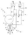
- the turn signal reset 10 includes a rotational movement of one, not shown Steering wheel following trigger 12, for example a steering column 14 following the rotational movement can be.
- the axis of rotation of the steering column 14 respectively of the steering wheel, not shown, is 16 characterized.
- the trigger means 12 can Invention as itself in the axial or radial direction extending cams may be formed.
- the trigger means 12 do not correspond to the rotation of the steering wheel following reset means 16.
- Turn signal via, for example, a not shown Actuator switches are set, set the Reset means 16 when actuated by the trigger means 12 the turn signal back.
- the reset means 16 can be actuated by the triggering means 12 to a Swivel axis 18, pivotally mounted switching part 20 on.
- the switching part 20 has its axis 18 facing away from a transmitter 22, which is in the neutral Starting position of the switching part 22 in the middle between two arranged stationary with respect to the switching part 20 Receivers 24, 26 is arranged.
- the transmitter 22 corresponds to the receivers 24, 26 without contact.
- the triggering means 12 and the switching part 20 are of this type arranged that the trigger means 12 when rotating the Steering wheel or the steering column 14, the switching part 20 from its neutral starting position in one direction Deflect double arrow 28. Depending on the direction of rotation of the The steering wheel is thereby the transmitter 22 either in the Detection range of the receiver 24 or in the Detection area of the receiver 26 moves. This will generates a signal 30 or 32 that one Evaluation unit 34 is supplied. So that the switching part 20th after deflection by the steering wheel-side release means 12 is moved back to its original position Reset means 36 are provided in the form of spring elements.
- a permanent magnet can be used as the transmitter 22, for example Find use.
- the receivers 24, 26 are then as Magnetic field sensors designed, for example as Hall sensors or Hall IC's.
- other pairs of transmitters and receivers are also used, which in addition to magnetic signals are optical or electrical Send and receive signals.
- the evaluation unit 34 has two control elements 38, 40 on, the control element 38 for controlling the right one Blinkers (signal 42) and the control element 40 for Control of the left turn signal (signal 44) is used.
- the evaluation unit 34 also signals 46, 48 one Indicator switch not shown supplied. by virtue of of the input signals 46, 48 set the control elements 38, 40 the respective turn signal via the output signals 42, 44. If the steering wheel is turned back after the turn signal has been set, from the transmitter 22 and the receivers 24, 26 corresponding reset signal 30, 32 generated that the Evaluation unit 24 is supplied. The controls 38, 40 then cause a reset of the right one or left turn signal (signal 42 or 44).
- the direction of rotation of the steering wheel can be recognized.
- the turn signal will only be reset if that Steering wheel is actually turned back, and not when that Steering wheel by turning the steering wheel further in the the original direction of rotation is turned.
- the evaluation unit 34 also sees the as input signals Signals 46 'and 48' in front of it, which then do not Turn signal switches shown are generated when by for example, tapping the actuator of the Turn signal switch not flashing continuously, but on only one flash should be generated. On such flashing is for example for changing lanes, especially on the highway, helpful.
Landscapes
- Engineering & Computer Science (AREA)
- Mechanical Engineering (AREA)
- Lighting Device Outwards From Vehicle And Optical Signal (AREA)
Abstract
Description
Claims (10)
- Blinkerrücksetzung (10) zum Rücksetzen eines gesetzten Fahrzeugblinkers, mit der Drehbewegung des Lenkrads folgenden Auslösemitteln (12) und mit der Drehbewegung des Lenkrads nicht folgenden Rücksetzmitteln (16), wobei beim Rückdrehen des Lenkrades die Rücksetzmittel (16) von den Auslösemitteln (12) betätigt werden und der gesetzte Blinker zurückgesetzt wird, dadurch gekennzeichnet, dass die Rücksetzmittel (16) ein von den Auslösemitteln (12) betätigbares, beweglich gelagertes Schaltteil (20) mit wenigstens einem Sender (22) bzw. Empfänger und wenigstens einen gegenüber dem Schaltteil (20) ortsfest angeordneten, mit dem Sender (22) bzw. Empfänger berührungslos korrespondierenden Empfänger (24, 26) bzw. Sender umfassen, wobei die Auslösemittel (12) beim Drehen des Lenkrades das Schaltteil (20) betätigen und dadurch ein Sender (22) in den Erfassungsbereich eines Empfängers (24, 26) bewegt und ein Signal zur Rücksetzung des Blinkers generiert wird.
- Blinkerrücksetzung (10) nach Anspruch 1, dadurch gekennzeichnet, dass das Schaltteil (20) einen Sender (22) aufweist und dass zwei ortsfest angeordnete Empfänger derart vorgesehen sind, dass der Sender (22) beim Drehen des Lenkrades in die eine Richtung in den Erfassungsbereich des einen Senders (24) und beim Drehen in die andere Richtung in den Erfassungsbereich des anderen Senders (26) gelangen kann.
- Blinkerrücksetzung (10) nach Anspruch 1 oder 2, dadurch gekennzeichnet, dass der wenigstens eine Sender (22) elektrische, magnetische und/oder optische Signale sendet oder reflektiert und dass der wenigstens eine Empfänger (24, 26) diese Signale empfängt.
- Blinkerrücksetzung (10) nach Anspruch 1, 2 oder 3, dadurch gekennzeichnet, dass das Schaltteil (20) als Schiebeteil oder als Schwenkteil ausgebildet ist.
- Blinkerrücksetzung (10) nach einem der vorhergehenden Ansprüche, dadurch gekennzeichnet, dass Rückstellmittel (36) vorgesehen sind, die das Schaltteil (20) nach dem Bewegen durch die Auslösemittel (12) wieder in eine neutrale Ausgangslage rückstellen.
- Blinkerrücksetzung (10) nach einem der vorhergehenden Ansprüche, dadurch gekennzeichnet, dass die Rücksetzmittel (16) wenigstens eine Auswerteeinheit (34) umfassen, die die empfangenen Signale auswertet und den jeweils gesetzten Blinker in Abhängigkeit von den empfangenen Signalen rücksetzt.
- Blinkerrücksetzung (10) nach Anspruch 6, dadurch gekennzeichnet, dass die Auswerteeinheit (34) den jeweiligen Blinker in Abhängigkeit von Signalen (22, 24) setzt, die von einem Blinkerschalter generiert und der Auswerteinheit (34) zugeführt werden.
- Verfahren zum Rücksetzen eines gesetzten Fahrzeugblinkers, wobei der Drehbewegung des Lenkrads folgende Auslösemittel (12) und der Drehbewegung des Lenkrads nicht folgende Rücksetzmittel (16) vorgesehen sind, und wobei beim Rückdrehen des Lenkrades die Rücksetzmittel (16) von den Auslösemitteln (12) betätigt werden und der gesetzte Blinker zurückgesetzt wird, dadurch gekennzeichnet, dass die Rücksetzmittel (16) ein von den Auslösemitteln (12) betätigbares, beweglich gelagertes Schaltteil (20) mit wenigstens einem Sender (22) bzw. Empfänger und wenigstens einen gegenüber dem Schaltteil (22) ortsfest angeordneten, mit dem Sender (22) bzw. Empfänger berührungslos korrespondierenden Empfänger (24, 26) bzw. Sender umfassen, wobei die Auslösemittel (12) beim Drehen des Lenkrades das Schaltteil betätigen und dadurch ein Sender (22) in den Erfassungsbereich eines Empfängers (24, 26) bewegt und ein Signal zur Rücksetzung des Blinkers generiert wird.
- Verfahren zum Betreiben einer Blinkerrücksetzung (10) nach einem der Ansprüche 1 bis 7.
- Auswerteeinheit (34) für eine Blinkerrücksetzung (10) nach einem der Ansprüche 5 bis 7 und/oder zur Anwendung in einem Verfahren nach Anspruch 8 oder 9.
Applications Claiming Priority (2)
| Application Number | Priority Date | Filing Date | Title |
|---|---|---|---|
| DE10308474 | 2003-02-20 | ||
| DE10308474.6A DE10308474B4 (de) | 2003-02-20 | 2003-02-20 | Blinkerrücksetzung und Verfahren hierfür |
Publications (2)
| Publication Number | Publication Date |
|---|---|
| EP1449717A2 true EP1449717A2 (de) | 2004-08-25 |
| EP1449717A3 EP1449717A3 (de) | 2006-03-22 |
Family
ID=32731138
Family Applications (1)
| Application Number | Title | Priority Date | Filing Date |
|---|---|---|---|
| EP04400006A Withdrawn EP1449717A3 (de) | 2003-02-20 | 2004-02-20 | Blinkerrücksetzung und Verfahren hierfür |
Country Status (2)
| Country | Link |
|---|---|
| EP (1) | EP1449717A3 (de) |
| DE (1) | DE10308474B4 (de) |
Cited By (1)
| Publication number | Priority date | Publication date | Assignee | Title |
|---|---|---|---|---|
| CN106427770A (zh) * | 2016-11-01 | 2017-02-22 | 南京依维柯汽车有限公司 | 一种集成螺旋电缆的自动回位探针机构及其工作方法 |
Family Cites Families (8)
| Publication number | Priority date | Publication date | Assignee | Title |
|---|---|---|---|---|
| FR2403238A1 (fr) * | 1977-09-14 | 1979-04-13 | Renault | Dispositif electromecanique de rappel automatique de clignotant electronique place sur l'arbre de direction d'un vehicule automobile |
| JPS54144193A (en) * | 1978-05-01 | 1979-11-10 | Tokai Rika Co Ltd | Automotive direction indicator |
| DE2913008C3 (de) * | 1979-03-31 | 1984-10-25 | Fa. Leopold Kostal, 5880 Lüdenscheid | Einrichtung zur selbsttätigen Rückstellung eines Fahrtrichtungsanzeigers bei Kraftfahrzeugen |
| JPS5668165U (de) * | 1979-10-31 | 1981-06-06 | ||
| DE3221434A1 (de) * | 1982-06-07 | 1983-12-08 | Franz Kirsten Elektrotechnische Spezialfabrik, 6530 Bingen | Schalteinrichtung zum ansteuern von blinklampen in kraftfahrzeugen |
| FR2539360B1 (fr) * | 1983-01-14 | 1987-09-18 | Dav Ind | Dispositif pour la deconnexion d'un organe indicateur de direction d'un vehicule automobile |
| DE19914352A1 (de) | 1999-03-30 | 2000-10-05 | Valeo Schalter & Sensoren Gmbh | Elektrischer Schalter, insbesondere Lenkstockschalter für ein Kraftfahrzeug |
| DE10037586C2 (de) | 2000-08-02 | 2003-06-18 | Valeo Schalter & Sensoren Gmbh | Rückstellvorrichtung für einen Blinkerschalter in Kraftfahrzeugen |
-
2003
- 2003-02-20 DE DE10308474.6A patent/DE10308474B4/de not_active Expired - Lifetime
-
2004
- 2004-02-20 EP EP04400006A patent/EP1449717A3/de not_active Withdrawn
Cited By (1)
| Publication number | Priority date | Publication date | Assignee | Title |
|---|---|---|---|---|
| CN106427770A (zh) * | 2016-11-01 | 2017-02-22 | 南京依维柯汽车有限公司 | 一种集成螺旋电缆的自动回位探针机构及其工作方法 |
Also Published As
| Publication number | Publication date |
|---|---|
| DE10308474B4 (de) | 2023-06-01 |
| DE10308474A1 (de) | 2004-09-02 |
| EP1449717A3 (de) | 2006-03-22 |
Similar Documents
| Publication | Publication Date | Title |
|---|---|---|
| EP3594044B1 (de) | Kapazitives kraftfahrzeugbediensystem | |
| EP1167109B1 (de) | Anwahlschalteinrichtung | |
| EP1961025B1 (de) | Bedienknopf mit integrierter funktionalität | |
| EP2099646B1 (de) | Lenkstockschalter für kraftfahrzeuge | |
| EP1994541A2 (de) | Schalter, insbesondere fahrzeugschalter, auswerteeinheit hierfür und zugehörige schaltereinheit | |
| DE102011052027A1 (de) | Schaltbereichsdetektiervorrichtung und schaltvorrichtung mit derselben | |
| WO2019063039A1 (de) | Kraftfahrzeugschloss für ein bewegliches teil eines kraftfahrzeugs | |
| DE102013007233A1 (de) | Elektrische Schalteinrichtung für ein Kraftfahrzeug | |
| DE4123857C2 (de) | ||
| DE19622493C5 (de) | Schalteinrichtung für Kraftfahrzeuge | |
| DE102019133791A1 (de) | Parametrierbares Steuergerät für eine Anhängekupplung | |
| DE102008034602B3 (de) | Translatorisch betätigter Joystick | |
| DE10308474B4 (de) | Blinkerrücksetzung und Verfahren hierfür | |
| DE19947406C1 (de) | Einstelleinrichtung | |
| EP3378701A1 (de) | Verfahren und vorrichtung zur ansteuerung von fernlichtfunktionen eines kraftfahrzeuges | |
| DE102016101024A1 (de) | Bedienelement mit verbesserter Fehlfunktionsdetektion | |
| DE102005005185B4 (de) | Schaltanordnung für ein Schaltelement zum Öffnen und Schließen eines Fahrzeugflügels | |
| DE102006030746A1 (de) | Hebelschalter für einen Lenkstock eines Kraftfahrzeugs | |
| EP2217470B1 (de) | Scheinwerfer mit einer messeinrichtung zur erfassung der lage eines lichtmoduls | |
| DE10308475A1 (de) | Blinkerrücksetzung und Verfahren hierfür | |
| EP3941787B1 (de) | Lenkstockschalter für ein fahrzeug | |
| DE102006018518A1 (de) | Bedienknopf mit integrierter Funktionalität | |
| DE102007035289A1 (de) | Kraftfahrzeug umfassend eine Beleuchtungseinrichtung mit manuell sowie über ein Assistenzsystem automatisch zuschaltbarem Fernlicht | |
| DE2608865A1 (de) | Einrichtung zum ausschalten eines fahrtrichtungsanzeigers bei einem kraftfahrzeug nach einer kurvenfahrt | |
| DE102005055305B4 (de) | Bedienelement mit Wake-up-Funktionalität |
Legal Events
| Date | Code | Title | Description |
|---|---|---|---|
| PUAI | Public reference made under article 153(3) epc to a published international application that has entered the european phase |
Free format text: ORIGINAL CODE: 0009012 |
|
| AK | Designated contracting states |
Kind code of ref document: A2 Designated state(s): AT BE BG CH CY CZ DE DK EE ES FI FR GB GR HU IE IT LI LU MC NL PT RO SE SI SK TR |
|
| AX | Request for extension of the european patent |
Extension state: AL HR LT LV MK |
|
| PUAL | Search report despatched |
Free format text: ORIGINAL CODE: 0009013 |
|
| AK | Designated contracting states |
Kind code of ref document: A3 Designated state(s): AT BE BG CH CY CZ DE DK EE ES FI FR GB GR HU IE IT LI LU MC NL PT RO SE SI SK TR |
|
| AX | Request for extension of the european patent |
Extension state: AL LT LV MK |
|
| AKX | Designation fees paid | ||
| STAA | Information on the status of an ep patent application or granted ep patent |
Free format text: STATUS: THE APPLICATION IS DEEMED TO BE WITHDRAWN |
|
| 18D | Application deemed to be withdrawn |
Effective date: 20060923 |
|
| REG | Reference to a national code |
Ref country code: DE Ref legal event code: 8566 |