EP3594044B1 - Kapazitives kraftfahrzeugbediensystem - Google Patents
Kapazitives kraftfahrzeugbediensystem Download PDFInfo
- Publication number
- EP3594044B1 EP3594044B1 EP19184508.0A EP19184508A EP3594044B1 EP 3594044 B1 EP3594044 B1 EP 3594044B1 EP 19184508 A EP19184508 A EP 19184508A EP 3594044 B1 EP3594044 B1 EP 3594044B1
- Authority
- EP
- European Patent Office
- Prior art keywords
- pressure
- capacitive
- actuation device
- motor vehicle
- operating system
- Prior art date
- Legal status (The legal status is an assumption and is not a legal conclusion. Google has not performed a legal analysis and makes no representation as to the accuracy of the status listed.)
- Revoked
Links
Images


Classifications
-
- G—PHYSICS
- G06—COMPUTING OR CALCULATING; COUNTING
- G06F—ELECTRIC DIGITAL DATA PROCESSING
- G06F3/00—Input arrangements for transferring data to be processed into a form capable of being handled by the computer; Output arrangements for transferring data from processing unit to output unit, e.g. interface arrangements
- G06F3/01—Input arrangements or combined input and output arrangements for interaction between user and computer
- G06F3/016—Input arrangements with force or tactile feedback as computer generated output to the user
-
- H—ELECTRICITY
- H03—ELECTRONIC CIRCUITRY
- H03K—PULSE TECHNIQUE
- H03K17/00—Electronic switching or gating, i.e. not by contact-making and –breaking
- H03K17/94—Electronic switching or gating, i.e. not by contact-making and –breaking characterised by the way in which the control signals are generated
- H03K17/96—Touch switches
- H03K17/962—Capacitive touch switches
-
- B—PERFORMING OPERATIONS; TRANSPORTING
- B60—VEHICLES IN GENERAL
- B60K—ARRANGEMENT OR MOUNTING OF PROPULSION UNITS OR OF TRANSMISSIONS IN VEHICLES; ARRANGEMENT OR MOUNTING OF PLURAL DIVERSE PRIME-MOVERS IN VEHICLES; AUXILIARY DRIVES FOR VEHICLES; INSTRUMENTATION OR DASHBOARDS FOR VEHICLES; ARRANGEMENTS IN CONNECTION WITH COOLING, AIR INTAKE, GAS EXHAUST OR FUEL SUPPLY OF PROPULSION UNITS IN VEHICLES
- B60K35/00—Instruments specially adapted for vehicles; Arrangement of instruments in or on vehicles
- B60K35/10—Input arrangements, i.e. from user to vehicle, associated with vehicle functions or specially adapted therefor
-
- B—PERFORMING OPERATIONS; TRANSPORTING
- B60—VEHICLES IN GENERAL
- B60K—ARRANGEMENT OR MOUNTING OF PROPULSION UNITS OR OF TRANSMISSIONS IN VEHICLES; ARRANGEMENT OR MOUNTING OF PLURAL DIVERSE PRIME-MOVERS IN VEHICLES; AUXILIARY DRIVES FOR VEHICLES; INSTRUMENTATION OR DASHBOARDS FOR VEHICLES; ARRANGEMENTS IN CONNECTION WITH COOLING, AIR INTAKE, GAS EXHAUST OR FUEL SUPPLY OF PROPULSION UNITS IN VEHICLES
- B60K35/00—Instruments specially adapted for vehicles; Arrangement of instruments in or on vehicles
- B60K35/20—Output arrangements, i.e. from vehicle to user, associated with vehicle functions or specially adapted therefor
- B60K35/21—Output arrangements, i.e. from vehicle to user, associated with vehicle functions or specially adapted therefor using visual output, e.g. blinking lights or matrix displays
- B60K35/22—Display screens
-
- B—PERFORMING OPERATIONS; TRANSPORTING
- B60—VEHICLES IN GENERAL
- B60K—ARRANGEMENT OR MOUNTING OF PROPULSION UNITS OR OF TRANSMISSIONS IN VEHICLES; ARRANGEMENT OR MOUNTING OF PLURAL DIVERSE PRIME-MOVERS IN VEHICLES; AUXILIARY DRIVES FOR VEHICLES; INSTRUMENTATION OR DASHBOARDS FOR VEHICLES; ARRANGEMENTS IN CONNECTION WITH COOLING, AIR INTAKE, GAS EXHAUST OR FUEL SUPPLY OF PROPULSION UNITS IN VEHICLES
- B60K35/00—Instruments specially adapted for vehicles; Arrangement of instruments in or on vehicles
- B60K35/20—Output arrangements, i.e. from vehicle to user, associated with vehicle functions or specially adapted therefor
- B60K35/25—Output arrangements, i.e. from vehicle to user, associated with vehicle functions or specially adapted therefor using haptic output
-
- B—PERFORMING OPERATIONS; TRANSPORTING
- B60—VEHICLES IN GENERAL
- B60R—VEHICLES, VEHICLE FITTINGS, OR VEHICLE PARTS, NOT OTHERWISE PROVIDED FOR
- B60R11/00—Arrangements for holding or mounting articles, not otherwise provided for
- B60R11/02—Arrangements for holding or mounting articles, not otherwise provided for for radio sets, television sets, telephones, or the like; Arrangement of controls thereof
- B60R11/0229—Arrangements for holding or mounting articles, not otherwise provided for for radio sets, television sets, telephones, or the like; Arrangement of controls thereof for displays, e.g. cathodic tubes
- B60R11/0235—Arrangements for holding or mounting articles, not otherwise provided for for radio sets, television sets, telephones, or the like; Arrangement of controls thereof for displays, e.g. cathodic tubes of flat type, e.g. LCD
-
- B—PERFORMING OPERATIONS; TRANSPORTING
- B60—VEHICLES IN GENERAL
- B60R—VEHICLES, VEHICLE FITTINGS, OR VEHICLE PARTS, NOT OTHERWISE PROVIDED FOR
- B60R11/00—Arrangements for holding or mounting articles, not otherwise provided for
- B60R11/02—Arrangements for holding or mounting articles, not otherwise provided for for radio sets, television sets, telephones, or the like; Arrangement of controls thereof
- B60R11/0264—Arrangements for holding or mounting articles, not otherwise provided for for radio sets, television sets, telephones, or the like; Arrangement of controls thereof for control means
-
- G—PHYSICS
- G01—MEASURING; TESTING
- G01D—MEASURING NOT SPECIALLY ADAPTED FOR A SPECIFIC VARIABLE; ARRANGEMENTS FOR MEASURING TWO OR MORE VARIABLES NOT COVERED IN A SINGLE OTHER SUBCLASS; TARIFF METERING APPARATUS; MEASURING OR TESTING NOT OTHERWISE PROVIDED FOR
- G01D5/00—Mechanical means for transferring the output of a sensing member; Means for converting the output of a sensing member to another variable where the form or nature of the sensing member does not constrain the means for converting; Transducers not specially adapted for a specific variable
- G01D5/12—Mechanical means for transferring the output of a sensing member; Means for converting the output of a sensing member to another variable where the form or nature of the sensing member does not constrain the means for converting; Transducers not specially adapted for a specific variable using electric or magnetic means
- G01D5/14—Mechanical means for transferring the output of a sensing member; Means for converting the output of a sensing member to another variable where the form or nature of the sensing member does not constrain the means for converting; Transducers not specially adapted for a specific variable using electric or magnetic means influencing the magnitude of a current or voltage
- G01D5/142—Mechanical means for transferring the output of a sensing member; Means for converting the output of a sensing member to another variable where the form or nature of the sensing member does not constrain the means for converting; Transducers not specially adapted for a specific variable using electric or magnetic means influencing the magnitude of a current or voltage using Hall-effect devices
-
- G—PHYSICS
- G01—MEASURING; TESTING
- G01D—MEASURING NOT SPECIALLY ADAPTED FOR A SPECIFIC VARIABLE; ARRANGEMENTS FOR MEASURING TWO OR MORE VARIABLES NOT COVERED IN A SINGLE OTHER SUBCLASS; TARIFF METERING APPARATUS; MEASURING OR TESTING NOT OTHERWISE PROVIDED FOR
- G01D5/00—Mechanical means for transferring the output of a sensing member; Means for converting the output of a sensing member to another variable where the form or nature of the sensing member does not constrain the means for converting; Transducers not specially adapted for a specific variable
- G01D5/12—Mechanical means for transferring the output of a sensing member; Means for converting the output of a sensing member to another variable where the form or nature of the sensing member does not constrain the means for converting; Transducers not specially adapted for a specific variable using electric or magnetic means
- G01D5/14—Mechanical means for transferring the output of a sensing member; Means for converting the output of a sensing member to another variable where the form or nature of the sensing member does not constrain the means for converting; Transducers not specially adapted for a specific variable using electric or magnetic means influencing the magnitude of a current or voltage
- G01D5/20—Mechanical means for transferring the output of a sensing member; Means for converting the output of a sensing member to another variable where the form or nature of the sensing member does not constrain the means for converting; Transducers not specially adapted for a specific variable using electric or magnetic means influencing the magnitude of a current or voltage by varying inductance, e.g. by a movable armature
- G01D5/22—Mechanical means for transferring the output of a sensing member; Means for converting the output of a sensing member to another variable where the form or nature of the sensing member does not constrain the means for converting; Transducers not specially adapted for a specific variable using electric or magnetic means influencing the magnitude of a current or voltage by varying inductance, e.g. by a movable armature differentially influencing two coils
-
- G—PHYSICS
- G01—MEASURING; TESTING
- G01D—MEASURING NOT SPECIALLY ADAPTED FOR A SPECIFIC VARIABLE; ARRANGEMENTS FOR MEASURING TWO OR MORE VARIABLES NOT COVERED IN A SINGLE OTHER SUBCLASS; TARIFF METERING APPARATUS; MEASURING OR TESTING NOT OTHERWISE PROVIDED FOR
- G01D5/00—Mechanical means for transferring the output of a sensing member; Means for converting the output of a sensing member to another variable where the form or nature of the sensing member does not constrain the means for converting; Transducers not specially adapted for a specific variable
- G01D5/26—Mechanical means for transferring the output of a sensing member; Means for converting the output of a sensing member to another variable where the form or nature of the sensing member does not constrain the means for converting; Transducers not specially adapted for a specific variable characterised by optical transfer means, i.e. using infrared, visible, or ultraviolet light
- G01D5/32—Mechanical means for transferring the output of a sensing member; Means for converting the output of a sensing member to another variable where the form or nature of the sensing member does not constrain the means for converting; Transducers not specially adapted for a specific variable characterised by optical transfer means, i.e. using infrared, visible, or ultraviolet light with attenuation or whole or partial obturation of beams of light
- G01D5/34—Mechanical means for transferring the output of a sensing member; Means for converting the output of a sensing member to another variable where the form or nature of the sensing member does not constrain the means for converting; Transducers not specially adapted for a specific variable characterised by optical transfer means, i.e. using infrared, visible, or ultraviolet light with attenuation or whole or partial obturation of beams of light the beams of light being detected by photocells
- G01D5/347—Mechanical means for transferring the output of a sensing member; Means for converting the output of a sensing member to another variable where the form or nature of the sensing member does not constrain the means for converting; Transducers not specially adapted for a specific variable characterised by optical transfer means, i.e. using infrared, visible, or ultraviolet light with attenuation or whole or partial obturation of beams of light the beams of light being detected by photocells using displacement encoding scales
- G01D5/3473—Circular or rotary encoders
-
- G—PHYSICS
- G06—COMPUTING OR CALCULATING; COUNTING
- G06F—ELECTRIC DIGITAL DATA PROCESSING
- G06F3/00—Input arrangements for transferring data to be processed into a form capable of being handled by the computer; Output arrangements for transferring data from processing unit to output unit, e.g. interface arrangements
- G06F3/01—Input arrangements or combined input and output arrangements for interaction between user and computer
- G06F3/017—Gesture based interaction, e.g. based on a set of recognized hand gestures
-
- G—PHYSICS
- G06—COMPUTING OR CALCULATING; COUNTING
- G06F—ELECTRIC DIGITAL DATA PROCESSING
- G06F3/00—Input arrangements for transferring data to be processed into a form capable of being handled by the computer; Output arrangements for transferring data from processing unit to output unit, e.g. interface arrangements
- G06F3/01—Input arrangements or combined input and output arrangements for interaction between user and computer
- G06F3/03—Arrangements for converting the position or the displacement of a member into a coded form
- G06F3/033—Pointing devices displaced or positioned by the user, e.g. mice, trackballs, pens or joysticks; Accessories therefor
- G06F3/0354—Pointing devices displaced or positioned by the user, e.g. mice, trackballs, pens or joysticks; Accessories therefor with detection of two-dimensional [2D] relative movements between the device, or an operating part thereof, and a plane or surface, e.g. 2D mice, trackballs, pens or pucks
- G06F3/03547—Touch pads, in which fingers can move on a surface
-
- G—PHYSICS
- G06—COMPUTING OR CALCULATING; COUNTING
- G06F—ELECTRIC DIGITAL DATA PROCESSING
- G06F3/00—Input arrangements for transferring data to be processed into a form capable of being handled by the computer; Output arrangements for transferring data from processing unit to output unit, e.g. interface arrangements
- G06F3/01—Input arrangements or combined input and output arrangements for interaction between user and computer
- G06F3/03—Arrangements for converting the position or the displacement of a member into a coded form
- G06F3/033—Pointing devices displaced or positioned by the user, e.g. mice, trackballs, pens or joysticks; Accessories therefor
- G06F3/0362—Pointing devices displaced or positioned by the user, e.g. mice, trackballs, pens or joysticks; Accessories therefor with detection of one-dimensional [1D] translations or rotations of an operating part of the device, e.g. scroll wheels, sliders, knobs, rollers or belts
-
- G—PHYSICS
- G06—COMPUTING OR CALCULATING; COUNTING
- G06F—ELECTRIC DIGITAL DATA PROCESSING
- G06F3/00—Input arrangements for transferring data to be processed into a form capable of being handled by the computer; Output arrangements for transferring data from processing unit to output unit, e.g. interface arrangements
- G06F3/01—Input arrangements or combined input and output arrangements for interaction between user and computer
- G06F3/03—Arrangements for converting the position or the displacement of a member into a coded form
- G06F3/033—Pointing devices displaced or positioned by the user, e.g. mice, trackballs, pens or joysticks; Accessories therefor
- G06F3/039—Accessories therefor, e.g. mouse pads
- G06F3/0393—Accessories for touch pads or touch screens, e.g. mechanical guides added to touch screens for drawing straight lines, hard keys overlaying touch screens or touch pads
-
- G—PHYSICS
- G06—COMPUTING OR CALCULATING; COUNTING
- G06F—ELECTRIC DIGITAL DATA PROCESSING
- G06F3/00—Input arrangements for transferring data to be processed into a form capable of being handled by the computer; Output arrangements for transferring data from processing unit to output unit, e.g. interface arrangements
- G06F3/01—Input arrangements or combined input and output arrangements for interaction between user and computer
- G06F3/03—Arrangements for converting the position or the displacement of a member into a coded form
- G06F3/041—Digitisers, e.g. for touch screens or touch pads, characterised by the transducing means
- G06F3/0414—Digitisers, e.g. for touch screens or touch pads, characterised by the transducing means using force sensing means to determine a position
-
- G—PHYSICS
- G06—COMPUTING OR CALCULATING; COUNTING
- G06F—ELECTRIC DIGITAL DATA PROCESSING
- G06F3/00—Input arrangements for transferring data to be processed into a form capable of being handled by the computer; Output arrangements for transferring data from processing unit to output unit, e.g. interface arrangements
- G06F3/01—Input arrangements or combined input and output arrangements for interaction between user and computer
- G06F3/03—Arrangements for converting the position or the displacement of a member into a coded form
- G06F3/041—Digitisers, e.g. for touch screens or touch pads, characterised by the transducing means
- G06F3/044—Digitisers, e.g. for touch screens or touch pads, characterised by the transducing means by capacitive means
-
- G—PHYSICS
- G06—COMPUTING OR CALCULATING; COUNTING
- G06F—ELECTRIC DIGITAL DATA PROCESSING
- G06F3/00—Input arrangements for transferring data to be processed into a form capable of being handled by the computer; Output arrangements for transferring data from processing unit to output unit, e.g. interface arrangements
- G06F3/01—Input arrangements or combined input and output arrangements for interaction between user and computer
- G06F3/048—Interaction techniques based on graphical user interfaces [GUI]
- G06F3/0484—Interaction techniques based on graphical user interfaces [GUI] for the control of specific functions or operations, e.g. selecting or manipulating an object, an image or a displayed text element, setting a parameter value or selecting a range
- G06F3/04845—Interaction techniques based on graphical user interfaces [GUI] for the control of specific functions or operations, e.g. selecting or manipulating an object, an image or a displayed text element, setting a parameter value or selecting a range for image manipulation, e.g. dragging, rotation, expansion or change of colour
-
- G—PHYSICS
- G06—COMPUTING OR CALCULATING; COUNTING
- G06F—ELECTRIC DIGITAL DATA PROCESSING
- G06F3/00—Input arrangements for transferring data to be processed into a form capable of being handled by the computer; Output arrangements for transferring data from processing unit to output unit, e.g. interface arrangements
- G06F3/01—Input arrangements or combined input and output arrangements for interaction between user and computer
- G06F3/048—Interaction techniques based on graphical user interfaces [GUI]
- G06F3/0484—Interaction techniques based on graphical user interfaces [GUI] for the control of specific functions or operations, e.g. selecting or manipulating an object, an image or a displayed text element, setting a parameter value or selecting a range
- G06F3/0485—Scrolling or panning
-
- G—PHYSICS
- G06—COMPUTING OR CALCULATING; COUNTING
- G06F—ELECTRIC DIGITAL DATA PROCESSING
- G06F3/00—Input arrangements for transferring data to be processed into a form capable of being handled by the computer; Output arrangements for transferring data from processing unit to output unit, e.g. interface arrangements
- G06F3/01—Input arrangements or combined input and output arrangements for interaction between user and computer
- G06F3/048—Interaction techniques based on graphical user interfaces [GUI]
- G06F3/0487—Interaction techniques based on graphical user interfaces [GUI] using specific features provided by the input device, e.g. functions controlled by the rotation of a mouse with dual sensing arrangements, or of the nature of the input device, e.g. tap gestures based on pressure sensed by a digitiser
- G06F3/0488—Interaction techniques based on graphical user interfaces [GUI] using specific features provided by the input device, e.g. functions controlled by the rotation of a mouse with dual sensing arrangements, or of the nature of the input device, e.g. tap gestures based on pressure sensed by a digitiser using a touch-screen or digitiser, e.g. input of commands through traced gestures
- G06F3/04883—Interaction techniques based on graphical user interfaces [GUI] using specific features provided by the input device, e.g. functions controlled by the rotation of a mouse with dual sensing arrangements, or of the nature of the input device, e.g. tap gestures based on pressure sensed by a digitiser using a touch-screen or digitiser, e.g. input of commands through traced gestures for inputting data by handwriting, e.g. gesture or text
-
- B—PERFORMING OPERATIONS; TRANSPORTING
- B60—VEHICLES IN GENERAL
- B60K—ARRANGEMENT OR MOUNTING OF PROPULSION UNITS OR OF TRANSMISSIONS IN VEHICLES; ARRANGEMENT OR MOUNTING OF PLURAL DIVERSE PRIME-MOVERS IN VEHICLES; AUXILIARY DRIVES FOR VEHICLES; INSTRUMENTATION OR DASHBOARDS FOR VEHICLES; ARRANGEMENTS IN CONNECTION WITH COOLING, AIR INTAKE, GAS EXHAUST OR FUEL SUPPLY OF PROPULSION UNITS IN VEHICLES
- B60K2360/00—Indexing scheme associated with groups B60K35/00 or B60K37/00 relating to details of instruments or dashboards
- B60K2360/126—Rotatable input devices for instruments
-
- B—PERFORMING OPERATIONS; TRANSPORTING
- B60—VEHICLES IN GENERAL
- B60K—ARRANGEMENT OR MOUNTING OF PROPULSION UNITS OR OF TRANSMISSIONS IN VEHICLES; ARRANGEMENT OR MOUNTING OF PLURAL DIVERSE PRIME-MOVERS IN VEHICLES; AUXILIARY DRIVES FOR VEHICLES; INSTRUMENTATION OR DASHBOARDS FOR VEHICLES; ARRANGEMENTS IN CONNECTION WITH COOLING, AIR INTAKE, GAS EXHAUST OR FUEL SUPPLY OF PROPULSION UNITS IN VEHICLES
- B60K2360/00—Indexing scheme associated with groups B60K35/00 or B60K37/00 relating to details of instruments or dashboards
- B60K2360/143—Touch sensitive instrument input devices
- B60K2360/1438—Touch screens
-
- B—PERFORMING OPERATIONS; TRANSPORTING
- B60—VEHICLES IN GENERAL
- B60K—ARRANGEMENT OR MOUNTING OF PROPULSION UNITS OR OF TRANSMISSIONS IN VEHICLES; ARRANGEMENT OR MOUNTING OF PLURAL DIVERSE PRIME-MOVERS IN VEHICLES; AUXILIARY DRIVES FOR VEHICLES; INSTRUMENTATION OR DASHBOARDS FOR VEHICLES; ARRANGEMENTS IN CONNECTION WITH COOLING, AIR INTAKE, GAS EXHAUST OR FUEL SUPPLY OF PROPULSION UNITS IN VEHICLES
- B60K2360/00—Indexing scheme associated with groups B60K35/00 or B60K37/00 relating to details of instruments or dashboards
- B60K2360/145—Instrument input by combination of touch screen and hardware input devices
-
- H—ELECTRICITY
- H03—ELECTRONIC CIRCUITRY
- H03K—PULSE TECHNIQUE
- H03K2217/00—Indexing scheme related to electronic switching or gating, i.e. not by contact-making or -breaking covered by H03K17/00
- H03K2217/94—Indexing scheme related to electronic switching or gating, i.e. not by contact-making or -breaking covered by H03K17/00 characterised by the way in which the control signal is generated
- H03K2217/94057—Rotary switches
Definitions
- the invention relates to a capacitive motor vehicle operating system for the interior of a motor vehicle.
- Motor vehicle operating systems are known from the prior art with which functions of a motor vehicle can be switched on or off, for example a multimedia system of a motor vehicle.
- the motor vehicle operating systems usually comprise operating elements formed by mechanical switches and the like, which are pressed or rotated by a vehicle occupant in order to activate or deactivate an assigned function.
- capacitive motor vehicle operating systems with correspondingly capacitive operating elements are also known, which detect an approach or a touch, whereupon the motor vehicle operating system performs an assigned function.
- the capacitive motor vehicle operating systems known from the prior art however, have a relatively complex structure, as a result of which the production costs are correspondingly high.
- capacitive screens for controlling vehicle functions are known, on which corresponding switch symbols or buttons are displayed which a vehicle occupant can touch or approach in order to perform an assigned function.
- so-called sliding areas are also known, along which the operator of the motor vehicle control system can slide his finger, for example, in order to set a function continuously or in steps.
- the corresponding function can be a volume control of a multimedia system, in which the operator of the motor vehicle control system moves his finger along an area displayed on the capacitive user interface of the capacitive screen in order to set the desired volume.
- the FR 3 056 475 A1 , the FR 3 056 474 A1 and the FR 3 058 938 A1 disclose a motor vehicle operating system that has a touchscreen and a rotatable control element mounted on the touchscreen, a rotation of the control element being capacitively detected by the touchscreen.
- FR 3 035 981 A1 describes a rotary switch in a motor vehicle, which is arranged on a touch screen.
- the DE 10 2015 002 300 A1 shows an input device which is attached laterally displaceably to a holder, the holder being attached to an input device in the form of a touchscreen.
- the object of the invention is to provide a simply constructed and easy to use motor vehicle control system.
- a capacitive motor vehicle operating system comprising a capacitive screen with a user interface and a pressure and rotary actuation device which is designed separately from the capacitive screen and which is electrically conductive in areas and is at least partially attached to the user interface of the capacitive screen, with the pressure - and rotary actuation device comprises at least one electrically conductive interaction element that interacts with the capacitive screen.
- a pressure actuation takes place essentially parallel to an axis of rotation in the direction of the capacitive screen.
- the pressure and rotary actuation device when the pressure and rotary actuation device is actuated, there is an electrical connection between the user interface of the capacitive screen and a rotatable actuating element of the pressure and rotary actuation device.
- the electrical connection is provided via the at least one electrically conductive interaction element that contacts the user interface when it is actuated.
- the pressure and rotary actuation device is annular.
- the motor vehicle operating system is designed to have at least one pressure actuation of the pressure and rotary actuation device by means of the capacitive To capture the screen in a capacitive manner.
- the entire pressure and rotary actuation device is laterally immobile in a plane spanned by the screen.
- the basic idea of the invention is that an electrical connection between the operator of the motor vehicle operating system and the capacitive screen, in particular the user interface, is established when the operator touches or approaches the at least partially electrically conductive pressure and rotary actuation device, whereby an electrical Connection between the operator and the capacitive screen is established via the separately designed pressure and rotary actuation device.
- the pressure and rotary actuator is at least partially attached to the user interface of the capacitive screen, it is not possible for the entire pressure and rotary actuator to be moved over the capacitive screen, in particular its user interface, in order to perform a corresponding function on the screen.
- the pressure and rotary actuation device is arranged in a stationary manner on the capacitive screen, since it always takes up the same area on the capacitive screen regardless of the action.
- volume control can be carried out via the rotary actuation of the pressure and rotary actuation device, or an address book is scrolled through in this way.
- the pressure and rotary actuation device can be glued onto the capacitive screen in a simple manner, as a result of which it is correspondingly fixed in place on the capacitive screen.
- the capacitive screen is set up in the usual way, so that it shows the position and / or the movement of the at least one electrically conductive interaction element of the pressure and rotary actuation device in relation to the Capacitive screen detects if there is contact with the capacitive screen, and outputs corresponding signals that are converted into corresponding functions, for example by a higher-level control and / or arithmetic unit.
- separately designed interaction elements can be provided for the pressure actuation and the rotary actuation of the pressure and rotary actuation device, that is to say at least one pressure actuation interaction element and at least one rotary actuation interaction element.
- the pressure and rotary actuation device provides haptic feedback when actuated.
- the entire pressure and rotary actuation device is laterally immobile in a plane spanned by the screen.
- the pressure and rotary actuation device can have a stationary base, in particular with regard to the capacitive screen.
- the pressure and rotary actuation device is fastened, for example, via the stationary base on the capacitive screen, in particular in such a way that the entire pressure and rotary actuation device is laterally immovable in a plane spanned by the screen.
- the pressure and rotary actuation device can have an actuating element, in particular an annular actuating element, which is adjustable. A rotation of the adjustable actuating element in relation to the base is therefore possible in order to realize the rotary actuation.
- the pressure and rotary actuation device can be rotated about an axis of rotation which is essentially perpendicular to the surface of the capacitive screen.
- the pressure actuation therefore takes place essentially parallel to the axis of rotation, that is to say in the direction of the capacitive screen.
- the capacitive screen recognizes via the electrical connection that the pressure and rotary actuation device is being operated by the operator of the motor vehicle operating system.
- the electrical connection made can be viewed as a trigger signal or trigger signal for the motor vehicle operating system.
- the electrical connection is provided via the at least one electrically conductive interaction element that contacts the user interface when actuated.
- the electrically conductive interaction element can be moved over the user interface, the capacitive screen recognizing the movement accordingly.
- the capacitive screen can also be set up to detect the area, that is to say the size of the area, and / or different positions on the user interface that are contacted by the interaction element when the pressure and rotary actuation device is actuated in order to access a corresponding Operation of the push and turn control device to close.
- a pressure actuation of the pressure and rotary actuation device leads to a large surface contact between the interaction element and the user interface, which is recognized by the capacitive screen as a pressure actuation, so that a function linked to the pressure actuation is carried out.
- a simply structured motor vehicle operating system which capacitively detects a corresponding pressure actuation, for which purpose the pressure and rotary actuation device is electrically conductive in some areas in order to interact with the capacitive screen. It is therefore not necessary for the operator to touch the capacitive screen.
- the at least one interaction element comprises several sections which can be actuated separately from one another and via which the angle of rotation of the pressure and rotary actuation device can be detected, in particular wherein the several sections each include a haptic feedback structure.
- the plurality of interaction elements are on the surface associated with the pressure and rotary actuation device capacitive screen arranged distributed. Depending on the actuation of the pressure and rotary actuation device, there is thus a different contact on the capacitive screen through the multiple interaction elements.
- the rotary actuation in particular the angle of rotation
- the time sequence of the respective contacting of the capacitive screen by the multiple interaction elements can be taken into account.
- electrically conductive sections of an interaction element can be provided, for example a sheet metal with corresponding segments or sections that are adjusted relative to the capacitive screen in order to contact the capacitive screen depending on the actuation of the pressure and rotary actuation device. This then creates an electrical connection with the capacitive screen, which is accordingly detected by the capacitive screen.
- the sections of the (one-piece interaction element) can each comprise a haptic feedback structure which provides a corresponding tactile feedback to the operator when the pressure and rotary actuation device is rotated.
- the pressure and rotary actuation device can have at least one force transmission element which interacts with the interaction element.
- the force transmission element can be a rollable force transmission element, for example a ball, which can be moved relative to the user interface when the pressure and rotary actuation device is rotated.
- the force transmission element can be moved relative to the at least one interaction element, it adjusting the at least one interaction element in a direction perpendicular to the user interface of the capacitive screen when it is moved via the at least one interaction element due to the rotary actuation of the pressure and rotary actuation device.
- the power transmission member move via the (one-piece) interaction element when the pressure and rotary actuation device is rotated, whereby it adjusts the sections that can be actuated individually and separately from one another relative to the capacitive screen.
- a plurality of force transmission members can also be provided in order to ensure homogeneous or uniform rotary actuation of the pressure and rotary actuation device.
- the plurality of force transmission members are preferably substantially equally spaced from one another.
- the force transmission element can also be the interaction element at the same time, provided that the force transmission element is electrically conductive.
- the force transmission element can be an electrically conductive (and optionally elastic) ball.
- the force transmission element can be electrically conductive, provided that the electrical connection from the rotatable actuating element to the user interface of the capacitive screen is established via the force transmission element.
- the at least one interaction element can experience a change in position relative to the user interface of the capacitive screen when the pressure and rotary actuation device is actuated.
- the actuation of the pressure and rotary actuation device thus ensures that the at least one interaction element is adjusted relative to the user interface of the capacitive screen, which is accordingly detected by the capacitive screen. If the at least one interaction element is moved over the capacitive screen, a relative change in position takes place via the rotational movement of the interaction element.
- the relative change in position takes place in a plane perpendicular to the user interface of the capacitive screen. This is the case in particular when the pressure and rotary actuation device is actuated by pressure.
- a change in position of the at least one interaction element that is perpendicular to the user interface can also occur when the pressure and rotary actuation device is rotated.
- several (in plan view and in relation to the Fixed screen) interaction elements are provided, which are assigned to different regions of the capacitive screen, whereby a location and / or time-resolved detection of the contacting of the plurality of interaction elements takes place.
- the plurality of interaction elements can be adjusted independently of one another by the at least one force transmission element perpendicular to the plane spanned by the capacitive screen when the force transmission element interacts with the corresponding interaction element.
- the at least one interaction element is formed by at least one magnet.
- the electrical connection can be established accordingly in a simple manner via the magnet.
- the interaction element can then be adjusted electromagnetically.
- several magnets are provided that interact electromagnetically with one another.
- the plurality of magnets can be arranged in two planes, the magnets of both planes interacting with one another.
- One plane of the magnets can be rotated relative to the other plane of the magnets when the pressure and rotary actuation device is rotated, so that different poles of the magnets are opposite each other, which leads to a repulsive electromagnetic force, whereby electrical contact is made with the capacitive screen.
- the at least one interaction element is elastically, mechanically pretensioned and / or electromagnetically pretensioned. This makes it possible for the pressure and rotary actuation device to return to a neutral position when the operator no longer exerts any force, that is to say after the pressure and rotary actuation device has been actuated.
- haptic feedback can be generated for the operator of the motor vehicle operating system via the preload.
- the preload can be used to ensure that the at least one interaction element remains in the desired position. If the interaction element is elastic, the interaction element thus has an inherent pretension.
- the preload can provide a safety function, since the capacitive screen is not damaged when the push-and-turn actuation device is actuated.
- the at least one interaction element is formed by an electrically conductive ball, which is, for example, additionally elastic.
- the electrically conductive ball When the pressure and rotary control device is actuated in a rotary manner, the electrically conductive ball generates a corresponding electrical connection on the capacitive screen, as a result of which the actuation of the pressure and rotary control device is detected by the capacitive screen.
- the elasticity also ensures that tactile feedback occurs, which is also referred to as haptic feedback.
- the pressure and rotary actuation device can comprise at least two electrically conductive sections which serve as interaction elements and are provided at different positions in relation to the capacitive screen.
- the electrically conductive sections can interact with at least one (electrically conductive) force transmission member. With a rotary actuation of the pressure and rotary actuation device, the two electrically conductive sections are thus actuated at different times (via the at least one force transmission element), whereby the direction of movement of the pressure and rotary actuation device can be determined during a rotary actuation.
- the motor vehicle operating system can comprise a rotary encoder, via which the angle of rotation of the pressure and rotary actuation device can be detected during a rotary actuation.
- the rotary encoder also called encoder, can be designed in different ways.
- the rotary encoder comprises an optical sensor, a Hall sensor and / or an inductive coil. Accordingly, in addition to the capacitive manner, the rotary encoder can also be provided in an optical and / or electromagnetic manner.
- the at least one electrically conductive interaction element can therefore only be used for pressure actuation of the pressure and rotary actuation device, since the rotary actuation of the pressure and rotary actuation device is detected by the rotary encoder, in particular in an optical and / or electromagnetic manner.
- the capacitive screen can have at least one display area which is assigned to the pressure and rotary actuation device and, when the pressure and rotary actuation device is actuated, outputs a visual feedback. Accordingly, the capacitive motor vehicle operating system is designed at the same time to provide optical (and tactile) feedback, so that the operator of the capacitive motor vehicle operating system immediately receives a corresponding feedback.
- the pressure and rotary actuating device comprises a stationary base and an actuating element that can be adjusted relative to the base.
- the stationary base is attached to the capacitive screen, in particular glued to the capacitive screen.
- the adjustable actuating element is moved relative to the stationary base during a rotary or pressure actuation. In the case of a rotary actuation, a rotation of the adjustable actuating element therefore results in relation to the base.
- the adjustable actuating element is designed in particular to be electrically conductive.
- the pressure and rotary actuation device can comprise an electrically conductive interaction element which is provided for the pressure actuation of the pressure and rotary actuation device.
- the pressure and rotary actuation device can comprise an electrically conductive interaction element which is provided for the rotary actuation of the pressure and rotary actuation device.
- the electrically conductive interaction element can move over the user interface or in a direction perpendicular thereto, in particular when the electrically conductive interaction element interacts with a force transmission member.
- the rotary actuation of the pressure and rotary actuation device is detected via a rotary encoder or an encoder, for example in a capacitive, optical and / or electromagnetic manner, i.e. due to induction and / or due to the Hall effect.
- the at least one force transmission element serves in particular to transmit or translate a rotational force into a lateral force, in that the force transmission element interacts, for example, with the electrically conductive interaction element and adjusts it.
- the capacitive screen is a display field on which content can be displayed, in particular on the basis of electrical control signals.
- the capacitive screen is also designed to be touch-sensitive or proximity-sensitive.
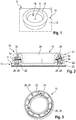
- FIG. 1 a capacitive motor vehicle operating system 10 is shown, which is used in an interior of a motor vehicle in order, for example, to control a multimedia system and / or vehicle functions of a motor vehicle.
- the capacitive motor vehicle operating system 10 comprises a capacitive screen 12, which has a user interface 14, so that a touch of the user interface 14 or an approach to the user interface 14 can be capacitively detected.
- the capacitive motor vehicle operating system 10 comprises a pressure and rotary actuation device 16, which is formed separately from the capacitive screen 12.
- the pressure and rotary actuation device 16 is essentially annular, the pressure and rotary actuation device 16 being arranged at least partially on the user interface 14 of the capacitive screen 12. This means that the pressure and rotary actuation device 16 occupies a partial area of the user interface 14.
- the pressure and rotary actuation device 16 is attached to the capacitive screen 12 in that the pressure and rotary actuation device 16 is glued, for example, to the capacitive screen 12, as will be explained below.
- the pressure and rotary actuation device 16 is arranged essentially stationary with respect to the capacitive screen 12. This means that the entire pressure and rotary actuation device 16 cannot be shifted on the capacitive screen 12, that is to say it can be moved laterally in the plane spanned by the capacitive screen 12, which corresponds to the user interface 14.
- the pressure and rotary actuation device 16 is designed to be electrically conductive in some areas, so that an electrical connection can be established via the pressure and rotary actuation device 16 to the capacitive screen 12 when an operator of the motor vehicle operating system 10 or a vehicle occupant of the capacitive motor vehicle operating system 10 via the pressure and Rotary actuating device 16 is actuated, that is to say it is approaching or touching it.
- the capacitive screen 12 which interacts with the electrically conductive pressure and rotary control device 16 in some areas, then detects the position and / or a change in position of the pressure and rotary control device 16, in particular a part of the pressure and rotary control device 16, with the capacitive screen 12 corresponding Signals generated in order to control an assigned function of the motor vehicle, as will be explained in detail below.
- the capacitive screen 12 includes a display area 18 on its user interface 14, which is assigned to the pressure and rotary actuation device 16, so that when the pressure and rotary actuation device 16 is actuated, optical feedback can be displayed on the capacitive screen 12, namely in the corresponding display area 18th
- the display area 18 can be provided within the ring-shaped pressure and rotary actuation device 16, as in the exemplary embodiment the Figure 1 is shown. In general, the display area 18 can also be provided at a different location on the capacitive screen 12.
- the pressure and rotary actuation device 16 is generally set up so that it can be rotated relative to the user interface 14 of the capacitive screen 12, that is to say in a plane parallel to the plane spanned by the capacitive screen 12.
- the axis of rotation A of the pressure and rotary actuation device 16 is stationary in relation to the capacitive screen 12.
- the pressure and rotary actuation device 16 can be actuated by means of a pressure actuation essentially perpendicular to the plane spanned by the capacitive screen 12, for example in the z direction, whereas the user interface 14 extends in the x and y directions.
- the user interface 14 of the capacitive screen 12 is contacted differently by the pressure and rotary actuation device 16 in an electrically conductive manner, whereby a correspondingly different contact pattern is detected and recognized by the capacitive screen 12, which is assigned to a correspondingly Function is implemented.
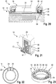
- FIG. 2 and 3 A capacitive motor vehicle operating system 10 according to a first embodiment is shown, wherein the pressure and rotary actuation device 16 is glued to a glass plate 20 of the capacitive screen 12.
- the pressure and rotary actuation device 16 comprises a stationary base 22, in particular a base ring, via which the pressure and rotary actuation device 16 is attached to the capacitive screen 12.
- the pressure and rotary actuation device 16 comprises an actuating element 24 which can be adjusted relative to the base 22, for example a rotating ring, via which the operator of the capacitive motor vehicle operating system 10 actuates the pressure and rotary actuation device 16.
- the pressure and rotary actuation device 16 comprises a plurality of magnets 28 embodied as interaction elements 26.
- a first group of magnets 28, which are assigned to the first level E1, is arranged in the rotatable actuating element 24 via a fixing ring 30 so that they can move with the rotatable actuating element 24 if this is actuated by the operator.
- a second group of magnets 28, which are assigned to the second level E2, are arranged in the area of the base 22, these magnets 28 being the interaction elements 26, since they interact with the capacitive screen 12.
- the interaction elements 26 or magnets 28 of the second group are movably arranged in an electrically conductive guide member 32, which can also be referred to as a guide ring, since the guide member 32 is ring-shaped and electrically conductive.
- the guide member 32 makes contact with at least the rotatable actuating element 24, so that an electrical connection can be established between the electrically conductive actuating element 24 and the guide member 32.
- the guide member 32 is rotated along with a rotary movement of the rotatable actuating element 24, that is to say is arranged non-rotatably in the actuating element 24.
- the pressure and rotary actuation device 16 has a stop 34, in particular a stop ring, which restricts the relative movement of the interaction elements 26 or magnets 28, i.e. the magnets 28 of the second group, in the z-direction, as will be explained below if the mode of operation of the motor vehicle operating system 10 according to the first embodiment is discussed.
- the magnet 28 assigned to the base 22, that is to say the interaction element 26, is pressed (electromagnetically) onto the user interface 14 of the capacitive screen 12, so that it contacts the user interface 14.
- the actuating element 24 or the rotating ring which is touched by the operator with his fingers, is electrically conductive, so that an electrical connection is established by the operator via the actuating element 24, the guide ring 32, the corresponding magnet 28 or the interaction element 26 to the capacitive screen 12 is. This is recognized by the capacitive screen 12.
- a rotation of the pressure and rotary actuation device 16 thus produces a relative change in position of the interaction elements 26, that is to say the magnets 28 in a plane perpendicular to the plane spanned by the capacitive screen 12, namely in the z-direction, since the user interface 14 is in the x and y directions.
- Direction is spanned.
- the other magnets 28 each with different poles face each other, whereby they attract each other.
- the relative attraction of the magnets 28 is limited by the stop 34.
- the pressure and rotary actuation device 16 is actuated by pressure, all interaction elements 26, i.e. the magnets 28, which are assigned to the base 22, are pressed simultaneously onto the user interface 14, since the actuation element 24 via the stop 34 acts on the corresponding interaction elements 26 or magnets 28 of the second group.
- the stop 34 or the stop ring can also be referred to as a pressure ring, since it ensures the pressure function of the pressure and rotary actuation device 16 by transmitting the pressure force to the interaction elements 26.
- the electrically conductive actuation element 24 that is to say the rotary ring, to touch the operating surface 14 with its periphery, which is accordingly detected by the capacitive screen 12.
- the pressure and rotary actuation device 16 includes haptic feedback, which is also generated via the magnets 28, in particular via the electromagnetic forces of the magnets 28, i.e. their mutual attraction or repulsion depending on the polarity of the opposing poles of the magnets 28 of both groups .
- the magnets 28 of the second group also have several functions at the same time, since they ensure the contact (interaction with the capacitive screen 12) as well as the haptic feedback.
- the interaction elements 26 have a stroke movement (in the z direction) of approximately 1 mm, that is to say both during the rotary actuation and the pressure actuation of the pressure and rotary actuation device 16.
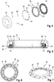
- a push and turn actuation device 16 of a capacitive motor vehicle operating system 10 according to a second embodiment is shown, which differs from the first embodiment in that the interaction elements 26 have been replaced by a single interaction element 26.
- the interaction element 26 is formed by an interaction ring 36 and comprises a plurality of sections 38 which can be actuated separately from one another, as will be explained below.
- the pressure and rotary actuation device 16 furthermore comprises a base 22 which is fastened directly to the capacitive screen 12, in particular is glued, which is not shown here for the sake of clarity.
- the pressure and rotary actuating device 16 further comprises an actuating element 24 which is adjustable or rotatable relative to the base 22 and which is electrically conductive.
- force transmission members 40 are provided in the second embodiment, each of which is spherical and interacts with the interaction element 26.
- the plurality of force transmission members 40 ensure that a movement that is as uniform as possible takes place during the rotary actuation of the pressure and rotary actuation device 16.
- At least one of the force transmission members 40 is electrically conductive, so that an electrical connection between the electrically conductive actuating element 24 and the electrically conductive interaction element 26 via the electrically conductive force transmission member 40 is ensured.
- the force transmission members 40 are rotatably coupled to the actuating element 24, which for this purpose, for example, on its internal geometry, form a receiving space for a force transmission member 40 in which the force transmission member 40 is received.
- the actuating element 24 when the actuating element 24 is actuated in a rotary manner, the force transmission members 40 are likewise rotated with the actuating element 24.
- the receiving space can be limited by stops and / or a corresponding contour can be formed on the internal geometry.
- the force transmission members 40 interact with the interaction ring 36, in particular the sections 38 of the interaction ring 36, since the force transmission members 40 move via the interaction ring 36.
- the corresponding section 38 is pressed by the corresponding force transmission member 40, viewed in the z direction, down onto the user interface 14.
- the multiple force transmission members 40 thus press the movable sections 38 of the interaction element 26 or interaction ring 36 onto the user interface 14, whereby an electrical connection from the operator via the electrically conductive actuation element 24, the electrically conductive force transmission member 40 and the corresponding one, at least in the case of the electrically conductive force transmission member 40 electrically conductive section 38 of the interaction element 26 to the user interface 14 is made.
- the sections 38 are each mechanically biased into a neutral position via a spring element 42, in which the sections 38 do not contact the user interface 14.
- the at least one interaction element 26 is mechanically preloaded.
- Tactile feedback from the pressure and rotary actuation device 16 is also provided about this, since the force transmission members 40 are pressed upward in the z-direction via the spring elements 42.
- the actuation element 24 presses all sections 38 simultaneously onto the user interface 14 via a projection 44 provided on the inside and the force transmission members 40.
- the projection 44 accordingly interacts with the interaction ring 36 or the interaction element 26.
- the user interface 14 is thus actuated with a corresponding contacting pattern, which is recognized by the capacitive screen 12 as a pressure actuation.
- the projection 44 is designed in particular in such a way that it has a stroke of 1 mm in the z-direction.
- the spring elements 42 ensure that the pressure and rotary actuation device 16 does not damage the capacitive screen 12 if too great a force should be exerted during a pressure actuation, since the spring elements 42 counteract this pressure force.
- twelve sections 38 and twelve associated spring elements 42 are shown in the embodiment shown, which can each be moved in the z direction, that is to say in a plane perpendicular to the plane spanned by the capacitive screen 12.
- FIG. 7 an alternative embodiment of the interaction ring 36 or the interaction element 26 is shown, which comprises a plurality of sections 38 which can be actuated individually and independently of one another.
- the interaction ring 36 is formed from a sheet metal that is segmented accordingly in order to provide the plurality of sections 38 which can be adjusted by the at least one force transmission member 40 relative to the user interface 14.
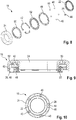
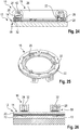
- a pressure and rotary actuation device 16 of a capacitive motor vehicle operating system 10 according to a third embodiment is shown, in which five force transmission members 40 are provided, of which one force transmission member 40 is electrically conductive.
- the electrically conductive force transmission element 40 is also assigned the electrically conductive interaction element 26 in the form of a receiving shoe 46, in which the force transmission element 40 designed as a ball is received.
- the pressure and rotary actuation device 16 comprises a base 22 which is fastened, in particular glued, to the capacitive screen 12. Furthermore, a to the base 22 adjustable or rotatable actuating element 24 is provided, which is electrically conductive and is actuated by the operator of the motor vehicle operating system 10.
- the force transmission members 40 which in turn are all designed as balls, are received in a cage 48 so that the position of the force transmission members 40 is fixed relative to one another.
- the force transmission members 40 are in turn assigned spring elements 42, via which the force transmission members 40 and thus also the at least one electrically conductive interaction element 26, that is to say the receiving shoe 46, are mechanically pretensioned.
- a toothed profile ring 50 is provided between the actuating element 24 and the spring elements 42, which ring has a toothed profile on the sides facing the spring elements 42. This can be used to provide haptic feedback when the pressure and rotary actuation device 16 is actuated.
- the spring elements 42 are also held on a spring retaining ring 52.
- the electrical connection is ensured via the electrically conductive actuating element 24, the at least one electrically conductive force transmission element 40 and the electrically conductive receiving shoe 46 or the electrically conductive interaction element 26.
- the receiving shoe 46 enlarges the contact surface on the user interface 14 accordingly.
- a pressure actuation of the pressure and rotary actuation device 16 takes place in that the actuation element 24 interacts over its entire circumference with the user interface 14, whereby a correspondingly clear signal is generated by the capacitive screen 12.
- the spring elements 42 are designed in such a way that they allow a stroke of approximately 1 mm in the z-direction when actuated by pressure until they lie flat on the spring retainer ring 52, that is, the spring path is used up.
- a fourth embodiment is shown in which five force transmission members 40 are provided in the form of balls in a manner analogous to the previous embodiment.
- the force transmission members 40 are designed to be flexible, however, so that they simultaneously provide haptic feedback, the pressure function and tolerance compensation.
- One of the force transmission members 40 is in turn designed to be electrically conductive, so that an electrical connection from the electrically conductive actuating element 24 via the electrically conductive force transmission member 40 to the user interface 14 of the capacitive screen 12 can be ensured.
- the rotary actuation results in a rotary movement of the force transmission members 40, a substantially annular rotary driver 54 transmitting the rotation of the actuating element 24 to the force transmission members 40 arranged in the cage 48.
- the cage 48 and the rotary driver 54 are formed separately from one another. Alternatively, however, these can also be coupled or even formed in one piece with one another.
- the rotary driver 54 is also designed to be electrically conductive, so that there is an electrical connection from the actuating element 24 via the rotary driver 54 to the electrically conductive force transmission element 40 or the electrically conductive interaction element 26.
- the base 22 each has recesses 56, through which at least the electrically conductive force transmission member 40 the user interface 14 can contact, so that the electrically conductive force transmission member 40 simultaneously represents the electrically conductive interaction element 26, which moves accordingly on a rotary actuation over the user interface 14 of the capacitive screen 12, which is detected by the capacitive screen 12.
- the entire actuation element 24 is pressed onto the user interface 14 of the capacitive screen 12, i.e. with its entire diameter, which is recognized by the capacitive screen 12 and converted into a corresponding pressure actuation function.
- a stroke of approximately 1 mm in the z-direction can be set via the elastic force transmission elements 40, which must be overcome when actuating the pressure.
- the elastic force transmission members 40 also set the pressure and rotary actuation device 16 back into its neutral position if there is no longer any pressure actuation.
- the base 22 can furthermore have a corresponding haptic feedback structure 55, via which tactile feedback is generated for the operator of the motor vehicle operating system 10 when he actuates the pressure and rotary actuation device 16. This is because the elastic force transmission members 40 compress due to the haptic feedback structure 55 of the base and then relax again.
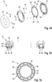
- FIG. 14 to 16 Another embodiment of the capacitive motor vehicle operating system 10 is shown, in which the at least one interaction element 26 is in turn formed by an interaction ring 36 which comprises a plurality of electrically conductive sections 38, which can each be actuated separately and independently of one another.
- the sections 38 each have a haptic feedback structure 55, which generate a tactile feedback when the pressure and rotary actuation device 16 is actuated by the operator, in particular when a rotary actuation is carried out in which the force transmission members 40 designed as balls are moved along the interaction element 26 , in particular sections 38.
- the interaction element 26 is received in the base 22, which is not electrically conductive.
- the base 22 also comprises recesses 56 through which the individual sections 38 extend.
- At least one force transmission member 40 is electrically conductive, which accordingly establishes an electrical connection between the electrically conductive actuating element 24 and the electrically conductive section 38 of the interaction element 26.
- the force transmission members 40 designed as balls or rolling bodies roll along the interaction element 26, in particular the interaction ring 36, with the sections 38 overrun by the force transmission members 40 on the capacitive screen 12 must be pressed.
- the electrically conductive force transmission element 40 then establishes the electrical connection with the correspondingly depressed section 38, which is detected by the capacitive screen 12.
- the separately actuatable sections 38 ensure that there is a relatively large actuation surface of the electrically conductive interaction element 26 on the capacitive screen 12, so that the actuation can easily be detected.
- the sections 38 include a haptic feedback structure 55, a haptic feedback results for the operator of the motor vehicle operating system 10 during the rotary actuation.
- the pressure and rotary actuation device 16 in turn comprises spring elements 42, via which the pressure actuation of the pressure and rotary actuation device 16 and the return of the pressure and rotary actuation device 16 to the neutral position are ensured.
- the spring elements 42 can be designed in such a way that a pressure actuation again results in a stroke of approximately 1 mm of the pressure and rotary actuation device 16 in the z-direction.
- the force transmission members 40 can be designed to be elastic, as a result of which damage to the capacitive screen 12 can be prevented if too great a pressure is exerted.
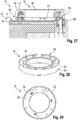
- FIG. 17 to 19 Another embodiment of a capacitive motor vehicle operating system 10 is shown, which comprises a rotary encoder 58.
- the rotary encoder 58 can generally detect the angle of rotation of the pressure and rotary actuation device 16 that occurs during a rotary actuation.
- the rotary encoder 58 has a capacitive design, since the pressure and rotary actuation device 16 has two detection areas 60, 62 which are separated from one another and are spaced apart from one another by a defined distance, such as in particular from FIG Figure 18 emerges.
- the detection areas 60, 62 are designed to be electrically conductive and accordingly form the electrically conductive interaction elements 26 which interact with the capacitive screen 12.
- the pressure and rotary actuation device 16 also has a plurality of force transmission members 40 which, when the pressure and rotary actuation device 16 is rotated, are adjusted by the adjustable actuating element 24 relative to the base 22, whereby they - depending on the angle of rotation - interact with the detection areas 60, 62 so that they establish an electrical connection to the user interface 14 via the corresponding detection area 60, 62.
- the force transmission members 40 are accordingly designed to be electrically conductive, whereby they are held in position relative to one another via a cage 48, that is to say seen in the circumferential direction.
- the cage 48 accordingly ensures that the force transmission members 40 each have the same distance from one another.
- the two detection areas 60, 62 or the two interaction elements 26 can determine at which angle and in which direction the Push and turn actuator 16 is rotated.
- the time resolution of the electrical connections of the two detection areas 60, 62 or the two interaction elements 26 is used.
- the angle of rotation can be determined accordingly via the number of actuations of the respective detection areas 60, 62.
- the pressure and rotary actuation device 16 formed separately from the capacitive screen 12 can generally also be fastened to the capacitive screen 12 via a mechanical connection such as a screw connection or the like, in particular in addition to a material connection, i.e. an adhesive bond.
- the rotary encoder 58 comprises an optical sensor 64, that is to say records the angle of rotation in an optical manner.
- the optical sensor 64 comprises at least one light transmitter and one light receiver.
- the rotary encoder 58 has a coding ring 66 which is assigned to the adjustable actuating element 24, for example, is coupled to the actuating element 24 in a rotationally fixed manner, so that the coding ring 66 is also rotated when the actuating element 24 is rotated.
- the coding ring 66 comprises a plurality of sections 68 which are separated from one another by recesses 70. A light beam emitted by the optical sensor 64 can pass through the recesses 70, which in turn is detected by the optical sensor 64.
- the light transmitter and the light receiver are assigned to opposite sides of the coding ring 66.
- the optical sensor 64 When the pressure and rotary actuation device 16 is actuated in a rotary manner, the optical sensor 64 accordingly detects the optical changes occurring due to the coding ring 66 in order to deduce the corresponding angle of rotation during the rotary actuation.
- the optical changes are caused by the fact that the light from the transmitter of the optical sensor 64 passes through one of the recesses 70 and can be received by the receiver of the optical sensor 64 or is blocked by one of the sections 68.
- the optical sensor 64 works with two light beams, for example with two light transmitters and two light receivers, the direction of rotation can also be used can be recognized when the pressure and rotary actuation device 16 is rotated.
- the optical sensor 64 is assigned to the glass plate 20 of the capacitive screen 12, in particular partially accommodated in the glass plate 20.
- the glass plate 20 is at least partially drilled through.
- the pressure actuation of the pressure and rotary actuation device 16 takes place in a known manner in that spring elements 42 are pressed together until the electrically conductive actuation element 24 comes into contact with the capacitive screen 12, in particular the user interface 14, which is accordingly detected by the capacitive screen 12.
- the actuation element 24 represents the interaction element 26, which interacts with the capacitive screen 12.
- the spring elements 42 provide the haptic feedback and also ensure that the actuating element 24 returns to its neutral position.
- the rotary encoder 58 comprises at least one Hall sensor 72 which interacts with magnets 28 which are assigned to the actuating element 24.
- the magnets 28 can be arranged in a guide member 32, which can also be referred to as a guide ring.
- the guide member 32 can in turn be coupled in a rotationally fixed manner to the actuation element 24, so that the magnets 28 move over the user interface 14 when actuated in a rotary manner, and thus also over the Hall sensors 72.
- the magnets 28 When the push-and-turn actuator 16 is rotated, the magnets 28 cause a change in magnetic flux, which is detected by the Hall sensor 72.
- magnets 28 are assigned to user interface 14, in particular with alternating polarity.
- the Hall sensors 72 can be arranged below the glass plate 20 of the capacitive screen 12, for example below the capacitive sensor layer of the capacitive screen 12.
- the magnets 28 can represent the interaction elements 26, as was previously based on FIG Figures 2 and 3 has already been explained.
- the actuation element 24 can represent the interaction element 26, provided that a pressure actuation is exerted, as has already been described above.
- the spring elements 42 can in turn serve for haptic feedback and provide a stroke in the z-direction of approximately 1 mm.
- the rotary encoder 58 comprises at least one inductive coil 74, which is formed, for example, via an FPC cable.
- the FPC cable is also arranged below the glass plate 20 of the capacitive screen 12, with a change in inductance being detected by the at least one inductive coil 74 in order to detect a rotation of the push-and-turn actuator 16.
- an induction material 76 such as a piece of iron is assigned to the actuating element 24, which is correspondingly detected by the at least one inductive coil 74 when the actuating element 24 is rotated, that is to say is subjected to a rotary actuation.
- the pressure actuation can again take place against the spring force of the spring elements 42, so that the actuation element 24 serves as the interaction element 26, since the electrically conductive actuation element 24 interacts with the capacitive screen 12.
Landscapes
- Engineering & Computer Science (AREA)
- General Engineering & Computer Science (AREA)
- Theoretical Computer Science (AREA)
- General Physics & Mathematics (AREA)
- Physics & Mathematics (AREA)
- Human Computer Interaction (AREA)
- Mechanical Engineering (AREA)
- Chemical & Material Sciences (AREA)
- Transportation (AREA)
- Combustion & Propulsion (AREA)
- Mechanical Control Devices (AREA)
- Switches With Compound Operations (AREA)
- Position Input By Displaying (AREA)
- User Interface Of Digital Computer (AREA)
Description
- Die Erfindung betrifft ein kapazitives Kraftfahrzeugbediensystem für den Innenraum eines Kraftfahrzeugs.
- Aus dem Stand der Technik sind Kraftfahrzeugbediensysteme bekannt, mit denen Funktionen eines Kraftfahrzeugs ein- bzw. ausgeschaltet werden können, beispielsweise ein Multimediasystem eines Kraftfahrzeugs. Die Kraftfahrzeugbediensysteme umfassen üblicherweise durch mechanische Schalter und Ähnliches ausgebildete Bedienelemente, die von einem Fahrzeuginsassen gedrückt bzw. gedreht werden, um eine zugeordnete Funktion zu aktivieren bzw. zu deaktivieren.
- Bei modernen Kraftfahrzeugen sind darüber hinaus kapazitive Kraftfahrzeugbediensysteme mit entsprechend kapazitiven Bedienelementen bekannt, die eine Annäherung bzw. ein Berühren erfassen, woraufhin das Kraftfahrzeugbediensystem eine zugeordnete Funktion ausführt. Die aus dem Stand der Technik bekannten kapazitiven Kraftfahrzeugbediensysteme sind jedoch verhältnismäßig komplex aufgebaut, wodurch die Herstellungskosten entsprechend hoch sind.
- Darüber hinaus sind kapazitive Bildschirme zur Steuerung von Fahrzeugfunktionen bekannt, auf denen entsprechende Schaltsymbole bzw. Schaltflächen angezeigt werden, die ein Fahrzeuginsasse berühren bzw. denen er sich annähern kann, um eine zugeordnete Funktion auszuführen. Neben üblichen Schaltflächen sind auch sogenannte Gleitbereiche bekannt, entlang derer der Bediener des Kraftfahrzeugbediensystems beispielsweise seinen Finger gleiten lassen kann, um eine Funktion stufenlos oder stufenweise einzustellen. Bei der entsprechenden Funktion kann es sich um eine Lautstärkeregelung eines Multimediasystems handeln, bei der der Bediener des Kraftfahrzeugbediensystems seinen Finger entlang eines auf der kapazitiven Bedienoberfläche des kapazitiven Bildschirms dargestellten Bereichs bewegt, um die gewünschte Lautstärke einzustellen.
- Als nachteilig hat sich bei den kapazitiven Bildschirmen herausgestellt, dass die zur Bedienung benötigten Flächen auf dem kapazitiven Bildschirm entsprechend groß sind, wodurch sich nur wenige Funktionen gleichzeitig auf dem kapazitiven Bildschirm abbilden lassen.
- Die
FR 3 056 475 A1 FR 3 056 474 A1 FR 3 058 938 A1 - In der
FR 3 035 981 A1 - Die
DE 10 2015 002 300 A1 zeigt eine Eingabevorrichtung, die lateral verschiebbar an einer Halterung angebracht ist, wobei die Halterung an einer in Form eines Touchscreens ausgebildeten Eingabeeinrichtung befestigt ist. - Die Aufgabe der Erfindung ist es, ein einfach aufgebautes und leicht zu bedienendes Kraftfahrzeugbediensystem zur Verfügung zu stellen.
- Die Aufgabe wird erfindungsgemäß gelöst durch ein kapazitives Kraftfahrzeugbediensystem, umfassend einen kapazitiven Bildschirm mit einer Bedienoberfläche sowie eine zum kapazitiven Bildschirm separat ausgebildete Druck- und Drehbetätigungsvorrichtung, die bereichsweise elektrisch leitfähig ist und zumindest teilweise auf der Bedienoberfläche des kapazitiven Bildschirms so befestigt ist, wobei die Druck- und Drehbetätigungsvorrichtung zumindest ein elektrisch leitfähiges Interaktionselement umfasst, das mit dem kapazitiven Bildschirm interagiert. Dabei erfolgt eine Druckbetätigung im Wesentlichen parallel zu einer Drehachse in Richtung des kapazitiven Bildschirms. Zudem liegt bei der Betätigung der Druck- und Drehbetätigungsvorrichtung eine elektrische Verbindung zwischen der Bedienoberfläche des kapazitiven Bildschirms und einem drehbaren Betätigungselement der Druck- und Drehbetätigungsvorrichtung vor. Die elektrische Verbindung ist über das zumindest eine elektrisch leitfähige Interaktionselement bereitgestellt, das die Bedienoberfläche bei der Betätigung kontaktiert. Die Druck- und Drehbetätigungsvorrichtung ist ringförmig ausgebildet. Das Kraftfahrzeugbediensystem ist ausgebildet, zumindest eine Druckbetätigung der Druck- und Drehbetätigungsvorrichtung mittels des kapazitiven Bildschirms in kapazitiver Weise zu erfassen. Die gesamte Druck- und Drehbetätigungsvorrichtung ist in einer vom Bildschirm aufgespannten Ebene lateral unbeweglich.
- Der Grundgedanke der Erfindung ist es, dass eine elektrische Verbindung zwischen dem Bediener des Kraftfahrzeugbediensystems und dem kapazitiven Bildschirm, insbesondere der Bedienoberfläche, hergestellt wird, wenn der Bediener die zumindest bereichsweise elektrisch leitfähige Druck- und Drehbetätigungsvorrichtung berührt bzw. sich dieser annähert, wodurch eine elektrische Verbindung zwischen dem Bediener und dem kapazitiven Bildschirm über die hierzu separat ausgebildete Druck- und Drehbetätigungsvorrichtung hergestellt ist.
- Da die Druck- und Drehbetätigungsvorrichtung auf der Bedienoberfläche des kapazitiven Bildschirms zumindest teilweise befestigt ist, ist es nicht möglich, dass die gesamte Druck- und Drehbetätigungsvorrichtung über den kapazitiven Bildschirm, insbesondere dessen Bedienoberfläche, bewegt wird, um eine entsprechende Funktion auf dem Bildschirm auszuführen. Erfindungsgemäß ist vielmehr vorgesehen, dass eine feste Zuordnung zwischen der Druck- und Drehbetätigungsvorrichtung sowie dem darunter angeordneten kapazitiven Bildschirm vorliegt, wodurch entsprechende Funktionen platzsparend aktiviert bzw. deaktiviert werden können. Mit anderen Worten ist die Druck- und Drehbetätigungsvorrichtung ortsfest auf dem kapazitiven Bildschirm angeordnet, da sie stets und unabhängig von der Aktion dieselbe Fläche auf dem kapazitiven Bildschirm einnimmt.
- Beispielsweise lässt sich über die Drehbetätigung der Druck- und Drehbetätigungsvorrichtung eine Lautstärkenregelung vornehmen bzw. wird so durch ein Adressbuch gescrollt.
- Die Druck- und Drehbetätigungsvorrichtung kann in einfacher Weise auf dem kapazitiven Bildschirm aufgeklebt sein, wodurch diese entsprechend ortsfest an dem kapazitiven Bildschirm befestigt ist.
- Der kapazitive Bildschirm ist in gewohnter Weise eingerichtet, sodass er die Position und/oder die Bewegung des wenigstens einen elektrisch leitfähigen Interaktionselements der Druck- und Drehbetätigungsvorrichtung in Bezug auf den kapazitiven Bildschirm erfasst, sofern ein Kontakt zum kapazitiven Bildschirm vorliegt, und entsprechende Signale ausgibt, die in entsprechende Funktionen umgesetzt werden, beispielsweise von einer übergeordneten Steuer- und/oder Recheneinheit.
- Generell können für die Druckbetätigung und die Drehbetätigung der Druck- und Drehbetätigungsvorrichtung separat ausgebildete Interaktionselemente vorgesehen sein, also zumindest ein Druckbetätigungs-Interaktionselement sowie zumindest ein Drehbetätigungs- Interaktionselement.
- Insbesondere stellt die Druck- und Drehbetätigungsvorrichtung bei Betätigung eine haptische Rückmeldung bereit.
- Zudem ist die gesamte Druck- und Drehbetätigungsvorrichtung in einer vom Bildschirm aufgespannten Ebene lateral unbeweglich.
- Die Druck- und Drehbetätigungsvorrichtung kann eine ortsfeste Basis aufweisen, insbesondere in Bezug auf den kapazitiven Bildschirm. Die Druck- und Drehbetätigungsvorrichtung ist beispielsweise über die ortsfeste Basis auf dem kapazitiven Bildschirm befestigt, insbesondere derart dass die gesamte Druck- und Drehbetätigungsvorrichtung in einer vom Bildschirm aufgespannten Ebene lateral unbeweglich ist.
- Um die Drehbetätigung der Druck- und Drehbetätigungsvorrichtung sicherzustellen, kann die Druck- und Drehbetätigungsvorrichtung ein, insbesondere ringförmig ausgebildetes, Betätigungselement aufweisen, das verstellbar ist. Eine Verdrehung des verstellbaren Betätigungselements in Bezug auf die Basis ist demnach möglich, um die Drehbetätigung zu realisieren.
- Ferner lässt sich die Druck- und Drehbetätigungsvorrichtung um eine Drehachse drehen, die im Wesentlichen senkrecht zur Oberfläche des kapazitiven Bildschirms ist.
- Die Druckbetätigung erfolgt demnach im Wesentlichen parallel zur Drehachse, also in Richtung des kapazitiven Bildschirms.
- Über die elektrische Verbindung erkennt der kapazitive Bildschirm, dass die Druck- und Drehbetätigungsvorrichtung vom Bediener des Kraftfahrzeugbediensystems bedient wird. Die hergestellte elektrische Verbindung kann als ein Trigger-Signal bzw. Auslösesignal für das Kraftfahrzeugbediensystem angesehen werden. Die elektrische Verbindung wird über das zumindest eine elektrisch leitfähige Interaktionselement bereitgestellt, das die Bedienoberfläche bei Betätigung kontaktiert.
- Sofern der Bediener eine Drehbetätigung der Druck- und Drehbetätigungsvorrichtung vornimmt, kann das elektrisch leitfähige Interaktionselement über die Bedienoberfläche bewegt werden, wobei der kapazitive Bildschirm die Bewegung entsprechend erkennt.
- Der kapazitive Bildschirm kann ferner eingerichtet sein, die Fläche, also die Größe der Fläche, und/oder verschiedene Positionen auf der Bedienoberfläche zu erfassen, die vom Interaktionselement bei einer Betätigung der Druck- und Drehbetätigungsvorrichtung kontaktiert wird bzw. werden, um hierüber auf eine entsprechende Bedienung der Druck- und Drehbetätigungsvorrichtung zu schließen.
- Beispielsweise führt eine Druckbetätigung der Druck- und Drehbetätigungsvorrichtung dazu, dass ein großer Flächenkontakt zwischen dem Interaktionselement und der Bedienoberfläche vorliegt, was von dem kapazitiven Bildschirm als Druckbetätigung erkannt wird, sodass eine mit der Druckbetätigung verknüpfte Funktion ausgeführt wird.
- Insofern ist ein einfach aufgebautes Kraftfahrzeugbediensystem geschaffen, das eine entsprechende Druckbetätigung kapazitiv erfasst, wozu die Druck- und Drehbetätigungsvorrichtung bereichsweise elektrisch leitfähig ist, um mit dem kapazitiven Bildschirm zu interagieren. Eine Berührung des kapazitiven Bildschirms durch den Bediener ist somit nicht notwendig.
- Gemäß einer Ausführungsform sind mehrere Interaktionselemente vorgesehen, über die der Drehwinkel der Druck- und Drehbetätigungsvorrichtung erfassbar ist. Alternativ oder ergänzend umfasst das wenigstens eine Interaktionselement mehrere Abschnitte, die separat voneinander betätigbar sind und über die der Drehwinkel der Druck- und Drehbetätigungsvorrichtung erfassbar ist, insbesondere wobei die mehreren Abschnitte jeweils eine haptische Rückmeldungsstruktur umfassen. Die mehreren Interaktionselemente sind über die der Druck- und Drehbetätigungsvorrichtung zugeordneten Fläche auf dem kapazitiven Bildschirm verteilt angeordnet. In Abhängigkeit von der Betätigung der Druck- und Drehbetätigungsvorrichtung ergibt sich somit ein unterschiedlicher Kontakt auf dem kapazitiven Bildschirm durch die mehreren Interaktionselemente. Beispielsweise kontaktiert nur eines der mehreren Interaktionselemente den kapazitiven Bildschirm, sodass über die Position des entsprechenden Interaktionselements auf dem kapazitiven Bildschirm auf die Drehbetätigung geschlossen werden kann, insbesondere den Drehwinkel. Hierbei kann die zeitliche Abfolge der jeweiligen Kontaktierungen des kapazitiven Bildschirms durch die mehreren Interaktionselemente berücksichtigt werden.
- Alternativ oder ergänzend können elektrisch leitfähige Abschnitte eines (einstückig ausgebildeten) Interaktionselements vorgesehen sein, beispielsweise eines Blechs mit entsprechenden Segmenten bzw. Abschnitten, die in Abhängigkeit von der Betätigung der Druck- und Drehbetätigungsvorrichtung relativ zum kapazitiven Bildschirm verstellt werden, um diesen zu kontaktieren. Hierdurch ist dann eine elektrische Verbindung mit dem kapazitiven Bildschirm hergestellt, was entsprechend vom kapazitiven Bildschirm detektiert wird.
- Ferner können die Abschnitte des (einteilig ausgebildeten Interaktionselements) jeweils eine haptische Rückmeldungsstruktur umfassen, die eine entsprechende taktile Rückmeldung an den Bediener bereitstellt, wenn die Druck- und Drehbetätigungsvorrichtung gedreht wird.
- Des Weiteren kann die Druck- und Drehbetätigungsvorrichtung zumindest ein Kraftübertragungsglied aufweisen, das mit dem Interaktionselement zusammenwirkt. Bei dem Kraftübertragungsglied kann es sich um ein rollbares Kraftübertragungsglied handeln, beispielsweise einer Kugel, welches bei einer Drehbetätigung der Druck- und Drehbetätigungsvorrichtung relativ zur Bedienoberfläche bewegt werden kann.
- Dabei kann das Kraftübertragungsglied relativ zu dem zumindest einen Interaktionselement bewegt werden, wobei es das zumindest eine Interaktionselement in einer zur Bedienoberfläche des kapazitiven Bildschirms senkrechten Richtung verstellt, wenn es über das zumindest eine Interaktionselement aufgrund der Drehbetätigung der Druck- und Drehbetätigungsvorrichtung bewegt wird. Insbesondere wird das Kraftübertragungsglied über das (einstückig ausgebildete) Interaktionselement bei einer Drehbetätigung der Druck- und Drehbetätigungsvorrichtung verfahren, wodurch es die entsprechend einzeln und separat voneinander betätigbaren Abschnitte relativ zum kapazitiven Bildschirm verstellt.
- Es können auch mehrere Kraftübertragungsglieder vorgesehen sein, um eine homogene bzw. gleichmäßige Drehbetätigung der Druck- und Drehbetätigungsvorrichtung zu gewährleisten. Die mehreren Kraftübertragungsglieder sind dabei vorzugsweise im Wesentlichen gleich beabstandet zueinander.
- Auch kann das Kraftübertragungsglied gleichzeitig das Interaktionselement sein, sofern das Kraftübertragungsglied elektrisch leitfähig ist. Bei dem Kraftübertragungsglied kann es sich um eine elektrisch leitfähige (und optional elastische) Kugel handeln.
- Generell kann das Kraftübertragungsglied elektrisch leitfähig sein, sofern über das Kraftübertragungsglied die elektrische Verbindung vom drehbaren Betätigungselement zur Bedienoberfläche des kapazitiven Bildschirms ausgebildet wird.
- Es kann das zumindest eine Interaktionselement, bei Betätigung der Druck- und Drehbetätigungsvorrichtung, eine zur Bedienoberfläche des kapazitiven Bildschirms relative Positionsveränderung erfahren. Die Betätigung der Druck- und Drehbetätigungsvorrichtung stellt somit sicher, dass das zumindest eine Interaktionselement relativ zur Bedienoberfläche des kapazitiven Bildschirms verstellt wird, was von dem kapazitiven Bildschirm entsprechend erfasst wird. Sofern das zumindest eine Interaktionselement über den kapazitiven Bildschirm bewegt wird, erfolgt über die Drehbewegung des Interaktionselements eine relative Positionsveränderung.
- Beispielsweise erfolgt die relative Positionsveränderung in einer zur Bedienoberfläche des kapazitiven Bildschirms senkrechten Ebene. Dies ist insbesondere bei einer Druckbetätigung der Druck- und Drehbetätigungsvorrichtung der Fall. Darüber hinaus kann auch bei einer Drehbetätigung der Druck- und Drehbetätigungsvorrichtung eine zur Bedienoberfläche senkrechte relative Positionsveränderung des zumindest einen Interaktionselements auftreten. Dies ist insbesondere dann möglich, wenn mehrere (in Draufsicht und in Bezug auf den Bildschirm ortsfeste) Interaktionselemente vorgesehen sind, die unterschiedlichen Regionen des kapazitiven Bildschirms zugeordnet sind, wodurch eine orts- und/oder zeitaufgelöste Erfassung der Kontaktierung der mehreren Interaktionselemente erfolgt. Die mehreren Interaktionselemente können unabhängig voneinander durch das zumindest eine Kraftübertragungsglied senkrecht zu der vom kapazitiven Bildschirm aufgespannten Ebene verstellt werden, wenn das Kraftübertragungsglied mit dem entsprechenden Interaktionselement interagiert.
- Ein weiterer Aspekt sieht vor, dass das wenigstens eine Interaktionselement durch zumindest einen Magneten ausgebildet ist. Über den Magneten kann die elektrische Verbindung in einfacher Weise entsprechend hergestellt werden. Ferner kann das Interaktionselement dann elektromagnetisch verstellt werden. Beispielsweise sind mehrere Magnete vorgesehen, die miteinander elektromagnetisch interagieren. Die mehreren Magnete können in zwei Ebenen angeordnet sein, wobei die Magnete beider Ebenen miteinander wechselwirken. Die eine Ebene der Magnete kann bei einer Drehbetätigung der Druck- und Drehbetätigungsvorrichtung relativ zur anderen Ebene der Magnete verdreht werden, sodass sich unterschiedliche Pole der Magnete gegenüberliegen, was zu einer abstoßenden elektromagnetischen Kraft führt, wodurch eine elektrische Kontaktierung des kapazitiven Bildschirms erfolgt.
- Beispielsweise ist das wenigstens eine Interaktionselement elastisch, mechanisch vorgespannt und/oder elektromagnetisch vorgespannt. Hierdurch ist es möglich, dass sich die Druck- und Drehbetätigungsvorrichtung in eine Neutralstellung zurückstellt, wenn vom Bediener keine Kraft mehr ausgeübt wird, also nachdem die Druck- und Drehbetätigungsvorrichtung betätigt worden ist. Darüber hinaus kann über die Vorspannung eine haptische Rückmeldung für den Bediener des Kraftfahrzeugbediensystems erzeugt werden. Des Weiteren lässt sich über die Vorspannung sicherstellen, dass das zumindest eine Interaktionselement in der gewünschten Position verbleibt. Sofern das Interaktionselement elastisch ist, weist das Interaktionselement somit eine inhärente Vorspannung auf.
- Ferner kann die Vorspannung eine Sicherheitsfunktion bereitstellen, da der kapazitive Bildschirm bei Betätigung der Druck- und Drehbetätigungsvorrichtung nicht beschädigt wird.
- Auch kann vorgesehen sein, dass das wenigstens eine Interaktionselement durch eine elektrisch leitfähige Kugel ausgebildet ist, die beispielsweise zusätzlich elastisch ist. Bei einer Drehbetätigung der Druck- und Drehbetätigungsvorrichtung erzeugt die elektrisch leitfähige Kugel eine entsprechende elektrische Verbindung auf dem kapazitiven Bildschirm, wodurch die Betätigung der Druck- und Drehbetätigungsvorrichtung vom kapazitiven Bildschirm erfasst wird. Aufgrund der Elastizität ist ferner sichergestellt, dass eine taktile Rückmeldung erfolgt, die auch als haptische Rückmeldung bezeichnet wird.
- Allgemein kann die Druck- und Drehbetätigungsvorrichtung wenigstens zwei elektrisch leitfähige Abschnitte umfassen, die als Interaktionselemente dienen und an unterschiedlichen Positionen in Bezug auf den kapazitiven Bildschirm vorgesehen sind. Die elektrisch leitfähigen Abschnitte können mit wenigstens einem (elektrisch leitfähigen) Kraftübertragungsglied zusammenwirken. Bei einer Drehbetätigung der Druck- und Drehbetätigungsvorrichtung werden die beiden elektrisch leitfähigen Abschnitte somit zu unterschiedlichen Zeitpunkten (über das zumindest eine Kraftübertragungsglied) betätigt, wodurch sich die Bewegungsrichtung der Druck- und Drehbetätigungsvorrichtung bei einer Drehbetätigung feststellen lässt.
- Des Weiteren kann das Kraftfahrzeugbediensystem einen Drehgeber umfassen, über den der Drehwinkel der Druck- und Drehbetätigungsvorrichtung bei einer Drehbetätigung erfassbar ist. Der Drehgeber, auch Encoder genannt, kann auf unterschiedliche Weise ausgebildet sein.
- Beispielsweise umfasst der Drehgeber einen optischen Sensor, einen Hall-Sensor und/oder eine induktive Spule. Dementsprechend lässt sich der Drehgeber neben der kapazitiven Weise auch in optischer und/oder elektromagnetischer Weise bereitstellen.
- Das zumindest eine elektrisch leitfähige Interaktionselement kann demnach ausschließlich zur Druckbetätigung der Druck- und Drehbetätigungsvorrichtung dienen, da die Drehbetätigung der Druck- und Drehbetätigungsvorrichtung durch den Drehgeber erfasst wird, insbesondere in optischer und/oder elektromagnetischer Weise.
- Ferner kann der kapazitive Bildschirm zumindest einen Anzeigebereich aufweisen, der der Druck- und Drehbetätigungsvorrichtung zugeordnet ist und, bei Betätigung der Druck- und Drehbetätigungsvorrichtung, eine optische Rückmeldung ausgibt. Demnach ist das kapazitive Kraftfahrzeugbediensystem gleichzeitig dazu ausgebildet, eine optische (sowie taktile) Rückmeldung bereitzustellen, sodass der Bediener des kapazitiven Kraftfahrzeugbediensystems sofort eine entsprechende Rückmeldung erhält.
- Insbesondere umfasst die Druck- und Drehbetätigungsvorrichtung eine ortsfeste Basis und ein zur Basis verstellbares Betätigungselement. Die ortsfeste Basis ist dabei auf dem kapazitiven Bildschirm befestigt, insbesondere auf dem kapazitiven Bildschirm aufgeklebt. Das verstellbare Betätigungselement wird bei einer Dreh- bzw. Druckbetätigung relativ zur ortsfesten Basis bewegt. Bei einer Drehbetätigung ergibt sich demnach eine Verdrehung des verstellbaren Betätigungselements in Bezug auf die Basis. Das verstellbare Betätigungselement ist insbesondere elektrisch leitfähig ausgebildet.
- Generell kann die Druck- und Drehbetätigungsvorrichtung ein elektrisch leitfähiges Interaktionselement umfassen, das für die Druckbetätigung der Druck- und Drehbetätigungsvorrichtung vorgesehen ist.
- Zudem kann die Druck- und Drehbetätigungsvorrichtung ein elektrisch leitfähiges Interaktionselement umfassen, das für die Drehbetätigung der Druck- und Drehbetätigungsvorrichtung vorgesehen ist. Das elektrisch leitfähige Interaktionselement kann sich dabei über die Bedienoberfläche bewegen oder in einer hierzu senkrechten Richtung, insbesondere dann, wenn das elektrisch leitfähige Interaktionselement mit einem Kraftübertragungsglied zusammenwirkt.
- Alternativ oder ergänzend kann vorgesehen sein, dass die Drehbetätigung der Druck- und Drehbetätigungsvorrichtung über einen Drehgeber bzw. einen Encoder erfasst wird, beispielsweise in kapazitiver, optischer und/oder elektromagnetischer Weise, also aufgrund von Induktion und/oder aufgrund des Hall-Effekts.
- Das wenigstens eine Kraftübertragungsglied dient insbesondere dazu, eine Drehkraft in eine laterale Kraft zu übertragen bzw. zu übersetzen, indem das Kraftübertragungsglied beispielsweise mit dem elektrisch leitfähigen Interaktionselement zusammenwirkt und dieses verstellt.
- Generell handelt es sich bei dem kapazitiven Bildschirm um ein Anzeigefeld, auf dem Inhalte dargestellt werden können, insbesondere aufgrund von elektrischen Ansteuerungssignalen. Der kapazitive Bildschirm ist zudem berührungs- bzw. annäherungssensitiv ausgebildet.
- Weitere Vorteile und Eigenschaften ergeben sich aus der nachfolgenden Beschreibung und den Zeichnungen, auf die Bezug genommen wird. In den Zeichnungen zeigen:
-
Figur 1 eine perspektivische Ansicht eines erfindungsgemäßen kapazitiven Kraftfahrzeugbediensystems, -
Figur 2 eine Schnittansicht durch ein kapazitives Kraftfahrzeugbediensystem gemäß einer ersten Ausführungsform, -
Figur 3 eine Ansicht auf die Unterseite der Druck- und Drehbetätigungsvorrichtung des Kraftfahrzeugbediensystems nachFigur 2 , -
Figur 4 eine Explosionsansicht einer Druck- und Drehbetätigungsvorrichtung eines erfindungsgemäßen kapazitiven Kraftfahrzeugbediensystems gemäß einer zweiten Ausführungsform, -
Figur 5 eine Schnittansicht der Druck- und Drehbetätigungsvorrichtung nachFigur 4 , -
Figur 6 eine Ansicht auf die Unterseite der Druck- und Drehbetätigungsvorrichtung nachFigur 4 , -
Figur 7 eine perspektivische Ansicht eines Interaktionselements einer Druck- und Drehbetätigungsvorrichtung eines erfindungsgemäßen kapazitiven Kraftfahrzeugbediensystems, -
Figur 8 eine Explosionsansicht einer Druck- und Drehbetätigungsvorrichtung eines erfindungsgemäßen kapazitiven Kraftfahrzeugbediensystems gemäß einer dritten Ausführungsform, -
Figur 9 eine Schnittansicht der Druck- und Drehbetätigungsvorrichtung nachFigur 8 , -
Figur 10 eine Ansicht von unten auf die Druck- und Drehbetätigungsvorrichtung nachFigur 8 , -
Figur 11 eine Explosionsansicht einer Druck- und Drehbetätigungsvorrichtung eines erfindungsgemäßen kapazitiven Kraftfahrzeugbediensystems gemäß einer vierten Ausführungsform, -
Figur 12 eine Schnittansicht der Druck- und Drehbetätigungsvorrichtung nachFigur 11 , -
Figur 13 eine Ansicht von unten auf die Druck- und Drehbetätigungsvorrichtung nachFigur 11 , -
Figur 14 eine Explosionsansicht einer Druck- und Drehbetätigungsvorrichtung eines erfindungsgemäßen kapazitiven Kraftfahrzeugbediensystems gemäß einer fünften Ausführungsform, -
Figur 15 eine Schnittansicht der Druck- und Drehbetätigungsvorrichtung der nachFigur 14 , -
Figur 16 eine Ansicht von unten auf die Druck- und Drehbetätigungsvorrichtung nachFigur 14 , -
Figur 17 eine Schnittansicht eines erfindungsgemäßen kapazitiven Kraftfahrzeugbediensystems gemäß einer sechsten Ausführungsform, -
Figur 18 eine Ansicht von unten auf die Druck- und Drehbetätigungsvorrichtung des Kraftfahrzeugbediensystems nachFigur 17 , -
Figur 19 eine Ansicht auf die Basis des Kraftfahrzeugbediensystems nachFigur 17 , -
Figur 20 eine Schnittansicht eines erfindungsgemäßen kapazitiven Kraftfahrzeugbediensystems gemäß einer siebten Ausführungsform, -
Figur 21 eine Detailansicht derFigur 20 , -
Figur 22 eine Ansicht von unten auf die Druck- und Drehbetätigungsvorrichtung des Kraftfahrzeugbediensystems nachFigur 20 , -
Figur 23 eine perspektivische Darstellung eines Teils der Druck- und Drehbetätigungsvorrichtung des Kraftfahrzeugbediensystems nachFigur 20 , -
Figur 24 eine Schnittansicht eines erfindungsgemäßen kapazitiven Kraftfahrzeugbediensystems gemäß einer achten Ausführungsform, -
Figur 25 eine teiltransparente Darstellung der Druck- und Drehbetätigungsvorrichtung des Kraftfahrzeugbediensystems nachFigur 24 , -
Figur 26 eine Schnittdarstellung des Kraftfahrzeugbediensystems ausFigur 24 , -
Figur 27 eine Schnittdarstellung eines erfindungsgemäßen kapazitiven Kraftfahrzeugbediensystems gemäß einer neunten Ausführungsform, -
Figur 28 eine Teildarstellung der Druck- und Drehbetätigungsvorrichtung des Kraftfahrzeugbediensystems nachFigur 27 , und -
Figur 29 eine Ansicht von unten auf die Druck- und Drehbetätigungsvorrichtung des Kraftfahrzeugbediensystems nachFigur 27 . - In
Figur 1 ist ein kapazitives Kraftfahrzeugbediensystem 10 gezeigt, die in einem Innenraum eines Kraftfahrzeugs zum Einsatz kommt, um beispielsweise ein Multimediasystem und/oder Fahrzeugfunktionen eines Kraftfahrzeugs zu steuern. - Das kapazitive Kraftfahrzeugbediensystem 10 umfasst einen kapazitiven Bildschirm 12, der eine Bedienoberfläche 14 hat, sodass eine Berührung der Bedienoberfläche 14 oder eine Annäherung an die Bedienoberfläche 14 kapazitiv erfasst werden kann.
- Des Weiteren umfasst das kapazitive Kraftfahrzeugbediensystem 10 eine Druck- und Drehbetätigungsvorrichtung 16, die separat zum kapazitiven Bildschirm 12 ausgebildet ist.
- In der gezeigten Ausführungsform ist die Druck- und Drehbetätigungsvorrichtung 16 im Wesentlichen ringförmig ausgebildet, wobei die Druck- und Drehbetätigungsvorrichtung 16 zumindest teilweise auf der Bedienoberfläche 14 des kapazitiven Bildschirms 12 angeordnet ist. Dies bedeutet, dass die Druck- und Drehbetätigungsvorrichtung 16 eine Teilfläche der Bedienoberfläche 14 belegt.
- Die Druck- und Drehbetätigungsvorrichtung 16 ist dabei auf dem kapazitiven Bildschirm 12 befestigt, indem die Druck- und Drehbetätigungsvorrichtung 16 beispielsweise mit dem kapazitiven Bildschirm 12 verklebt ist, wie nachfolgend noch erläutert wird.
- Insofern ist sichergestellt, dass die Druck- und Drehbetätigungsvorrichtung 16 im Wesentlichen ortsfest in Bezug auf den kapazitiven Bildschirm 12 angeordnet ist. Dies bedeutet, dass die gesamte Druck- und Drehbetätigungsvorrichtung 16 nicht auf dem kapazitiven Bildschirm 12 verschoben werden kann, also lateral in der vom kapazitiven Bildschirm 12 aufgespannten Ebene bewegt werden kann, die der Bedienoberfläche 14 entspricht.
- Die Druck- und Drehbetätigungsvorrichtung 16 ist bereichsweise elektrisch leitfähig ausgebildet, sodass eine elektrische Verbindung über die Druck- und Drehbetätigungsvorrichtung 16 zum kapazitiven Bildschirm 12 hergestellt werden kann, wenn ein Bediener des Kraftfahrzeugbediensystems 10 bzw. ein Fahrzeuginsasse das kapazitive Kraftfahrzeugbediensystem 10 über die Druck- und Drehbetätigungsvorrichtung 16 betätigt, also sich dieser annähert bzw. diese berührt.
- Der kapazitive Bildschirm 12, der mit der bereichsweise elektrisch leitfähigen Druck- und Drehbetätigungsvorrichtung 16 zusammenwirkt, erkennt dann die Position und/oder eine Positionsveränderung der Druck- und Drehbetätigungsvorrichtung 16, insbesondere eines Teils der Druck- und Drehbetätigungsvorrichtung 16, wobei der kapazitive Bildschirm 12 entsprechende Signale erzeugt, um eine zugeordnete Funktion des Kraftfahrzeugs anzusteuern, wie nachfolgend noch detailliert erläutert wird.
- Beispielsweise umfasst der kapazitive Bildschirm 12 an seiner Bedienoberfläche 14 einen Anzeigebereich 18, der der Druck- und Drehbetätigungsvorrichtung 16 zugeordnet ist, sodass bei Betätigung der Druck- und Drehbetätigungsvorrichtung 16 eine optische Rückmeldung auf dem kapazitiven Bildschirm 12 angezeigt werden kann, nämlich in dem entsprechenden Anzeigebereich 18.
- Der Anzeigebereich 18 kann innerhalb der ringförmigen Druck- und Drehbetätigungsvorrichtung 16 vorgesehen sein, wie dies im Ausführungsbeispiel der
Figur 1 gezeigt ist. Generell kann der Anzeigebereich 18 auch an einer anderen Stell auf dem kapazitiven Bildschirm 12 vorgesehen sein. - Die Druck- und Drehbetätigungsvorrichtung 16 ist generell eingerichtet, dass sie relativ zur Bedienoberfläche 14 des kapazitiven Bildschirms 12 gedreht werden kann, also in einer zur vom kapazitiven Bildschirm 12 aufgespannten Ebene parallelen Ebene. Die Drehachse A der Druck- und Drehbetätigungsvorrichtung 16 ist dabei ortsfest in Bezug auf den kapazitiven Bildschirm 12.
- Des Weiteren lässt sich die Druck- und Drehbetätigungsvorrichtung 16 mittels einer Druckbetätigung im Wesentlichen senkrecht zu der vom kapazitiven Bildschirm 12 aufgespannten Ebene betätigen, beispielsweise in z-Richtung, wohingegen die Bedienoberfläche 14 sich in x- und y-Richtung erstreckt.
- Je nach Betätigung der Druck- und Drehbetätigungsvorrichtung 16 wird die Bedienoberfläche 14 des kapazitiven Bildschirms 12 anders von der Druck- und Drehbetätigungsvorrichtung 16 in elektrisch leitender Weise kontaktiert, wodurch ein entsprechend unterschiedliches Kontaktmuster vom kapazitiven Bildschirm 12 erfasst und erkannt wird, das in eine entsprechend zugeordnete Funktion umgesetzt wird.
- In den
Figuren 2 und 3 ist eine kapazitive Kraftfahrzeugbediensystem 10 gemäß einer ersten Ausführungsform gezeigt, wobei die Druck- und Drehbetätigungsvorrichtung 16 auf einer Glasplatte 20 des kapazitiven Bildschirms 12 geklebt ist. - Aus der
Figur 2 geht hervor, dass die Druck- und Drehbetätigungsvorrichtung 16 eine ortsfeste Basis 22 umfasst, insbesondere einen Basisring, über den die Druck- und Drehbetätigungsvorrichtung 16 auf dem kapazitiven Bildschirm 12 befestigt ist. - Ferner umfasst die Druck- und Drehbetätigungsvorrichtung 16 ein zur Basis 22 verstellbares Betätigungselement 24, beispielsweise einen Drehring, über das der Bediener des kapazitiven Kraftfahrzeugbediensystems 10 die Druck- und Drehbetätigungsvorrichtung 16 betätigt.
- Darüber hinaus umfasst die Druck- und Drehbetätigungsvorrichtung 16 in der gezeigten Ausführungsform mehrere als Interaktionselemente 26 ausgebildete Magnete 28.
- Generell sind mehrere Magnete 28 vorgesehen, die in zwei unterschiedlichen Ebenen E1, E2 angeordnet sind.
- Eine erste Gruppe der Magnete 28, die der ersten Ebene E1 zugeordnet sind, ist über einen Fixierring 30 im drehbaren Betätigungselement 24 angeordnet, sodass sie sich mit dem drehbaren Betätigungselement 24 bewegen können, sofern dieses vom Bediener betätigt wird.
- Eine zweite Gruppe der Magnete 28, die der zweiten Ebene E2 zugeordnet sind, sind im Bereich der Basis 22 angeordnet, wobei es sich bei diesen Magneten 28 um die Interaktionselemente 26 handelt, da sie mit dem kapazitiven Bildschirm 12 interagieren.
- Die Interaktionselemente 26 bzw. Magnete 28 der zweiten Gruppe sind beweglich in einem elektrisch leitfähigen Führungsglied 32 angeordnet, das auch als Leitring bezeichnet werden kann, da das Führungsglied 32 ringförmig und elektrisch leitfähig ist.
- Das Führungsglied 32 kontaktiert zumindest das drehbare Betätigungselement 24, sodass eine elektrische Verbindung zwischen dem elektrisch leitfähigen Betätigungselement 24 und dem Führungsglied 32 ausgebildet werden kann.
- Es kann auch vorgesehen sein, dass das Führungsglied 32 bei einer Drehbewegung des drehbaren Betätigungselements 24 mitgedreht wird, also drehfest im Betätigungselement 24 angeordnet ist.
- Darüber hinaus geht aus der
Figur 2 hervor, dass die Druck- und Drehbetätigungsvorrichtung 16 einen Anschlag 34 aufweist, insbesondere einen Anschlagring, der die relative Bewegung der Interaktionselemente 26 bzw. Magnete 28, also der Magnete 28 der zweiten Gruppe, in z-Richtung beschränkt, wie nachfolgend erläutert wird, wenn auf die Funktionsweise der Kraftfahrzeugbediensystem 10 gemäß der ersten Ausführungsform eingegangen wird. - In der in
Figur 2 gezeigten Stellung ist das Betätigungselement 24 bzw. der Drehring derart zur Basis 22 verdreht worden, dass die beiden Magnete 28 auf der in der Schnittdarstellung links gezeigten Seite mit ihren gleichartigen Polen zueinander weisen, wodurch sie sich voneinander abstoßen. - Dadurch wird der der Basis 22 zugeordnete Magnet 28, also das Interaktionselement 26, auf die Bedienoberfläche 14 des kapazitiven Bildschirms 12 (elektromagnetisch) gedrückt, sodass dieser die Bedienoberfläche 14 kontaktiert. Das Betätigungselement 24 bzw. der Drehring, der vom Bediener mit seinen Fingern berührt wird, ist elektrisch leitfähig, sodass eine elektrische Verbindung vom Bediener über das Betätigungselement 24, den Leitring 32, den entsprechenden Magneten 28 bzw. das Interaktionselement 26 zum kapazitiven Bildschirm 12 hergestellt ist. Dies wird vom kapazitiven Bildschirm 12 erkannt.
- Eine Drehung der Druck- und Drehbetätigungsvorrichtung 16 erzeugt somit eine relative Positionsveränderung der Interaktionselemente 26, also der Magnete 28 in einer zur von dem kapazitiven Bildschirm 12 aufgespannten Ebene senkrechten Ebene, nämlich in z-Richtung, da die Bedienoberfläche 14 in x- und y-Richtung aufgespannt ist.
- Wie auf deren rechten Seite der
Figur 2 gezeigt ist, weisen die anderen Magnete 28 mit jeweils unterschiedlichen Polen aufeinander zu, wodurch sie sich gegenseitig anziehen. Die relative Anziehung der Magnete 28 wird dabei durch den Anschlag 34 begrenzt. - Aus der
Figur 3 , die eine Ansicht von unten auf die Druck- und Drehbetätigungsvorrichtung 16 zeigt, geht hervor, dass die der Basis 22 zugeordneten Magnete 28 jeweils im Wesentlichen homogen über die Basis 22 verteilt sind, also äquidistant in Umfangsrichtung. - Bei einer Drehbetätigung der Druck- und Drehbetätigungsvorrichtung 16 können mehrere Magnete 28 bzw. Interaktionselemente 26 die Bedienoberfläche 14 berühren, wodurch ein entsprechendes Betätigungsmuster auf dem kapazitiven Bildschirm 12 erzeugt wird, was vom kapazitiven Bildschirm 12 in ein entsprechendes Signal umgewandelt wird. Insbesondere wandern die Kontaktstellen der Interaktionselemente 26 auf der Bedienoberfläche 14 während einer Drehbetätigung, was vom kapazitiven Bildschirm 12 entsprechend erfasst wird.
- Sofern die Druck- und Drehbetätigungsvorrichtung 16 gemäß der Kraftfahrzeugbediensystem 10 der ersten Ausführungsform eine Druckbetätigung erfährt, werden sämtliche Interaktionselemente 26, also die Magnete 28, die der Basis 22 zugeordnet sind, gleichzeitig auf die Bedienoberfläche 14 gedrückt, da das Betätigungselement 24 über den Anschlag 34 auf die entsprechenden Interaktionselemente 26 bzw. Magnete 28 der zweiten Gruppe wirkt. Insofern kann das Anschlag 34 bzw. der Anschlagring auch als Druckring bezeichnet werden, da über ihn die Druckfunktion der Druck- und Drehbetätigungsvorrichtung 16 sichergestellt ist, indem es die Druckkraft auf die Interaktionselemente 26 überträgt.
- Sofern der Bediener die Druck- und Drehbetätigungsvorrichtung 16 nicht mehr drückt, wird diese aufgrund der magnetischen Vorspannung in ihre Neutralstellung zurückversetzt, die in
Figur 2 gezeigt ist. - Bei der Druckbetätigung kann auch vorgesehen sein, dass das elektrisch leitfähige Betätigungselement 24, also der Drehring, mit seinem Umfang die Bedienoberfläche 14 berührt, was vom kapazitiven Bildschirm 12 entsprechend detektiert wird.
- Darüber hinaus umfasst die Druck- und Drehbetätigungsvorrichtung 16 eine haptische Rückmeldung, die ebenfalls über die Magnete 28 erzeugt wird, insbesondere über die elektromagnetischen Kräfte der Magnete 28, also deren gegenseitige Anziehung bzw. Abstoßung je nach Polarität der sich gegenüberliegenden Pole der Magnete 28 beider Gruppen.
- Insofern ergibt sich eine haptische Rückmeldung für den Bediener, die keinem Temperatureinfluss unterliegt. Auch weisen die Magnete 28 der zweiten Gruppe mehrere Funktionen gleichzeitig auf, da sie die Kontaktierung (Interaktion mit dem kapazitiven Bildschirm 12) als auch die haptische Rückmeldung sicherstellen.
- Generell kann vorgesehen sein, dass die Interaktionselemente 26 eine Hubbewegung (in z-Richtung) von etwa 1 mm aufweisen, also sowohl bei der Drehbetätigung als auch der Druckbetätigung der Druck- und Drehbetätigungsvorrichtung 16.
- In den
Figuren 4 bis 6 ist eine Druck- und Drehbetätigungsvorrichtung 16 eines kapazitiven Kraftfahrzeugbediensystems 10 gemäß einer zweiten Ausführungsform gezeigt, das sich von der ersten Ausführungsform dahingehend unterscheidet, dass die Interaktionselemente 26 durch ein einziges Interaktionselement 26 ersetzt worden ist. - Das Interaktionselement 26 ist durch einen Interaktionsring 36 ausgebildet und umfasst mehrere Abschnitte 38, die separat voneinander betätigbar sind, wie nachfolgend erläutert wird.
- Aus der Explosionsansicht geht hervor, dass die Druck- und Drehbetätigungsvorrichtung 16 weiterhin eine Basis 22 umfasst, die direkt auf dem kapazitiven Bildschirm 12 befestigt wird, insbesondere geklebt wird, der aus Gründen der besseren Übersicht hier nicht gezeigt ist.
- Darüber hinaus umfasst die Druck- und Drehbetätigungsvorrichtung 16 weiterhin ein zur Basis 22 verstellbares bzw. hierzu drehbares Betätigungselement 24, das elektrisch leitfähig ist.
- Zudem sind in der zweiten Ausführungsform Kraftübertragungsglieder 40 vorgesehen, die jeweils kugelförmig ausgebildet sind und mit dem Interaktionselement 26 zusammenwirken.
- Die mehreren Kraftübertragungsglieder 40 stellen sicher, dass eine möglichst gleichmäßige Bewegung bei der Drehbetätigung der Druck- und Drehbetätigungsvorrichtung 16 erfolgt.
- Zumindest eines der Kraftübertragungsglieder 40 ist dabei elektrisch leitfähig, sodass eine elektrische Verbindung zwischen dem elektrisch leitfähigen Betätigungselement 24 und dem elektrisch leitfähigen Interaktionselement 26 über das elektrische leitfähige Kraftübertragungsglied 40 sichergestellt ist.
- Die Kraftübertragungsglieder 40 sind drehfest mit dem Betätigungselement 24 gekoppelt, das hierzu beispielsweise an seiner Innengeometrie einen Aufnahmeraum für ein Kraftübertragungsglied 40 ausbilden, in dem das Kraftübertragungsglied 40 aufgenommen ist. Insofern werden bei einer Drehbetätigung des Betätigungselements 24 die Kraftübertragungsglieder 40 ebenfalls mit dem Betätigungselement 24 mitgedreht.
- Der Aufnahmeraum kann durch Anschläge begrenzt und/oder eine entsprechende Kontur an der Innengeometrie ausgebildet sein.
- Bei der Drehbetätigung der Druck- und Drehbetätigungsvorrichtung 16 bzw. des Betätigungselements 24 interagieren die Kraftübertragungsglieder 40 mit dem Interaktionsring 36, insbesondere den Abschnitten 38 des Interaktionsrings 36, da sich die Kraftübertragungsglieder 40 über den Interaktionsring 36 bewegen.
- Sobald eines der Kraftübertragungsglieder 40 über einen Abschnitt 38 des Interaktionsrings 36 bewegt wird, wird der entsprechende Abschnitt 38 vom entsprechenden Kraftübertragungsglied 40, in z-Richtung gesehen, nach unten auf die Bedienoberfläche 14 gedrückt. Die mehreren Kraftübertragungsglieder 40 drücken also die bewegbaren Abschnitte 38 des Interaktionselements 26 bzw. Interaktionsrings 36 auf die Bedienoberfläche 14, wodurch zumindest bei dem elektrisch leitfähigen Kraftübertragungsglied 40 eine elektrische Verbindung vom Bediener über das elektrisch leitfähige Betätigungselement 24, das elektrisch leitfähige Kraftübertragungsglied 40 sowie den entsprechenden elektrisch leitfähigen Abschnitt 38 des Interaktionselements 26 zur Bedienoberfläche 14 hergestellt ist.
- Darüber hinaus sind die Abschnitte 38 jeweils über eine Federelement 42 mechanisch in eine Neutralstellung vorgespannt, in der die Abschnitte 38 nicht die Bedienoberfläche 14 kontaktieren. Insofern ist das wenigstens eine Interaktionselement 26 mechanisch vorgespannt.
- Hierüber wird ebenfalls eine taktile Rückmeldung der Druck- und Drehbetätigungsvorrichtung 16 bereitgestellt, da die Kraftübertragungsglieder 40 über die Federelemente 42 in z-Richtung nach oben gedrückt werden.
- Sofern die Druck- und Drehbetätigungsvorrichtung 16 einer Druckbetätigung unterliegt, drückt das Betätigungselement 24 über einen innenseitig vorgesehenen Vorsprung 44 sowie die Kraftübertragungsglieder 40 sämtliche Abschnitte 38 gleichzeitig auf die Bedienoberfläche 14. Der Vorsprung 44 wirkt demnach mit dem Interaktionsring 36 bzw. dem Interaktionselement 26 zusammen.
- Die Bedienoberfläche 14 wird so mit einem entsprechenden Kontaktierungsmuster betätigt, was vom kapazitiven Bildschirm 12 als Druckbetätigung erkannt wird.
- Der Vorsprung 44 ist insbesondere derart ausgebildet, dass er einen Hubweg von 1 mm in z-Richtung aufweist.
- Darüber hinaus stellen die Federelemente 42 sicher, dass die Druck- und Drehbetätigungsvorrichtung 16 den kapazitiven Bildschirm 12 nicht beschädigt, sofern eine zu große Kraft bei einer Druckbetätigung ausgeübt werden sollte, da die Federelemente 42 dieser Druckkraft entgegenwirken.
- Grundsätzlich sind in der gezeigten Ausführungsform zwölf Abschnitte 38 sowie zwölf zugeordnete Federelemente 42 gezeigt, die jeweils in z-Richtung bewegt werden können, also in einer zu der vom kapazitiven Bildschirm 12 aufgespannten Ebene senkrechten Ebene.
- In
Figur 7 ist eine alternative Ausführung des Interaktionsrings 36 bzw. des Interaktionselements 26 gezeigt, das mehrere Abschnitte 38 umfasst, die einzeln und unabhängig voneinander betätigbar sind. - Der Interaktionsring 36 ist aus einem Blech gebildet, der entsprechend segmentiert ist, um die mehreren Abschnitte 38 bereitzustellen, die von dem zumindest einem Kraftübertragungsglied 40 relativ zur Bedienoberfläche 14 verstellt werden können.
- Die Betätigung des in
Figur 7 gezeigten Interaktionsrings 36 bzw. Interaktionselements 26 erfolgt im Wesentlichen in analoger Weise zur Betätigung des in denFiguren 4 bis 6 gezeigten Interaktionsrings 36 bzw. Interaktionselements 26. - In den
Figuren 8 bis 10 ist eine Druck- und Drehbetätigungsvorrichtung 16 eines kapazitiven Kraftfahrzeugbediensystems 10 gemäß einer dritten Ausführungsform gezeigt, bei der fünf Kraftübertragungsglieder 40 vorgesehen sind, von denen ein Kraftübertragungsglied 40 elektrisch leitfähig ist. - Dem elektrisch leitfähigen Kraftübertragungsglied 40 ist zudem das elektrisch leitfähige Interaktionselement 26 in Form eines Aufnahmeschuhs 46 zugeordnet, in dem das als Kugel ausgebildete Kraftübertragungsglied 40 aufgenommen ist.
- In analoger Weise zur vorherigen Ausführungsform umfasst die Druck- und Drehbetätigungsvorrichtung 16 eine Basis 22, die auf dem kapazitiven Bildschirm 12 befestigt ist, insbesondere aufgeklebt ist. Ferner ist ein zur Basis 22 verstellbares bzw. drehbares Betätigungselement 24 vorgesehen, das elektrisch leitfähig ist und vom Bediener des Kraftfahrzeugbediensystems 10 betätigt wird.
- Die Kraftübertragungsglieder 40, die wiederum allesamt als Kugeln ausgebildet sind, sind in einen Käfig 48 aufgenommen, sodass die Position der Kraftübertragungsglieder 40 relativ zueinander fix ist.
- Den Kraftübertragungsgliedern 40 sind wiederum Federelemente 42 zugeordnet, über die die Kraftübertragungsglieder 40 und somit auch das wenigstens eine elektrisch leitfähige Interaktionselement 26, also der Aufnahmeschuh 46, mechanisch vorgespannt sind.
- Zudem ist zwischen dem Betätigungselement 24 und den Federelementen 42 ein Zahnprofilring 50 vorgesehen, der ein Zahnprofil auf der zu den Federelementen 42 gerichteten Seiten aufweist. Hierüber lässt sich eine haptische Rückmeldung beim Betätigen der Druck- und Drehbetätigungsvorrichtung 16 bereitstellen.
- Die Federelemente 42 sind zudem an einem Federhaltering 52 gehalten.
- Bei einer Drehbetätigung der Druck- und Drehbetätigungsvorrichtung 16 wird die Drehbewegung des verstellbaren Betätigungselements 24 auf den Käfig 48 und somit auf die Kraftübertragungsglieder 40 übertragen, wobei der Aufnahmeschuh 46 bzw. das Interaktionselement 26 über die Bedienoberfläche 14 bewegt wird.
- Die elektrische Verbindung wird dabei über das elektrisch leitfähige Betätigungselement 24, das wenigstens eine elektrisch leitfähige Kraftübertragungsglied 40 sowie den elektrisch leitfähigen Aufnahmeschuh 46 bzw. das elektrisch leitfähige Interaktionselement 26 sichergestellt.
- Der Aufnahmeschuh 46 vergrößert die Auflagefläche auf der Bedienoberfläche 14 entsprechend.
- Eine Druckbetätigung der Druck- und Drehbetätigungsvorrichtung 16 erfolgt dadurch, dass das Betätigungselement 24 über seinen gesamten Umfang mit der Bedienoberfläche 14 zusammenwirkt, wodurch ein entsprechend eindeutiges Signal vom kapazitiven Bildschirm 12 erzeugt wird.
- Die Federelemente 42 sind dabei derart ausgebildet, dass sie einen Hubweg von ungefähr 1 mm in z-Richtung bei einer Druckbetätigung ermöglichen, bis sie flächig auf dem Federhaltering 52 aufliegen, also der Federweg aufgebraucht ist.
- Sobald die Druckbetätigung nicht mehr vorliegt, drücken die Federelemente 42 das Betätigungselement 24 in seine Neutralstellung zurück.
- In den
Figuren 11 bis 13 ist eine vierte Ausführungsform gezeigt, bei der in analoger Weise zur vorherigen Ausführungsform fünf Kraftübertragungsglieder 40 in Form von Kugeln vorgesehen sind. - Die Kraftübertragungsglieder 40 sind jedoch flexibel ausgebildet, sodass sie gleichzeitig eine haptische Rückmeldung, die Druckfunktion und eine Toleranzkompensation bereitstellen.
- Eines der Kraftübertragungsglieder 40 ist wiederum elektrisch leitfähig ausgebildet, sodass eine elektrische Verbindung vom elektrisch leitfähigen Betätigungselement 24 über das elektrisch leitfähige Kraftübertragungsglied 40 zur Bedienoberfläche 14 des kapazitiven Bildschirms 12 sichergestellt werden kann.
- Bei einer Drehbetätigung der Druck- und Drehbetätigungsvorrichtung 16 rotieren die Kraftübertragungsglieder 40 über die Basis 22, wobei wiederum ein Käfig 48 vorgesehen ist, der die Kraftübertragungsglieder 40 in ihren Positionen hält.
- Die Drehbetätigung hat eine Drehbewegung der Kraftübertragungsglieder 40 zur Folge, wobei ein im Wesentlichen ringförmiger Drehmitnehmer 54 die Drehung des Betätigungselements 24 auf die im Käfig 48 angeordneten Kraftübertragungsglieder 40 überträgt. In der gezeigten Ausführungsform sind der Käfig 48 und der Drehmitnehmer 54 separat voneinander ausgebildet. Alternativ können diese jedoch auch gekoppelt oder sogar einstückig miteinander ausgebildet sein.
- Der Drehmitnehmer 54 ist ebenfalls elektrisch leitfähig ausgebildet, sodass eine elektrische Verbindung vom Betätigungselement 24 über den Drehmitnehmer 54 zum elektrisch leitfähigen Kraftübertragungsglied 40 bzw. dem elektrisch leitfähiges Interaktionselement 26 vorliegt.
- Die Basis 22 weist jeweils Ausnehmungen 56 auf, durch die zumindest das elektrisch leitfähige Kraftübertragungsglied 40 die Bedienoberfläche 14 kontaktieren kann, sodass das elektrisch leitfähige Kraftübertragungsglied 40 gleichzeitig das elektrisch leitfähige Interaktionselement 26 darstellt, das sich bei einer Drehbetätigung über die Bedienoberfläche 14 des kapazitiven Bildschirms 12 entsprechend bewegt, was vom kapazitiven Bildschirm 12 erfasst wird.
- Bei einer Druckbetätigung der Druck- und Drehbetätigungsvorrichtung 16 wird das gesamte Betätigungselement 24 auf die Bedienoberfläche 14 des kapazitiven Bildschirms 12 gedrückt, also mit seinem gesamten Durchmesser, was vom kapazitiven Bildschirm 12 erkannt und in eine entsprechende Druckbetätigungsfunktion umgesetzt wird.
- In dieser Ausführungsform sind keine separaten Federelemente bzw. Vorspannungselemente vorgesehen, da die Kraftübertagungsglieder 40 aufgrund ihrer Elastizität eine inhärente mechanische Vorspannung aufweisen.
- Über die elastischen Kraftübertagungsglieder 40 lässt sich ein Hubweg von etwa 1 mm in z-Richtung einstellen, der bei einer Druckbetätigung überwunden werden muss.
- Die elastischen Kraftübertagungsglieder 40 stellen zudem die Druck- und Drehbetätigungsvorrichtung 16 in ihre Neutralstellung zurück, sofern keine Druckbetätigung mehr vorliegt.
- Die Basis 22 kann ferner einer entsprechende haptische Rückmeldungsstruktur 55 aufweisen, über die eine taktile Rückmeldung für den Bediener des Kraftfahrzeugbediensystems 10 erzeugt wird, wenn er die Druck- und Drehbetätigungsvorrichtung 16 betätigt. Dies liegt daran, dass die elastischen Kraftübertagungsglieder 40 aufgrund der haptischen Rückmeldungsstruktur 55 der Basis komprimieren und sich dann wieder entspannen.
- In den
Figuren 14 bis 16 ist eine weitere Ausführungsform des kapazitiven Kraftfahrzeugbediensystems 10 gezeigt, bei dem das zumindest eine Interaktionselement 26 wiederum durch einen Interaktionsring 36 ausgebildet ist, der mehrere elektrisch leitfähige Abschnitte 38 umfasst, die jeweils separat und unabhängig voneinander betätigbar sind. - Die Abschnitte 38 weisen jeweils eine haptische Rückmeldungsstruktur 55 auf, die eine taktile Rückmeldung erzeugen, wenn die Druck- und Drehbetätigungsvorrichtung 16 vom Bediener betätigt wird, insbesondere wenn eine Drehbetätigung ausgeführt wird, bei der die als Kugeln ausgebildeten Kraftübertragungsglieder 40 entlang des Interaktionselements 26 bewegt werden, insbesondere den Abschnitten 38.
- Aus den
Figuren 15 und 16 geht hervor, dass das Interaktionselement 26 in der Basis 22 aufgenommen ist, die nicht elektrisch leitfähig ist. Die Basis 22 umfasst hierzu ebenfalls Ausnehmungen 56, durch die sich die einzelnen Abschnitte 38 erstrecken. - Von den mehreren Kraftübertragungsgliedern 40 ist zumindest ein Kraftübertragungsglied 40 elektrisch leitfähig, das entsprechend eine elektrische Verbindung zwischen dem elektrisch leitfähigen Betätigungselement 24 und dem elektrisch leitfähigen Abschnitt 38 des Interaktionselements 26 herstellt.
- Bei der Betätigung der Druck- und Drehbetätigungsvorrichtung 16 wird demnach, wie bereits zuvor erläutert, eine elektrische Verbindung vom Bediener über das elektrisch leitfähige Betätigungselement 24 sowie das elektrisch leitfähige Kraftübertragungsglied 40 und dem zugeordneten elektrisch leitfähigen Abschnitt 38 des Interaktionselements 26 zum kapazitiven Bildschirm 12 hergestellt, da das Kraftübertragungsglied 40 den Abschnitt 38, in z-Richtung gesehen, nach unten drückt.
- Wie bei den vorherigen Ausführungsformen bereits erläutert, rollen die als Kugeln bzw. Rollkörper ausgebildeten Kraftübertragungsglieder 40 bei einer Drehbetätigung der Druck- und Drehbetätigungsvorrichtung 16 entlang des Interaktionselements 26, insbesondere des Interaktionsrings 36, wobei die von den Kraftübertragungsgliedern 40 überrollten Abschnitte 38 auf den kapazitiven Bildschirm 12 gedrückt werden. Das elektrisch leitfähige Kraftübertragungsglied 40 stellt dann mit dem entsprechend heruntergedrückten Abschnitt 38 die elektrische Verbindung her, was vom kapazitiven Bildschirm 12 erfasst wird.
- Über die separat betätigbaren Abschnitte 38 ist sichergestellt, dass eine verhältnismäßig große Betätigungsfläche des elektrisch leitfähigen Interaktionselements 26 auf dem kapazitiven Bildschirm 12 vorliegt, sodass die Betätigung leicht erfasst werden kann.
- Um die Kraftübertragungsglieder 40 relativ zueinander in Position zu halten sind diese wiederum in einem Käfig 48 aufgenommen, der entsprechend drehfest mit dem Betätigungselement 24 gekoppelt ist.
- Da die Abschnitte 38 eine haptische Rückmeldungsstruktur 55 umfassen, ergibt sich für den Bediener der Kraftfahrzeugbediensystem 10 bei der Drehbetätigung eine haptische Rückmeldung.
- Des Weiteren umfasst die Druck- und Drehbetätigungsvorrichtung 16 wiederum Federelemente 42, über die die Druckbetätigung der Druck- und Drehbetätigungsvorrichtung 16 sowie die Rückstellung der Druck- und Drehbetätigungsvorrichtung 16 in die Neutralstellung sichergestellt ist.
- Die Federelemente 42 können dabei so ausgebildet sein, dass sich bei einer Druckbetätigung wiederum ein Hubweg von ungefähr 1 mm der Druck- und Drehbetätigungsvorrichtung 16 in z-Richtung ergibt.
- Bei einer Druckbetätigung der Druck- und Drehbetätigungsvorrichtung 16 wird das gesamte Betätigungselement 24, also der Drehring, auf die kapazitive Bedienoberfläche 14 des kapazitiven Bildschirms 12 gedrückt, sodass sein Außenumfang flächig aufliegt.
- Hierdurch wird vom kapazitiven Bildschirm 12 ein entsprechendes Signal erzeugt.
- Generell können die Kraftübertragungsglieder 40 elastisch ausgebildet sein, wodurch eine Beschädigung des kapazitiven Bildschirms 12 verhindert werden kann, wenn eine zu große Druckbetätigung ausgeübt wird.
- In den
Figuren 17 bis 19 ist eine weitere Ausführungsform eines kapazitiven Kraftfahrzeugbediensystems 10 gezeigt, das einen Drehgeber 58 umfasst. - Der Drehgeber 58 kann generell den bei einer Drehbetätigung auftretenden Drehwinkel der Druck- und Drehbetätigungsvorrichtung 16 erfassen.
- In der gezeigten Ausführungsform ist der Drehgeber 58 kapazitiv ausgebildet, da die Druck- und Drehbetätigungsvorrichtung 16 zwei voneinander separierte Detektionsbereiche 60, 62 aufweist, die voneinander um einen definierten Abstand beabstandet sind, wie insbesondere aus
Figur 18 hervorgeht. - Die Detektionsbereiche 60, 62 sind elektrisch leitfähig ausgebildet und bilden demnach die elektrisch leitfähigen Interaktionselemente 26 aus, die mit dem kapazitiven Bildschirm 12 interagieren.
- Die Druck- und Drehbetätigungsvorrichtung 16 weist ebenfalls mehrere Kraftübertragungsglieder 40 auf, die bei einer Drehbetätigung der Druck- und Drehbetätigungsvorrichtung 16 vom verstellbaren Betätigungselement 24 relativ zur Basis 22 verstellt werden, wobei sie - je nach Drehwinkel - mit den Detektionsbereichen 60, 62 interagieren, sodass sie eine elektrische Verbindung zur Bedienoberfläche 14 über den entsprechenden Detektionsbereich 60, 62 herstellen.
- Die Kraftübertragungsglieder 40 sind demnach elektrisch leitfähig ausgebildet, wobei sie über einen Käfig 48 relativ zueinander in Position gehalten werden, also in Umfangsrichtung gesehen. Der Käfig 48 stellt demnach sicher, dass die Kraftübertragungsglieder 40 jeweils einen gleichen Abstand zueinander aufweisen.
- Aufgrund des Abstands der Kraftübertragungsglieder 40 zueinander sowie des Abstands der Detektionsbereiche 60, 62 zueinander kann bei einer Drehbetätigung der Druck- und Drehbetätigungsvorrichtung 16 über die beiden Detektionsbereiche 60, 62 bzw. die beiden Interaktionselemente 26 festgestellt werden, um welchen Winkel und in welche Richtung die Druck- und Drehbetätigungsvorrichtung 16 gedreht wird.
- Hierzu wird auf die Zeitauflösung der elektrischen Verbindungen der beiden Detektionsbereiche 60, 62 bzw. der beiden Interaktionselemente 26 abgestellt.
- Über die Anzahl der Betätigung der jeweiligen Detektionsbereiche 60, 62 lässt sich der Drehwinkel entsprechend ermitteln.
- Bei einer Druckbetätigung der Druck- und Drehbetätigungsvorrichtung 16 wird wiederum das gesamte Betätigungselement 24 über seinen (Außen-)Durchmesser auf die Bedienoberfläche 14 gedrückt, was entsprechend vom kapazitiven Bildschirm 12 erfasst wird.
- Wie unter anderem aus der
Figur 17 hervorgeht, kann die zum kapazitiven Bildschirm 12 separat ausgebildete Druck- und Drehbetätigungsvorrichtung 16 generell auch über eine mechanische Verbindung wie einer Schraubverbindung oder ähnlichem an dem kapazitiven Bildschirm 12 befestigt sein, insbesondere zusätzlich zu einer stoffschlüssigen Verbindung, also einer Klebung. - In den
Figuren 20 bis 22 ist eine weitere Ausführungsform gezeigt, bei der der Drehgeber 58 einen optischen Sensor 64 umfasst, also den Drehwinkel in optischer Weise erfasst. Der optische Sensor 64 umfasst wenigstens einen Lichtsender sowie einen Lichtempfänger. - Zudem weist der Drehgeber 58 einen Codierring 66 auf, der dem verstellbaren Betätigungselement 24 zugeordnet ist, beispielsweise mit dem Betätigungselement 24 drehfest gekoppelt ist, sodass der Codierring 66 mitgedreht wird, wenn das Betätigungselement 24 gedreht wird.
- Der Codierring 66 umfasst mehrere Abschnitte 68, die durch Ausnehmungen 70 voneinander getrennt sind. Durch die Ausnehmungen 70 kann ein vom optischen Sensor 64 ausgesandter Lichtstrahl durchtreten, was vom optischen Sensor 64 wiederum erfasst wird.
- Insofern sind der Lichtsender und der Lichtempfänger entgegengesetzten Seiten des Codierrings 66 zugeordnet.
- Der optische Sensor 64 erfasst bei einer Drehbetätigung der Druck- und Drehbetätigungsvorrichtung 16 demnach die aufgrund des Codierrings 66 auftretenden optischen Veränderungen, um auf den entsprechenden Drehwinkel bei der Drehbetätigung zu schließen.
- Die optischen Veränderungen werden dadurch hervorgerufen, dass das Licht vom Sender des optischen Sensors 64 durch eine der Ausnehmungen 70 treten und vom Empfänger des optischen Sensors 64 empfangen werden kann bzw. durch einen der Abschnitte 68 geblockt wird.
- Sofern der optische Sensor 64 mit zwei Lichtstrahlen arbeitet, beispielsweise mit zwei Lichtsendern und zwei Lichtempfängern, kann zudem die Drehrichtung bei der Drehbetätigung der Druck- und Drehbetätigungsvorrichtung 16 erkannt werden.
- Wie aus den
Figuren 20 und 21 hervorgeht, ist der optische Sensor 64 der Glasplatte 20 des kapazitiven Bildschirms 12 zugeordnet, insbesondere in der Glasplatte 20 teilweise aufgenommen. Hierzu wird die Glasplatte 20 zumindest teilweise durchbohrt. - Die Druckbetätigung der Druck- und Drehbetätigungsvorrichtung 16 erfolgt dabei in bekannter Weise, indem Federelemente 42 zusammengedrückt werden, bis das elektrisch leitfähige Betätigungselement 24 mit dem kapazitiven Bildschirm 12, insbesondere der Bedienoberfläche 14, in Kontakt kommt, was vom kapazitiven Bildschirm 12 entsprechend erfasst wird. Insofern stellt das Betätigungselement 24 das Interaktionselement 26 dar, das mit dem kapazitiven Bildschirm 12 interagiert.
- Die Federelemente 42 stellen die haptische Rückmeldung bereit und sorgen ferner dafür, dass das Betätigungselement 24 in seine Neutralstellung zurückkehrt.
- In den
Figuren 24 bis 26 ist eine weitere Ausführungsform gezeigt, bei der der Drehgeber 58 wenigstens einen Hall-Sensor 72 umfasst, der mit Magneten 28 wechselwirkt, die dem Betätigungselement 24 zugeordnet sind. - Die Magnete 28 können in einem Führungsglied 32 angeordnet sein, das auch als Leitring bezeichnet werden kann. Das Führungsglied 32 kann wiederum mit dem Betätigungselement 24 drehfest gekoppelt sein, sodass sich die Magnete 28 bei einer Drehbetätigung über die Bedienoberfläche 14 bewegen, und somit auch über die Hall-Sensoren 72.
- Wenn die Druck- und Drehbetätigungsvorrichtung 16 gedreht wird, bewirken die Magnete 28 eine Magnetflussänderung, welche vom Hall-Sensor 72 erfasst wird.
- Hierzu sind die Magnete 28 insbesondere mit wechselnder Polarität der Bedienoberfläche 14 zugeordnet.
- Die Hall-Sensoren 72 können unterhalb der Glasplatte 20 des kapazitiven Bildschirms 12 angeordnet sein, beispielsweise unterhalb der kapazitiven Sensorschicht des kapazitiven Bildschirms 12.
- Die Magnete 28 können die Interaktionselemente 26 darstellen, wie dies zuvor anhand der
Figuren 2 und 3 bereits erläutert worden ist. - Alternativ kann das Betätigungselement 24 das Interaktionselement 26 darstellen, sofern eine Druckbetätigung ausgeübt wird, wie bereits zuvor beschrieben wurde.
- Die Federelemente 42 können wiederum zur haptischen Rückmeldung dienen und einen Hubweg in z-Richtung von ungefähr 1 mm bereitstellen.
- In den
Figuren 27 bis 29 ist eine weitere Ausführungsform gezeigt, bei der der Drehgeber 58 wenigstens eine induktive Spule 74 umfasst, die beispielsweise über ein FPC-Kabel ausgebildet ist. - Das FPC-Kabel ist ebenfalls unterhalb der Glasplatte 20 des kapazitiven Bildschirms 12 angeordnet, wobei eine Induktivitätsänderung von der wenigstens einen induktiven Spule 74 erfasst wird, um eine Drehung der Druck- und Drehbetätigungsvorrichtung 16 zu erfassen.
- Hierzu ist dem Betätigungselement 24 ein Induktionsmaterial 76 wie ein Eisenstück zugeordnet, was von der wenigstens einen induktiven Spule 74 entsprechend erfasst wird, wenn die Betätigungselement 24 gedreht wird, also einer Drehbetätigung unterzogen wird.
- Sofern zwei induktive Spulen 74 vorgesehen sind, lässt sich so auch die Drehrichtung der Druck- und Drehbetätigungsvorrichtung 16 erfassen.
- Die Druckbetätigung kann dabei wieder gegen die Federkraft der Federelemente 42 erfolgen, sodass das Betätigungselement 24 als das Interaktionselement 26 dient, da das elektrisch leitfähige Betätigungselement 24 mit dem kapazitiven Bildschirm 12 interagiert.
Claims (11)
- Kapazitives Kraftfahrzeugbediensystem (10), umfassend einen kapazitiven Bildschirm (12) mit einer Bedienoberfläche (14) sowie eine zum kapazitiven Bildschirm (12) separat ausgebildete Druck- und Drehbetätigungsvorrichtung (16), die bereichsweise elektrisch leitfähig ist und zumindest teilweise auf der Bedienoberfläche (14) des kapazitiven Bildschirms (12) befestigt ist, wobei die Druck- und Drehbetätigungsvorrichtung (16) zumindest ein elektrisch leitfähiges Interaktionselement (26, 36) umfasst, das mit dem kapazitiven Bildschirm (12) interagiert, wobei eine Druckbetätigung im Wesentlichen parallel zu einer Drehachse (A) in Richtung des kapazitiven Bildschirms (12) erfolgt, wobei bei der Betätigung der Druck- und Drehbetätigungsvorrichtung (16) eine elektrische Verbindung zwischen der Bedienoberfläche (14) des kapazitiven Bildschirms (12) und einem drehbaren Betätigungselement (24) der Druck- und Drehbetätigungsvorrichtung (16) vorliegt, und wobei die elektrische Verbindung über das zumindest eine elektrisch leitfähige Interaktionselement (26, 36) bereitgestellt ist, das die Bedienoberfläche (14) bei der Betätigung kontaktiert, dadurch gekennzeichnet, dass die Druck- und Drehbetätigungsvorrichtung (16) ringförmig ausgebildet ist, wobei das Kraftfahrzeugbediensystem (10) ausgebildet ist, zumindest eine Druckbetätigung der Druck- und Drehbetätigungsvorrichtung (16) mittels des kapazitiven Bildschirms (12) in kapazitiver Weise zu erfassen, und wobei die gesamte Druck- und Drehbetätigungsvorrichtung (16) in einer vom Bildschirm (12) aufgespannten Ebene lateral unbeweglich ist.
- Kapazitives Kraftfahrzeugbediensystem (10) nach Anspruch 1, dadurch gekennzeichnet, dass mehrere Interaktionselemente (26) vorgesehen sind, über die der Drehwinkel der Druck- und Drehbetätigungsvorrichtung (16) erfassbar ist und/oder dass das wenigstens eine Interaktionselement (26) mehrere Abschnitte (28) umfasst, die separat voneinander betätigbar sind und über die der Drehwinkel der Druck- und Drehbetätigungsvorrichtung (16) erfassbar ist, insbesondere wobei die mehreren Abschnitte (38) jeweils eine haptische Rückmeldungsstruktur (55) umfassen.
- Kapazitives Kraftfahrzeugbediensystem (10) nach einem der vorhergehenden Ansprüche, dadurch gekennzeichnet, dass die Druck- und Drehbetätigungsvorrichtung (16) zumindest ein Kraftübertragungsglied (40) aufweist, das mit dem Interaktionselement (26) zusammenwirkt.
- Kapazitives Kraftfahrzeugbediensystem (10) nach einem der vorhergehenden Ansprüche, dadurch gekennzeichnet, dass das zumindest eine Interaktionselement (26), bei Betätigung der Druck- und Drehbetätigungsvorrichtung (16), eine zur Bedienoberfläche (14) des kapazitiven Bildschirms (12) relative Positionsveränderung erfährt.
- Kapazitives Kraftfahrzeugbediensystem (10) nach Anspruch 4, dadurch gekennzeichnet, dass die relative Positionsveränderung in einer zur Bedienoberfläche (14) des kapazitiven Bildschirms (12) senkrechten Ebene erfolgt.
- Kapazitives Kraftfahrzeugbediensystem (10) nach einem der vorhergehenden Ansprüche, dadurch gekennzeichnet, dass das wenigstens eine Interaktionselement (26) durch zumindest einen Magneten (28) ausgebildet ist.
- Kapazitives Kraftfahrzeugbediensystem (10) nach einem der vorhergehenden Ansprüche, dadurch gekennzeichnet, dass das wenigstens eine Interaktionselement (26) elastisch ist, mechanisch vorgespannt ist und/oder elektromagnetisch vorgespannt ist.
- Kapazitives Kraftfahrzeugbediensystem (10) nach einem der vorhergehenden Ansprüche, dadurch gekennzeichnet, dass das Kraftfahrzeugbediensystem (10) einen Drehgeber (58) umfasst, über den der Drehwinkel der Druck- und Drehbetätigungsvorrichtung (16) bei einer Drehbetätigung erfassbar ist.
- Kapazitives Kraftfahrzeugbediensystem (10) nach Anspruch 8, dadurch gekennzeichnet, dass der Drehgeber (58) einen optischen Sensor (64), einen Hall-Sensor (72) und/oder eine induktive Spule (74) umfasst.
- Kapazitives Kraftfahrzeugbediensystem (10) nach einem der vorhergehenden Ansprüche, dadurch gekennzeichnet, dass der kapazitive Bildschirm (12) zumindest einen Anzeigebereich (18) aufweist, der der Druck- und Drehbetätigungsvorrichtung (16) zugeordnet ist und, bei Betätigung der Druck- und Drehbetätigungsvorrichtung (16), eine optische Rückmeldung ausgibt.
- Kapazitives Kraftfahrzeugbediensystem (10) nach einem der vorhergehenden Ansprüche, dadurch gekennzeichnet, dass die Druck- und Drehbetätigungsvorrichtung (16) eine ortsfeste Basis (22) und ein zur Basis (22) verstellbares Betätigungselement (24) umfasst.
Applications Claiming Priority (1)
| Application Number | Priority Date | Filing Date | Title |
|---|---|---|---|
| DE102018116833.0A DE102018116833A1 (de) | 2018-07-11 | 2018-07-11 | Kapazitives Kraftfahrzeugbediensystem |
Publications (2)
| Publication Number | Publication Date |
|---|---|
| EP3594044A1 EP3594044A1 (de) | 2020-01-15 |
| EP3594044B1 true EP3594044B1 (de) | 2021-09-01 |
Family
ID=67180688
Family Applications (1)
| Application Number | Title | Priority Date | Filing Date |
|---|---|---|---|
| EP19184508.0A Revoked EP3594044B1 (de) | 2018-07-11 | 2019-07-04 | Kapazitives kraftfahrzeugbediensystem |
Country Status (5)
| Country | Link |
|---|---|
| US (1) | US11467696B2 (de) |
| EP (1) | EP3594044B1 (de) |
| JP (1) | JP2020038625A (de) |
| CN (1) | CN110716638A (de) |
| DE (1) | DE102018116833A1 (de) |
Cited By (1)
| Publication number | Priority date | Publication date | Assignee | Title |
|---|---|---|---|---|
| DE102022201010A1 (de) | 2022-01-31 | 2023-08-03 | Elektrobit Automotive Gmbh | Bedieneinheit aufweisend eine elektrooptische Anzeigevorrichtung und eine haptische Eingabevorrichtung mit einer Handhabe |
Families Citing this family (15)
| Publication number | Priority date | Publication date | Assignee | Title |
|---|---|---|---|---|
| DE102018120575A1 (de) * | 2018-07-12 | 2020-01-16 | Preh Gmbh | Eingabevorrichtung mit beweglicher Handhabe auf kapazitiver Detektionsfläche und kapazitiven Koppeleinrichtungen |
| JP7219615B2 (ja) * | 2018-12-28 | 2023-02-08 | 株式会社ジャパンディスプレイ | 操作支援装置 |
| US11188161B2 (en) | 2019-08-20 | 2021-11-30 | Synaptics Incorporated | Automative knob sensing device |
| DE112020005110T5 (de) * | 2019-10-23 | 2022-07-21 | Alps Alpine Co., Ltd. | Verbundbetätigungs-Eingabevorrichtung |
| DE112019008016T5 (de) * | 2019-12-26 | 2022-11-24 | Mitsubishi Electric Corporation | Tastdarstellungsplatte, tastdarstellungs-berührungsplatte und tastdarstellungs-berührungsanzeige |
| JP6821100B1 (ja) * | 2020-01-07 | 2021-01-27 | 三菱電機株式会社 | 触覚提示パネル、触覚提示タッチパネル、触覚提示タッチディスプレイ |
| CN111267129B (zh) * | 2020-02-24 | 2022-07-29 | 东南大学 | 陪护机器人的控制装置 |
| JP7349949B2 (ja) * | 2020-03-30 | 2023-09-25 | 株式会社ユーシン | 操作つまみ装置 |
| WO2023089099A1 (de) * | 2021-11-22 | 2023-05-25 | Behr-Hella Thermocontrol Gmbh | Bedienvorrichtung für ein fahrzeug |
| DE102022122461A1 (de) | 2022-09-05 | 2024-03-07 | Uedelhoven GmbH & CO. KG | Bedienvorrichtung zum Anbringen auf einem Bildschirm |
| US12261001B2 (en) * | 2022-09-27 | 2025-03-25 | Cypress Semiconductor Corporation | Detecting push button press of a passive rotary knob on a touch screen |
| JP7711693B2 (ja) | 2022-12-23 | 2025-07-23 | トヨタ自動車株式会社 | 情報処理装置、情報処理システム、情報処理方法及び情報処理プログラム |
| JP2025068654A (ja) * | 2023-10-17 | 2025-04-30 | アルプスアルパイン株式会社 | 入力装置および操作子の設置位置の判定方法 |
| DE102024117971A1 (de) * | 2024-06-26 | 2025-12-31 | BHTC GmbH | Bedienvorrichtung für ein Fahrzeug |
| DE102024125766A1 (de) * | 2024-09-09 | 2026-03-12 | Auo Mobility Solutions Germany Gmbh | Bedienvorrichtung für ein Fahrzeug |
Citations (10)
| Publication number | Priority date | Publication date | Assignee | Title |
|---|---|---|---|---|
| DE102006043208A1 (de) | 2006-09-11 | 2008-03-27 | Siemens Ag | Touchpad oder -screen und Stellelement für Touchpad oder -screen |
| WO2014093830A1 (en) | 2012-12-14 | 2014-06-19 | Panasonic Automotive Systems Company Of America, Division Of Panasonic Corporation Of North America | Capacitive rotary encoder |
| DE102013014792A1 (de) | 2013-09-09 | 2015-03-12 | Leopold Kostal Gmbh & Co. Kg | Bildschirmbasiertes Fahrzeugbediensystem |
| DE102015002300A1 (de) * | 2015-02-24 | 2016-08-25 | GM Global Technology Operations LLC (n. d. Ges. d. Staates Delaware) | Eingabevorrichtung für eine berührungssensitive Eingabeoberfläche |
| DE102015210657A1 (de) | 2015-06-11 | 2016-12-15 | Volkswagen Aktiengesellschaft | Verfahren zur Erkennung einer Stellbewegung eines auf einer Anzeigefläche befindlichen Stellelementes in einem Kraftfahrzeug und Vorrichtung zur Durchführung des Verfahrens |
| DE102015117226A1 (de) | 2015-09-15 | 2017-03-16 | Preh Gmbh | Anordnung aus elektrischer Anzeige und Drehsteller mit Fremdkörpereindringschutz |
| DE102015118587A1 (de) | 2015-10-30 | 2017-05-04 | Preh Gmbh | Bedienanordnung aus Betätigungsteil mit Eingabefläche und auf der Eingabefläche angeordnetem Drehsteller |
| EP3220402A1 (de) | 2014-11-10 | 2017-09-20 | Panasonic Intellectual Property Management Co., Ltd. | Eingabevorrichtung |
| DE102016120638A1 (de) | 2016-10-28 | 2018-05-03 | Preh Gmbh | Eingabegerät mit Betätigungsteil und magnetischem Messfeld zur Ermittlung eines Positionsparameters des Betätigungsteils |
| EP3822753A1 (de) | 2017-01-25 | 2021-05-19 | Behr-Hella Thermocontrol GmbH | Bedienvorrichtung für ein kraftfahrzeug |
Family Cites Families (11)
| Publication number | Priority date | Publication date | Assignee | Title |
|---|---|---|---|---|
| US8199114B1 (en) * | 2000-09-26 | 2012-06-12 | Denny Jaeger | Touch sensor control devices |
| DE102012018291B4 (de) * | 2012-09-14 | 2016-05-04 | Audi Ag | Bedienvorrichtung für eine Funktionseinrichtung eines Kraftfahrzeugs |
| EP3112996A1 (de) * | 2015-06-30 | 2017-01-04 | Siemens Aktiengesellschaft | Bedienelement und bedien- und beobachtungssystem |
| FR3035981A1 (fr) * | 2015-09-17 | 2016-11-11 | Continental Automotive France | Commutateur rotatif agence sur un ecran |
| JP6500936B2 (ja) * | 2016-07-20 | 2019-04-17 | 株式会社デンソー | 操作装置 |
| US10409470B2 (en) * | 2016-09-14 | 2019-09-10 | Microsoft Technology Licensing, Llc | Touch-display accessory with relayed display plane |
| FR3058938B1 (fr) * | 2016-09-28 | 2019-08-16 | Dav | Interface pour vehicule automobile et procede d'interfacage |
| FR3056474B1 (fr) * | 2016-09-28 | 2018-12-07 | Dav | Interface pour vehicule automobile |
| FR3056475B1 (fr) * | 2016-09-28 | 2018-11-30 | Dav | Interface pour vehicule automobile |
| CN108146345B (zh) * | 2016-12-06 | 2021-03-30 | Lg电子株式会社 | 车辆控制装置及包括该车辆控制装置的车辆 |
| DE112017008192T5 (de) * | 2017-12-14 | 2020-07-30 | Mitsubishi Electric Corporation | Bedienunterstützungseinrichtung, Berührungsfeldeinrichtung und Berührungsfeldeingabesystem |
-
2018
- 2018-07-11 DE DE102018116833.0A patent/DE102018116833A1/de not_active Withdrawn
-
2019
- 2019-07-04 EP EP19184508.0A patent/EP3594044B1/de not_active Revoked
- 2019-07-10 CN CN201910620299.3A patent/CN110716638A/zh active Pending
- 2019-07-10 US US16/507,233 patent/US11467696B2/en active Active
- 2019-07-10 JP JP2019128252A patent/JP2020038625A/ja active Pending
Patent Citations (10)
| Publication number | Priority date | Publication date | Assignee | Title |
|---|---|---|---|---|
| DE102006043208A1 (de) | 2006-09-11 | 2008-03-27 | Siemens Ag | Touchpad oder -screen und Stellelement für Touchpad oder -screen |
| WO2014093830A1 (en) | 2012-12-14 | 2014-06-19 | Panasonic Automotive Systems Company Of America, Division Of Panasonic Corporation Of North America | Capacitive rotary encoder |
| DE102013014792A1 (de) | 2013-09-09 | 2015-03-12 | Leopold Kostal Gmbh & Co. Kg | Bildschirmbasiertes Fahrzeugbediensystem |
| EP3220402A1 (de) | 2014-11-10 | 2017-09-20 | Panasonic Intellectual Property Management Co., Ltd. | Eingabevorrichtung |
| DE102015002300A1 (de) * | 2015-02-24 | 2016-08-25 | GM Global Technology Operations LLC (n. d. Ges. d. Staates Delaware) | Eingabevorrichtung für eine berührungssensitive Eingabeoberfläche |
| DE102015210657A1 (de) | 2015-06-11 | 2016-12-15 | Volkswagen Aktiengesellschaft | Verfahren zur Erkennung einer Stellbewegung eines auf einer Anzeigefläche befindlichen Stellelementes in einem Kraftfahrzeug und Vorrichtung zur Durchführung des Verfahrens |
| DE102015117226A1 (de) | 2015-09-15 | 2017-03-16 | Preh Gmbh | Anordnung aus elektrischer Anzeige und Drehsteller mit Fremdkörpereindringschutz |
| DE102015118587A1 (de) | 2015-10-30 | 2017-05-04 | Preh Gmbh | Bedienanordnung aus Betätigungsteil mit Eingabefläche und auf der Eingabefläche angeordnetem Drehsteller |
| DE102016120638A1 (de) | 2016-10-28 | 2018-05-03 | Preh Gmbh | Eingabegerät mit Betätigungsteil und magnetischem Messfeld zur Ermittlung eines Positionsparameters des Betätigungsteils |
| EP3822753A1 (de) | 2017-01-25 | 2021-05-19 | Behr-Hella Thermocontrol GmbH | Bedienvorrichtung für ein kraftfahrzeug |
Cited By (1)
| Publication number | Priority date | Publication date | Assignee | Title |
|---|---|---|---|---|
| DE102022201010A1 (de) | 2022-01-31 | 2023-08-03 | Elektrobit Automotive Gmbh | Bedieneinheit aufweisend eine elektrooptische Anzeigevorrichtung und eine haptische Eingabevorrichtung mit einer Handhabe |
Also Published As
| Publication number | Publication date |
|---|---|
| EP3594044A1 (de) | 2020-01-15 |
| US20200019263A1 (en) | 2020-01-16 |
| JP2020038625A (ja) | 2020-03-12 |
| US11467696B2 (en) | 2022-10-11 |
| DE102018116833A1 (de) | 2020-01-16 |
| CN110716638A (zh) | 2020-01-21 |
Similar Documents
| Publication | Publication Date | Title |
|---|---|---|
| EP3594044B1 (de) | Kapazitives kraftfahrzeugbediensystem | |
| DE102011083524B4 (de) | Dreh-/Drück-Bedienvorrichtung für ein Mensch-Maschine-Interface | |
| EP2867739B1 (de) | Multifunktions-bedienvorrichtung, insbesondere für eine kfz-komponente | |
| EP2984667B1 (de) | Vorrichtung zur bedienung mehrerer funktionen in einem kraftfahrzeug | |
| EP2920665B1 (de) | Bedienvorrichtung für eine fahrzeugkomponente | |
| EP2945832B1 (de) | Lenkrad mit optischem fingernavigationsmodul | |
| EP2771755B1 (de) | Bedienelement mit magnetischer rückstellung | |
| EP3074836B1 (de) | Stellglied, insbesondere für ein kraftfahrzeug | |
| EP3706315B1 (de) | Schalt-vorrichtung zur umwandlung einer manuellen und/oder mechanischen zustellbewegung in ein schaltsignal | |
| WO2015086589A1 (de) | Bedienvorrichtung für ein elektrisches gerät oder eine elektrische anlage, insbesondere für eine fahrzeugkomponente | |
| DE102015008517A1 (de) | Stellglied, insbesondere für ein Kraftfahrzeug | |
| DE102021208150A1 (de) | Bedienvorrichtung und Bedienoberfläche für ein Fahrzeug | |
| EP2647126B1 (de) | Bedieneinheit mit kapazitivem berührungssensor | |
| DE102019115950A1 (de) | Drehsteller mit Drückfunktion durch verbesserte Drehlagerung | |
| EP3309967B1 (de) | Kapazitive schalt-vorrichtung | |
| DE102018120561B4 (de) | Multifunktionales Bedienelement für ein Kraftfahrzeug | |
| DE102011055319B4 (de) | Bedienvorrichtung eines Multifunktionssystems für Kraftfahrzeuge | |
| DE102015003204A1 (de) | Bedienvorrichtung für ein Kraftfahrzeug, Kraftfahrzeug sowie Verfahren | |
| WO1990003013A1 (de) | Xy-richtungseingabevorrichtung und verfahren zur bildung von bewegungsangaben | |
| DE102020100332A1 (de) | Kapazitives Kraftfahrzeugbediensystem | |
| DE102018010324B4 (de) | Multifunktionales Bedienelement für ein Kraftfahrzeug | |
| DE102018010327A1 (de) | Multifunktionales Bedienelement für ein Kraftfahrzeug | |
| DE102018010325A1 (de) | Multifunktionales Bedienelement für ein Kraftfahrzeug | |
| DE102018010328A1 (de) | Multifunktionales Bedienelement für ein Kraftfahrzeug | |
| DE102016121073B4 (de) | Bedieneinheit für ein Fahrzeug |
Legal Events
| Date | Code | Title | Description |
|---|---|---|---|
| PUAI | Public reference made under article 153(3) epc to a published international application that has entered the european phase |
Free format text: ORIGINAL CODE: 0009012 |
|
| STAA | Information on the status of an ep patent application or granted ep patent |
Free format text: STATUS: THE APPLICATION HAS BEEN PUBLISHED |
|
| AK | Designated contracting states |
Kind code of ref document: A1 Designated state(s): AL AT BE BG CH CY CZ DE DK EE ES FI FR GB GR HR HU IE IS IT LI LT LU LV MC MK MT NL NO PL PT RO RS SE SI SK SM TR |
|
| AX | Request for extension of the european patent |
Extension state: BA ME |
|
| STAA | Information on the status of an ep patent application or granted ep patent |
Free format text: STATUS: REQUEST FOR EXAMINATION WAS MADE |
|
| 17P | Request for examination filed |
Effective date: 20200512 |
|
| RBV | Designated contracting states (corrected) |
Designated state(s): AL AT BE BG CH CY CZ DE DK EE ES FI FR GB GR HR HU IE IS IT LI LT LU LV MC MK MT NL NO PL PT RO RS SE SI SK SM TR |
|
| STAA | Information on the status of an ep patent application or granted ep patent |
Free format text: STATUS: EXAMINATION IS IN PROGRESS |
|
| REG | Reference to a national code |
Ref country code: DE Ref legal event code: R079 Ref document number: 502019002177 Country of ref document: DE Free format text: PREVIOUS MAIN CLASS: B60K0037060000 Ipc: G06F0003044000 |
|
| 17Q | First examination report despatched |
Effective date: 20210209 |
|
| GRAP | Despatch of communication of intention to grant a patent |
Free format text: ORIGINAL CODE: EPIDOSNIGR1 |
|
| STAA | Information on the status of an ep patent application or granted ep patent |
Free format text: STATUS: GRANT OF PATENT IS INTENDED |
|
| RIC1 | Information provided on ipc code assigned before grant |
Ipc: H03K 17/96 20060101ALI20210224BHEP Ipc: G06F 3/0362 20130101ALI20210224BHEP Ipc: G06F 3/044 20060101AFI20210224BHEP Ipc: B60K 37/06 20060101ALI20210224BHEP |
|
| INTG | Intention to grant announced |
Effective date: 20210329 |
|
| GRAS | Grant fee paid |
Free format text: ORIGINAL CODE: EPIDOSNIGR3 |
|
| GRAA | (expected) grant |
Free format text: ORIGINAL CODE: 0009210 |
|
| STAA | Information on the status of an ep patent application or granted ep patent |
Free format text: STATUS: THE PATENT HAS BEEN GRANTED |
|
| AK | Designated contracting states |
Kind code of ref document: B1 Designated state(s): AL AT BE BG CH CY CZ DE DK EE ES FI FR GB GR HR HU IE IS IT LI LT LU LV MC MK MT NL NO PL PT RO RS SE SI SK SM TR |
|
| REG | Reference to a national code |
Ref country code: GB Ref legal event code: FG4D Free format text: NOT ENGLISH |
|
| REG | Reference to a national code |
Ref country code: CH Ref legal event code: EP Ref country code: AT Ref legal event code: REF Ref document number: 1426914 Country of ref document: AT Kind code of ref document: T Effective date: 20210915 |
|
| REG | Reference to a national code |
Ref country code: DE Ref legal event code: R096 Ref document number: 502019002177 Country of ref document: DE |
|
| REG | Reference to a national code |
Ref country code: IE Ref legal event code: FG4D Free format text: LANGUAGE OF EP DOCUMENT: GERMAN |
|
| REG | Reference to a national code |
Ref country code: LT Ref legal event code: MG9D |
|
| REG | Reference to a national code |
Ref country code: NL Ref legal event code: MP Effective date: 20210901 |
|
| PG25 | Lapsed in a contracting state [announced via postgrant information from national office to epo] |
Ref country code: BG Free format text: LAPSE BECAUSE OF FAILURE TO SUBMIT A TRANSLATION OF THE DESCRIPTION OR TO PAY THE FEE WITHIN THE PRESCRIBED TIME-LIMIT Effective date: 20211201 Ref country code: LT Free format text: LAPSE BECAUSE OF FAILURE TO SUBMIT A TRANSLATION OF THE DESCRIPTION OR TO PAY THE FEE WITHIN THE PRESCRIBED TIME-LIMIT Effective date: 20210901 Ref country code: HR Free format text: LAPSE BECAUSE OF FAILURE TO SUBMIT A TRANSLATION OF THE DESCRIPTION OR TO PAY THE FEE WITHIN THE PRESCRIBED TIME-LIMIT Effective date: 20210901 Ref country code: NO Free format text: LAPSE BECAUSE OF FAILURE TO SUBMIT A TRANSLATION OF THE DESCRIPTION OR TO PAY THE FEE WITHIN THE PRESCRIBED TIME-LIMIT Effective date: 20211201 Ref country code: SE Free format text: LAPSE BECAUSE OF FAILURE TO SUBMIT A TRANSLATION OF THE DESCRIPTION OR TO PAY THE FEE WITHIN THE PRESCRIBED TIME-LIMIT Effective date: 20210901 Ref country code: RS Free format text: LAPSE BECAUSE OF FAILURE TO SUBMIT A TRANSLATION OF THE DESCRIPTION OR TO PAY THE FEE WITHIN THE PRESCRIBED TIME-LIMIT Effective date: 20210901 Ref country code: FI Free format text: LAPSE BECAUSE OF FAILURE TO SUBMIT A TRANSLATION OF THE DESCRIPTION OR TO PAY THE FEE WITHIN THE PRESCRIBED TIME-LIMIT Effective date: 20210901 Ref country code: ES Free format text: LAPSE BECAUSE OF FAILURE TO SUBMIT A TRANSLATION OF THE DESCRIPTION OR TO PAY THE FEE WITHIN THE PRESCRIBED TIME-LIMIT Effective date: 20210901 |
|
| PG25 | Lapsed in a contracting state [announced via postgrant information from national office to epo] |
Ref country code: PL Free format text: LAPSE BECAUSE OF FAILURE TO SUBMIT A TRANSLATION OF THE DESCRIPTION OR TO PAY THE FEE WITHIN THE PRESCRIBED TIME-LIMIT Effective date: 20210901 Ref country code: LV Free format text: LAPSE BECAUSE OF FAILURE TO SUBMIT A TRANSLATION OF THE DESCRIPTION OR TO PAY THE FEE WITHIN THE PRESCRIBED TIME-LIMIT Effective date: 20210901 Ref country code: GR Free format text: LAPSE BECAUSE OF FAILURE TO SUBMIT A TRANSLATION OF THE DESCRIPTION OR TO PAY THE FEE WITHIN THE PRESCRIBED TIME-LIMIT Effective date: 20211202 |
|
| PG25 | Lapsed in a contracting state [announced via postgrant information from national office to epo] |
Ref country code: IS Free format text: LAPSE BECAUSE OF FAILURE TO SUBMIT A TRANSLATION OF THE DESCRIPTION OR TO PAY THE FEE WITHIN THE PRESCRIBED TIME-LIMIT Effective date: 20220101 Ref country code: SM Free format text: LAPSE BECAUSE OF FAILURE TO SUBMIT A TRANSLATION OF THE DESCRIPTION OR TO PAY THE FEE WITHIN THE PRESCRIBED TIME-LIMIT Effective date: 20210901 Ref country code: SK Free format text: LAPSE BECAUSE OF FAILURE TO SUBMIT A TRANSLATION OF THE DESCRIPTION OR TO PAY THE FEE WITHIN THE PRESCRIBED TIME-LIMIT Effective date: 20210901 Ref country code: RO Free format text: LAPSE BECAUSE OF FAILURE TO SUBMIT A TRANSLATION OF THE DESCRIPTION OR TO PAY THE FEE WITHIN THE PRESCRIBED TIME-LIMIT Effective date: 20210901 Ref country code: PT Free format text: LAPSE BECAUSE OF FAILURE TO SUBMIT A TRANSLATION OF THE DESCRIPTION OR TO PAY THE FEE WITHIN THE PRESCRIBED TIME-LIMIT Effective date: 20220103 Ref country code: NL Free format text: LAPSE BECAUSE OF FAILURE TO SUBMIT A TRANSLATION OF THE DESCRIPTION OR TO PAY THE FEE WITHIN THE PRESCRIBED TIME-LIMIT Effective date: 20210901 Ref country code: EE Free format text: LAPSE BECAUSE OF FAILURE TO SUBMIT A TRANSLATION OF THE DESCRIPTION OR TO PAY THE FEE WITHIN THE PRESCRIBED TIME-LIMIT Effective date: 20210901 Ref country code: CZ Free format text: LAPSE BECAUSE OF FAILURE TO SUBMIT A TRANSLATION OF THE DESCRIPTION OR TO PAY THE FEE WITHIN THE PRESCRIBED TIME-LIMIT Effective date: 20210901 Ref country code: AL Free format text: LAPSE BECAUSE OF FAILURE TO SUBMIT A TRANSLATION OF THE DESCRIPTION OR TO PAY THE FEE WITHIN THE PRESCRIBED TIME-LIMIT Effective date: 20210901 |
|
| REG | Reference to a national code |
Ref country code: DE Ref legal event code: R026 Ref document number: 502019002177 Country of ref document: DE |
|
| PLBI | Opposition filed |
Free format text: ORIGINAL CODE: 0009260 |
|
| PLAX | Notice of opposition and request to file observation + time limit sent |
Free format text: ORIGINAL CODE: EPIDOSNOBS2 |
|
| 26 | Opposition filed |
Opponent name: PREH GMBH Effective date: 20220601 |
|
| PG25 | Lapsed in a contracting state [announced via postgrant information from national office to epo] |
Ref country code: IT Free format text: LAPSE BECAUSE OF FAILURE TO SUBMIT A TRANSLATION OF THE DESCRIPTION OR TO PAY THE FEE WITHIN THE PRESCRIBED TIME-LIMIT Effective date: 20210901 Ref country code: DK Free format text: LAPSE BECAUSE OF FAILURE TO SUBMIT A TRANSLATION OF THE DESCRIPTION OR TO PAY THE FEE WITHIN THE PRESCRIBED TIME-LIMIT Effective date: 20210901 |
|
| PG25 | Lapsed in a contracting state [announced via postgrant information from national office to epo] |
Ref country code: SI Free format text: LAPSE BECAUSE OF FAILURE TO SUBMIT A TRANSLATION OF THE DESCRIPTION OR TO PAY THE FEE WITHIN THE PRESCRIBED TIME-LIMIT Effective date: 20210901 |
|
| PLBB | Reply of patent proprietor to notice(s) of opposition received |
Free format text: ORIGINAL CODE: EPIDOSNOBS3 |
|
| PG25 | Lapsed in a contracting state [announced via postgrant information from national office to epo] |
Ref country code: MC Free format text: LAPSE BECAUSE OF FAILURE TO SUBMIT A TRANSLATION OF THE DESCRIPTION OR TO PAY THE FEE WITHIN THE PRESCRIBED TIME-LIMIT Effective date: 20210901 |
|
| REG | Reference to a national code |
Ref country code: CH Ref legal event code: PL |
|
| REG | Reference to a national code |
Ref country code: BE Ref legal event code: MM Effective date: 20220731 |
|
| PG25 | Lapsed in a contracting state [announced via postgrant information from national office to epo] |
Ref country code: LU Free format text: LAPSE BECAUSE OF NON-PAYMENT OF DUE FEES Effective date: 20220704 Ref country code: LI Free format text: LAPSE BECAUSE OF NON-PAYMENT OF DUE FEES Effective date: 20220731 Ref country code: CH Free format text: LAPSE BECAUSE OF NON-PAYMENT OF DUE FEES Effective date: 20220731 |
|
| PG25 | Lapsed in a contracting state [announced via postgrant information from national office to epo] |
Ref country code: BE Free format text: LAPSE BECAUSE OF NON-PAYMENT OF DUE FEES Effective date: 20220731 |
|
| PG25 | Lapsed in a contracting state [announced via postgrant information from national office to epo] |
Ref country code: IE Free format text: LAPSE BECAUSE OF NON-PAYMENT OF DUE FEES Effective date: 20220704 |
|
| PGFP | Annual fee paid to national office [announced via postgrant information from national office to epo] |
Ref country code: FR Payment date: 20230726 Year of fee payment: 5 Ref country code: DE Payment date: 20230725 Year of fee payment: 5 |
|
| GBPC | Gb: european patent ceased through non-payment of renewal fee |
Effective date: 20230704 |
|
| PG25 | Lapsed in a contracting state [announced via postgrant information from national office to epo] |
Ref country code: HU Free format text: LAPSE BECAUSE OF FAILURE TO SUBMIT A TRANSLATION OF THE DESCRIPTION OR TO PAY THE FEE WITHIN THE PRESCRIBED TIME-LIMIT; INVALID AB INITIO Effective date: 20190704 |
|
| PG25 | Lapsed in a contracting state [announced via postgrant information from national office to epo] |
Ref country code: MK Free format text: LAPSE BECAUSE OF FAILURE TO SUBMIT A TRANSLATION OF THE DESCRIPTION OR TO PAY THE FEE WITHIN THE PRESCRIBED TIME-LIMIT Effective date: 20210901 Ref country code: CY Free format text: LAPSE BECAUSE OF FAILURE TO SUBMIT A TRANSLATION OF THE DESCRIPTION OR TO PAY THE FEE WITHIN THE PRESCRIBED TIME-LIMIT Effective date: 20210901 Ref country code: GB Free format text: LAPSE BECAUSE OF NON-PAYMENT OF DUE FEES Effective date: 20230704 |
|
| RDAF | Communication despatched that patent is revoked |
Free format text: ORIGINAL CODE: EPIDOSNREV1 |
|
| PLAB | Opposition data, opponent's data or that of the opponent's representative modified |
Free format text: ORIGINAL CODE: 0009299OPPO |
|
| PG25 | Lapsed in a contracting state [announced via postgrant information from national office to epo] |
Ref country code: TR Free format text: LAPSE BECAUSE OF FAILURE TO SUBMIT A TRANSLATION OF THE DESCRIPTION OR TO PAY THE FEE WITHIN THE PRESCRIBED TIME-LIMIT Effective date: 20210901 |
|
| R26 | Opposition filed (corrected) |
Opponent name: PREH GMBH Effective date: 20220601 |
|
| APAH | Appeal reference modified |
Free format text: ORIGINAL CODE: EPIDOSCREFNO |
|
| APAW | Appeal reference deleted |
Free format text: ORIGINAL CODE: EPIDOSDREFNO |
|
| APBP | Date of receipt of notice of appeal recorded |
Free format text: ORIGINAL CODE: EPIDOSNNOA2O |
|
| APBU | Appeal procedure closed |
Free format text: ORIGINAL CODE: EPIDOSNNOA9O |
|
| REG | Reference to a national code |
Ref country code: DE Ref legal event code: R103 Ref document number: 502019002177 Country of ref document: DE Ref country code: DE Ref legal event code: R064 Ref document number: 502019002177 Country of ref document: DE |
|
| RDAG | Patent revoked |
Free format text: ORIGINAL CODE: 0009271 |
|
| STAA | Information on the status of an ep patent application or granted ep patent |
Free format text: STATUS: PATENT REVOKED |
|
| REG | Reference to a national code |
Ref country code: CH Ref legal event code: PL |
|
| 27W | Patent revoked |
Effective date: 20240807 |
|
| REG | Reference to a national code |
Ref country code: AT Ref legal event code: MA03 Ref document number: 1426914 Country of ref document: AT Kind code of ref document: T Effective date: 20240807 |