EP1447209B1 - Method for manufacturing carcass plies for a tire - Google Patents
Method for manufacturing carcass plies for a tire Download PDFInfo
- Publication number
- EP1447209B1 EP1447209B1 EP04002543A EP04002543A EP1447209B1 EP 1447209 B1 EP1447209 B1 EP 1447209B1 EP 04002543 A EP04002543 A EP 04002543A EP 04002543 A EP04002543 A EP 04002543A EP 1447209 B1 EP1447209 B1 EP 1447209B1
- Authority
- EP
- European Patent Office
- Prior art keywords
- cord
- ply
- cords
- path
- tire
- Prior art date
- Legal status (The legal status is an assumption and is not a legal conclusion. Google has not performed a legal analysis and makes no representation as to the accuracy of the status listed.)
- Expired - Lifetime
Links
- 238000000034 method Methods 0.000 title claims description 25
- 238000004519 manufacturing process Methods 0.000 title claims description 16
- 230000007246 mechanism Effects 0.000 description 27
- 239000011324 bead Substances 0.000 description 23
- 230000008569 process Effects 0.000 description 8
- 150000001875 compounds Chemical class 0.000 description 5
- 238000010276 construction Methods 0.000 description 5
- 238000004804 winding Methods 0.000 description 5
- 230000008901 benefit Effects 0.000 description 3
- 230000002787 reinforcement Effects 0.000 description 3
- 230000003014 reinforcing effect Effects 0.000 description 3
- 241000254043 Melolonthinae Species 0.000 description 1
- 238000004873 anchoring Methods 0.000 description 1
- 230000008859 change Effects 0.000 description 1
- 230000001419 dependent effect Effects 0.000 description 1
- 230000000694 effects Effects 0.000 description 1
- 239000000945 filler Substances 0.000 description 1
- 238000003475 lamination Methods 0.000 description 1
- NJPPVKZQTLUDBO-UHFFFAOYSA-N novaluron Chemical compound C1=C(Cl)C(OC(F)(F)C(OC(F)(F)F)F)=CC=C1NC(=O)NC(=O)C1=C(F)C=CC=C1F NJPPVKZQTLUDBO-UHFFFAOYSA-N 0.000 description 1
- 230000037361 pathway Effects 0.000 description 1
- 210000000006 pectoral fin Anatomy 0.000 description 1
- 238000003825 pressing Methods 0.000 description 1
- 230000000284 resting effect Effects 0.000 description 1
- 230000007704 transition Effects 0.000 description 1
Images


Classifications
-
- B—PERFORMING OPERATIONS; TRANSPORTING
- B29—WORKING OF PLASTICS; WORKING OF SUBSTANCES IN A PLASTIC STATE IN GENERAL
- B29D—PRODUCING PARTICULAR ARTICLES FROM PLASTICS OR FROM SUBSTANCES IN A PLASTIC STATE
- B29D30/00—Producing pneumatic or solid tyres or parts thereof
- B29D30/06—Pneumatic tyres or parts thereof (e.g. produced by casting, moulding, compression moulding, injection moulding, centrifugal casting)
- B29D30/08—Building tyres
- B29D30/10—Building tyres on round cores, i.e. the shape of the core is approximately identical with the shape of the completed tyre
- B29D30/16—Applying the layers; Guiding or stretching the layers during application
- B29D30/1635—Applying the layers; Guiding or stretching the layers during application by feeding a continuous band and moving it back and forth (zig-zag) to form an annular element
-
- B—PERFORMING OPERATIONS; TRANSPORTING
- B29—WORKING OF PLASTICS; WORKING OF SUBSTANCES IN A PLASTIC STATE IN GENERAL
- B29D—PRODUCING PARTICULAR ARTICLES FROM PLASTICS OR FROM SUBSTANCES IN A PLASTIC STATE
- B29D30/00—Producing pneumatic or solid tyres or parts thereof
- B29D30/06—Pneumatic tyres or parts thereof (e.g. produced by casting, moulding, compression moulding, injection moulding, centrifugal casting)
- B29D30/08—Building tyres
- B29D30/10—Building tyres on round cores, i.e. the shape of the core is approximately identical with the shape of the completed tyre
- B29D30/16—Applying the layers; Guiding or stretching the layers during application
- B29D2030/1664—Details, accessories or auxiliary operations not provided for in the other subgroups of B29D30/00
- B29D2030/1678—Details, accessories or auxiliary operations not provided for in the other subgroups of B29D30/00 the layers being applied being substantially continuous, i.e. not being cut before the application step
Definitions
- This invention relates to a method of manufacturing an annular toroidally shaped cord reinforced ply for a tire, according to the preamble of claim 1.
- the pneumatic tire has been fabricated as a laminate structure of generally toroidal shape having beads, a tread, belt reinforcement, and a carcass.
- the prior art carcass will normally include one or more plies, and a pair of sidewalls, a pair of apexes, an innerliner (for a tubeless tire), a pair of chafers and perhaps a pair of gum shoulder strips.
- Annular bead cores can be added during this first stage of tire building and the plies can be turned around the bead cores to form the ply turnups.
- This intermediate article of manufacture would be cylindrically formed at this point in the first stage of assembly.
- the cylindrical carcass is then expanded into a toroidal shape after completion of the first stage of tire building.
- Reinforcing belts in the tread are added to this intermediate article during a second stage of tire manufacture, which can occur using the same building drum or work station.
- another object of the invention is to enable the pitch between the cords to uniformly increase as the diameter increases along the cord path.
- the cord pitch increases uniformly as the diameter increases along the ply path due to a coordinated differential motion between the application of the cord and the movement of the toroidal surface.
- US-A- 2001/0020518 describes a method according to the preamble of claim 1. Similar methods are described in EP-A- 1 101 597 and US-A-2002/0117265 . Other relevant prior art on the manufacturing of carcass reinforcement is disclosed in EP-A- 0 916 522 , JP-A- 2001-233016 and JP-A-11-198247 .
- Particular embodiments of the invention are the subject of the dependent claims.
- the method further includes dispensing the one or more cords from spools and guiding the cord in a predetermined path as the cord is being dispensed. This method allows the step of forming loop ends to occur at more than one diameter on the toroidal surface.
- the indexing of the toroidal surface establishes the cord pitch uniformly in discrete angular spacing at specific diameters.
- the method as described above permits the forming of ply turnups by extending the elastomeric loops and the loop ends on each side of the toroidal surface.
- the forming of loop ends includes locating one loop end at a radially inner diameter, one or more adjacent loop ends at radially outer diameters in a repeating pattern on each side of the toroidially shaped elastomeric surface.
- the loop ends can be varied in location such that a plurality of loop ends can occur at a first radially inner diameter d i and a plurality of other loop ends at one or more radially outer larger diameters d o , d o being greater than d i , thereby forming ply paths having varying amounts of cord pitch at different locations on the toroidal surface.
- the above method is best performed using an apparatus for forming an annular toroidially shaped cord reinforced ply which has a toroidal mandrel, a means to dispense one or more cords, a means to guide the dispensed cords along predetermined paths, a means to place an elastomeric layer on the toroidal mandrel, a means to stitch the cords onto the elastomeric layer, and a means to hold the cords while loop ends are formed.
- the toroidal mandrel is preferably rotatable about its axis and a means for rotating is provided which permits the mandrel to index circumferentially as the cord is placed in a predetermined cord path.
- the guide means preferably includes a multi axis robotic computer controlled system and a ply mechanism to permit the cord path to follow the contour of the mandrel including the concave and convex profiles.
- Axial and “axially” means the lines or directions that are parallel to the axis of rotation of the tire.
- Bead or “Bead Core” means generally that part of the tire comprising an annular tensile member, the radially inner beads are associated with holding the tire to the rim being wrapped by ply cords and shaped, with or without other reinforcement elements such as flippers, chippers, apexes or fillers, toe guards and chaffers.
- Belt Structure or “Reinforcing Belts” means at least two annular layers or plies of parallel cords, woven or unwoven, underlying the tread, unanchored to the bead, and having both left and right cord angles in the range from 17° to 27° with respect to the equatorial plane of the tire.
- “Circumferential” means lines or directions extending along the perimeter of the surface of the annular tread perpendicular to the axial direction.
- Carcass means the tire structure apart from the belt structure, tread, undertread, over the plies, but including beads, if used, on any alternative rim attachment.
- “Placement” means positioning a cord on a surface by means of applying pressure to adhere the cord at the location of placement along the desired ply path.
- Ring and radially mean directions radially toward or away from the axis of rotation of the tire.
- Winding means a wrapping of a cord under tension onto a convex surface along a linear path.
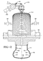
- the apparatus 100 has a guide means which has, in addition to the ply mechanism 70, a robotic computer controlled system 110 for placing the cord 2 onto the toroidal surface 50.
- a means for applying an elastomeric layer 4 onto the mandrel 52 is provided which can include a server mechanism to feed strips of the layer 4 to the mandrel 52.
- the robotic computer controlled system 110 has a computer 120 and preprogrammed software which dictates the ply path 10 to be used for a particular tire size. Each movement of the system 110 can be articulated with very precise movements.
- the robot 150 which is mounted on a pedestal 151 has a robotic arm 152 which can be moved in preferably six axes.
- the manipulating arm 152 has the ply mechanism 70 attached as shown.
- Loop end forming mechanisms 60 are positioned on each side 56 of the toroidal mandrel 52.
- the robotic arm 152 feeds the ply cord 2 in predetermined paths 10 and the loop end forming mechanism 60 holds the cord 2 in place as a looped end 12 is formed.
- the toroidal mandrel 52 is rotated to index to the next pitch P and the adjacent ply path 10 around the toroidal mandrel 52.
- the movement of the ply mechanism 70 permits convex curvatures to be coupled to concave curvatures near the bead areas thus mimicking the as molded shape of the tire.
- a means 63 for rotating the mandrel 52 about its axle 64 are all mounted to a rigid frame 65 as shown.
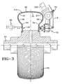
- a cross-sectional view of the toroidal mandrel 52 is shown.
- the radially inner portions 54 on each side 56 of the toroidal mandrel 52 have a concave curvature that extends radially outward toward the crown area 55 of the toroidal mandrel 52.
- the concave cross section extends radially outward toward the upper sidewall portion 57 the curvature transitions to a convex curvature in what is otherwise known as the crown area 55 of the toroidal mandrel 52.
- This cross section very closely duplicates the as molded cross section of a tire.
- the means for guiding the dispensed cords has a ply mechanism 70 as shown in a schematic form which illustrates how the ply cord 2 is laid onto an elastomeric surface 4 in a predetermined ply path 10.
- the schematic views simply illustrate the basic working components of the ply mechanism 70 and give a very good illustration of how the mechanism 70 works to place the cords 2 in a very precise location.
- the mechanism 70 which contains two pairs of parallel pins or rollers 40, 42 with the second pair 42 placed 90° relative to the first pair 40 and in a physical space of about one inch above the first pair 40 and forms a center opening 30 between the two pairs of rollers which enables the cord path 10 to be maintained in this center.
- the cords 2 are held in place by a combination of embedding the cord into the elastomeric compound 4 previously placed onto the toroidal surface 50 and the surface tackiness of the uncured compound. Once the cords 2 are properly applied around the entire circumference of the toroidal surface 50 a subsequent lamination of elastomeric topcoat compound (not shown) can be used to complete the construction of the ply 20.
- the bottom pair of rollers 40 uses a first roller 40A to embed the cord 2 on a forward traverse across the toroidal surface 50 as illustrated in Fig. 4 .
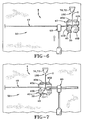
- the mechanism 100 stops and the holding mechanism and loop forming plate mechanism 60 advances onto the cord 2 and presses the cord 2 against the toroidal surface 50 as illustrated in Fig. 6 .
- the mechanism 100 then reverses its path 10 forming a loop 12 in the ply cord path 10.
- the second roller 40B of the first pair 40 pulls the cord 2 back across the toroidal surface 50.
- the top second pair 42 positions the cord 2 in a parallel path 10 and creates the spacing between the cords 2 hereinafter referred to as the pitch when the mandrel 52 having the toroidal surface 50 covered by the bottom coat compound laminate 4 advances for the return path.
- the toroidal surface 50 is indexed or advanced slightly allowing a circumferential spacing or pitch (P) to occur between the first ply pathway down in the second return ply path.
- P circumferential spacing or pitch
- the loop 12 that is formed on the reverse traverse is slightly shifted and therefore allowed to be pulled against the loop forming mechanism 60 as the cord 2 clinches against the pin to create the desired loop position.
- Fig. 7 the toroidal surface 50 is indexed or advanced slightly allowing a circumferential spacing or pitch (P) to occur between the first ply pathway down in the second return ply path.
- the loop 12 that is formed on the reverse traverse is slightly shifted and therefore allowed to be pulled against the loop forming mechanism 60 as the cord 2 clinches against the pin
- a looped end 12 is formed and the second ply path 10 is laid on the toroidal surface 50 parallel to the first ply path 10.
- the loop mechanism 60 then retracts and the second ply path 10 is finished.
- This process is repeated to form a series of cords 2 that are continuous and parallel within at least certain portions of the ply path 10. This is accomplished by having toroidal mandrel 52 with the toroidal surface 50 with an elastomeric compound 4 laminated onto it to index or advance uniformly about its axis with each traverse of the pair of rollers pins 40, 42 to create a linearly parallel path 10 uniformly distributed about the toroidal surface 50.
- By varying the advance of the cord 2 as the mechanism 100 traverses it is possible to create non-linear parallel cord paths 10 to tune tire stiffness and to vary flexure with the load.
- the cord 2 is wrapped around a tension or ply mechanism 70 to adjust and maintain the required tension in the cord 2. If it is too tight it will lift the cord from the coat laminate when the roller pins 40, 42 reverse direction. If it is too loose it will not create a loop at the correct length around the loop pin mechanism 60.
- tension on the cord 2 is created as it passes between a series of rollers 72 capable of adjusting and maintaining tension as needed for the process and the roller 40, 42. What is different about the present technique is that the amount of tension applied has to be sufficiently small that it does not lift the cords 2 from their placed position on the toroidal surface 50.
- the cord 2 is resting on the toroidal surface 50 positioned and stitched to an elastomeric layer 4 such that the tack between the cord 2 and the elastomeric layer 4 is larger than the tension applied by the ply mechanism 70.
- This permits the cords 2 to lay freely onto the toroidal surface 50 without moving or separating during the ply construction period. This is significantly different from the prior art mechanisms which required linear paths and required a large amount of tension to hold the cord paths 10 as the equipment is traversing over a convex surface to create a laminated ply.
- FIG. 11 attention is drawn to the three dimensional view of a cylinder representing how the ply path 10 is initiated along what would generally be considered the bead region 22 of the carcass 20 along the tire sidewall 24 toward the shoulder region 25 of the toroidal surface 50 and then traverses across the toroidal surface 50 in an area commonly referred to as the crown 26 as illustrated in Figure 11 .
- the ply cord path 10 is laid at a slight angle. While the ply path 10 may be at any angle including radially at 90° or less, the ply path 10 also can be applied in a non-linear fashion.
- the ply mechanism 70 can be provided with additional rollers 40 such that multiple paths 10 can be traversed around the toroidal surface 50.
- three dispensing spools 74 are shown traversing three rollers 40A, 40B, 40C that are spaced in a staggered sequence permitting the openings between each pair of rollers to continue to guide the cords 2 while the lower or bottom pair of rollers 40A, 40B provide the stitching of the cords 2 to the toroidal surface 50.
- the same loop mechanism 60 can be used for clinching the cords 2 at each loop end 12. As illustrated only one loop mechanism 60 is shown. However, it is understood that there would be a pair of loop mechanisms, one being on each side of the toroidal surface 50.
- a ply path 10 is shown whereby the loop ends 12B can be adjusted radially outwardly.
- the loop 12 while being part of a continuous strand of cord 2, is only partially shown going up to the sidewall 26 and terminating there.
- This continuous strand of cord 2 would create a path 10 whereby the loop ends 12B of the first set of adjacent pairs of cord paths 10 has loop ends 12B at a diameter slightly higher than the second pair of loop ends 12A. This is repeated in an alternating fashion.
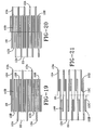
- This particular cord path 10 creates the cord path 10 as illustrated in Figure 18 shown in a lay flat position.
- toroidal shaped ply path 10 it is possible to maintain a uniform ply path all the way across the carcass structure. This enables the tire designer to possibly use finer cords or fewer cords and yet still achieve the same strength of present day tires.
- one long ply cord path 10A can be used across the tire and then the two short ply cord paths 10B can be applied, then one long cord ply path 10A on the opposite side.
- the long ply cord paths 10A are circumferentially offset on a pattern of two short paths 10B being between each circumferentially offset long ply cord paths 10A; thereby four such ply cord path short ends 12B are on each side between the long ends 12A as illustrated in Figure 19 .
- Figure 20 shows a ply path construction whereby only one such short ply cord path 10B is between circumferentially offset long paths 10A.
- each ply cord path 10 creates a circumferentially offset long ply path 10A.
- two ply cord paths 10A, 10B are shown that extend end to end in a repeating fashion.
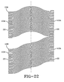
- the ply cord paths 10A, 10B as illustrated show the possibility of creating two layers.
- a first layer of parallel ply cord paths 10A is shown with a curvature in one direction.
- the second ply cord path 10B of Figure 22 could be a second layer of ply cord paths that could be applied continuously over the top of the first ply cord path 10A.
- Both of these ply cords paths 10A, 10B as illustrated in Figure 22 illustrate the ability to make nonlinear cord paths in a uniform fashion. This technique greatly facilitates the construction of true geodesic ply path cord tires as a viable and manufacturingly feasible tire.
- the ply 20 shows how a standard tire currently manufactured could be built where all the ply endings 12 are at the same location.
- predetermined ply paths 10 are designed such that the sidewall will have an increased number of cords extending up toward the crown area 26 but will stop short of crossing the crown 26 at loop end 12B and will return back traversing back and then create a continuous ply across the entire toroidal surface 50.
Landscapes
- Engineering & Computer Science (AREA)
- Mechanical Engineering (AREA)
- Tyre Moulding (AREA)
- Tires In General (AREA)
Applications Claiming Priority (2)
| Application Number | Priority Date | Filing Date | Title |
|---|---|---|---|
| US10/365,374 US20040154727A1 (en) | 2003-02-11 | 2003-02-11 | Method and apparatus for manufacturing carcass plies for a tire |
| US365374 | 2003-02-11 |
Publications (3)
| Publication Number | Publication Date |
|---|---|
| EP1447209A2 EP1447209A2 (en) | 2004-08-18 |
| EP1447209A3 EP1447209A3 (en) | 2005-10-05 |
| EP1447209B1 true EP1447209B1 (en) | 2008-04-09 |
Family
ID=32681712
Family Applications (1)
| Application Number | Title | Priority Date | Filing Date |
|---|---|---|---|
| EP04002543A Expired - Lifetime EP1447209B1 (en) | 2003-02-11 | 2004-02-05 | Method for manufacturing carcass plies for a tire |
Country Status (5)
| Country | Link |
|---|---|
| US (2) | US20040154727A1 (enExample) |
| EP (1) | EP1447209B1 (enExample) |
| JP (1) | JP4746274B2 (enExample) |
| BR (1) | BRPI0400211B1 (enExample) |
| DE (1) | DE602004012908T2 (enExample) |
Families Citing this family (27)
| Publication number | Priority date | Publication date | Assignee | Title |
|---|---|---|---|---|
| EP1463627A1 (fr) * | 2001-12-28 | 2004-10-06 | Société de Technologie Michelin | Methode de pose de fils de structure de renfort pour pneumatique |
| US20040154727A1 (en) * | 2003-02-11 | 2004-08-12 | Weissert James Thomas | Method and apparatus for manufacturing carcass plies for a tire |
| JP2006514589A (ja) * | 2003-04-18 | 2006-05-11 | ピレリ・プネウマティチ・ソチエタ・ペル・アツィオーニ | 車輪用タイヤとその製造方法 |
| JP4776194B2 (ja) * | 2004-09-08 | 2011-09-21 | 株式会社ブリヂストン | 帯状部材の貼付け装置および貼付け方法 |
| FR2877873B1 (fr) * | 2004-11-12 | 2007-02-09 | Michelin Soc Tech | Appareil de fabrication d'un renforcement pour pneumatique |
| JP4540452B2 (ja) | 2004-11-19 | 2010-09-08 | 株式会社ブリヂストン | 空気入りタイヤの製造装置及び製造方法 |
| US20070125482A1 (en) * | 2005-12-01 | 2007-06-07 | Weissert James T | Bi-directional tooling head and method for tire cord application |
| US7686053B2 (en) | 2005-12-01 | 2010-03-30 | The Goodyear Tire & Rubber Company | Cord tensioning and feed mechanism for a tire cord applicator head |
| US20070125471A1 (en) | 2005-12-01 | 2007-06-07 | Weissert James T | Split cord geodesic configurations for a tire |
| US7753098B2 (en) | 2005-12-01 | 2010-07-13 | The Goodyear Tire & Rubber Company | Spring loaded tooling head and method for tire cord application |
| US20070125478A1 (en) * | 2005-12-01 | 2007-06-07 | Weissert James T | Tire cord application station and method |
| US8578994B2 (en) * | 2006-12-19 | 2013-11-12 | The Goodyear Tire & Rubber Company | Applicator head for tire cord construction |
| US20090133797A1 (en) * | 2007-11-27 | 2009-05-28 | The Goodyear Tire & Rubber Company | Pneumatic tire |
| US8535465B2 (en) * | 2007-11-30 | 2013-09-17 | Pirelli Tyre S.P.A. | Process and apparatus for manufacturing tyres for vehicle wheels |
| US20110146871A1 (en) * | 2009-12-23 | 2011-06-23 | Richard Frank Laske | Self-supporting pneumatic tire |
| US9421825B2 (en) * | 2009-12-23 | 2016-08-23 | The Goodyear Tire & Rubber Company | Geodesic belted tire |
| US8973635B2 (en) * | 2009-12-23 | 2015-03-10 | The Goodyear Tire & Rubber Company | Pneumatic tire with carcass cord strip wound in specified pattern |
| US8845836B2 (en) | 2009-12-23 | 2014-09-30 | The Goodyear Tire & Rubber Company | Geodesic tire and method of manufacture |
| US20120085477A1 (en) * | 2010-10-07 | 2012-04-12 | Yves Donckels | Pneumatic tire with a woven or knitted reinforcement |
| IT1403131B1 (it) * | 2010-12-14 | 2013-10-04 | Pirelli | Processo ed apparato per realizzare una struttura di rinforzo di un pneumatico per ruote di veicoli. |
| US9073278B2 (en) | 2011-10-27 | 2015-07-07 | The Goodyear Tire & Rubber Company | Geodesic pneumatic tire with braided carcass |
| US10307980B2 (en) | 2013-02-20 | 2019-06-04 | The Goodyear Tire & Rubber Company | Tire building applicator members and systems |
| JP5970032B2 (ja) * | 2014-08-06 | 2016-08-17 | 住友ゴム工業株式会社 | プライ材料の製造方法 |
| WO2017213763A1 (en) * | 2016-06-07 | 2017-12-14 | Bridgestone Americas Tire Operations, Llc | Tire building machine |
| JP6708230B2 (ja) * | 2018-08-07 | 2020-06-10 | 横浜ゴム株式会社 | 空気入りタイヤの製造方法および成形装置 |
| JP7713857B2 (ja) * | 2021-11-01 | 2025-07-28 | 株式会社ブリヂストン | エンドエフェクタ、ロボットおよび生産システム |
| FR3156792A1 (fr) * | 2023-12-19 | 2025-06-20 | Compagnie Generale Des Etablissements Michelin | Composite d’élastomère avec une pluralité d’éléments de renfort cousu selon une direction principale |
Family Cites Families (81)
| Publication number | Priority date | Publication date | Assignee | Title |
|---|---|---|---|---|
| US3002874A (en) * | 1955-02-01 | 1961-10-03 | Dunlop Tire & Rubber Corp | Apparatus for the manufacture of pneumatic tyres |
| BE565709A (enExample) * | 1957-03-14 | Michelin & Cie | ||
| DE1131000B (de) * | 1957-08-05 | 1962-06-07 | Pirelli | Verfahren und Vorrichtung zur Herstellung ringfoermiger Baender aus mindestens einem durchgehenden Faden auf einer Trommel mit einziehbarem Kranz, insbesondere zur Herstellung von Verstaerkungslagen fuer Kraftfahrzeug-luftreifen |
| US3183134A (en) * | 1962-04-03 | 1965-05-11 | Fairchild Hiller Corp | Tire building apparatus and method |
| US3310093A (en) * | 1965-05-21 | 1967-03-21 | Nat Standard Co | Restrictive tread component for pneumatic tires |
| US3422874A (en) * | 1965-10-18 | 1969-01-21 | Deering Milliken Res Corp | Tire and method of making it by applying strip of rubber coated continuous tire cord of low extensibility to the carcass in flat form and simultaneously shaping and vulcanizing to final tire shape |
| US3721599A (en) * | 1968-05-20 | 1973-03-20 | Deering Milliken Res Corp | Method and apparatus for securing a continuous thread on a support surface |
| US3802982A (en) * | 1970-01-06 | 1974-04-09 | Steelastic Co | Reinforced tire fabric and method and apparatus for making same |
| US3776792A (en) * | 1971-02-25 | 1973-12-04 | Caterpillar Tractor Co | Method for forming belted oval pneumatic tube-tires |
| FR2132509B1 (enExample) * | 1971-04-05 | 1974-03-08 | Kleber Colombes | |
| US3748203A (en) * | 1971-04-12 | 1973-07-24 | Deering Milliken Res Corp | Method and apparatus for positioning a plurality of continuous stripson a support surface |
| US3774662A (en) * | 1971-07-08 | 1973-11-27 | Uniroyal Inc | Production of high soft stretch tapes of reinforcing cords for molded elastomeric articles |
| FR2224313B1 (enExample) * | 1973-04-09 | 1976-05-21 | Michelin & Cie | |
| FR2278509A1 (fr) * | 1974-03-29 | 1976-02-13 | Kleber Colombes | Pneumatiques pour vehicules |
| US3939671A (en) * | 1974-06-10 | 1976-02-24 | Lawson-Hemphill, Inc. | Machine for knitting cord-like structures |
| US3998986A (en) * | 1975-02-03 | 1976-12-21 | Uniroyal Inc. | Conveyor belt of rubber reinforced with stitch-bonded web fabric |
| US4279285A (en) * | 1978-01-09 | 1981-07-21 | Caterpillar Tractor Co. | Apparatus and method for forming a tube article on a core |
| EP0113717B1 (en) * | 1982-07-19 | 1987-12-23 | The Boeing Company | Method and apparatus for fiber lamination |
| FR2597784B1 (fr) * | 1986-04-25 | 1990-10-26 | Michelin & Cie | Procede et appareil de fabrication de renforcements pour pneumatiques |
| FR2599297B1 (fr) * | 1986-06-02 | 1988-08-12 | Michelin & Cie | Procede et machine de fabrication d'un renforcement pour pneumatiques |
| US5221406A (en) * | 1986-09-17 | 1993-06-22 | Compagnie Generale Des Etablissements Michelin | Apparatus for manufacturing a tire by the laying of rubber products onto a rotating core |
| FR2603841B1 (fr) * | 1986-09-17 | 1989-02-24 | Michelin & Cie | Procede de fabrication d'un pneumatique avec pose des produits caoutchouteux et des elements de renforcement sur un support, dispositif de pose des produits caoutchouteux et machine qui utilise de tel(s) dispositif(s) |
| US5171394A (en) * | 1986-09-17 | 1992-12-15 | Compagnie Generale Des Etablissements Michelin | Method and apparatus of manufacturing a tire by the laying of rubber products onto a firm support |
| US4838966A (en) * | 1986-11-12 | 1989-06-13 | The Armstrong Rubber Co. | Woven endless tire reinforcing belt and method for producing same |
| US4830781A (en) * | 1987-09-18 | 1989-05-16 | The Armstrong Rubber Company | Tire body reinforcing component and apparatus and method for producing same |
| JP2532913B2 (ja) * | 1988-03-30 | 1996-09-11 | 株式会社ブリヂストン | タイヤ用補強部材の製造方法 |
| DE4021450A1 (de) * | 1990-07-05 | 1992-01-09 | Uniroyal Englebert Gmbh | Fahrzeugluftreifen |
| FR2677578A1 (fr) * | 1991-06-17 | 1992-12-18 | Sedepro | Procede de fabrication d'un pneumatique et machines pour la mise en óoeuvre de ce procede. |
| IT1250561B (it) * | 1991-12-30 | 1995-04-20 | Firestone Int Dev Spa | Metodo per la realizzazione di una carcassa toroidale per un pneumatico di veicolo stradale e carcassa ottenuta con il metodo. |
| IT1250560B (it) * | 1991-12-30 | 1995-04-20 | Firestone Int Dev Spa | Metodo e dispositivo per la realizzazione di una carcassa toroidale per un pneumatico di veicolo stradale. |
| ATE148028T1 (de) * | 1992-07-21 | 1997-02-15 | Sedepro | Verfahren und vorrichtung zum anordnen eines einfädigen verstärkungsdrahtes auf einen kern bei der herstellung von reifenkarkassen |
| FR2694519A1 (fr) * | 1992-08-07 | 1994-02-11 | Sedepro | Procédé de fabrication d'un pneumatique et machine de fabrication d'un renfort de sommet pour pneumatique. |
| FR2804367B1 (fr) * | 2000-02-01 | 2002-09-20 | Sedepro | Appareil a bras oscillant, pour la fabrication d'un renfort de pneumatique a partir d'un seul fil |
| US5465773A (en) * | 1993-04-30 | 1995-11-14 | Bridgestone Corporation | Pneumatic radial tires with zigzag belt and rubberized cord ply belt reinforcing layer |
| US5885387A (en) * | 1995-12-08 | 1999-03-23 | Sumitomo Rubber Industries, Ltd. | Pneumatic tire having endless carcass cord ply |
| FR2755904A1 (fr) * | 1996-11-21 | 1998-05-22 | Michelin & Cie | Renforcement de carcasse pour pneumatique, realise a partir d'un fil unique |
| DE69810200T2 (de) * | 1997-07-08 | 2003-11-13 | Bridgestone Corp., Tokio/Tokyo | Verfahren und Vorrichtung zum Aufbauen einer torusförmigen Reifenkarkasse |
| US6113833A (en) * | 1997-07-22 | 2000-09-05 | Bridgestone Corporation | Segmented toroidal core for manufacturing pneumatic tires |
| JP4131587B2 (ja) * | 1997-08-15 | 2008-08-13 | 株式会社ブリヂストン | 空気入りタイヤおよびその成形方法 |
| WO1999017920A1 (fr) * | 1997-10-03 | 1999-04-15 | Bridgestone Corporation | Procede et appareil pour former une couche de renfort d'un pneu |
| GB9724053D0 (en) * | 1997-11-15 | 1998-01-14 | Sumitomo Rubber Ind | Improved pneumatic tyre constructuon and manufacturing method |
| EP0943421B1 (en) * | 1997-11-28 | 2003-05-28 | Pirelli Pneumatici Societa' Per Azioni | A method for making tyres for vehicle wheels |
| US6318432B1 (en) * | 1997-11-28 | 2001-11-20 | Pirelli Pneumatici S.P.A. | Tire for vehicle wheels |
| DE69719771T2 (de) * | 1997-12-30 | 2003-12-11 | Pirelli Pneumatici S.P.A., Milano | Verfahren zur Herstellung von Luftreifen für Fahrzeugräder |
| JP3850968B2 (ja) * | 1998-01-07 | 2006-11-29 | 株式会社ブリヂストン | タイヤ補強コード配設装置および方法 |
| JP4233658B2 (ja) * | 1998-06-01 | 2009-03-04 | 株式会社ブリヂストン | カーカスコードの貼付け装置およびタイヤの製造方法 |
| DE19831747A1 (de) * | 1998-07-15 | 2000-01-20 | Continental Ag | Verfahren zur Herstellung eines Luftreifens |
| US6409959B1 (en) * | 1998-07-31 | 2002-06-25 | Pirelli Pneumatici S.P.A. | Process for manufacturing, moulding and curing tires for vehicle wheels |
| US6332999B1 (en) * | 1998-07-31 | 2001-12-25 | Pirelli Pneumatici S.P.A. | Method and apparatus for moulding and curing tires for vehicle wheels |
| US6941992B2 (en) * | 1998-10-30 | 2005-09-13 | Pirelli Pneumatici S.P.A. | Tire for a vehicle wheel and method of manufacturing the tire |
| KR100718257B1 (ko) * | 1998-10-30 | 2007-05-16 | 피렐리 타이어 소시에떼 퍼 아찌오니 | 차량 타이어용 카커스 구조체의 제조방법 및 상기 방법에 의해 얻어지는 카커스 구조체 |
| KR100724079B1 (ko) * | 1998-12-07 | 2007-06-04 | 피렐리 타이어 소시에떼 퍼 아찌오니 | 개량된 비드 구조물을 가진 차륜용 타이어 |
| KR100675773B1 (ko) * | 1998-12-17 | 2007-02-01 | 피렐리 타이어 소시에떼 퍼 아찌오니 | 차륜용 타이어 부품 제작 방법 및 장치 |
| TR200101839T2 (tr) * | 1998-12-23 | 2001-12-21 | Pirelli Pneumatici S.P.A. | Lastikler için bir karkasın imalat yöntemi ve bu yöntemle elde edilen bir karkas. |
| GB9900378D0 (en) * | 1999-01-09 | 1999-02-24 | Sumitomo Rubber Ind | Stitching ply edges into bead region |
| JP4358350B2 (ja) * | 1999-04-19 | 2009-11-04 | 株式会社ブリヂストン | タイヤ補強層の形成方法および装置 |
| US7597837B2 (en) * | 1999-06-25 | 2009-10-06 | Pirelli Pneumatici S.P.A. | Method and apparatus for moulding and curing tyres for vehicle wheels |
| JP2001096638A (ja) * | 1999-09-29 | 2001-04-10 | Bridgestone Corp | カーカスコードの貼付け装置およびタイヤの製造方法 |
| JP4315548B2 (ja) * | 1999-11-19 | 2009-08-19 | 株式会社ブリヂストン | タイヤカーカスの形成装置および形成方法 |
| ATE267082T1 (de) * | 1999-11-26 | 2004-06-15 | Pirelli | Verfahren und vorrichtung zur herstellung einer verstärkungsstruktur für fahrzeugluftreifen |
| ATE304442T1 (de) * | 1999-12-01 | 2005-09-15 | Pirelli | Anlage zur gleichzeitigen herstellung von verschiedenartigen reifen |
| FR2804368A1 (fr) * | 2000-02-01 | 2001-08-03 | Sedepro | Appareil pour la fabrication de renforts pour pneumatique |
| JP4436520B2 (ja) * | 2000-02-28 | 2010-03-24 | 株式会社ブリヂストン | 空気入りタイヤおよびそれの製造方法 |
| DE60113405T2 (de) * | 2000-05-26 | 2006-06-22 | Pirelli Pneumatici S.P.A. | Anlage zur simultanen herstellung von unterschiedlichen luftreifentypen |
| EP1195270A3 (en) * | 2000-10-03 | 2003-04-09 | Sumitomo Rubber Industries Ltd. | Pneumatic tyre |
| US6849146B2 (en) * | 2000-10-25 | 2005-02-01 | Toyo Tire & Rubber Co., Ltd. | Carcass ply producing apparatus, carcass ply producing method and pneumatic tire |
| DE60218771T2 (de) * | 2001-02-07 | 2007-12-13 | Société de Technologie Michelin | Schwingarmvorrichtung zur Herstellung einer Reifenverstärkungsstruktur mit einem einzigen Reifenkord |
| ES2252328T3 (es) * | 2001-02-07 | 2006-05-16 | Societe De Technologie Michelin | Aparato de brazo oscilante para la fabricacion de un refuerzo de neumatico a partir de un hilo. |
| JP2002347134A (ja) * | 2001-05-29 | 2002-12-04 | Bridgestone Corp | タイヤの製造方法およびカーカスコードの貼付け装置 |
| JP2003127246A (ja) * | 2001-10-29 | 2003-05-08 | Bridgestone Corp | タイヤの製造方法およびカーカスコードの貼付け装置 |
| DE60216636T2 (de) * | 2001-12-28 | 2007-09-20 | Société de Technologie Michelin | Reifen mit einer inneren und äusseren schlaufen bildenden verstärkungsstruktur |
| EP1463627A1 (fr) * | 2001-12-28 | 2004-10-06 | Société de Technologie Michelin | Methode de pose de fils de structure de renfort pour pneumatique |
| WO2003089258A1 (en) * | 2002-04-19 | 2003-10-30 | Bridgestone Corporation | Run flat tire and method of manufacturing the tire |
| AU2003238423A1 (en) * | 2002-06-03 | 2003-12-19 | Mechelin Recherche Et Technique S.A. | System for producing a reinforcing structure for a tyre with volumetric control of the die |
| JP4150216B2 (ja) * | 2002-06-14 | 2008-09-17 | 株式会社ブリヂストン | タイヤ製造方法、及び生タイヤ製造装置 |
| ATE340070T1 (de) * | 2002-12-04 | 2006-10-15 | Michelin Soc Tech | Vorrichtung zur herstellung eines verstärkungselements für grossformatige luftreifen |
| US6913378B2 (en) * | 2002-12-27 | 2005-07-05 | Quanta Display Incorporation | Direct-lighting type back light unit |
| FR2850320A1 (fr) * | 2003-01-23 | 2004-07-30 | Michelin Soc Tech | Appareil de fabrication d'un renforcement pour pneumatique, comportant un anneau de guidage |
| US20040154727A1 (en) * | 2003-02-11 | 2004-08-12 | Weissert James Thomas | Method and apparatus for manufacturing carcass plies for a tire |
| US6989067B2 (en) * | 2003-04-14 | 2006-01-24 | Roller Equipment Manufacturing Co., Inc. | Method and apparatus for application of material to core |
| US20050269009A1 (en) * | 2004-06-04 | 2005-12-08 | Steinke Richard A | Method and apparatus for forming a core of plies, belts and beads and for positioning the core in a mold for forming an elastomeric tire and the formed elastomeric tire |
-
2003
- 2003-02-11 US US10/365,374 patent/US20040154727A1/en not_active Abandoned
-
2004
- 2004-02-02 BR BRPI0400211-3A patent/BRPI0400211B1/pt not_active IP Right Cessation
- 2004-02-05 DE DE602004012908T patent/DE602004012908T2/de not_active Expired - Lifetime
- 2004-02-05 EP EP04002543A patent/EP1447209B1/en not_active Expired - Lifetime
- 2004-02-10 JP JP2004033402A patent/JP4746274B2/ja not_active Expired - Fee Related
-
2006
- 2006-03-28 US US11/390,675 patent/US20060162848A1/en not_active Abandoned
Also Published As
| Publication number | Publication date |
|---|---|
| US20040154727A1 (en) | 2004-08-12 |
| JP2004243770A (ja) | 2004-09-02 |
| JP4746274B2 (ja) | 2011-08-10 |
| DE602004012908D1 (de) | 2008-05-21 |
| BRPI0400211B1 (pt) | 2014-07-22 |
| BRPI0400211A (pt) | 2004-12-28 |
| EP1447209A3 (en) | 2005-10-05 |
| EP1447209A2 (en) | 2004-08-18 |
| DE602004012908T2 (de) | 2009-05-28 |
| US20060162848A1 (en) | 2006-07-27 |
Similar Documents
| Publication | Publication Date | Title |
|---|---|---|
| EP1447209B1 (en) | Method for manufacturing carcass plies for a tire | |
| EP2340947B1 (en) | Aircraft tire and method of manufacture | |
| EP2516145B1 (en) | Geodesic tire and method of its manufacture | |
| CN102762361B (zh) | 用于构造用于车辆车轮的生轮胎的处理和设备 | |
| EP2338699B1 (en) | Geodesic belted tire | |
| EP2439081B1 (en) | A pneumatic tire with a woven or knitted reinforcement | |
| JP2013047102A (ja) | タイヤおよびタイヤを製造する方法 | |
| RU2499670C2 (ru) | Способ и установка для производства шин для колес транспортного средства | |
| CN103228429B (zh) | 用于制造用于车辆车轮的轮胎的增强结构的方法和设备 | |
| US20130014878A1 (en) | Pneumatic tire | |
| US7275576B2 (en) | Method of making reinforcement elements for a vehicle tyre, and a tyre for a vehicle wheel | |
| EP1446279B1 (en) | Vehicle tyre provided with sidewall reinforcements. | |
| US20020124935A1 (en) | Carcass structure for vehicle-wheel tyres and its method of manufacturing | |
| EP1124699B1 (en) | Carcass structure for vehicle-wheel tyres and its method of manufacturing | |
| RU2363582C2 (ru) | Способ и установка для производства шин для колес транспортных средств | |
| KR101034604B1 (ko) | 차륜용 타이어 제조 방법 및 장치 | |
| RU2377128C2 (ru) | Способ и установка для производства шин для колес транспортного средства |
Legal Events
| Date | Code | Title | Description |
|---|---|---|---|
| PUAI | Public reference made under article 153(3) epc to a published international application that has entered the european phase |
Free format text: ORIGINAL CODE: 0009012 |
|
| AK | Designated contracting states |
Kind code of ref document: A2 Designated state(s): AT BE BG CH CY CZ DE DK EE ES FI FR GB GR HU IE IT LI LU MC NL PT RO SE SI SK TR |
|
| AX | Request for extension of the european patent |
Extension state: AL LT LV MK |
|
| PUAL | Search report despatched |
Free format text: ORIGINAL CODE: 0009013 |
|
| AK | Designated contracting states |
Kind code of ref document: A3 Designated state(s): AT BE BG CH CY CZ DE DK EE ES FI FR GB GR HU IE IT LI LU MC NL PT RO SE SI SK TR |
|
| AX | Request for extension of the european patent |
Extension state: AL LT LV MK |
|
| RIC1 | Information provided on ipc code assigned before grant |
Ipc: 7B 29D 30/16 A Ipc: 7B 60C 9/02 B |
|
| 17P | Request for examination filed |
Effective date: 20060405 |
|
| AKX | Designation fees paid |
Designated state(s): DE FR GB IT |
|
| 17Q | First examination report despatched |
Effective date: 20060602 |
|
| GRAP | Despatch of communication of intention to grant a patent |
Free format text: ORIGINAL CODE: EPIDOSNIGR1 |
|
| RIC1 | Information provided on ipc code assigned before grant |
Ipc: B29D 30/16 20060101AFI20070920BHEP Ipc: B29D 30/38 20060101ALI20070920BHEP Ipc: B60C 9/02 20060101ALI20070920BHEP |
|
| RTI1 | Title (correction) |
Free format text: METHOD FOR MANUFACTURING CARCASS PLIES FOR A TIRE |
|
| GRAS | Grant fee paid |
Free format text: ORIGINAL CODE: EPIDOSNIGR3 |
|
| GRAA | (expected) grant |
Free format text: ORIGINAL CODE: 0009210 |
|
| AK | Designated contracting states |
Kind code of ref document: B1 Designated state(s): DE FR GB IT |
|
| REG | Reference to a national code |
Ref country code: GB Ref legal event code: FG4D |
|
| REF | Corresponds to: |
Ref document number: 602004012908 Country of ref document: DE Date of ref document: 20080521 Kind code of ref document: P |
|
| ET | Fr: translation filed | ||
| PLBE | No opposition filed within time limit |
Free format text: ORIGINAL CODE: 0009261 |
|
| STAA | Information on the status of an ep patent application or granted ep patent |
Free format text: STATUS: NO OPPOSITION FILED WITHIN TIME LIMIT |
|
| 26N | No opposition filed |
Effective date: 20090112 |
|
| GBPC | Gb: european patent ceased through non-payment of renewal fee |
Effective date: 20090205 |
|
| PG25 | Lapsed in a contracting state [announced via postgrant information from national office to epo] |
Ref country code: GB Free format text: LAPSE BECAUSE OF NON-PAYMENT OF DUE FEES Effective date: 20090205 |
|
| PGFP | Annual fee paid to national office [announced via postgrant information from national office to epo] |
Ref country code: DE Payment date: 20140228 Year of fee payment: 11 |
|
| PGFP | Annual fee paid to national office [announced via postgrant information from national office to epo] |
Ref country code: FR Payment date: 20140128 Year of fee payment: 11 Ref country code: IT Payment date: 20140221 Year of fee payment: 11 |
|
| REG | Reference to a national code |
Ref country code: DE Ref legal event code: R119 Ref document number: 602004012908 Country of ref document: DE |
|
| REG | Reference to a national code |
Ref country code: FR Ref legal event code: ST Effective date: 20151030 |
|
| PG25 | Lapsed in a contracting state [announced via postgrant information from national office to epo] |
Ref country code: IT Free format text: LAPSE BECAUSE OF NON-PAYMENT OF DUE FEES Effective date: 20150205 |
|
| PG25 | Lapsed in a contracting state [announced via postgrant information from national office to epo] |
Ref country code: DE Free format text: LAPSE BECAUSE OF NON-PAYMENT OF DUE FEES Effective date: 20150901 |
|
| PG25 | Lapsed in a contracting state [announced via postgrant information from national office to epo] |
Ref country code: FR Free format text: LAPSE BECAUSE OF NON-PAYMENT OF DUE FEES Effective date: 20150302 |