EP1447139A2 - Auf einer Sammelleitung montierte automatische luftunterstützte Sprühpistole - Google Patents
Auf einer Sammelleitung montierte automatische luftunterstützte Sprühpistole Download PDFInfo
- Publication number
- EP1447139A2 EP1447139A2 EP03030040A EP03030040A EP1447139A2 EP 1447139 A2 EP1447139 A2 EP 1447139A2 EP 03030040 A EP03030040 A EP 03030040A EP 03030040 A EP03030040 A EP 03030040A EP 1447139 A2 EP1447139 A2 EP 1447139A2
- Authority
- EP
- European Patent Office
- Prior art keywords
- passageways
- coating material
- valve
- nozzle
- passageway
- Prior art date
- Legal status (The legal status is an assumption and is not a legal conclusion. Google has not performed a legal analysis and makes no representation as to the accuracy of the status listed.)
- Granted
Links
Images


Classifications
-
- B—PERFORMING OPERATIONS; TRANSPORTING
- B05—SPRAYING OR ATOMISING IN GENERAL; APPLYING FLUENT MATERIALS TO SURFACES, IN GENERAL
- B05B—SPRAYING APPARATUS; ATOMISING APPARATUS; NOZZLES
- B05B9/00—Spraying apparatus for discharge of liquids or other fluent material, without essentially mixing with gas or vapour
- B05B9/01—Spray pistols, discharge devices
-
- B—PERFORMING OPERATIONS; TRANSPORTING
- B05—SPRAYING OR ATOMISING IN GENERAL; APPLYING FLUENT MATERIALS TO SURFACES, IN GENERAL
- B05B—SPRAYING APPARATUS; ATOMISING APPARATUS; NOZZLES
- B05B7/00—Spraying apparatus for discharge of liquids or other fluent materials from two or more sources, e.g. of liquid and air, of powder and gas
- B05B7/02—Spray pistols; Apparatus for discharge
- B05B7/12—Spray pistols; Apparatus for discharge designed to control volume of flow, e.g. with adjustable passages
- B05B7/1254—Spray pistols; Apparatus for discharge designed to control volume of flow, e.g. with adjustable passages the controlling means being fluid actuated
- B05B7/1263—Spray pistols; Apparatus for discharge designed to control volume of flow, e.g. with adjustable passages the controlling means being fluid actuated pneumatically actuated
- B05B7/1272—Spray pistols; Apparatus for discharge designed to control volume of flow, e.g. with adjustable passages the controlling means being fluid actuated pneumatically actuated actuated by gas involved in spraying, i.e. exiting the nozzle, e.g. as a spraying or jet shaping gas
-
- B—PERFORMING OPERATIONS; TRANSPORTING
- B05—SPRAYING OR ATOMISING IN GENERAL; APPLYING FLUENT MATERIALS TO SURFACES, IN GENERAL
- B05B—SPRAYING APPARATUS; ATOMISING APPARATUS; NOZZLES
- B05B15/00—Details of spraying plant or spraying apparatus not otherwise provided for; Accessories
- B05B15/40—Filters located upstream of the spraying outlets
-
- B—PERFORMING OPERATIONS; TRANSPORTING
- B05—SPRAYING OR ATOMISING IN GENERAL; APPLYING FLUENT MATERIALS TO SURFACES, IN GENERAL
- B05B—SPRAYING APPARATUS; ATOMISING APPARATUS; NOZZLES
- B05B15/00—Details of spraying plant or spraying apparatus not otherwise provided for; Accessories
- B05B15/60—Arrangements for mounting, supporting or holding spraying apparatus
- B05B15/65—Mounting arrangements for fluid connection of the spraying apparatus or its outlets to flow conduits
-
- B—PERFORMING OPERATIONS; TRANSPORTING
- B05—SPRAYING OR ATOMISING IN GENERAL; APPLYING FLUENT MATERIALS TO SURFACES, IN GENERAL
- B05B—SPRAYING APPARATUS; ATOMISING APPARATUS; NOZZLES
- B05B7/00—Spraying apparatus for discharge of liquids or other fluent materials from two or more sources, e.g. of liquid and air, of powder and gas
- B05B7/0081—Apparatus supplied with low pressure gas, e.g. "hvlp"-guns; air supplied by a fan
-
- B—PERFORMING OPERATIONS; TRANSPORTING
- B05—SPRAYING OR ATOMISING IN GENERAL; APPLYING FLUENT MATERIALS TO SURFACES, IN GENERAL
- B05B—SPRAYING APPARATUS; ATOMISING APPARATUS; NOZZLES
- B05B7/00—Spraying apparatus for discharge of liquids or other fluent materials from two or more sources, e.g. of liquid and air, of powder and gas
- B05B7/02—Spray pistols; Apparatus for discharge
- B05B7/08—Spray pistols; Apparatus for discharge with separate outlet orifices, e.g. to form parallel jets, i.e. the axis of the jets being parallel, to form intersecting jets, i.e. the axis of the jets converging but not necessarily intersecting at a point
- B05B7/0807—Spray pistols; Apparatus for discharge with separate outlet orifices, e.g. to form parallel jets, i.e. the axis of the jets being parallel, to form intersecting jets, i.e. the axis of the jets converging but not necessarily intersecting at a point to form intersecting jets
- B05B7/0815—Spray pistols; Apparatus for discharge with separate outlet orifices, e.g. to form parallel jets, i.e. the axis of the jets being parallel, to form intersecting jets, i.e. the axis of the jets converging but not necessarily intersecting at a point to form intersecting jets with at least one gas jet intersecting a jet constituted by a liquid or a mixture containing a liquid for controlling the shape of the latter
-
- B—PERFORMING OPERATIONS; TRANSPORTING
- B05—SPRAYING OR ATOMISING IN GENERAL; APPLYING FLUENT MATERIALS TO SURFACES, IN GENERAL
- B05B—SPRAYING APPARATUS; ATOMISING APPARATUS; NOZZLES
- B05B7/00—Spraying apparatus for discharge of liquids or other fluent materials from two or more sources, e.g. of liquid and air, of powder and gas
- B05B7/24—Spraying apparatus for discharge of liquids or other fluent materials from two or more sources, e.g. of liquid and air, of powder and gas with means, e.g. a container, for supplying liquid or other fluent material to a discharge device
- B05B7/2489—Spraying apparatus for discharge of liquids or other fluent materials from two or more sources, e.g. of liquid and air, of powder and gas with means, e.g. a container, for supplying liquid or other fluent material to a discharge device an atomising fluid, e.g. a gas, being supplied to the discharge device
Definitions
- This invention relates to coating material atomizing and dispensing devices. It is disclosed in the context of an atomizer which uses (a) stream(s) of compressed gas or mixture of gases (hereinafter sometimes collectively "air") to shape the cloud of atomized material, sometimes referred to as an air-assisted, airless atomizer, or use (a) stream(s) of air to aid in atomization of the material to be atomized.
- air compressed gas or mixture of gases
- top,” bottom, front, rear, “left side,” “right side,” and the like refer to relative positions of components, devices and so on in the drawings, and are not intended as limitations on apparatus constructed according to the invention, orientations that apparatus constructed according to the invention can assume, or orientations in which such apparatus may be mounted. Nor should any such limitations be inferred.
- a coating material dispensing device includes a first component providing a connection to a source of coating material to be dispensed and a filter for filtering coating material to be dispensed.
- the first component includes a housing for housing the filter and a closure for selectively closing the housing to permit removal and replacement of the filter.
- the coating material dispensing device further includes a second component providing a nozzle through which the coating material is dispensed.
- the first and second components include first and second passageways, respectively. The first and second passageways communicate when the first and second components are assembled together to provide a flow of filtered coating material from the filter to the nozzle.
- the first component includes separate first and second portions.
- the first portion of the first component includes the housing, the closure and the first passageway.
- the second portion of the first component includes a control port for controlling a valve between the first passageway and the nozzle. The valve controls the flow of coating material from the nozzle.
- the first and second portions of the first component are constructed from different materials.
- the second component includes separate first and second portions.
- the first portion of the second component includes the second passageway and the nozzle.
- the second portion of the second component includes a mechanism for operating the valve.
- the first and second portions of the second component are constructed from different materials.
- the second component includes a mechanism for operating a first valve between the first passageway and the nozzle.
- the first valve controls the flow of coating material from the nozzle.
- the dispensing device includes a port for the introduction of a stream of compressed gas or mixture of gases into the stream of coating material dispensed from the nozzle.
- a third passageway supplies the stream of compressed gas or mixture of gases to the nozzle.
- a second valve controls the supply of compressed gas or mixture of gases from the port to the nozzle. The second valve is coupled to the mechanism for operating the first valve to be controlled by the mechanism for operating the first valve.
- the port is provided in the first component and the third passageway is provided in the second component.
- the apparatus further includes a fourth passageway provided in the first component and coupling the third passageway to the port.
- control port for controlling the valve comprises a port for introducing into the apparatus an operating fluid for operating the valve.
- the second component includes a mechanism for operating a first valve between the first passageway and the nozzle.
- the first valve controls the flow of coating material from the nozzle.
- the dispensing device includes a port for the introduction of multiple streams of compressed gas or mixture of gases into the stream of coating material dispensed from the nozzle.
- a third passageway supplies at least one of the multiple streams of compressed gas or mixture of gases to the nozzle.
- a second valve controls the supply of compressed gas or mixture of gases from the port to the nozzle.
- the second valve is coupled to the mechanism for operating the first valve to be controlled by the mechanism for operating the first valve.
- a fourth passageway supplies at least another of the multiple streams of compressed gas or mixture of gases to the nozzle.
- a third valve controls the supply of compressed gas or mixture of gases to the fourth passageway. The third valve is continuously adjustable to vary the amount of compressed gas or mixture of gases supplied through the fourth passageway.
- an air cap for retaining first means for providing a coating material dispensing orifice.
- the air cap includes a plurality of pairs of first passageways. The passageways of each pair of first passageways are oriented on opposite sides of the orifice to direct streams of compressed gas or mixture of gases onto the opposite sides of the first means to reduce the buildup of coating material on the first means.
- the apparatus includes at least three pairs of first passageways.
- a plane defined by intersecting lines extending longitudinally through the passageways of each pair of first passageways makes an angle of from about 20° to about 60° with a plane defined by intersecting lines extending longitudinally through the passageways of an adjacent pair of first passageways.
- a plane defined by intersecting lines extending longitudinally through the passageways of each pair of first passageways makes an angle of from about 30° to about 50° with a plane defined by intersecting lines extending longitudinally through the passageways of an adjacent pair of first passageways.
- a plane defined by intersecting lines extending longitudinally through the passageways of each pair of first passageways makes an angle of from about 40° with a plane defined by intersecting lines extending longitudinally through the passageways of an adjacent pair of first passageways.
- the apparatus includes at least one pair of second passageways.
- the second passageways of the at least one pair of second passageways are oriented on opposite sides of the orifice to direct streams of compressed gas or mixture of gases toward opposite sides of the stream of coating material dispensed through said coating material dispensing orifice to aid in atomization of coating material dispensed through the orifice.
- the at least one pair of second passageways includes at least one pair of second passageways whose longitudinal directions make angles of from about 40° to about 80° with the stream of coating material being dispensed through the orifice.
- the longitudinal directions of the at least one pair of second passageways make angles of from about 50° to about 70° with the stream of coating material being dispensed through the orifice.
- the longitudinal directions of the at least one pair of second passageways make angles of about 60° with the stream of coating material being dispensed through the orifice.
- the at least one pair of second passageways includes at least one pair of second passageways whose longitudinal directions extend generally perpendicularly to the stream of coating material being dispensed through the orifice.
- the apparatus includes at least one pair of third passageways.
- the passageways of each third pair of passageways are oriented on opposite sides of the orifice to direct streams of compressed gas or mixture of gases onto opposite margins of the stream of coating material dispensed from the coating material dispensing orifice.
- a coating material dispensing device includes a connection to a source of coating material to be dispensed, a nozzle through which the coating material is dispensed, and a first valve including a first valve component between the connection and the nozzle.
- the orientation of the first valve component controls the flow of coating material from the nozzle.
- the coating material dispensing device further includes a mechanism for changing the orientation of the first valve component. The mechanism and the first valve component are removable from the dispensing device as a unit.
- the apparatus includes a connection to a source of compressed gas or mixture of gases for dispensing with the coating material, and a second valve for controlling the dispensing of compressed gas or mixture of gases with the coating material.
- the second valve includes a component coupled to the mechanism.
- the condition of the second valve that is, whether it is open or closed, is controlled by the mechanism.
- the mechanism includes a piston and a cylinder in which the piston is reciprocable to move the first valve component to control the flow of coating material from the nozzle.
- the cylinder is closed by a closure.
- the first valve component and piston are removable from the coating material dispensing device by opening the closure and withdrawing the piston from the cylinder.
- the second valve component is mounted to the piston for movement with the piston.
- the second valve component is mounted to the piston from a closure side of the piston. This permits removal of the second valve component by removing the closure and removing the second valve component without having to remove the piston from the cylinder.
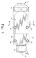
- An automatic manifold mount gun 20 is capable of being used as an air-assisted hydraulic atomizer, or in a high-volume, low-pressure (hereinafter sometimes HVLP) applications.
- Gun 20 is mounted on an air/fluid inlet junction manifold 22.
- Manifold 22 provides inlet fittings 24, 26, 28 for atomizing air, spray pattern-shaping air (hereinafter sometimes “fan air”), and the air supply to the piston 34 and cylinder 36 (Figs. 6-8) which operate the valve 38 (Fig. 6) which controls the flow of coating material from gun 20 (hereinafter sometimes "cylinder air”), respectively.
- Gun 20 generally produces a relatively flat, cat's-eye shaped, oval or elliptical cross section pattern with somewhat fan-shaped margins.
- the piston 34 is reciprocable in the cylinder 36 at a rearward end of gun 20.
- Piston 34 controls the opening and closing of coating material valve 38 at a forward end of gun 20 through a stem 40.
- Stem 40 is held in place in relation to piston 34 by a collet 42 and a collet locknut 44 which is threaded into the rearward end 46 of collet 42 and grips stem 40, capturing stem 40 in collet 42.
- the collet 42 is positioned in a passageway 48 through piston 34 by a retaining ring 50 which snaps into a groove 52 provided therefor in the collet 42 stem at a front face 54 of piston 34.
- the piston 34 is yieldably urged forward in its cylinder 36 by a piston spring 64 which is captured between a spring seat 66 provided on a rearward face 68 of piston 34 and a spring seat 70 formed on the inside of a cylinder end cap 74.
- Stem 40 extends through a cartridge assembly 80 which provides a seal around stem 40.
- Cartridge assembly 80 is of the general type, and generally for the purposes, described in U. S. Patent 6,272,616.
- Coating material to be dispensed from gun 20 is provided through either of two ports 82-1, 82-2 provided in manifold 22.
- the other of ports 82-1, 82-2 can be plugged with a threaded plug (not shown), or coupled through (a) suitable conduit(s) (not shown) to another gun 20 to supply coating material thereto, to recirculate coating material to the coating material source, such as a paint kitchen, or the like.
- Ports 82-1, 82-2 intersect a filter chamber 84 internally within manifold 22.
- Filter chamber 84 houses a filter 86 for the material to be dispensed.
- the filter may be, for example, a 100 mesh edge filter such as a Binks part number 54-1836 filter.
- Filter 86 is held removably in gun 20 by a threaded filter retainer assembly 87.
- a passageway 90 leads from filter chamber 84 to a surface 92 of manifold 22.
- a mating passageway 94 extends from a mating surface 96 of gun 20 and intersects a central passageway 98 which extends generally longitudinally of the body of gun 20. Passageway 94 intersects passageway 98 forward of cartridge assembly 80 which is threaded into passageway 98 from the cylinder 36 end of gun 20.
- a passageway 102 extends from cylinder air fitting 28 to surface 92 of manifold 22.
- a mating passageway 104 extends from surface 96 to cylinder 36 in front of a working surface of piston 34.
- a passageway 106 (Figs. 8 and 10) extends from atomizing air fitting 24 to surface 92 of manifold 22.
- a mating passageway 108 extends from surface 96 to, for example, an air-assisted hydraulic atomizing nozzle/air cap 110 (hereinafter sometimes referred to collectively as a "nozzle") at the front of gun 20.
- a passageway 112 (Figs. 7 and 10) extends from fan air fitting 26 to surface 92 of manifold 22.
- a mating passageway 114 (Fig. 10) extends from surface 96 to nozzle 110.
- Suitable seals 116 such as, for example, O-ring seals of materials suitably inert to the materials flowing through them, are provided at the mating surfaces 92, 96 around passageways 90, 94; 102, 104; 106, 108; and 112, 114 to seal these passageways against leakage.
- valve members 120-1 and 120-2 mounted to piston 34 and extending forward in passageways 108, 114, respectively, to points at which passageways 108, 114 turns from generally perpendicular to surface 96 to generally parallel to surface 96 as passageways 108, 114 progress forward toward nozzle 110.
- piston 34 starts rearward against the urging of spring 64.
- Coating material begins to flow from nozzle 110, the coating material being atomized by the pressure drop across nozzle 110.
- valve members 120-1, 120-2 open passageways 108, 114 and atomizing air and fan air flow forward to nozzle 110 is established.
- the valve members 120-1 and 120-2 are illustrated as being the same length, resulting in passageways 108, 114 being opened to the nozzle 110 substantially simultaneously.
- the time sequence and time delay among the supply of coating material, atomizing air and fan air to nozzle 110 may be controlled by selection of valve members 120-1 and 120-2 having appropriate lengths, which may be the same or different.
- the illustrated piston 34 configuration permits the piston 34 and its associated components, including the wire collet to be assembled into, and removed from, the gun 20, for example, to service the O-ring seals on the piston 34, or to service the cartridge assembly 80, or to service the atomizing or fan air valve members 120-1, 120-2.
- This construction also permits the atomizing and/or fan air valve members 120-1, 120-2 to be removed from the piston 34 without removing the piston 34 from the cylinder 36 by removing cap 74 and spring 64 and unscrewing atomizing and/or fan air valve members 120-1, 120-2 from rearward face 68 of piston 34.
- passageway 112 supplying fan air from fan air fitting 26 to passageway 114
- other means may be provided for supplying and regulating the supply of fan air through passageway 114 from the atomizing air supply coupled to fitting 24.
- a passageway 122 may be provided across manifold 22 from passageway 106 to passageway 114.
- Fitting 26 can be plugged, and flow from passageway 106 to passageway 114 may be controlled by a valve mechanism 125 (Fig. 9) including a valve needle 127 which threads into a packing 129. Packing 129 is threaded into passageway 122 from the passageway 112 side.
- Valve needle 127 can be threaded into packing 129 a desired distance from a valve seat 131 (see Fig. 10) provided in passageway 122 to obstruct all but the desired fan airflow from passageway 106 through passageway 122 to passageway 114 and thence to the fan air outlets from nozzle 110. In this way, the amount of air delivered from passageway 106 to passageway 114 to serve as fan air can be controlled at any desired level within the capacities of port 24 and passageways 106, 122, 112 and 114.
- a plug 133 may be inserted into passageway 122 at the valve seat 131, and the external opening of passageway 122 closed with a threaded plug 135 having the same relevant dimensions as packing 129. See Fig. 10.
- the manifold 22 includes a forward portion 150 and a rearward portion 152.
- the forward portion 150 which is exposed to the coating material being dispensed, is constructed from a material which is relatively unaffected by the coating material, for example, stainless steel.
- To reduce the weight of forward portion 150 it may be desirable to machine (a) cavity(ies) 154 in non-critical areas of the forward portion. Such cavities 154 are illustrated in the Figs. 6-8.
- the rearward portion which is exposed only to compressed air or the like, can be constructed from the same material, or from another, for example, lighter weight material, which is relatively unaffected by the compressed air. An example would be aluminum.
- the forward and rearward portions 150, 152, respectively, of the manifold are coupled together by dowel pins 156, one of which is illustrated in Fig. 8.
- the gun 20 also is divided into a forward portion 160 and a rearward portion 162. Alignment between the forward and rearward portions of the gun 20 is promoted by locating pins 166, one of which is illustrated in Fig. 7.
- the forward and rearward portions 160, 162 are coupled together by cap bolts 167 inserted into bores extending forward from cylinder 36 and threaded into threaded bores in the back surface 180 of forward portion 160.
- One of cap bolts 167 is illustrated in broken lines in Fig. 6.
- the forward portion 160 can be constructed from a material which is relatively unaffected by the coating material, for example, stainless steel, and the rearward portion from the same or a different material which is relatively unaffected by the compressed air.
- Gun 20 and manifold 22 are joined by cap bolts 168.
- Manifold 22 can be mounted on a rod (not shown). To accommodate such a mounting, a passageway 190 is provided through manifold 22 for receiving such a rod. A threaded opening 192 intersects passageway 190 to accommodate a locking bolt for fixing the position of manifold 22 along the length of such a rod. Manifold 22 can also be mounted to, for example, a suitable bracket, not shown. Threaded holes 194 and holes 196 for locating pins are provided in the bottom surface 198 of manifold 22 for this purpose.
- a weep port 200 extends through manifold 22.
- a passageway 202 intersects weep port 200 and extends to surface 92.
- a mating passageway 204 extends from mating surface 96 to central passageway 98 behind cartridge 80. The presence of coating material in weep port 200 provides an indication that cartridge 80 is compromised, and in need of service.
- Nozzle 110 includes a carbide tip assembly 208 including a spray orifice having a maximum dimension of, for example, .012" (about .3 mm.).
- the spray orifice may be circular, oval, cat's eye shaped, or any of a number of other desired shapes in cross section perpendicular to the nozzle 110 axis (in this case, generally perpendicular to the longitudinal extent of stem 40).
- Nozzle 110 also includes an air cap 210, details of which are best illustrated in Figs. 11-22.
- Carbide tip assembly 208 is retained in air cap 210.
- Air cap 210 is retained against an ultra high molecular weight polymer (UHMW) fluid seat assembly 212 (Fig. 6) by a threaded retaining ring 214 which is threaded onto the front of forward portion 160 of gun 20.
- O-ring 216 seals the air cap 210 to the UHMW fluid seat assembly 212.
- UHMW ultra high molecular weight polymer
- air cap 210 includes two diametrically opposed wings 220, each of which illustratively includes two passageways 222 which extend generally perpendicularly to facing, generally parallel surfaces 224 of the wings 220, and a passageway 226 which extends forward at an angle of, for example, 60° to the axis 228 of air cap 210.
- the axes of passageways 222 lie at distances of, for example, .050" on either side of a plane 230 which bisects air cap 210 and includes the axis 228.
- the axes of passageways 226 lie in the plane 230.
- the axes of passageways 222 lie a distance of, for example, .082" (about 2.1 mm) forward of the front face 232 of air cap 210.
- the axes of passageways 226 where passageways 226 open through surfaces 224 lie a distance of, for example, .044" (about 1.1 mm) forward of front face 232.
- Passageways 222 and 226 have diameters of, for example, .040" (about .9 mm).
- Passageways 233 are provided through the outer surfaces of wings 220, for example, to aid in machining passageways 222, 226. Passageways 233 are closed by appropriate plugs 235 which are then machined during the assembly of air cap 210. See Fig. 18. Atomizing air from passageway 108 is coupled through passageways 222 and 226 onto the spray exiting from tip 208 to assist in atomizing and shaping the spray.
- Six additional passageways 236 extend forwardly and radially inwardly at angles of, for example, 45° to the axis 228 of air cap 210.
- the axes of one diametrically opposed pair of passageways 236 lie generally in a plane 240 which bisects air cap 210 and lies generally parallel to surfaces 224.
- the axes of the remaining diametrically opposed pairs of passageways 236 lie generally in planes oriented at angles of, for example, 40° to plane 240, and intersect plane 240 on the axis 228 of air cap 210.
- Passageways 236 exit the face 232 of air cap 210 at a distance of, for example, about .218" (about 5.5 mm) from the axis 228 of air cap 210.
- Passageways 240 have diameters of, for example, .020" (about .5 mm). Atomizing air from passageway 108 is coupled through passageways 236 onto the spray exiting from tip 208 to assist in reducing the buildup of coating material on the carbide fluid tip 208 and on the air cap 210.
- An additional pair of diametrically opposed passageways 244 exit from the front face 232 of air cap 210 a distance of, for example, .352" (about 8.9 mm) from the axis 228 of air cap 210.
- the axes of passageways 236 make angles of, for example, 20° with the front face 232 of air cap 210. Shaping air from passageway 114 is coupled through passageways 244 onto the spray exiting from tip 208 to assist in atomizing and shaping the spray.
Landscapes
- Nozzles (AREA)
- Coating Apparatus (AREA)
- Filtering Of Dispersed Particles In Gases (AREA)
Priority Applications (2)
| Application Number | Priority Date | Filing Date | Title |
|---|---|---|---|
| EP06020649A EP1743704B1 (de) | 2003-02-13 | 2003-12-31 | Auf einer Sammelleitung montierte automatische luftunterstützte Sprühpistole |
| EP06020650A EP1743705A3 (de) | 2003-02-13 | 2003-12-31 | Auf einer Sammelleitung montierte automatische luftunterstützte Sprühpistole |
Applications Claiming Priority (2)
| Application Number | Priority Date | Filing Date | Title |
|---|---|---|---|
| US10/366,251 US6874708B2 (en) | 2003-02-13 | 2003-02-13 | Automatic air-assisted manifold mounted gun |
| US366251 | 2003-02-13 |
Related Child Applications (2)
| Application Number | Title | Priority Date | Filing Date |
|---|---|---|---|
| EP06020650A Division EP1743705A3 (de) | 2003-02-13 | 2003-12-31 | Auf einer Sammelleitung montierte automatische luftunterstützte Sprühpistole |
| EP06020649A Division EP1743704B1 (de) | 2003-02-13 | 2003-12-31 | Auf einer Sammelleitung montierte automatische luftunterstützte Sprühpistole |
Publications (3)
| Publication Number | Publication Date |
|---|---|
| EP1447139A2 true EP1447139A2 (de) | 2004-08-18 |
| EP1447139A3 EP1447139A3 (de) | 2006-04-12 |
| EP1447139B1 EP1447139B1 (de) | 2008-09-17 |
Family
ID=32681733
Family Applications (3)
| Application Number | Title | Priority Date | Filing Date |
|---|---|---|---|
| EP03030040A Expired - Fee Related EP1447139B1 (de) | 2003-02-13 | 2003-12-31 | Auf einer Sammelleitung montierte automatische luftunterstützte Sprühpistole |
| EP06020650A Withdrawn EP1743705A3 (de) | 2003-02-13 | 2003-12-31 | Auf einer Sammelleitung montierte automatische luftunterstützte Sprühpistole |
| EP06020649A Expired - Fee Related EP1743704B1 (de) | 2003-02-13 | 2003-12-31 | Auf einer Sammelleitung montierte automatische luftunterstützte Sprühpistole |
Family Applications After (2)
| Application Number | Title | Priority Date | Filing Date |
|---|---|---|---|
| EP06020650A Withdrawn EP1743705A3 (de) | 2003-02-13 | 2003-12-31 | Auf einer Sammelleitung montierte automatische luftunterstützte Sprühpistole |
| EP06020649A Expired - Fee Related EP1743704B1 (de) | 2003-02-13 | 2003-12-31 | Auf einer Sammelleitung montierte automatische luftunterstützte Sprühpistole |
Country Status (9)
| Country | Link |
|---|---|
| US (4) | US6874708B2 (de) |
| EP (3) | EP1447139B1 (de) |
| JP (1) | JP2004243318A (de) |
| KR (1) | KR101161391B1 (de) |
| CN (2) | CN1827229B (de) |
| CA (3) | CA2454872C (de) |
| DE (2) | DE60323597D1 (de) |
| MX (1) | MXPA04001439A (de) |
| TW (1) | TWI272972B (de) |
Cited By (2)
| Publication number | Priority date | Publication date | Assignee | Title |
|---|---|---|---|---|
| EP3100789A1 (de) * | 2015-06-05 | 2016-12-07 | J. Wagner AG | Automatik-spritzpistole zum versprühen eines fluids |
| WO2018047012A1 (de) * | 2016-09-12 | 2018-03-15 | Sata Gmbh & Co. Kg | Spritzvorrichtung zum druckluftzerstäubten spritzen in einem automatischen betrieb |
Families Citing this family (47)
| Publication number | Priority date | Publication date | Assignee | Title |
|---|---|---|---|---|
| US7617951B2 (en) * | 2002-01-28 | 2009-11-17 | Nordson Corporation | Compact heated air manifolds for adhesive application |
| US6874708B2 (en) * | 2003-02-13 | 2005-04-05 | Illinois Tool Works Inc. | Automatic air-assisted manifold mounted gun |
| US7296706B2 (en) * | 2004-02-24 | 2007-11-20 | Nordson Corporation | Method and system for supporting and/or aligning components of a liquid dispensing system |
| US20050242108A1 (en) * | 2004-04-30 | 2005-11-03 | Nordson Corporation | Liquid dispenser having individualized process air control |
| FR2872717B1 (fr) * | 2004-07-12 | 2006-09-15 | Itw Surfaces & Finitions Sa | Pistolet de pulverisation automatique comprenant un corps de pulverisation monte sur une embase d'alimentation |
| JP4171007B2 (ja) * | 2005-07-06 | 2008-10-22 | 本田技研工業株式会社 | 塗布ガンの洗浄方法 |
| US20070074656A1 (en) * | 2005-10-04 | 2007-04-05 | Zhibo Zhao | Non-clogging powder injector for a kinetic spray nozzle system |
| EP1973669B1 (de) * | 2006-01-06 | 2011-04-20 | Nordson Corporation | Flüssigkeitsspender mit individualisierter prozessluftsteuerung |
| JP2007275753A (ja) * | 2006-04-06 | 2007-10-25 | Toyota Motor Corp | 2液混合装置 |
| JP2008000649A (ja) * | 2006-06-20 | 2008-01-10 | Ransburg Ind Kk | ユニットタイプのスプレー装置 |
| FR2903027B1 (fr) * | 2006-07-03 | 2008-11-14 | Exel Ind Sa | Pistolet automatique de pulverisation |
| US7992667B2 (en) * | 2006-08-08 | 2011-08-09 | David Wayne Rennie | Oil cooling and filtering system, kit and apparatus |
| DE502007000825D1 (de) | 2006-12-05 | 2009-07-16 | Sata Gmbh & Co Kg | Belüftung für den Fließbecher einer Farbspritzpistole |
| KR100782756B1 (ko) * | 2006-12-21 | 2007-12-05 | 주식회사 포스코 | 유량 조절기가 설치된 냉간압연용 형상제어장치 |
| US20080217360A1 (en) * | 2007-03-05 | 2008-09-11 | Illinois Tool Works Inc. | Hot melt adhesive dispensing valve or module assembly having a module filter disposed therewithin |
| TWI432264B (zh) * | 2007-04-10 | 2014-04-01 | Graco Minnesota Inc | 可反轉的空氣輔助無空氣噴霧尖端 |
| CA2686395A1 (en) * | 2007-05-09 | 2008-11-20 | Nordson Corporation | Nozzle with internal ramp |
| US7970872B2 (en) * | 2007-10-01 | 2011-06-28 | Accenture Global Services Limited | Infrastructure for parallel programming of clusters of machines |
| US9188086B2 (en) * | 2008-01-07 | 2015-11-17 | Mcalister Technologies, Llc | Coupled thermochemical reactors and engines, and associated systems and methods |
| PL2265387T3 (pl) | 2008-03-12 | 2015-10-30 | Jeffrey D Fox | Jednorazowy wkład do pistoletu natryskowego |
| TWI546125B (zh) * | 2008-05-15 | 2016-08-21 | 格雷克明尼蘇達股份有限公司 | 快接式流體頭部 |
| US20140011318A1 (en) * | 2008-09-29 | 2014-01-09 | Sono-Tek Corporation | Methods and systems for ultrasonic spray shaping |
| US9004003B2 (en) * | 2009-06-25 | 2015-04-14 | Xerox Corporation | Apparatus for applying an acoustic dampening coating to the interior of a xerographic drum |
| DE102009032399A1 (de) | 2009-07-08 | 2011-01-13 | Sata Gmbh & Co. Kg | Farbspritzpistole |
| US9333519B2 (en) | 2010-12-02 | 2016-05-10 | Sata Gmbh & Co. Kg | Spray gun and accessories |
| EP2726212B2 (de) | 2011-06-30 | 2023-07-12 | SATA GmbH & Co. KG | Leicht zu reinigende spritzpistole, zubehör hierfür, montage- und demontageverfahren |
| WO2013031531A1 (ja) * | 2011-09-02 | 2013-03-07 | Shimada Takaji | 工具無しで分解組立可能な低吐出量用液体材料噴射バルブ |
| MX2014006531A (es) * | 2011-12-15 | 2014-07-14 | Graco Minnesota Inc | Filtro de extremo para valvula interna. |
| US8882085B1 (en) * | 2012-07-25 | 2014-11-11 | The United States Of America As Represented By The Secretary Of The Army | Micro atomizer |
| DE202013105779U1 (de) * | 2013-12-18 | 2015-03-19 | Sata Gmbh & Co. Kg | Luftdüsenabschluss für eine Lackierpistole |
| CN110560285B (zh) | 2014-07-31 | 2021-05-18 | 萨塔有限两合公司 | 喷枪及其制造方法 |
| CA159961S (en) | 2014-07-31 | 2015-07-17 | Sata Gmbh & Co Kg | Spray gun |
| USD768820S1 (en) | 2014-09-03 | 2016-10-11 | Sata Gmbh & Co. Kg | Paint spray gun with pattern |
| DE102015006484A1 (de) | 2015-05-22 | 2016-11-24 | Sata Gmbh & Co. Kg | Düsenanordnung für eine Spritzpistole, insbesondere Farbspritzpistole und Spritzpistole, insbesondere Farbspritzpistole |
| DE102015016474A1 (de) | 2015-12-21 | 2017-06-22 | Sata Gmbh & Co. Kg | Luftkappe und Düsenanordnung für eine Spritzpistole und Spritzpistole |
| CN205995666U (zh) | 2016-08-19 | 2017-03-08 | 萨塔有限两合公司 | 喷枪及其扳机 |
| CN205966208U (zh) | 2016-08-19 | 2017-02-22 | 萨塔有限两合公司 | 风帽组件以及喷枪 |
| DE102016011275B4 (de) | 2016-09-20 | 2023-06-15 | Raziol Zibulla & Sohn Gmbh | Vorrichtung, modulartiges System und Verfahren zum Aufbringen von flüssigem bis pastösem Befettungsmittel auf eine Werkstückoberfläche |
| WO2019202882A1 (ja) * | 2018-04-18 | 2019-10-24 | 株式会社三谷バルブ | 定量噴射ユニット |
| CN108906353B (zh) * | 2018-07-27 | 2019-10-29 | 江苏省中跃涂装设备有限公司 | 一种用于喷涂机器人的均匀喷涂出料口 |
| DE102018118738A1 (de) | 2018-08-01 | 2020-02-06 | Sata Gmbh & Co. Kg | Grundkörper für eine Spritzpistole, Spritzpistolen, Spritzpistolen-Set, Verfahren zur Herstellung eines Grundkörpers für eine Spritzpistole und Verfahren zum Umrüsten einer Spritzpistole |
| WO2018184636A2 (de) | 2018-08-01 | 2018-10-11 | Sata Gmbh & Co. Kg | Düsensatz für eine spritzpistole, spritzpistolensystem, verfahren zum ausgestalten eines düsen-moduls, verfahren zur auswahl eines düsen-moduls aus einem düsensatz für eine lackieraufgabe, auswahlsystem und computerprogrammprodukt |
| DE102018118737A1 (de) | 2018-08-01 | 2020-02-06 | Sata Gmbh & Co. Kg | Düse für eine Spritzpistole, Düsensatz für eine Spritzpistole, Spritzpistolen und Verfahren zur Herstellung einer Düse für eine Spritzpistole |
| CA3111295A1 (en) | 2018-10-26 | 2020-04-30 | Graco Minnesota Inc. | Fluid cartridge for a plural component sprayer |
| WO2020206241A1 (en) * | 2019-04-05 | 2020-10-08 | Nordson Corporation | Applicator air manifold |
| EP4232167A1 (de) * | 2020-10-20 | 2023-08-30 | Tyco Fire Products LP | Trockenrohrverteilersysteme und -verfahren |
| CN114985139B (zh) * | 2022-06-29 | 2023-05-02 | 浙江华朔科技股份有限公司 | 一种具有调节开关的喷头 |
Citations (12)
| Publication number | Priority date | Publication date | Assignee | Title |
|---|---|---|---|---|
| US2019941A (en) * | 1934-12-15 | 1935-11-05 | Vilbiss Co | Spray head |
| US3986672A (en) * | 1975-01-31 | 1976-10-19 | Smith Robert L | Spray gun system |
| US4219157A (en) * | 1977-03-10 | 1980-08-26 | S.K.M. | Hydrostatic paint atomization spray-gun |
| US4349153A (en) * | 1980-07-29 | 1982-09-14 | Champion Spark Plug Company | Spray nozzle |
| EP0456523A2 (de) * | 1990-05-11 | 1991-11-13 | Iwata Air Compressor Mfg. Co.,Ltd. | Niederdruck-Spritzpistole |
| FR2674773A1 (fr) * | 1991-04-08 | 1992-10-09 | Kremlin | Pistolet automatique pour projeter un produit de revetement sur des objets. |
| US5435491A (en) * | 1993-04-21 | 1995-07-25 | Alloy Kohki Co., Ltd. | Air mixed type spray apparatus |
| EP0672462A2 (de) * | 1994-03-16 | 1995-09-20 | Nordson Corporation | Flüssigkeitsapplikator |
| US6260583B1 (en) * | 2000-05-24 | 2001-07-17 | Illinois Tool Works Inc. | Segmented stackable head design |
| US6264113B1 (en) * | 1999-07-19 | 2001-07-24 | Steelcase Inc. | Fluid spraying system |
| US6422428B1 (en) * | 1998-04-20 | 2002-07-23 | Nordson Corporation | Segmented applicator for hot melt adhesives or other thermoplastic materials |
| EP1250963A1 (de) * | 2001-04-11 | 2002-10-23 | Illinois Tool Works Inc. | Düse zur Druckluftzerstäubung mit einer verbesserten Luftkappe |
Family Cites Families (51)
| Publication number | Priority date | Publication date | Assignee | Title |
|---|---|---|---|---|
| US26413A (en) * | 1859-12-13 | Poet able fence | ||
| US2070696A (en) * | 1935-12-11 | 1937-02-16 | Vilbiss Co | Spray head |
| US2646314A (en) * | 1950-10-19 | 1953-07-21 | Vilbiss Co | Spray nozzle |
| US3561680A (en) * | 1968-09-16 | 1971-02-09 | Respond Inc | Spray head assembly |
| US3746253A (en) * | 1970-09-21 | 1973-07-17 | Walberg & Co A | Coating system |
| US3912630A (en) * | 1972-10-24 | 1975-10-14 | Nordson Corp | Filter cartridge for thermoplastic applicator system |
| US4386739A (en) * | 1981-12-18 | 1983-06-07 | Graco Inc. | Nozzle for hydrostatic fluid tip |
| US4488665A (en) * | 1982-05-24 | 1984-12-18 | Spraymation, Inc. | Multiple-outlet adhesive applicator apparatus and method |
| US4854504A (en) * | 1983-11-04 | 1989-08-08 | Graves Spray Supply Co., Inc. | Fiberglass spray nozzle |
| DE3584522D1 (de) * | 1984-12-14 | 1991-11-28 | Gergely Gerhard | Teilchen aus einer hydrophoben oder schwerloeslichen substanz und verfahren zu ihrer hydrophilisierung. |
| DE3546462A1 (de) * | 1985-04-03 | 1986-10-16 | Mannesmann Kienzle Gmbh | Anordnung zur gasabscheidung |
| FR2595059B1 (fr) * | 1986-02-28 | 1988-06-17 | Sames Sa | Dispositif de pulverisation de liquide |
| DE3606479A1 (de) * | 1986-02-28 | 1987-09-03 | Basf Ag | Verfahren zur herstellung von polyoxibutylenpolyoxialkylenglykolen mit enger molekulargewichtsverteilung und vermindertem gehalt an oligomeren cyclischen ethern |
| DE3781578D1 (de) * | 1986-02-28 | 1992-10-15 | Siemens Ag | Drossel fuer hochleistungs-schaltnetzteil. |
| JPS62222013A (ja) * | 1986-03-22 | 1987-09-30 | Kawasaki Heavy Ind Ltd | サイホン式転炉出鋼口の炉体取付装置 |
| CA1274946A (en) | 1986-03-31 | 1990-10-02 | James Raymond Dell | Flame retardant high density rigid polyurethane foams |
| GB8608194D0 (en) * | 1986-04-03 | 1986-05-08 | Massey Ferguson Services Nv | Valve control system |
| GB8608609D0 (en) | 1986-04-09 | 1986-05-14 | Gen Electric Co Plc | Optical waveguide lenses |
| NL8600905A (nl) * | 1986-04-10 | 1987-11-02 | Philips Nv | Soldeerinrichting. |
| US4783363A (en) * | 1986-09-24 | 1988-11-08 | The Dow Chemical Company | Curable compositions containing a polyepoxide and a halogenated bisphenol |
| DE3705815A1 (de) * | 1987-02-24 | 1988-09-01 | Kopperschmidt Mueller & Co | Elektrostatische spruehpistole |
| US4763864A (en) * | 1987-10-13 | 1988-08-16 | O'connor Engineering Laboratories | Floating column support pedestal |
| GB8802130D0 (en) * | 1988-02-01 | 1988-03-02 | Devilbiss Co | Spraygun |
| FR2630930B1 (fr) * | 1988-05-03 | 1990-11-02 | Sames Sa | Dispositif de pulverisation pneumatique de liquide |
| US5165605A (en) * | 1989-03-30 | 1992-11-24 | Iwata Air Compressor Mfg. Co., Ltd. | Low pressure air atomizing spray gun |
| JP2549938B2 (ja) * | 1990-07-30 | 1996-10-30 | アロイ工器株式会社 | スプレー装置およびスプレー装置の制御装置 |
| DE4201665C2 (de) * | 1992-01-22 | 1993-10-28 | Wagner International Ag Altsta | Pulver-Injektor |
| ES2115700T3 (es) * | 1992-07-08 | 1998-07-01 | Nordson Corp | Aparato y procedimientos para la aplicacion de coberturas discretas. |
| US5344078A (en) * | 1993-04-22 | 1994-09-06 | Ransburg Corporation | Nozzle assembly for HVLP spray gun |
| US5535919A (en) * | 1993-10-27 | 1996-07-16 | Nordson Corporation | Apparatus for dispensing heated fluid materials |
| CN2171421Y (zh) * | 1993-10-30 | 1994-07-13 | 王扣成 | 多组分喷漆枪 |
| JP3256632B2 (ja) * | 1994-06-27 | 2002-02-12 | アネスト岩田株式会社 | 2液ポリエステル自動ガン |
| US5894994A (en) * | 1995-03-14 | 1999-04-20 | Nordson Corporation | Adjustable slot coating die |
| US5706982A (en) * | 1995-10-30 | 1998-01-13 | Nordson Corporation | Molten thermoplastic material supply system with distribution manifold having reverse flush filter and automatic drain |
| JPH1133471A (ja) * | 1997-07-23 | 1999-02-09 | Tokyo Electron Ltd | 塗布装置 |
| US5899387A (en) * | 1997-09-19 | 1999-05-04 | Spraying Systems Co. | Air assisted spray system |
| US6220843B1 (en) | 1998-03-13 | 2001-04-24 | Nordson Corporation | Segmented die for applying hot melt adhesives or other polymer melts |
| JPH11267554A (ja) * | 1998-03-24 | 1999-10-05 | Dyflex:Kk | 二液混合式スプレー方法およびその装置 |
| JP2000070818A (ja) * | 1998-09-03 | 2000-03-07 | San Tool:Kk | ホットメルト接着剤スプレー塗布装置における加熱装置 |
| KR100280770B1 (ko) * | 1999-02-18 | 2001-01-15 | 조현기 | 반도체 소자의 포터레지스터 디스팬싱장치 |
| FR2795347B1 (fr) * | 1999-06-23 | 2001-08-03 | Exel Ind | Pistolet automatique a membrane pour la pulverisation d'un produit |
| AU7484300A (en) | 1999-09-13 | 2001-06-04 | Sheffield Pharmaceuticals, Inc. | Aerosol airflow control system and method |
| US6276616B1 (en) * | 2000-04-07 | 2001-08-21 | Illinois Tool Works Inc. | Fluid needle loading assembly for an airless spray paint gun |
| JP4947330B2 (ja) | 2001-06-05 | 2012-06-06 | ノードソン株式会社 | 接着剤吐出装置のノズルキャップ |
| US7051904B2 (en) * | 2001-10-29 | 2006-05-30 | Nordson Corporation | Pump with integral filter for a hot melt adhesive system |
| US6991178B2 (en) * | 2003-01-24 | 2006-01-31 | Dürr Systems, Inc. | Concentric paint atomizer shaping air rings |
| US6874708B2 (en) * | 2003-02-13 | 2005-04-05 | Illinois Tool Works Inc. | Automatic air-assisted manifold mounted gun |
| US6899279B2 (en) * | 2003-08-25 | 2005-05-31 | Illinois Tool Works Inc. | Atomizer with low pressure area passages |
| US7237727B2 (en) * | 2004-04-13 | 2007-07-03 | Hsing-Tzu Wang | Paint spray gun |
| US7883026B2 (en) * | 2004-06-30 | 2011-02-08 | Illinois Tool Works Inc. | Fluid atomizing system and method |
| US20060027679A1 (en) * | 2004-08-03 | 2006-02-09 | Mr. Jack Gratteau | Ejector Nozzle |
-
2003
- 2003-02-13 US US10/366,251 patent/US6874708B2/en not_active Expired - Lifetime
- 2003-12-30 CA CA2454872A patent/CA2454872C/en not_active Expired - Fee Related
- 2003-12-30 CA CA2640510A patent/CA2640510C/en not_active Expired - Fee Related
- 2003-12-30 CA CA2640640A patent/CA2640640C/en not_active Expired - Fee Related
- 2003-12-31 DE DE60323597T patent/DE60323597D1/de not_active Expired - Lifetime
- 2003-12-31 EP EP03030040A patent/EP1447139B1/de not_active Expired - Fee Related
- 2003-12-31 DE DE60332670T patent/DE60332670D1/de not_active Expired - Lifetime
- 2003-12-31 EP EP06020650A patent/EP1743705A3/de not_active Withdrawn
- 2003-12-31 EP EP06020649A patent/EP1743704B1/de not_active Expired - Fee Related
-
2004
- 2004-01-29 KR KR1020040005588A patent/KR101161391B1/ko not_active IP Right Cessation
- 2004-02-03 JP JP2004026857A patent/JP2004243318A/ja not_active Ceased
- 2004-02-10 TW TW093103096A patent/TWI272972B/zh not_active IP Right Cessation
- 2004-02-13 CN CN2006100724225A patent/CN1827229B/zh not_active Expired - Fee Related
- 2004-02-13 CN CN2004100043287A patent/CN1520937B/zh not_active Expired - Fee Related
- 2004-02-13 MX MXPA04001439A patent/MXPA04001439A/es active IP Right Grant
- 2004-12-10 US US11/009,621 patent/US20050098654A1/en not_active Abandoned
- 2004-12-10 US US11/010,112 patent/US7059545B2/en not_active Expired - Lifetime
-
2007
- 2007-11-21 US US11/944,161 patent/US8622319B2/en not_active Expired - Fee Related
Patent Citations (12)
| Publication number | Priority date | Publication date | Assignee | Title |
|---|---|---|---|---|
| US2019941A (en) * | 1934-12-15 | 1935-11-05 | Vilbiss Co | Spray head |
| US3986672A (en) * | 1975-01-31 | 1976-10-19 | Smith Robert L | Spray gun system |
| US4219157A (en) * | 1977-03-10 | 1980-08-26 | S.K.M. | Hydrostatic paint atomization spray-gun |
| US4349153A (en) * | 1980-07-29 | 1982-09-14 | Champion Spark Plug Company | Spray nozzle |
| EP0456523A2 (de) * | 1990-05-11 | 1991-11-13 | Iwata Air Compressor Mfg. Co.,Ltd. | Niederdruck-Spritzpistole |
| FR2674773A1 (fr) * | 1991-04-08 | 1992-10-09 | Kremlin | Pistolet automatique pour projeter un produit de revetement sur des objets. |
| US5435491A (en) * | 1993-04-21 | 1995-07-25 | Alloy Kohki Co., Ltd. | Air mixed type spray apparatus |
| EP0672462A2 (de) * | 1994-03-16 | 1995-09-20 | Nordson Corporation | Flüssigkeitsapplikator |
| US6422428B1 (en) * | 1998-04-20 | 2002-07-23 | Nordson Corporation | Segmented applicator for hot melt adhesives or other thermoplastic materials |
| US6264113B1 (en) * | 1999-07-19 | 2001-07-24 | Steelcase Inc. | Fluid spraying system |
| US6260583B1 (en) * | 2000-05-24 | 2001-07-17 | Illinois Tool Works Inc. | Segmented stackable head design |
| EP1250963A1 (de) * | 2001-04-11 | 2002-10-23 | Illinois Tool Works Inc. | Düse zur Druckluftzerstäubung mit einer verbesserten Luftkappe |
Cited By (2)
| Publication number | Priority date | Publication date | Assignee | Title |
|---|---|---|---|---|
| EP3100789A1 (de) * | 2015-06-05 | 2016-12-07 | J. Wagner AG | Automatik-spritzpistole zum versprühen eines fluids |
| WO2018047012A1 (de) * | 2016-09-12 | 2018-03-15 | Sata Gmbh & Co. Kg | Spritzvorrichtung zum druckluftzerstäubten spritzen in einem automatischen betrieb |
Also Published As
| Publication number | Publication date |
|---|---|
| US6874708B2 (en) | 2005-04-05 |
| US20040195378A1 (en) | 2004-10-07 |
| US20080067184A1 (en) | 2008-03-20 |
| CN1827229A (zh) | 2006-09-06 |
| CA2640510C (en) | 2013-04-02 |
| KR20040073298A (ko) | 2004-08-19 |
| CA2640510A1 (en) | 2004-08-13 |
| CA2640640A1 (en) | 2004-08-13 |
| CN1827229B (zh) | 2010-05-12 |
| EP1743705A3 (de) | 2009-05-20 |
| TW200424019A (en) | 2004-11-16 |
| DE60332670D1 (de) | 2010-07-01 |
| CN1520937A (zh) | 2004-08-18 |
| CN1520937B (zh) | 2011-09-28 |
| US7059545B2 (en) | 2006-06-13 |
| EP1743705A2 (de) | 2007-01-17 |
| CA2640640C (en) | 2012-09-11 |
| EP1447139B1 (de) | 2008-09-17 |
| EP1743704A2 (de) | 2007-01-17 |
| EP1743704A3 (de) | 2009-05-20 |
| US20050098654A1 (en) | 2005-05-12 |
| KR101161391B1 (ko) | 2012-07-09 |
| DE60323597D1 (de) | 2008-10-30 |
| CA2454872C (en) | 2010-03-30 |
| EP1743704B1 (de) | 2010-05-19 |
| US20050098655A1 (en) | 2005-05-12 |
| MXPA04001439A (es) | 2004-08-18 |
| US8622319B2 (en) | 2014-01-07 |
| EP1447139A3 (de) | 2006-04-12 |
| JP2004243318A (ja) | 2004-09-02 |
| CA2454872A1 (en) | 2004-08-13 |
| TWI272972B (en) | 2007-02-11 |
Similar Documents
| Publication | Publication Date | Title |
|---|---|---|
| CA2640640C (en) | Automatic air-assisted manifold mounted gun | |
| US4993642A (en) | Paint spray gun | |
| CN100467136C (zh) | 具有手动可分离部分的喷液枪 | |
| US5271564A (en) | Spray gun extension | |
| EP1108476B1 (de) | Niederdruck-spritzpistole | |
| US9302281B2 (en) | High swirl air cap | |
| CN1278781C (zh) | 喷枪 | |
| US4915303A (en) | Paint spray gun | |
| US8123147B2 (en) | Powder coating system and components | |
| KR20170016937A (ko) | 외부 배플을 갖는 노즐 조립체 | |
| US4948053A (en) | Paint spray nozzle | |
| CA2987200A1 (en) | Nozzle assembly with auxiliary apertures | |
| US4905905A (en) | Paint spray nozzle | |
| US4917298A (en) | Method for spraying a fiber-containing fluid mixture using an air atomizing spray gun | |
| CN212143105U (zh) | 喷涂设备 | |
| US20030102392A1 (en) | Internal impingement nozzle | |
| AU2020289769A1 (en) | Cartridge used in liquid spraying gun for the use of disinfecting and coating surfaces | |
| JPH1080653A (ja) | 噴霧ノズルおよび流体材料を噴霧し吹きつける方法 | |
| JPH04134452U (ja) | 噴霧器 |
Legal Events
| Date | Code | Title | Description |
|---|---|---|---|
| PUAI | Public reference made under article 153(3) epc to a published international application that has entered the european phase |
Free format text: ORIGINAL CODE: 0009012 |
|
| AK | Designated contracting states |
Kind code of ref document: A2 Designated state(s): AT BE BG CH CY CZ DE DK EE ES FI FR GB GR HU IE IT LI LU MC NL PT RO SE SI SK TR |
|
| AX | Request for extension of the european patent |
Extension state: AL LT LV MK |
|
| PUAL | Search report despatched |
Free format text: ORIGINAL CODE: 0009013 |
|
| AK | Designated contracting states |
Kind code of ref document: A3 Designated state(s): AT BE BG CH CY CZ DE DK EE ES FI FR GB GR HU IE IT LI LU MC NL PT RO SE SI SK TR |
|
| AX | Request for extension of the european patent |
Extension state: AL LT LV MK |
|
| 17P | Request for examination filed |
Effective date: 20060505 |
|
| AKX | Designation fees paid |
Designated state(s): DE FR GB IT |
|
| GRAP | Despatch of communication of intention to grant a patent |
Free format text: ORIGINAL CODE: EPIDOSNIGR1 |
|
| GRAS | Grant fee paid |
Free format text: ORIGINAL CODE: EPIDOSNIGR3 |
|
| GRAA | (expected) grant |
Free format text: ORIGINAL CODE: 0009210 |
|
| AK | Designated contracting states |
Kind code of ref document: B1 Designated state(s): DE FR GB IT |
|
| REG | Reference to a national code |
Ref country code: GB Ref legal event code: FG4D |
|
| REF | Corresponds to: |
Ref document number: 60323597 Country of ref document: DE Date of ref document: 20081030 Kind code of ref document: P |
|
| PLBE | No opposition filed within time limit |
Free format text: ORIGINAL CODE: 0009261 |
|
| STAA | Information on the status of an ep patent application or granted ep patent |
Free format text: STATUS: NO OPPOSITION FILED WITHIN TIME LIMIT |
|
| 26N | No opposition filed |
Effective date: 20090618 |
|
| PGFP | Annual fee paid to national office [announced via postgrant information from national office to epo] |
Ref country code: IT Payment date: 20101223 Year of fee payment: 8 |
|
| PGFP | Annual fee paid to national office [announced via postgrant information from national office to epo] |
Ref country code: DE Payment date: 20101229 Year of fee payment: 8 |
|
| PGFP | Annual fee paid to national office [announced via postgrant information from national office to epo] |
Ref country code: FR Payment date: 20120503 Year of fee payment: 9 Ref country code: GB Payment date: 20120425 Year of fee payment: 9 |
|
| REG | Reference to a national code |
Ref country code: DE Ref legal event code: R119 Ref document number: 60323597 Country of ref document: DE Effective date: 20120703 |
|
| PG25 | Lapsed in a contracting state [announced via postgrant information from national office to epo] |
Ref country code: DE Free format text: LAPSE BECAUSE OF NON-PAYMENT OF DUE FEES Effective date: 20120703 |
|
| PG25 | Lapsed in a contracting state [announced via postgrant information from national office to epo] |
Ref country code: IT Free format text: LAPSE BECAUSE OF NON-PAYMENT OF DUE FEES Effective date: 20111231 |
|
| GBPC | Gb: european patent ceased through non-payment of renewal fee |
Effective date: 20121231 |
|
| REG | Reference to a national code |
Ref country code: FR Ref legal event code: ST Effective date: 20130830 |
|
| PG25 | Lapsed in a contracting state [announced via postgrant information from national office to epo] |
Ref country code: FR Free format text: LAPSE BECAUSE OF NON-PAYMENT OF DUE FEES Effective date: 20130102 Ref country code: GB Free format text: LAPSE BECAUSE OF NON-PAYMENT OF DUE FEES Effective date: 20121231 |
|
| REG | Reference to a national code |
Ref country code: GB Ref legal event code: 732E Free format text: REGISTERED BETWEEN 20150326 AND 20150401 |
|
| REG | Reference to a national code |
Ref country code: DE Ref legal event code: R081 Ref document number: 60323597 Country of ref document: DE Owner name: FINISHING BRANDS HOLDINGS INC., MINNEAPOLIS, US Free format text: FORMER OWNER: ILLINOIS TOOL WORKS INC., GLENVIEW, ILL., US |
|
| REG | Reference to a national code |
Ref country code: DE Ref legal event code: R082 Ref document number: 60323597 Country of ref document: DE |