EP1445395A1 - Système de toiture et procédé de couverture d'une toiture - Google Patents
Système de toiture et procédé de couverture d'une toiture Download PDFInfo
- Publication number
- EP1445395A1 EP1445395A1 EP04010173A EP04010173A EP1445395A1 EP 1445395 A1 EP1445395 A1 EP 1445395A1 EP 04010173 A EP04010173 A EP 04010173A EP 04010173 A EP04010173 A EP 04010173A EP 1445395 A1 EP1445395 A1 EP 1445395A1
- Authority
- EP
- European Patent Office
- Prior art keywords
- rail
- profile elements
- covering
- roof system
- roof
- Prior art date
- Legal status (The legal status is an assumption and is not a legal conclusion. Google has not performed a legal analysis and makes no representation as to the accuracy of the status listed.)
- Granted
Links
- 238000000034 method Methods 0.000 title claims abstract description 6
- 238000009413 insulation Methods 0.000 claims description 26
- 239000000853 adhesive Substances 0.000 claims description 22
- 230000001070 adhesive effect Effects 0.000 claims description 22
- 238000005520 cutting process Methods 0.000 claims description 5
- 230000003068 static effect Effects 0.000 description 7
- 239000000463 material Substances 0.000 description 6
- 229910052751 metal Inorganic materials 0.000 description 6
- 239000002184 metal Substances 0.000 description 6
- 229910001220 stainless steel Inorganic materials 0.000 description 5
- 239000010935 stainless steel Substances 0.000 description 5
- 239000011324 bead Substances 0.000 description 4
- 238000010276 construction Methods 0.000 description 4
- 229910000831 Steel Inorganic materials 0.000 description 3
- 230000004888 barrier function Effects 0.000 description 3
- 238000004049 embossing Methods 0.000 description 3
- 239000000835 fiber Substances 0.000 description 3
- 238000004519 manufacturing process Methods 0.000 description 3
- 239000010959 steel Substances 0.000 description 3
- 229910052782 aluminium Inorganic materials 0.000 description 2
- XAGFODPZIPBFFR-UHFFFAOYSA-N aluminium Chemical compound [Al] XAGFODPZIPBFFR-UHFFFAOYSA-N 0.000 description 2
- 238000005260 corrosion Methods 0.000 description 2
- 230000007797 corrosion Effects 0.000 description 2
- ATJFFYVFTNAWJD-UHFFFAOYSA-N Tin Chemical compound [Sn] ATJFFYVFTNAWJD-UHFFFAOYSA-N 0.000 description 1
- 238000004873 anchoring Methods 0.000 description 1
- 239000011248 coating agent Substances 0.000 description 1
- 238000000576 coating method Methods 0.000 description 1
- 238000009415 formwork Methods 0.000 description 1
- 239000012528 membrane Substances 0.000 description 1
- 230000000284 resting effect Effects 0.000 description 1
- 230000007704 transition Effects 0.000 description 1
Images


Classifications
-
- E—FIXED CONSTRUCTIONS
- E04—BUILDING
- E04D—ROOF COVERINGS; SKY-LIGHTS; GUTTERS; ROOF-WORKING TOOLS
- E04D3/00—Roof covering by making use of flat or curved slabs or stiff sheets
- E04D3/36—Connecting; Fastening
- E04D3/3601—Connecting; Fastening of roof covering supported by the roof structure with interposition of a insulating layer
- E04D3/3602—The fastening means comprising elongated profiles installed in or on the insulation layer
-
- E—FIXED CONSTRUCTIONS
- E04—BUILDING
- E04D—ROOF COVERINGS; SKY-LIGHTS; GUTTERS; ROOF-WORKING TOOLS
- E04D13/00—Special arrangements or devices in connection with roof coverings; Protection against birds; Roof drainage ; Sky-lights
- E04D13/16—Insulating devices or arrangements in so far as the roof covering is concerned, e.g. characterised by the material or composition of the roof insulating material or its integration in the roof structure
- E04D13/1606—Insulation of the roof covering characterised by its integration in the roof structure
- E04D13/1643—Insulation of the roof covering characterised by its integration in the roof structure the roof structure being formed by load bearing corrugated sheets, e.g. profiled sheet metal roofs
- E04D13/165—Double skin roofs
-
- F—MECHANICAL ENGINEERING; LIGHTING; HEATING; WEAPONS; BLASTING
- F02—COMBUSTION ENGINES; HOT-GAS OR COMBUSTION-PRODUCT ENGINE PLANTS
- F02M—SUPPLYING COMBUSTION ENGINES IN GENERAL WITH COMBUSTIBLE MIXTURES OR CONSTITUENTS THEREOF
- F02M69/00—Low-pressure fuel-injection apparatus ; Apparatus with both continuous and intermittent injection; Apparatus injecting different types of fuel
- F02M69/46—Details, component parts or accessories not provided for in, or of interest apart from, the apparatus covered by groups F02M69/02 - F02M69/44
- F02M69/54—Arrangement of fuel pressure regulators
-
- G—PHYSICS
- G05—CONTROLLING; REGULATING
- G05D—SYSTEMS FOR CONTROLLING OR REGULATING NON-ELECTRIC VARIABLES
- G05D16/00—Control of fluid pressure
- G05D16/04—Control of fluid pressure without auxiliary power
- G05D16/06—Control of fluid pressure without auxiliary power the sensing element being a flexible membrane, yielding to pressure, e.g. diaphragm, bellows, capsule
- G05D16/063—Control of fluid pressure without auxiliary power the sensing element being a flexible membrane, yielding to pressure, e.g. diaphragm, bellows, capsule the sensing element being a membrane
- G05D16/0644—Control of fluid pressure without auxiliary power the sensing element being a flexible membrane, yielding to pressure, e.g. diaphragm, bellows, capsule the sensing element being a membrane the membrane acting directly on the obturator
- G05D16/0655—Control of fluid pressure without auxiliary power the sensing element being a flexible membrane, yielding to pressure, e.g. diaphragm, bellows, capsule the sensing element being a membrane the membrane acting directly on the obturator using one spring-loaded membrane
- G05D16/0661—Control of fluid pressure without auxiliary power the sensing element being a flexible membrane, yielding to pressure, e.g. diaphragm, bellows, capsule the sensing element being a membrane the membrane acting directly on the obturator using one spring-loaded membrane characterised by the loading mechanisms of the membrane
-
- E—FIXED CONSTRUCTIONS
- E04—BUILDING
- E04C—STRUCTURAL ELEMENTS; BUILDING MATERIALS
- E04C3/00—Structural elongated elements designed for load-supporting
- E04C3/02—Joists; Girders, trusses, or trusslike structures, e.g. prefabricated; Lintels; Transoms; Braces
- E04C3/04—Joists; Girders, trusses, or trusslike structures, e.g. prefabricated; Lintels; Transoms; Braces of metal
- E04C2003/0404—Joists; Girders, trusses, or trusslike structures, e.g. prefabricated; Lintels; Transoms; Braces of metal beams, girders, or joists characterised by cross-sectional aspects
- E04C2003/0443—Joists; Girders, trusses, or trusslike structures, e.g. prefabricated; Lintels; Transoms; Braces of metal beams, girders, or joists characterised by cross-sectional aspects characterised by substantial shape of the cross-section
- E04C2003/0452—H- or I-shaped
-
- E—FIXED CONSTRUCTIONS
- E04—BUILDING
- E04D—ROOF COVERINGS; SKY-LIGHTS; GUTTERS; ROOF-WORKING TOOLS
- E04D3/00—Roof covering by making use of flat or curved slabs or stiff sheets
- E04D3/36—Connecting; Fastening
- E04D3/361—Connecting; Fastening by specially-profiled marginal portions of the slabs or sheets
- E04D2003/3615—Separate fastening elements fixed to the roof structure and consisting of parts permitting relative movement to each other, e.g. for thermal expansion
Definitions
- the invention relates to a roof system with an insulation plate, one Covering and profile elements and a method for covering a Roof.
- the invention is based on the object, this in practice in many cases to further improve the system used.
- the object on which the invention is based is achieved with a roof system solved with an insulation plate, a covering and profile elements, in which profile elements extending in a longitudinal direction therein Are arranged spaced in the longitudinal direction.
- Profile elements make it possible to adhere several on one profile element to be arranged at a defined distance and on site at the construction site the number by varying the distances between the profile elements of sticking to vary per square meter.
- Profile elements with a rail and an adhesive are used to a roof covering on a ceiling or a roof substructure Fasten.
- a bracket is z. B. for standing seam roofs, for Folded roofs or clamped roofs understood.
- the temples are made z. B. made of stainless steel, aluminum or galvanized coated steel.
- the ceiling forms the one shell and the Covering the other shell.
- This Profile element is connected to the ceiling or the substructure and the adhesive serves to attach a covering to the profile element.
- the profile elements are at least 0.3 m, preferably are spaced at least 0.5 m in the longitudinal direction. Such a distance between the profile elements reduces the cost of materials and the working time required on the construction site.
- the static Requirements are determined by the number of adherences per profile element Taken into account.
- the parallel lines are at least 0.2 m, are preferably arranged at least 0.3 m apart. hereby sufficient static strength with reduced workload achieved for laying the rails.
- the profile elements have at least one web have, which extends into the insulation plate.
- the web can do this be pressed into the insulation plate or anchored in a groove become.
- the profile elements have at least one web, that has a cutting edge.
- the cutting edge makes it easier to put the web in press in the insulation plate located under the profile element.
- the web end can be like a knife edge or designed as a zigzag line corresponding to a sawtooth cutting edge his.
- An advantageous embodiment variant provides that on the profile elements Adhesive are attached, which connect the covering with the rail. Such adhesion makes it possible, in particular sheet metal coverings easy to install.
- a free positioning of the profile elements on the insulation plate is achieved by the insulation plate resting on a ceiling surface, which is held by a supporting structure, and the profile elements on the Ceiling surface are attached.
- the ceiling area for example by a trapezoidal sheet used as the lower shell can be formed in this way be designed so that the profile elements on the ceiling surface can be attached.
- the problem underlying the invention also with solved a method for covering a roof, in which profile elements on an insulation plate on spaced lines spaced apart can be attached by using one under the insulation plate arranged ceiling to be connected and the adherence with a covering get connected.
- Opposite continuous U-profile rails enables the use of spaced apart in the longitudinal direction arranged profile elements the reduction in the number of adherences per Square meters while reducing the required for the rails Material.
- profile elements that have already been adhered to the supporting structure. If the profile elements already are equipped with adhesives before they are attached to the supporting structure, the working time on the construction site can be significantly reduced because the entire work step of connecting the adhesives to the profile elements can be omitted on site.
- connection between adhesive and rail a variety of connection options.
- the adhesive bonds have the disadvantage that the bonds do not meet the required static requirements (e.g. on wooden formwork) and therefore more adhesive must be used.
- the Embossed connection between the adhesive and the rail makes work much easier on site at the construction site, because the Manufacture of the profile elements can be stamped with the rail. Moreover enables the stamping of splint and adhesion the number of Reduce sticking, since the sticking embossed with the splint is higher static loads are sufficient as a conventional connection.
- the rail has an angled U-profile. This enables the rail to be pressed onto or into the insulation in this way, that part of the rail is anchored to or in the insulation.
- At least one side of the profile has a bead.
- Beading increase the stability of the profile and allow it to be thinner To use material thicknesses.
- one in the longitudinal direction of the profile extending bead are provided to prevent deformation of the Rail to counteract.
- the rail has a thickness of less than 1.6 mm, preferably less than 1.25 mm. hereby not only can considerable material be saved. The thin one Material strength also leads to a reduction in the weight of the rail and thus facilitates processing.
- the rail is galvanized. This allows a cheap one Use sheet metal without fear of corrosion. Rails made of aluminum or stainless steel can also be used which offer the same advantages.
- a pleasant look and protection of the surface of a metal rail is preferably achieved by coating the rail.
- the adhesive has a stainless steel part. hereby there will also be corrosion at the transition to covering and rail avoided.
- the rail has a length of less than 2 m, preferably less than 1 m and in particular less than 0.5 m.
- Straight short rail sections are inexpensive to manufacture, transport and facilitate the way of working on site on the roof to be covered. Moreover can the distance of the rail pieces by the short rail pieces to each other and thus the number of adherences per square meter simple way can be varied easily.
- a particularly advantageous embodiment variant provides that the adhesion is in several parts, with a fixed part being embossed with the rail and a variable part is displaceable relative to the fixed part. This leads to a defined play of the variable part of the adhesion relative to the rail, in order to expand the cover as a result of the To ensure temperature influence.
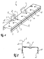
- the profile element 1 shown in Figure 1 consists essentially of the U-shaped rail 2 and the clips 3 and 4.
- the U-shaped rail 2 has a base surface 5 on which seven holes are regularly spaced 6 to 12 are attached.
- the holes are on the center line of the Longitudinal extension of the rail 1 and are with a chamfered edge 13 Mistake. This means that on the one hand the chamfered edge 13 of the Holes 6 to 12 when installing in the one under the rail Insulation plate (not shown) and on the other hand pressed into the bore Countersunk screw used (not shown) to a flat surface the base 5 of the rail 2 leads.
- each a bead 16 or 17 extends over the longitudinal extent of the rail.
- the width of the webs 14 and 15 is slightly less than half the Width of the base area 5.
- the rail 2 shown in the embodiment has a length of 350 mm and a width of 60 mm, while the length of the webs 25 mm is.
- the 4.6 mm wide beads allow the rail to be made from one Manufacture 1.15 mm thick steel sheet. This steel sheet is galvanized and coated.
- One third of the rail length from the end of the rail is open the base 5, an adhesive 3 or 4 arranged.
- the liability persists from an essentially Z-shaped angled stainless steel sheet a thickness of 0.4 mm. They have two on their contact surface 18 spaced points 19 and 20, where they with the base 5 of the Rail 2 are stamped. Prevent the spaced embossing points 19 and 20 a twisting of the adhesive 3 relative to the rail 2 and ensure a high static stability of the connection between the bond 3 and the rail 2.
- the adhesive 3 is arranged on the rail 2 so that the perpendicular to the base 18 extension 21 of the bond 3 in one Level with the leg 14 of the rail 2 extends.
- the further bond 4 is in a corresponding arrangement to the leg 14 of the rail 2 with the Embossed rail.
- the adherence thus lies on one to the longitudinal extent the rail 2 parallel line and allow sheet metal covering to connect with the rail.
- the adhesive used is 38 mm wide and angled in a U-shape at its end facing away from the rail to be folded in a known manner with a metal roof can.
- the profile element 30 shown in FIG. 6 has a rail 31 which is designed in accordance with the rail 2 shown in FIG. At this Rail 31, however, two-part adhesives 32 and 33 are arranged. This multi-part adhesion have a fixed part 34 or 35 and a variable Part 37, which is suspended in the fixed part 34 or 35.
- the fixed part 34 consists of an angled stainless steel sheet, the larger leg embossed at two points 38 and 39 with the rail 31 is.
- the shorter leg has a gap 40 into which the variable Part 36 of 32 is attached.
- the variable part 36 of the adhesive 32 is displaceable in the gap 40 because the longitudinal extent of the gap 40 is slightly larger than the width of the variable portion 36 of the tack 32.
- the two-part adhesive 32 thus enables the variable to be shifted Part 36 within predetermined limits relative to the fixed part 34 in order a necessary expansion of the roofing as a result of To ensure temperature influence.
- the detention 32 is designed accordingly.
- the execution of the adhesion as a two-part adhesion 32 also leads to the fact that the embossing points 38 and 39 are spaced further apart than in the one-piece Adhesions can be arranged and possibly more be provided as two embossing points on the fixed part of the adhesive 32 can.
- the fixed part 34 of the adhesive 32 has one Length of 90 mm and the variable part a width of 38 mm, so that the fixed part 34 protrudes on both sides of the variable part 36 by 26 mm.
- the bores in the rail are the same as in the exemplary embodiment shown in FIG. 1 arranged at a distance of 50 mm.
- a vapor barrier is placed on a lower shell to produce a double-skin roof system.
- a trapezoidal sheet for example, is suitable as the lower shell.
- An insulation plate such as a fiber insulation plate, is placed on the vapor barrier.
- This fiber insulation board is preferably accessible and has, for example, a bulk density of 120 kg / m 3 . Grooves are milled into the top of the fiber insulation board, into which the legs of the U-shaped rail of the profile element protrude. The rail is pressed into the insulation board until an essentially flat surface is created.
- profile elements are inserted in pre-milled grooves at a previously calculated distance and screwed to the lower shell using screws. The adhesions already attached to the profile elements then make it possible to attach an upper shell to the profile elements.
- a standing seam covering is suitable as an upper shell.
- profile element is suitable for any other coverings that are attachable by sticking.
Landscapes
- Engineering & Computer Science (AREA)
- Physics & Mathematics (AREA)
- Civil Engineering (AREA)
- Mechanical Engineering (AREA)
- Structural Engineering (AREA)
- Architecture (AREA)
- Chemical & Material Sciences (AREA)
- General Engineering & Computer Science (AREA)
- Automation & Control Theory (AREA)
- Combustion & Propulsion (AREA)
- General Physics & Mathematics (AREA)
- Fluid Mechanics (AREA)
- Roof Covering Using Slabs Or Stiff Sheets (AREA)
- Body Structure For Vehicles (AREA)
- Conveying And Assembling Of Building Elements In Situ (AREA)
- Fittings On The Vehicle Exterior For Carrying Loads, And Devices For Holding Or Mounting Articles (AREA)
- Radar Systems Or Details Thereof (AREA)
- Burglar Alarm Systems (AREA)
Priority Applications (1)
| Application Number | Priority Date | Filing Date | Title |
|---|---|---|---|
| DE20320692U DE20320692U1 (de) | 2002-03-20 | 2003-01-22 | Dachsystem mit einer Isolationsplatte, einer Eindeckung und Profilelementen |
Applications Claiming Priority (3)
| Application Number | Priority Date | Filing Date | Title |
|---|---|---|---|
| DE10212448 | 2002-03-20 | ||
| DE10212448A DE10212448A1 (de) | 2002-03-20 | 2002-03-20 | Profilelement mit einer Schiene und einer Hafte, Dachsystem und Verfahren zum Eindecken |
| EP03001426A EP1347116B1 (fr) | 2002-03-20 | 2003-01-22 | Elément profilé avec un rail et une patte de fixation, système de toiture et procédé de couverture d'une toiture |
Related Parent Applications (1)
| Application Number | Title | Priority Date | Filing Date |
|---|---|---|---|
| EP03001426A Division EP1347116B1 (fr) | 2002-03-20 | 2003-01-22 | Elément profilé avec un rail et une patte de fixation, système de toiture et procédé de couverture d'une toiture |
Publications (3)
| Publication Number | Publication Date |
|---|---|
| EP1445395A1 true EP1445395A1 (fr) | 2004-08-11 |
| EP1445395A8 EP1445395A8 (fr) | 2004-12-15 |
| EP1445395B1 EP1445395B1 (fr) | 2006-04-05 |
Family
ID=27771457
Family Applications (2)
| Application Number | Title | Priority Date | Filing Date |
|---|---|---|---|
| EP04010173A Expired - Lifetime EP1445395B1 (fr) | 2002-03-20 | 2003-01-22 | Système de toiture et procédé de couverture d'une toiture |
| EP03001426A Expired - Lifetime EP1347116B1 (fr) | 2002-03-20 | 2003-01-22 | Elément profilé avec un rail et une patte de fixation, système de toiture et procédé de couverture d'une toiture |
Family Applications After (1)
| Application Number | Title | Priority Date | Filing Date |
|---|---|---|---|
| EP03001426A Expired - Lifetime EP1347116B1 (fr) | 2002-03-20 | 2003-01-22 | Elément profilé avec un rail et une patte de fixation, système de toiture et procédé de couverture d'une toiture |
Country Status (6)
| Country | Link |
|---|---|
| EP (2) | EP1445395B1 (fr) |
| AT (2) | ATE322591T1 (fr) |
| DE (4) | DE10212448A1 (fr) |
| DK (2) | DK1445395T3 (fr) |
| ES (2) | ES2262062T3 (fr) |
| PT (1) | PT1347116E (fr) |
Cited By (2)
| Publication number | Priority date | Publication date | Assignee | Title |
|---|---|---|---|---|
| WO2006027180A1 (fr) * | 2004-09-07 | 2006-03-16 | Deutsche Rockwool Mineralwoll Gmbh & Co. Ohg | Dispositif servant a fixer des elements isolants sur l'ossature porteuse d'un toit et toit de batiment |
| WO2006027181A1 (fr) * | 2004-09-07 | 2006-03-16 | Deutsche Rockwool Mineralwoll Gmbh & Co. Ohg | Dispositif servant a fixer des elements isolants sur l'ossature porteuse d'un toit et toit de batiment |
Citations (5)
| Publication number | Priority date | Publication date | Assignee | Title |
|---|---|---|---|---|
| US4348846A (en) * | 1980-10-02 | 1982-09-14 | Butler Manufacturing Company | Insulated roof |
| US4435937A (en) * | 1982-03-08 | 1984-03-13 | Armco Inc. | Concealed fastener support for interlocked channel section panels |
| US5142838A (en) * | 1982-05-14 | 1992-09-01 | Harold Simpson, Inc. | Standing seam roof assembly and support apparatus |
| WO2000040823A1 (fr) * | 1999-01-08 | 2000-07-13 | Corus Bausysteme Gmbh | Elements de retenue pour toles de constructions metalliques |
| EP1069256A1 (fr) * | 1999-07-13 | 2001-01-17 | Schneider & Co. Leichtbausysteme | Support glissant et construction de toiture à doubles parois muni d'un tel support |
Family Cites Families (17)
| Publication number | Priority date | Publication date | Assignee | Title |
|---|---|---|---|---|
| GB529886A (en) * | 1939-06-10 | 1940-11-29 | Howard Seymour Cooke | Improvements relating to racks or supports for smoker's pipes, tools and other like articles |
| GB854482A (en) * | 1956-02-21 | 1960-11-16 | Jacques Jean Emile Mesnager | Panels for building construction |
| GB984136A (en) * | 1960-10-18 | 1965-02-24 | Lysaght Australia Ltd | Sheet metal decking |
| US4361998A (en) * | 1979-07-12 | 1982-12-07 | Atlantic Building Systems, Inc. | Standing seam roof system |
| US4438611A (en) * | 1982-03-31 | 1984-03-27 | W. R. Grace & Co. | Stud fasteners and wall structures employing same |
| FR2543627B1 (fr) * | 1983-03-28 | 1986-06-27 | Jaillet Jean | Ferrure pour assembler rapidement et facilement des panneaux ou menuiseries |
| DE8536558U1 (de) * | 1985-12-27 | 1986-03-27 | Maurer, Martin, 7230 Schramberg | Schiebehafte |
| GB2198161B (en) * | 1986-12-02 | 1990-12-19 | Precision Metal Forming Ltd | Improvements in or relating to standing seam roof assemblies |
| US5636488A (en) * | 1993-06-23 | 1997-06-10 | Stramit Corporation Limited | Panel and clip arrangement |
| US5584153A (en) * | 1994-03-29 | 1996-12-17 | Loadmaster Systems, Inc. | Composite roof system with an improved anchoring mechanism |
| DE4418890A1 (de) | 1994-05-30 | 1995-12-14 | Proeckl Gerthold Dipl Ing Fh | Unterkonstruktion für zweischalige Dachsysteme |
| DE29602030U1 (de) * | 1996-01-20 | 1996-05-15 | Binder Friedemann R | Halterleiste mit vormontierten Befestigungshaltern |
| DE19840076A1 (de) * | 1998-09-03 | 2000-03-23 | Rockwool Mineralwolle | Zweischaliges Dachsystem |
| BE1012465A4 (fr) * | 1999-02-05 | 2000-11-07 | Union Miniere Sa | Patte de fixation. |
| DE29902930U1 (de) * | 1999-02-19 | 1999-11-18 | Pittsburgh Corning Gmbh | Vorrichtung zur Befestigung von Metallscharen-Blechen auf Dachflächen, insbesondere Wärmedämmschichten |
| DE10005083A1 (de) * | 2000-02-04 | 2001-08-09 | Zambelli Fertigungsgmbh | Aus einer Vielzahl einander übergreifender Blechbahnen bestehende Dacheindeckung bzw. Wandverkleidung |
| DE20112115U1 (de) * | 2001-07-25 | 2002-02-14 | Pauli Hans | Dachkonstruktion sowie Halter für eine solche Dachkonstruktion |
-
2002
- 2002-03-20 DE DE10212448A patent/DE10212448A1/de not_active Withdrawn
-
2003
- 2003-01-22 ES ES04010173T patent/ES2262062T3/es not_active Expired - Lifetime
- 2003-01-22 ES ES03001426T patent/ES2229173T3/es not_active Expired - Lifetime
- 2003-01-22 DK DK04010173T patent/DK1445395T3/da active
- 2003-01-22 PT PT03001426T patent/PT1347116E/pt unknown
- 2003-01-22 EP EP04010173A patent/EP1445395B1/fr not_active Expired - Lifetime
- 2003-01-22 AT AT04010173T patent/ATE322591T1/de active
- 2003-01-22 DE DE20320692U patent/DE20320692U1/de not_active Expired - Lifetime
- 2003-01-22 AT AT03001426T patent/ATE283404T1/de active
- 2003-01-22 DE DE50302887T patent/DE50302887D1/de not_active Expired - Lifetime
- 2003-01-22 DE DE50300162T patent/DE50300162D1/de not_active Expired - Lifetime
- 2003-01-22 EP EP03001426A patent/EP1347116B1/fr not_active Expired - Lifetime
- 2003-01-22 DK DK03001426T patent/DK1347116T3/da active
Patent Citations (6)
| Publication number | Priority date | Publication date | Assignee | Title |
|---|---|---|---|---|
| US4348846A (en) * | 1980-10-02 | 1982-09-14 | Butler Manufacturing Company | Insulated roof |
| US4435937A (en) * | 1982-03-08 | 1984-03-13 | Armco Inc. | Concealed fastener support for interlocked channel section panels |
| US5142838A (en) * | 1982-05-14 | 1992-09-01 | Harold Simpson, Inc. | Standing seam roof assembly and support apparatus |
| US5142838B1 (en) * | 1982-05-14 | 1993-11-09 | Fabtec Inc. | Standing seam roof assembly and support apparatus |
| WO2000040823A1 (fr) * | 1999-01-08 | 2000-07-13 | Corus Bausysteme Gmbh | Elements de retenue pour toles de constructions metalliques |
| EP1069256A1 (fr) * | 1999-07-13 | 2001-01-17 | Schneider & Co. Leichtbausysteme | Support glissant et construction de toiture à doubles parois muni d'un tel support |
Cited By (2)
| Publication number | Priority date | Publication date | Assignee | Title |
|---|---|---|---|---|
| WO2006027180A1 (fr) * | 2004-09-07 | 2006-03-16 | Deutsche Rockwool Mineralwoll Gmbh & Co. Ohg | Dispositif servant a fixer des elements isolants sur l'ossature porteuse d'un toit et toit de batiment |
| WO2006027181A1 (fr) * | 2004-09-07 | 2006-03-16 | Deutsche Rockwool Mineralwoll Gmbh & Co. Ohg | Dispositif servant a fixer des elements isolants sur l'ossature porteuse d'un toit et toit de batiment |
Also Published As
| Publication number | Publication date |
|---|---|
| ES2229173T3 (es) | 2005-04-16 |
| DE50300162D1 (de) | 2004-12-30 |
| DE50302887D1 (de) | 2006-05-18 |
| DK1347116T3 (da) | 2005-02-28 |
| DE10212448A1 (de) | 2003-10-02 |
| PT1347116E (pt) | 2005-04-29 |
| DE20320692U1 (de) | 2005-05-04 |
| ES2262062T3 (es) | 2006-11-16 |
| ATE283404T1 (de) | 2004-12-15 |
| EP1347116A3 (fr) | 2003-11-19 |
| EP1347116A2 (fr) | 2003-09-24 |
| EP1445395A8 (fr) | 2004-12-15 |
| EP1347116B1 (fr) | 2004-11-24 |
| DK1445395T3 (da) | 2006-07-31 |
| EP1445395B1 (fr) | 2006-04-05 |
| ATE322591T1 (de) | 2006-04-15 |
Similar Documents
| Publication | Publication Date | Title |
|---|---|---|
| EP0293460B1 (fr) | Fenetre de pan de comble a corniere de montage | |
| DE102004057041A1 (de) | Dachmontagesystem für Solarmodule | |
| EP0120234A2 (fr) | Panneaux pour couverture de toit | |
| EP3307964B1 (fr) | Connecteur pour éléments de construction de murs | |
| EP1347116B1 (fr) | Elément profilé avec un rail et une patte de fixation, système de toiture et procédé de couverture d'une toiture | |
| EP1905919B1 (fr) | Profilé de recouvrement de socle | |
| DE3440012A1 (de) | Vorrichtung zur halterung von masten fuer aussenantennen | |
| EP1132541A2 (fr) | Profilé de raccordement pour revêtement de plafond | |
| DE202020101026U1 (de) | Verbessertes Befestigungsteil zur Sicherung der Köpfe von Dachlatten an Kehlbrettern | |
| DE3837377C2 (de) | Flachdach-Dämmkeil | |
| EP0128528A1 (fr) | Elément de fixation pour la fixation de plaques profilées sur un support | |
| DE202011106955U1 (de) | Vorrichtung zur Befestigung von, insbesondere solartechnischen, Anlagen | |
| DE102020102114A1 (de) | Dachlattenhalter | |
| DE4403865C1 (de) | Dämmung und Verfahren zur Anbringung einer Dämmung auf Wellplatten | |
| DE10221692B4 (de) | Wärmedämmverbundsystem und im System verwendbare Dämmplatte | |
| DE19618587C2 (de) | Verfahren zum Errichten einer Unterkonstruktion und dafür geeignetes Dachausbauelement | |
| DE19923545A1 (de) | Verfahren zur Abdichtung eines Daches bzw. Verkleidung einer Wand mit Unterkonstruktion | |
| DE3404814C2 (fr) | ||
| DE102016103981B4 (de) | Schalungselement | |
| DE10101929A1 (de) | Aufsparrendämmsystem sowie Verfahren zur Aufsparrendämmung eines mit einer Dacheindeckung eingedeckten Daches | |
| DE19611482C1 (de) | Befestigungssystem für Bauteile, insbesondere zur Befestigung von Dachzubehörteilen auf geneigten Dächern und Flachdächern | |
| DE19912134A1 (de) | Abdeckung für eine Kehlrinne in einem Dach | |
| DE3626074A1 (de) | Verfahren zum sanieren eines welldaches | |
| EP2446094B1 (fr) | Profilé de retenue pour un système de façade | |
| DE2941340A1 (de) | Blendenprofil |
Legal Events
| Date | Code | Title | Description |
|---|---|---|---|
| PUAI | Public reference made under article 153(3) epc to a published international application that has entered the european phase |
Free format text: ORIGINAL CODE: 0009012 |
|
| 17P | Request for examination filed |
Effective date: 20040524 |
|
| AC | Divisional application: reference to earlier application |
Ref document number: 1347116 Country of ref document: EP Kind code of ref document: P |
|
| AK | Designated contracting states |
Kind code of ref document: A1 Designated state(s): AT BE BG CH CY CZ DE DK EE ES FI FR GB GR HU IE IT LI LU MC NL PT SE SI SK TR |
|
| AX | Request for extension of the european patent |
Extension state: AL LT LV MK RO |
|
| 17Q | First examination report despatched |
Effective date: 20041201 |
|
| AKX | Designation fees paid |
Designated state(s): AT BE CH CY DE DK ES FI FR GB GR IE IT LI LU MC NL PT SE TR |
|
| RBV | Designated contracting states (corrected) |
Designated state(s): AT BE BG CH CY CZ DE DK EE ES FI FR GB GR HU IE IT LI LU MC NL PT SE SI SK TR |
|
| GRAP | Despatch of communication of intention to grant a patent |
Free format text: ORIGINAL CODE: EPIDOSNIGR1 |
|
| GRAS | Grant fee paid |
Free format text: ORIGINAL CODE: EPIDOSNIGR3 |
|
| GRAA | (expected) grant |
Free format text: ORIGINAL CODE: 0009210 |
|
| AC | Divisional application: reference to earlier application |
Ref document number: 1347116 Country of ref document: EP Kind code of ref document: P |
|
| AK | Designated contracting states |
Kind code of ref document: B1 Designated state(s): AT BE BG CH CY CZ DE DK EE ES FI FR GB GR HU IE IT LI LU MC NL PT SE SI SK TR |
|
| PG25 | Lapsed in a contracting state [announced via postgrant information from national office to epo] |
Ref country code: IT Free format text: LAPSE BECAUSE OF FAILURE TO SUBMIT A TRANSLATION OF THE DESCRIPTION OR TO PAY THE FEE WITHIN THE PRESCRIBED TIME-LIMIT;WARNING: LAPSES OF ITALIAN PATENTS WITH EFFECTIVE DATE BEFORE 2007 MAY HAVE OCCURRED AT ANY TIME BEFORE 2007. THE CORRECT EFFECTIVE DATE MAY BE DIFFERENT FROM THE ONE RECORDED. Effective date: 20060405 Ref country code: FI Free format text: LAPSE BECAUSE OF FAILURE TO SUBMIT A TRANSLATION OF THE DESCRIPTION OR TO PAY THE FEE WITHIN THE PRESCRIBED TIME-LIMIT Effective date: 20060405 Ref country code: SI Free format text: LAPSE BECAUSE OF FAILURE TO SUBMIT A TRANSLATION OF THE DESCRIPTION OR TO PAY THE FEE WITHIN THE PRESCRIBED TIME-LIMIT Effective date: 20060405 Ref country code: SK Free format text: LAPSE BECAUSE OF FAILURE TO SUBMIT A TRANSLATION OF THE DESCRIPTION OR TO PAY THE FEE WITHIN THE PRESCRIBED TIME-LIMIT Effective date: 20060405 Ref country code: IE Free format text: LAPSE BECAUSE OF FAILURE TO SUBMIT A TRANSLATION OF THE DESCRIPTION OR TO PAY THE FEE WITHIN THE PRESCRIBED TIME-LIMIT Effective date: 20060405 |
|
| REG | Reference to a national code |
Ref country code: GB Ref legal event code: FG4D Free format text: NOT ENGLISH |
|
| REG | Reference to a national code |
Ref country code: CH Ref legal event code: EP |
|
| REG | Reference to a national code |
Ref country code: IE Ref legal event code: FG4D Free format text: LANGUAGE OF EP DOCUMENT: GERMAN |
|
| REF | Corresponds to: |
Ref document number: 50302887 Country of ref document: DE Date of ref document: 20060518 Kind code of ref document: P |
|
| PG25 | Lapsed in a contracting state [announced via postgrant information from national office to epo] |
Ref country code: SE Free format text: LAPSE BECAUSE OF FAILURE TO SUBMIT A TRANSLATION OF THE DESCRIPTION OR TO PAY THE FEE WITHIN THE PRESCRIBED TIME-LIMIT Effective date: 20060705 |
|
| REG | Reference to a national code |
Ref country code: DK Ref legal event code: T3 Ref country code: CH Ref legal event code: NV Representative=s name: E. BLUM & CO. PATENTANWAELTE |
|
| GBT | Gb: translation of ep patent filed (gb section 77(6)(a)/1977) |
Effective date: 20060731 |
|
| PG25 | Lapsed in a contracting state [announced via postgrant information from national office to epo] |
Ref country code: PT Free format text: LAPSE BECAUSE OF FAILURE TO SUBMIT A TRANSLATION OF THE DESCRIPTION OR TO PAY THE FEE WITHIN THE PRESCRIBED TIME-LIMIT Effective date: 20060905 |
|
| REG | Reference to a national code |
Ref country code: IE Ref legal event code: FD4D |
|
| REG | Reference to a national code |
Ref country code: ES Ref legal event code: FG2A Ref document number: 2262062 Country of ref document: ES Kind code of ref document: T3 |
|
| PG25 | Lapsed in a contracting state [announced via postgrant information from national office to epo] |
Ref country code: MC Free format text: LAPSE BECAUSE OF NON-PAYMENT OF DUE FEES Effective date: 20070131 |
|
| PLBE | No opposition filed within time limit |
Free format text: ORIGINAL CODE: 0009261 |
|
| STAA | Information on the status of an ep patent application or granted ep patent |
Free format text: STATUS: NO OPPOSITION FILED WITHIN TIME LIMIT |
|
| 26N | No opposition filed |
Effective date: 20070108 |
|
| EN | Fr: translation not filed | ||
| REG | Reference to a national code |
Ref country code: CH Ref legal event code: PFA Owner name: PROECKL GMBH Free format text: PROECKL GMBH#INDUSTRIESTRASSE 2#94424 ARNSTORF (DE) -TRANSFER TO- PROECKL GMBH#INDUSTRIESTRASSE 2#94424 ARNSTORF (DE) |
|
| PG25 | Lapsed in a contracting state [announced via postgrant information from national office to epo] |
Ref country code: FR Free format text: LAPSE BECAUSE OF FAILURE TO SUBMIT A TRANSLATION OF THE DESCRIPTION OR TO PAY THE FEE WITHIN THE PRESCRIBED TIME-LIMIT Effective date: 20070309 Ref country code: GR Free format text: LAPSE BECAUSE OF FAILURE TO SUBMIT A TRANSLATION OF THE DESCRIPTION OR TO PAY THE FEE WITHIN THE PRESCRIBED TIME-LIMIT Effective date: 20060706 |
|
| PG25 | Lapsed in a contracting state [announced via postgrant information from national office to epo] |
Ref country code: BG Free format text: LAPSE BECAUSE OF FAILURE TO SUBMIT A TRANSLATION OF THE DESCRIPTION OR TO PAY THE FEE WITHIN THE PRESCRIBED TIME-LIMIT Effective date: 20060705 |
|
| PG25 | Lapsed in a contracting state [announced via postgrant information from national office to epo] |
Ref country code: EE Free format text: LAPSE BECAUSE OF FAILURE TO SUBMIT A TRANSLATION OF THE DESCRIPTION OR TO PAY THE FEE WITHIN THE PRESCRIBED TIME-LIMIT Effective date: 20060405 |
|
| PG25 | Lapsed in a contracting state [announced via postgrant information from national office to epo] |
Ref country code: FR Free format text: LAPSE BECAUSE OF FAILURE TO SUBMIT A TRANSLATION OF THE DESCRIPTION OR TO PAY THE FEE WITHIN THE PRESCRIBED TIME-LIMIT Effective date: 20060405 |
|
| PG25 | Lapsed in a contracting state [announced via postgrant information from national office to epo] |
Ref country code: CY Free format text: LAPSE BECAUSE OF FAILURE TO SUBMIT A TRANSLATION OF THE DESCRIPTION OR TO PAY THE FEE WITHIN THE PRESCRIBED TIME-LIMIT Effective date: 20060405 Ref country code: LU Free format text: LAPSE BECAUSE OF NON-PAYMENT OF DUE FEES Effective date: 20070122 |
|
| PG25 | Lapsed in a contracting state [announced via postgrant information from national office to epo] |
Ref country code: TR Free format text: LAPSE BECAUSE OF FAILURE TO SUBMIT A TRANSLATION OF THE DESCRIPTION OR TO PAY THE FEE WITHIN THE PRESCRIBED TIME-LIMIT Effective date: 20060405 Ref country code: HU Free format text: LAPSE BECAUSE OF FAILURE TO SUBMIT A TRANSLATION OF THE DESCRIPTION OR TO PAY THE FEE WITHIN THE PRESCRIBED TIME-LIMIT Effective date: 20061006 |
|
| PGFP | Annual fee paid to national office [announced via postgrant information from national office to epo] |
Ref country code: IT Payment date: 20110124 Year of fee payment: 9 Ref country code: NL Payment date: 20110117 Year of fee payment: 9 |
|
| PGFP | Annual fee paid to national office [announced via postgrant information from national office to epo] |
Ref country code: BE Payment date: 20110104 Year of fee payment: 9 |
|
| PGFP | Annual fee paid to national office [announced via postgrant information from national office to epo] |
Ref country code: ES Payment date: 20110125 Year of fee payment: 9 Ref country code: GB Payment date: 20110120 Year of fee payment: 9 |
|
| BERE | Be: lapsed |
Owner name: *PROCKL G.M.B.H. Effective date: 20120131 |
|
| REG | Reference to a national code |
Ref country code: NL Ref legal event code: V1 Effective date: 20120801 |
|
| GBPC | Gb: european patent ceased through non-payment of renewal fee |
Effective date: 20120122 |
|
| PG25 | Lapsed in a contracting state [announced via postgrant information from national office to epo] |
Ref country code: GB Free format text: LAPSE BECAUSE OF NON-PAYMENT OF DUE FEES Effective date: 20120122 |
|
| PG25 | Lapsed in a contracting state [announced via postgrant information from national office to epo] |
Ref country code: IT Free format text: LAPSE BECAUSE OF NON-PAYMENT OF DUE FEES Effective date: 20120122 |
|
| PG25 | Lapsed in a contracting state [announced via postgrant information from national office to epo] |
Ref country code: BE Free format text: LAPSE BECAUSE OF NON-PAYMENT OF DUE FEES Effective date: 20120131 |
|
| PG25 | Lapsed in a contracting state [announced via postgrant information from national office to epo] |
Ref country code: NL Free format text: LAPSE BECAUSE OF NON-PAYMENT OF DUE FEES Effective date: 20120801 |
|
| REG | Reference to a national code |
Ref country code: ES Ref legal event code: FD2A Effective date: 20130705 |
|
| PG25 | Lapsed in a contracting state [announced via postgrant information from national office to epo] |
Ref country code: ES Free format text: LAPSE BECAUSE OF NON-PAYMENT OF DUE FEES Effective date: 20120123 |
|
| PGFP | Annual fee paid to national office [announced via postgrant information from national office to epo] |
Ref country code: CH Payment date: 20140121 Year of fee payment: 12 Ref country code: CZ Payment date: 20140116 Year of fee payment: 12 Ref country code: DK Payment date: 20140121 Year of fee payment: 12 |
|
| PGFP | Annual fee paid to national office [announced via postgrant information from national office to epo] |
Ref country code: AT Payment date: 20140113 Year of fee payment: 12 |
|
| REG | Reference to a national code |
Ref country code: CH Ref legal event code: PL |
|
| REG | Reference to a national code |
Ref country code: DK Ref legal event code: EBP Effective date: 20150131 |
|
| REG | Reference to a national code |
Ref country code: AT Ref legal event code: MM01 Ref document number: 322591 Country of ref document: AT Kind code of ref document: T Effective date: 20150122 |
|
| PG25 | Lapsed in a contracting state [announced via postgrant information from national office to epo] |
Ref country code: CZ Free format text: LAPSE BECAUSE OF NON-PAYMENT OF DUE FEES Effective date: 20150122 Ref country code: LI Free format text: LAPSE BECAUSE OF NON-PAYMENT OF DUE FEES Effective date: 20150131 Ref country code: CH Free format text: LAPSE BECAUSE OF NON-PAYMENT OF DUE FEES Effective date: 20150131 |
|
| PG25 | Lapsed in a contracting state [announced via postgrant information from national office to epo] |
Ref country code: AT Free format text: LAPSE BECAUSE OF NON-PAYMENT OF DUE FEES Effective date: 20150122 |
|
| PG25 | Lapsed in a contracting state [announced via postgrant information from national office to epo] |
Ref country code: DK Free format text: LAPSE BECAUSE OF NON-PAYMENT OF DUE FEES Effective date: 20150131 |
|
| REG | Reference to a national code |
Ref country code: DE Ref legal event code: R082 Ref document number: 50302887 Country of ref document: DE Representative=s name: LICHTNECKER & LICHTNECKER PATENT- UND RECHTSAN, DE |
|
| PGFP | Annual fee paid to national office [announced via postgrant information from national office to epo] |
Ref country code: DE Payment date: 20210105 Year of fee payment: 19 |
|
| REG | Reference to a national code |
Ref country code: DE Ref legal event code: R119 Ref document number: 50302887 Country of ref document: DE |
|
| PG25 | Lapsed in a contracting state [announced via postgrant information from national office to epo] |
Ref country code: DE Free format text: LAPSE BECAUSE OF NON-PAYMENT OF DUE FEES Effective date: 20220802 |