EP1444490B1 - Verfahren und vorrichtung zum gravimetrischen dosieren von schüttgut - Google Patents
Verfahren und vorrichtung zum gravimetrischen dosieren von schüttgut Download PDFInfo
- Publication number
- EP1444490B1 EP1444490B1 EP02787549A EP02787549A EP1444490B1 EP 1444490 B1 EP1444490 B1 EP 1444490B1 EP 02787549 A EP02787549 A EP 02787549A EP 02787549 A EP02787549 A EP 02787549A EP 1444490 B1 EP1444490 B1 EP 1444490B1
- Authority
- EP
- European Patent Office
- Prior art keywords
- pressure
- reservoir
- intermediate container
- bulk material
- dosing
- Prior art date
- Legal status (The legal status is an assumption and is not a legal conclusion. Google has not performed a legal analysis and makes no representation as to the accuracy of the status listed.)
- Expired - Lifetime
Links
- 239000013590 bulk material Substances 0.000 title claims abstract description 16
- 238000000034 method Methods 0.000 title claims description 12
- 238000011144 upstream manufacturing Methods 0.000 claims abstract 2
- 238000005303 weighing Methods 0.000 claims description 39
- 238000007599 discharging Methods 0.000 claims description 3
- 239000000523 sample Substances 0.000 claims description 2
- 238000012432 intermediate storage Methods 0.000 abstract 1
- 239000000571 coke Substances 0.000 description 5
- 239000000463 material Substances 0.000 description 5
- 239000000428 dust Substances 0.000 description 4
- 239000000654 additive Substances 0.000 description 2
- 230000001419 dependent effect Effects 0.000 description 2
- 238000013022 venting Methods 0.000 description 2
- 230000000996 additive effect Effects 0.000 description 1
- 239000011230 binding agent Substances 0.000 description 1
- 238000009530 blood pressure measurement Methods 0.000 description 1
- 239000000919 ceramic Substances 0.000 description 1
- 239000003086 colorant Substances 0.000 description 1
- 238000012937 correction Methods 0.000 description 1
- 230000000694 effects Effects 0.000 description 1
- 239000000945 filler Substances 0.000 description 1
- 239000002245 particle Substances 0.000 description 1
- 239000000843 powder Substances 0.000 description 1
- 238000003756 stirring Methods 0.000 description 1
- 239000000725 suspension Substances 0.000 description 1
- 238000012546 transfer Methods 0.000 description 1
- 230000001960 triggered effect Effects 0.000 description 1
- 238000009423 ventilation Methods 0.000 description 1
Images
Classifications
-
- G—PHYSICS
- G01—MEASURING; TESTING
- G01G—WEIGHING
- G01G13/00—Weighing apparatus with automatic feed or discharge for weighing-out batches of material
- G01G13/02—Means for automatically loading weigh pans or other receptacles, e.g. disposable containers, under control of the weighing mechanism
- G01G13/022—Material feeding devices
- G01G13/028—Material feeding devices by pneumatic carrying means
-
- G—PHYSICS
- G01—MEASURING; TESTING
- G01G—WEIGHING
- G01G13/00—Weighing apparatus with automatic feed or discharge for weighing-out batches of material
- G01G13/02—Means for automatically loading weigh pans or other receptacles, e.g. disposable containers, under control of the weighing mechanism
- G01G13/04—Means for automatically loading weigh pans or other receptacles, e.g. disposable containers, under control of the weighing mechanism involving dribble-feed means controlled by the weighing mechanism to top up the receptacle to the target weight
- G01G13/10—Means for automatically loading weigh pans or other receptacles, e.g. disposable containers, under control of the weighing mechanism involving dribble-feed means controlled by the weighing mechanism to top up the receptacle to the target weight wherein the main feed is effected by pneumatic conveying means, e.g. by fluidised feed of granular material
-
- G—PHYSICS
- G01—MEASURING; TESTING
- G01G—WEIGHING
- G01G13/00—Weighing apparatus with automatic feed or discharge for weighing-out batches of material
- G01G13/24—Weighing mechanism control arrangements for automatic feed or discharge
- G01G13/26—Weighing mechanism control arrangements for automatic feed or discharge involving fluid-pressure systems
Definitions
- the invention relates to a method and apparatus for the gravimetric dosing of bulk material with the preamble features of claim 1 and 4 respectively.
- Such a method and apparatus for feeding a container of powdery goods is known from US 5,156,062 DE 34 13 757 A1 known.
- at least one feed tube through which powdery bulk material from one or more storage containers is sucked in succession, is weighed there in an additive container, weighed additively there and, after opening a bottom closure, fed to a mixing device.
- Such batch plants for dosing batches of powdery goods are used, for example, in the ceramic industry, with several grades of different binders, fillers, colors, additives being weighed.
- the bulk materials are fed via screw conveyors or a pneumatic flow to the common weighing container.
- weighing devices of this type which are located in a pneumatic conveying stream, the weighing accuracy is essentially dependent on the pressure conditions.
- the applicant is also the arrangement of a pressure sensor for measuring the pressure in the weighing container known, the respective prevailing pressure conditions can be detected in the weighing container.
- the weighing signal of the load cells is taken over by the weighing electronics for registration only when reaching or falling below a certain limit pressure value. This avoids that a weighing is carried out at too high negative or positive pressure, which could distort the weighing results of the calibrated load cell and weighing electronics.
- the registration of the weighing result and switching the next dosing step does not take place until the pressure in the weighing container substantially coincides with the ambient pressure.
- this system is hardly suitable for the pneumatic discharge, especially at low flow rates with correspondingly small amounts of air.
- the invention has for its object to provide a method for gravimetric dosing of bulk material and a corresponding device, with a higher weighing accuracy, especially at low flow rates is achieved.
- a gravimetric metering device is introduced before the weighing or preliminary container Intermediate tank with flap lock used to control the bulk material supply and feed of the reservoir specifically. This ensures that no leakage air can escape from the pneumatic conveying system, in particular not at the start of the dosing process. As a result of this compensation of the force influences of the lines leading in and out of the gravimetric metering device, overall a more accurate metering results.
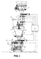
- FIG. 1 shows schematically an embodiment of a container scale, wherein a hopper 1 of a gravimetric metering device 20 is supported via at least one load cell 2, which is arranged here below a scaffold.
- the output of the load cell 2 is connected to a weighing electronics 3 with integrated metering control (see dash-dotted arrow), which registers, processes and displays the weight of the reservoir 1 and the weight running via the metering device 20 in a control computer.
- the dosing control also activates a lower flap 4 in a feed tube 1a, which merges into a tubular intermediate container 6, which is connected to a reservoir (silo) 7 provided above. Below the reservoir 7, an unspecified slide and an upper flap 5 is arranged, both of which are actuated by the weighing electronics 3 and dosing.
- the intermediate container 6 with the alternately operable flaps 4, 5 thus forms a so-called. Flap lock.
- an emptying flap 10 or a gate valve is provided below the hopper 1, which is also activated by the metering and is connected to a gravimetric metering device 20, in particular a Dosierrotorwaage, with pneumatic discharge.
- the hopper 1 the Dosierrotorwaage 20 is thus filled by a flap lock, which is formed from the two flaps 4 and 5 and the intermediate container 6 and operates as follows: First opens the upper flap 5 of the intermediate container 6. From the silo 7 flows (with open upper slide) Bulk material, such as coke dust in the intermediate container 6, which is located between the upper flap 5 and lower flap 4. In exchange, the displaced air is led into the silo 7.
- the upper Ba Schoichll flap 5 closes over time or by the signal of a level probe 8 of the intermediate container 6.
- the pressure in the coke-filled intermediate container 6 is detected by a pressure sensor 9, and the pressure signal to the weighing electronics 3 passed, so that the pressure on one in the Weighing electronics 3 integrated pressure control device is brought by supplying compressed air via a pump 16 on or slightly above the pressure of the reservoir 1 measured by a pressure sensor 29, which is formed in particular by the leakage air from a pneumatic conveyor line 11 during emptying of the metering device 20.
- the lower flap 4 opens on command from the weighing electronics 3.
- the coke dust is thus emptied via the filling tube 1a into the pre-container 1 located underneath.
- the lower flap 4 on the intermediate container 6 closes after a short time or empty message the level sensor 8 again.
- the transmitted from the hopper 1 air pressure in the intermediate container 6 is then possibly relaxed by opening a relief valve 12. This cycle is repeated at different time intervals, according to the Nachfrus the material and the required dosing of the dosing rotor balance 20 and the level specifications, determined from the respective weight of the reservoir. 1
- the coke dust then flows continuously into the feeder of the dosing rotor scale 20.
- the feeder or dosing rotor can pivot about the axis 18 under support or suspension on the load cell 2, thus providing a weighing signal.
- the pre-tank 1 has as well as the reservoir 7 optionally a ventilation device 13 for fluidizing the coke dust.
- a motor-driven, continuously operating stirring arm 1b is installed for additional support of the flow of material in the hopper 1.
- the level in the hopper 1 is thus detected gravimetrically by the measuring device and its filling by controlling the flap lock 4, 5 controlled accordingly.
- a pressure sensor 9 on the intermediate container 6 in order to detect the pressure prevailing therein and to equalize it with the pressure in the pre-container 1 detected via the pressure sensor 29.
- the pressure sensor 9, like the pressure sensor 29, is connected to the weighing electronics 3, in which a certain limit pressure value is determined and, depending on the required accuracy, is stored as a desired value, preferably a pressure difference of close to zero.
- another pressure sensor 19 can detect the pressure conditions on the pneumatic discharge device 11 in order to match the pressure signals with those of the pressure sensors 9 and 19 in the weighing electronics 3. Since a relatively high pressure in the intermediate container 6 can be achieved during the charging of powdery bulk materials, even at low flow rates, it is expedient to provide at least one venting device 12 there for faster pressure reduction, so that the desired limiting pressure value, in particular the complete pressure equalization as quickly as possible is reached. As a venting device 12, for example, a filter is used to prevent the escape of powder material. A similar pressure-release device 17 is also on the pre-tank. 1 provided, there to achieve a pressure reduction to approximate the surge tank pressure. In reverse, pressurization of the containers 1 and 6 can also take place via the compressed-air pump 16, in order to bring about the pressure equalization or the pressure equalization respectively before the lower flap 4 is opened.
- a negative pressure in the reservoir 1 can occur, for example, when the discharge device 11 is designed as a suction device. Again, a pressure equalization by the vent or pressurization of the reservoir 1 and the intermediate container 6 can be achieved before the opening of the lower flap 4 is carried out for bulk material transfer.
Landscapes
- Physics & Mathematics (AREA)
- General Physics & Mathematics (AREA)
- Weight Measurement For Supplying Or Discharging Of Specified Amounts Of Material (AREA)
- Basic Packing Technique (AREA)
- Filling Or Emptying Of Bunkers, Hoppers, And Tanks (AREA)
- Measuring Fluid Pressure (AREA)
- Medical Preparation Storing Or Oral Administration Devices (AREA)
- Road Paving Machines (AREA)
- Preliminary Treatment Of Fibers (AREA)
- Ship Loading And Unloading (AREA)
Description
- Die Erfindung betrifft ein Verfahren und eine Vorrichtung zum gravimetrischen Dosieren von Schüttgut mit den oberbegrifflichen Merkmalen des Patentanspruches 1 bzw. 4.
- Ein derartiges Verfahren und eine Vorrichtung zum Beschicken eines Behälters mit pulvrigen Gütern ist aus der
DE 34 13 757 A1 bekannt. Hierbei mündet in einem Vorbehälter wenigstens ein Zuführungsrohr, durch das pulverförmiges Schüttgut aus einem oder mehreren Vorratsbehältern nacheinander gesaugt wird, dort additiv verwogen und nach öffnen eines Bodenverschlusses einer Mischeinrichtung zugeführt wird. Derartige Gemengeanlagen zum Dosieren von Chargen pulvriger Güter werden beispielsweise in der keramischen Industrie verwendet, wobei mehrere Sorten unterschiedlicher Bindemittel, Füllstoffe, Farben, Zuschläge verwogen werden. Die Schüttgüter werden über Förderschnecken oder einen pneumatischen Förderstrom dem gemeinsamen Wägebehälter zugeführt. Bei derartigen Wägevorrichtungen, die in einem pneumatischen Förderstrom liegen, ist die Wiegegenauigkeit jedoch wesentlich von den Druckverhältnissen abhängig. So soll für eine ausreichende Wägegenauigkeit vermieden werden, daß im Förderstrom auftretende Druckstöße, z. B. aufgrund der Ventilbetätigungen sich auf die Waage auswirken. Häufig werden hierzu die ein- und ausmündenden Leitungen zum Beschicken und Austragen im Anschlußbereich horizontal verlaufend geführt, damit Druckänderungen keinen Einfluß auf die Wägezellen des Vorbehälters ausüben. Diese Maßnahmen reichen jedoch nicht aus, um einen Einfluß der Druckverhältnisse auf das Wägesignal auszuschließen, so daß bereits bei geringen Druckunterschieden oder undefinierten Leckluftmengen die Wägeergebnisse verfälscht werden können. - Aus der
DE 33 10 735 A1 ist desweiteren ein Justierverfahren für einen Wägebehälter bekannt, wobei die Wirkung von Kraftnebenschlüssen auf das Auswägeergebnis dadurch minimiert werden soll, daß aus der scheinbaren Belastungs- bzw. Gewichtsänderung des Wägebehälters in Abhängigkeit von der Temperatur oder dem Druck eine Korrekturgröße ermittelt wird, die dann dem Wägesignal durch Addition oder Subtraktion überlagert wird. Da hierbei direkt in das Wägesignal eingegriffen wird, ist die Eichfähigkeit einer derartigen Gemengeanlage nicht gegeben. - Aus der
EP-B-0 644 406 der Anmelderin ist zudem die Anordnung eines Drucksensors zur Messung des Druckes im Wägebehälter bekannt, wobei die jeweils herrschenden Druckverhältnisse in dem Wägebehälter erfaßt werden können. Dabei wird erst bei Erreichen oder Unterschreiten eines bestimmten Grenzdruckwertes das Wägesignal der Wägezellen von der Wägeelektronik zur Registrierung übernommen. Hierdurch wird vermieden, daß eine Wägung bei zu hohem Unter- oder Überdruck erfolgt, die die Wägeergebnisse der geeichten Wägezelle und Wägeelektronik verfälschen könnten. Die Registrierung des Wägeergebnisses und Weiterschaltung des nächsten Dosierschrittes erfolgt solange nicht, bis der Druck im Wägebehälter mit dem Umgebungsdruck im wesentlichen übereinstimmt. Dieses System ist jedoch für die pneumatische Austragung, insbesondere bei geringen Förderströmen mit entsprechend geringen Luftmengen kaum geeignet. - Aus der
FR-A-26 31 443 - Demzufolge liegt der Erfindung die Aufgabe zugrunde, ein Verfahren zum gravimetrischen Dosieren von Schüttgut und eine dementsprechende Vorrichtung anzugeben, wobei eine höhere Wägegenauigkeit, insbesondere bei geringen Förderströmen erreicht wird.
- Diese Aufgabe wird gelöst durch ein Verfahren mit den Merkmalen des Anspruches 1 bzw. durch eine Vorrichtung mit den Merkmalen des Anspruches 4.
- In erfindungsgemäßer Ausführung wird noch vor dem Wäge- bzw. Vorbehälter zur gravimetrischen Dosiervorrichtung ein Zwischenbehälter mit Klappenschleuse dazu verwendet, die Schüttgutzuführung und Beschickung des Vorbehälters gezielt zu steuern. Damit wird erreicht, daß keine Leckluft aus dem pneumatischen Fördersystem entweichen kann, insbesondere nicht beim Start des Dosiervorganges. Durch diese Kompensation der Krafteinflüsse der von der gravimetrischen Dosiervorrichtung zu-und abführenden Leitungen ergibt sich insgesamt eine genauere Dosierung.
- Weitere vorteilhafte Ausgestaltungen sind Gegenstand der abhängigen Ansprüche.
- Nachfolgend wird ein Ausführungsbeispiel anhand der Zeichnung näher erläutert und beschrieben. Hierbei zeigt die (einzige) Fig. 1 schematisch ein Ausführungsbeispiel einer Behälterwaage, wobei sich ein Vorbehälter 1 einer gravimetrischen Dosiervorrichtung 20 über wenigstens eine Wägezelle 2 abstützt, die hier unterhalb eines Gerüstes angeordnet ist. Der Ausgang der Wägezelle 2 ist mit einer Wägeelektronik 3 mit integrierter Dosiersteuerung verbunden (vgl. strichpunktierter Pfeil), die das Gewicht des Vorbehälters 1 und das über die Dosiervorrichtung 20 laufende Gewicht in einem Steuerungsrechner registriert, verarbeitet und anzeigt. Die Dosiersteuerung aktiviert auch eine untere Klappe 4 in einem Zuführrohr 1a, das in einen rohrförmigen Zwischenbehälter 6 übergeht, der mit einem darüber vorgesehenen Vorratsbehälter (Silo) 7 verbunden ist. Unterhalb des Vorratsbehälters 7 ist ein nicht näher bezeichneter Schieber und eine obere Klappe 5 angeordnet, die beide von der Wägeelektronik 3 bzw. Dosiersteuerung betätigbar sind. Der Zwischenbehälter 6 mit den wechselweise betätigbaren Klappen 4, 5 bildet somit eine sog. Klappenschleuse.
- Unterhalb des Vorbehälters 1 ist eine Entleerungsklappe 10 oder ein Absperrschieber vorgesehen, die bzw. der ebenfalls von der Dosiersteuerung aktiviert wird und an eine gravimetrische Dosiervorrichtung 20, insbesondere eine Dosierrotorwaage, mit pneumatischer Austragung angeschlossen ist. Der Vorbehälter 1 der Dosierrotorwaage 20 wird somit durch eine Klappenschleuse befüllt, die aus den beiden Klappen 4 und 5 sowie dem Zwischenbehälter 6 gebildet ist und wie folgt arbeitet: Zunächst öffnet die obere Klappe 5 des Zwischenbehälters 6. Aus dem silo 7 fließt (bei geöffneten oberen Schieber) Schüttgut, z.B. Koksstaub in den Zwischenbehälter 6, der sich zwischen oberer Klappe 5 und unterer Klappe 4 befindet. Im Austausch dazu wird die verdrängte Luft in das Silo 7 geleitet. Die obere Bafüll-Klappe 5 schließt über Zeit oder durch das Signal einer Füllstandssonde 8 des Zwischenbehälters 6. Der Druck im mit Koks gefüllten Zwischenbehälter 6 wird von einem Drucksensor 9 erfaßt, und das Drucksignal zur Wägeelektronik 3 geleitet, damit der Druck über eine in die Wägeelektronik 3 integrierte Druckregeleinrichtung durch Zuführen von Druckluft über eine Pumpe 16 auf oder geringfügig über den von einem Drucksensor 29 gemessenen Druck des Vorbehälters 1 gebracht wird, der insbesondere durch die Leckluft von einer pneumatischen Förderleitung 11 beim Entleeren der Dosiervorrichtung 20 entsteht. Dann öffnet die untere Klappe 4 auf Befehl von der Wägeelektronik 3. Der Koksstaub wird somit über das Befüllrohr 1a in den darunter befindlichen Vorbehälter 1 entleert. Die untere Klappe 4 am Zwischenbehälter 6 schließt nach kurzer Zeit oder Leermeldung der Füllstandssonde 8 wieder. Der vom Vorbehälter 1 übertragene Luftdruck im Zwischenbehälter 6 wird dann ggf. durch öffnen eines Entlastungsventils 12 entspannt. Dieser Zyklus wiederholt sich in zeitlich unterschiedlichen Abständen, entsprechend dem Nachfließverhalten des Materials und der geforderten Dosierleistung der Dosierrotorwaage 20 und den Füllstandsvorgaben, ermittelt aus dem jeweiligen Gewicht des Vorbehälters 1.
- Aus dem Vorbehälter 1 fließt der Koksstaub dann kontinuierlich in das Zellenrad der Dosierrotorwaage 20. Wie oben angedeutet, kann sich das Zellenrad bzw. Dosierrotor um die Achse 18 unter Abstützung oder Aufhängung an der Wägezelle 2 verschwenken und liefert damit ein Wägesignal. Der Vorbehälter 1 besitzt ebenso wie der Vorratsbehälter 7 optional eine Belüftungseinrichtung 13 zur Fluidisierung des Koksstaubes. Zur zusätzlichen Unterstützung des Materialflusses ist in den Vorbehälter 1 ein motorisch angetriebener, kontinuierlich arbeitender Rührarm 1b eingebaut. Der Füllstand im Vorbehälter 1 wird somit von der Messeinrichtung gravimetrisch erfasst und seine Befüllung durch Ansteuerung der Klappenschleuse 4, 5 entsprechend geregelt.
- Wie oben angegeben, ist es wesentlich,an dem Zwischenbehälter 6 einen Drucksensor 9 anzuordnen, um den darin herrschenden Druck zu erfassen und mit dem über den Drucksensor 29 erfaßten Druck im Vorbehälter 1 abzugleichen. Der Drucksensor 9 ist ebenso wie der Drucksensor 29 an die Wägeelektronik 3 angeschlossen, in der ein bestimmter Grenzdruckwert festgelegt und je nach der geforderten Genauigkeit als Sollwert, bevorzugt einer DruckDifferenz von nahe Null, abgespeichert ist. Erst wenn der Drucksensor 9 des Zwischenbehälters 6 im Vergleich zum Druckwert des Drucksensors 29 am Vorbehälter 1 einen Druck erfaßt, der diesem Abgleich- oder Grenzdifferenzdruckwert, bevorzugt nahe Null entspricht, wird von der Wägeelektronik 3 das Signal zum Öffnen der unteren Klappe 4 abgegeben und so das Zudosieren einer weiteren Charge in den sich somit auf etwa gleichem Druckniveau befindlichen Vorbehälter 1 ausgelöst.
- Darüber hinaus kann ein weiterer Drucksensor 19 die Druckverhältnisse an der pneumatischen Austragvorrichtung 11 erfassen, um die Drucksignale mit denen der Drucksensoren 9 und 19 in der Wägeelektronik 3 miteinander abzugleichen. Da bei der Beschickung mit pulvrigen Schüttgütern, auch bei geringen Volumenströmen, ein relativ hoher Druck in dem Zwischenbehälter 6 erreicht werden kann, ist es zweckmäßig, dort wenigstens eine Entlüftungsvorrichtung 12 zum schnelleren Druckabbau vorzusehen, damit der angestrebte Grenzdruckwert, insbesondere die vollständige Druckausgleichung möglichst rasch erreicht wird. Als Entlüftungsvorrichtung 12 wird z.B. ein Filter verwendet, um das Austreten von Pulvermaterial zu vermeiden. Eine ähnliche Druck-Entspannungsvorrichtung 17 ist auch am Vorbehälter 1 vorgesehen, um auch dort einen Druckabbau zur Angleichung an den Zwischenbehälterdruck zu erreichen. In Umkehrung kann über die Druckluft-Pumpe 16 auch eine Druckbeaufschlagung der Behälter 1 bzw. 6 erfolgen, um dem Druckausgleich bzw. die DruckAngleichung jeweils vor Öffnen der unteren Klappe 4 herbeizuführen.
- Bei dieser Ausführung mit pneumatischer Fördervorrichtung 11 können durch die Kompensation der Druckverhältnisse in dem Vorbehälter 1 und dem Zwischenbehälter 6 mit Klappenschleuse 4, 5 über die Austragvorrichtung 11 keine Leckluft und Fehlströmungen mit Verfälschungen des Wägeergebnisses mehr auftreten. Aufgrund der Druckmessung mit den Drucksensoren 9 und 29 bzw. 19 läßt sich somit die Schüttgutförderung der Dosierrotorwaage 20 optimieren. Wenn beispielsweise im Vorbehälter 1 ein Überdruck herrscht, kann der Zwischenbehälter 6 über die Druckluft-Pumpe beaufschlagt werden, so daß sich eine Druckangleichung gegenüber dem Vorbehälter 1 ergibt. Durch diese Angleichung der Druckverhältnisse im Zwischenbehälter 6 und im Vorbehälter 1 läßt sich die Dosiergenauigkeit durch Vermeidung von Fehlströmungen und Partikel-Rückströmungen in der Dosiervorrichtung 20 erhöhen.
- Bei einem Unterdruck im Vorbehälter 1 gilt sinngemäß hierbei das umgekehrte Verhältnis. Ein Unterdruck im Vorbehälter 1 kann beispielsweise dann auftreten, wenn die Austragvorrichtung 11 als Absaugvorrichtung ausgebildet ist. Auch hier läßt sich ein Druckausgleich durch die Entlüftung bzw. Druckbeaufschlagung des Vorbehälters 1 bzw. des Zwischenbehälters 6 erzielen, bevor die Öffnung der unteren Klappe 4 zur Schüttgutweitergabe erfolgt.
Claims (5)
- Verfahren zum gravimetrischen Dosieren von Schüttgut, das aus einem Vorratsbehälter (7) einem Vorbehälter (1) zugeführt, dort unter Bestimmung eines Wägesignals zur Weiterleitung an eine Wägeelektronik (3) gewogen und dann aus dem Vorbehälter (1) zu einer gravimetrischen Dosiervorrichtung (20) abgeleitet wird, wobei das Schüttgut vor der Wägung Im Vorbehälter (1) in einem Zwischenbehälter (6) zwischengespeichert wird und erst bei Erreichen eines Abgleichdruckwertes zwischen dem Vorbehälter (1) und dem Zwischenbehälter (6) weitergegeben wird, dadurch gekennzeichnet, dass der Druck im Zwischenbehälter (6) und im Vorbehälter (1) mit je einem Drucksensor (9, 29) kontinuierlich gemessen wird, und der im Zwischenbehälter (6) und/oder Vorbehälter (1) gemessene Druck, insbesondere deren Differenzdruckwert, zur Steuerung einer Dosiervorrichtung (20) zu einer Dosiersteuerung bzw. Wägeelektronik (3) geführt wird, sowie bei einer bestimmten Druckanstiegsrate der Zwischenbehälter (6) und/oder der Vorbehälter (1) entlüftet wird.
- Verfahren nach Anspruch 1, dadurch gekennzeichnet, dass
der Abgleichdruckwert auf eine Druckdifferenz von annähernd Null festgelegt wird. - Verfahren nach Anspruch 1, dadurch gekennzeichnet, dass
der Zwischenbehälter (6) und/oder Vorbehälter (1) von einer Pumpe (16) mit Druck beaufschlagbar ist. - Vorrichtung zum gravimetrischen Dosieren von Schüttgut gemäß einem der Ansprüche 1 bis 3, mit einem Vorbehälter (1), der auf wenigstens eine an eine Wägeelektronik (3) angeschlossene Wägezelle (2) abgestützt ist und über flexible Verbindungen mit einer Schüttgutzuleitung und einer gravimetrischen Dosiervorrichtung (20) verbunden ist, wobei vor dem Vorbehälter (1) eine Klappenschleuse (4, 5) mit einem Zwischenbehälter (6) angeordnet ist, und mit einer Förderleitung (11) zum Entleeren der Dosiervorrichtung (20),
dadurch gekennzeichnet, dass
ein Drucksensor (19) vorhanden ist, der dazu eingerichtet ist, bei einer pneumatischen Beschickung/Ausbringung des Schüttgutes mit Unter- oder Überdruck zusätzlich den Druck in der Förderleitung (11) zu messen und dass die Wägeelektronik (3) dazu eingerichtet ist, zur Festlegung des Abgleichdruckwertes den gemessenen Druck mit dem Druck In dem Zwischenbehälter (6) zu vergleichen. - Vorrichtung nach Anspruch 4, dadurch gekennzeichnet, dass
am Zwischenbehälter (6) wenigstens eine Füllstandssonde (8) vorgesehen ist.
Applications Claiming Priority (3)
| Application Number | Priority Date | Filing Date | Title |
|---|---|---|---|
| DE10153425 | 2001-11-03 | ||
| DE10153425A DE10153425A1 (de) | 2001-11-03 | 2001-11-03 | Verfahren und Vorrichtung zum gravimetrischen Dosieren von Schüttgut |
| PCT/EP2002/012261 WO2003040666A1 (de) | 2001-11-03 | 2002-11-04 | VERFAHREN UND VORRICHTUNG ZUM GRAVIMETRISCHEN DOSIEREN VON SCHüTTGUT |
Publications (2)
| Publication Number | Publication Date |
|---|---|
| EP1444490A1 EP1444490A1 (de) | 2004-08-11 |
| EP1444490B1 true EP1444490B1 (de) | 2007-08-08 |
Family
ID=7704142
Family Applications (1)
| Application Number | Title | Priority Date | Filing Date |
|---|---|---|---|
| EP02787549A Expired - Lifetime EP1444490B1 (de) | 2001-11-03 | 2002-11-04 | Verfahren und vorrichtung zum gravimetrischen dosieren von schüttgut |
Country Status (17)
| Country | Link |
|---|---|
| US (1) | US7175048B2 (de) |
| EP (1) | EP1444490B1 (de) |
| JP (1) | JP4084304B2 (de) |
| KR (1) | KR100912758B1 (de) |
| CN (1) | CN1294408C (de) |
| AT (1) | ATE369544T1 (de) |
| AU (1) | AU2002351823B2 (de) |
| BR (1) | BR0213859B1 (de) |
| CA (1) | CA2469267C (de) |
| DE (2) | DE10153425A1 (de) |
| DK (1) | DK1444490T3 (de) |
| EA (1) | EA005447B1 (de) |
| ES (1) | ES2291522T3 (de) |
| MX (1) | MXPA04004207A (de) |
| PL (1) | PL206410B1 (de) |
| UA (1) | UA77219C2 (de) |
| WO (1) | WO2003040666A1 (de) |
Families Citing this family (27)
| Publication number | Priority date | Publication date | Assignee | Title |
|---|---|---|---|---|
| US6722294B2 (en) * | 2002-08-06 | 2004-04-20 | Vitro Global, S.A. | Method and apparatus for feeding a pulverized material |
| AT503853B1 (de) * | 2003-05-12 | 2008-01-15 | Steinwald Kurt | Vorrichtung zum dosieren pulverförmiger materialien |
| DE20312073U1 (de) * | 2003-08-05 | 2004-12-23 | Volkmann Gmbh | Vakuumfördervorrichtung mit Wäge- oder Dosiereinrichtung |
| CA2567603C (en) * | 2004-06-23 | 2013-06-11 | Ecolab Inc. | Method for multiple dosage of liquid products, dosing apparatus and dosing system |
| US7270249B1 (en) * | 2005-03-03 | 2007-09-18 | Burkhead Ronnie J | Pneumatic metering apparatus for flowable solids product |
| DE102006041298A1 (de) * | 2006-09-01 | 2008-03-20 | Bühler AG | Mikrodosiereinrichtung |
| DE502007004990D1 (de) * | 2007-02-13 | 2010-10-21 | Mettler Toledo Ag | Dosiervorrichtung mit einer Aufnahmevorrichtung für eine einsetzbare Einheit |
| EP2205532A1 (de) * | 2007-10-04 | 2010-07-14 | Vitro Global, S.A. | Verfahren und vorrichtung zum zuführen eines pulverisierten materials |
| CN101514918B (zh) * | 2008-02-21 | 2012-03-28 | 上海国强生化工程装备有限公司 | 一种补料称重计量控制装置 |
| DE102008020218B3 (de) * | 2008-04-22 | 2009-11-19 | Azo Holding Gmbh | Verfahren und Vorrichtung zur Überführung von fließfähigem Schüttgut |
| WO2009143402A2 (en) * | 2008-05-23 | 2009-11-26 | Vexor Technology, Inc. | Method and apparatus to deliver solid fuel to a combustion zone |
| USRE48951E1 (en) | 2015-08-05 | 2022-03-01 | Ecolab Usa Inc. | Hand hygiene compliance monitoring |
| US9102509B2 (en) | 2009-09-25 | 2015-08-11 | Ecolab Inc. | Make-up dispense in a mass based dispensing system |
| US9051163B2 (en) * | 2009-10-06 | 2015-06-09 | Ecolab Inc. | Automatic calibration of chemical product dispense systems |
| US8511512B2 (en) * | 2010-01-07 | 2013-08-20 | Ecolab Usa Inc. | Impact load protection for mass-based product dispensers |
| CN102788658B (zh) * | 2012-07-24 | 2014-04-30 | 东北大学 | 一种用于量筒散粒体底部压力测试的室内实验装置及方法 |
| DE102012224054A1 (de) * | 2012-12-20 | 2014-06-26 | Henkel Ag & Co. Kgaa | Vorrichtung zum Befördern eines Betriebsstoffes |
| WO2015109298A1 (en) * | 2014-01-20 | 2015-07-23 | Johnson Matthey Process Technologies, Inc. | System and process for adding material to one or more units |
| GB2520191B (en) | 2014-09-24 | 2015-10-07 | Lpw Technology Ltd | A powder container comprising a pressure vessel and a pilot line |
| RU2620905C1 (ru) * | 2016-05-31 | 2017-05-30 | Федеральное государственное бюджетное образовательное учреждение высшего образования "Санкт-Петербургский государственный технологический институт (технический университет)" | Способ автоматического дозирования сыпучих материалов и устройство для его осуществления |
| WO2018019932A1 (de) * | 2016-07-27 | 2018-02-01 | Bühler AG | Dosier- und wiegevorrichtung und verfahren zur bestimmung des gewichts eines produktes in einer dosier- und wiegevorrichtung |
| WO2018165107A1 (en) | 2017-03-07 | 2018-09-13 | Ecolab Usa Inc. | Monitoring modules for hand hygiene dispensers |
| WO2018164064A1 (ja) * | 2017-03-10 | 2018-09-13 | 株式会社サタケ | 流量測定装置及び流量測定方法 |
| CN107117401A (zh) * | 2017-06-12 | 2017-09-01 | 合肥固泰自动化有限公司 | 一种基于稳流搅拌仓的定量喷煤粉系统 |
| US10529219B2 (en) | 2017-11-10 | 2020-01-07 | Ecolab Usa Inc. | Hand hygiene compliance monitoring |
| WO2020132525A1 (en) | 2018-12-20 | 2020-06-25 | Ecolab Usa Inc. | Adaptive route, bi-directional network communication |
| CN114275554B (zh) * | 2021-12-07 | 2024-05-14 | 内蒙古益婴美乳业有限公司 | 一种混粉加工用定量投料装置 |
Family Cites Families (19)
| Publication number | Priority date | Publication date | Assignee | Title |
|---|---|---|---|---|
| US3228563A (en) * | 1962-04-03 | 1966-01-11 | Stanley L Rankin | Device with positive displacement valve unit |
| US3677540A (en) * | 1969-04-21 | 1972-07-18 | Ambac Ind | Material discharge control apparatus |
| LU66430A1 (de) * | 1972-11-08 | 1973-02-05 | ||
| JPS5373168A (en) * | 1976-12-13 | 1978-06-29 | Hokushin Gohan Kk | Measuring method and apparatus for weight of powdered articles in wind sending process |
| DE2805565B1 (de) * | 1978-02-10 | 1979-06-07 | Gattys Verfahrenstech | Dosiereinrichtung fuer Schuettgueter bei pneumatischen Foerderanlagen |
| US4427133A (en) * | 1980-01-23 | 1984-01-24 | Halliburton Company | Additive material metering system with weighing means |
| FR2511149A1 (fr) * | 1981-08-04 | 1983-02-11 | Roussel Uclaf | Dispositif et procede de dosage de quantites predeterminees d'au moins un produit |
| DE3310735A1 (de) | 1983-03-24 | 1984-09-27 | Carl Schenck Ag, 6100 Darmstadt | Justierverfahren fuer eine waegevorrichtung und dazu geeignete vorrichtung |
| DE3413757A1 (de) * | 1984-04-12 | 1985-10-24 | Kurt F. 8942 Ottobeuren Lipfert | Verfahren und vorrichtung zum beschicken eines behaelters mit pulvrigen guetern |
| LU85811A1 (fr) * | 1985-03-15 | 1986-10-06 | Wurth Paul Sa | Installation de chargement d'un four a cuve |
| CH668641A5 (de) * | 1985-04-04 | 1989-01-13 | Buehler Ag Geb | Verfahren und vorrichtung zur automatischen erfassung des durchsatzes eines schuettgutstromes, z.b. getreide. |
| FR2631443A1 (fr) | 1988-05-16 | 1989-11-17 | Hasler Freres Int Sa | Procede de dosage de produits et dispositif pour la mise en oeuvre de ce procede |
| EP0606608B1 (de) * | 1993-01-13 | 1998-02-25 | Paul Wurth S.A. | Verfahren zum Evakuieren von festen Abfällen aus einer Gasreinigungsvorrichtung |
| DE4332030A1 (de) * | 1993-09-21 | 1995-03-23 | Pfister Gmbh | Verfahren und Vorrichtung zum gravimetrischen Dosieren von Schüttgütern |
| US5450984A (en) * | 1994-04-29 | 1995-09-19 | K-Tron Technologies, Inc. | Material feeding apparatus |
| CN2295998Y (zh) * | 1997-03-07 | 1998-10-28 | 江阴市华夏包装机械有限公司 | 粉粒包装机自动称重式计量装置 |
| CN2362110Y (zh) * | 1999-01-05 | 2000-02-02 | 侯瑞恒 | 一种定量秤 |
| US6121556A (en) * | 1999-01-26 | 2000-09-19 | Cole; Brand D. | Granular material weighing system |
| CN2524228Y (zh) * | 2002-01-18 | 2002-12-04 | 苑志超 | 打包机专用复合式计量秤 |
-
2001
- 2001-11-03 DE DE10153425A patent/DE10153425A1/de not_active Withdrawn
-
2002
- 2002-04-11 UA UA20040604236A patent/UA77219C2/uk unknown
- 2002-11-04 DE DE50210661T patent/DE50210661D1/de not_active Expired - Lifetime
- 2002-11-04 BR BRPI0213859-0A patent/BR0213859B1/pt active IP Right Grant
- 2002-11-04 AT AT02787549T patent/ATE369544T1/de not_active IP Right Cessation
- 2002-11-04 MX MXPA04004207A patent/MXPA04004207A/es active IP Right Grant
- 2002-11-04 ES ES02787549T patent/ES2291522T3/es not_active Expired - Lifetime
- 2002-11-04 AU AU2002351823A patent/AU2002351823B2/en not_active Expired
- 2002-11-04 CA CA2469267A patent/CA2469267C/en not_active Expired - Lifetime
- 2002-11-04 DK DK02787549T patent/DK1444490T3/da active
- 2002-11-04 JP JP2003542873A patent/JP4084304B2/ja not_active Expired - Lifetime
- 2002-11-04 PL PL370688A patent/PL206410B1/pl unknown
- 2002-11-04 KR KR1020047006707A patent/KR100912758B1/ko not_active Expired - Lifetime
- 2002-11-04 US US10/494,386 patent/US7175048B2/en not_active Expired - Lifetime
- 2002-11-04 CN CNB028222261A patent/CN1294408C/zh not_active Expired - Lifetime
- 2002-11-04 WO PCT/EP2002/012261 patent/WO2003040666A1/de not_active Ceased
- 2002-11-04 EA EA200400626A patent/EA005447B1/ru not_active IP Right Cessation
- 2002-11-04 EP EP02787549A patent/EP1444490B1/de not_active Expired - Lifetime
Also Published As
| Publication number | Publication date |
|---|---|
| PL370688A1 (en) | 2005-05-30 |
| WO2003040666A1 (de) | 2003-05-15 |
| ES2291522T3 (es) | 2008-03-01 |
| CN1585891A (zh) | 2005-02-23 |
| AU2002351823B2 (en) | 2008-04-10 |
| JP4084304B2 (ja) | 2008-04-30 |
| KR20050043738A (ko) | 2005-05-11 |
| EP1444490A1 (de) | 2004-08-11 |
| US7175048B2 (en) | 2007-02-13 |
| CA2469267A1 (en) | 2003-05-15 |
| CA2469267C (en) | 2012-09-11 |
| EA005447B1 (ru) | 2005-02-24 |
| JP2005509151A (ja) | 2005-04-07 |
| EA200400626A1 (ru) | 2004-10-28 |
| UA77219C2 (en) | 2006-11-15 |
| DE10153425A1 (de) | 2003-05-15 |
| DE50210661D1 (de) | 2007-09-20 |
| BR0213859A (pt) | 2004-08-31 |
| ATE369544T1 (de) | 2007-08-15 |
| MXPA04004207A (es) | 2004-09-13 |
| US20050145420A1 (en) | 2005-07-07 |
| KR100912758B1 (ko) | 2009-08-18 |
| BR0213859B1 (pt) | 2014-12-23 |
| PL206410B1 (pl) | 2010-08-31 |
| CN1294408C (zh) | 2007-01-10 |
| DK1444490T3 (da) | 2007-12-27 |
Similar Documents
| Publication | Publication Date | Title |
|---|---|---|
| EP1444490B1 (de) | Verfahren und vorrichtung zum gravimetrischen dosieren von schüttgut | |
| EP0644406B1 (de) | Gravimetrische Schüttgutdosierung mit Messung ab einem Grenzdruck | |
| DE10039564A1 (de) | Vorrichtung zum Fördern von Schüttgut | |
| DE19542651C1 (de) | Vorrichtung zur Überprüfung der Dichtigkeit von Schlauchbeutelpackungen | |
| DE2461093A1 (de) | Verfahren und vorrichtung zur regelung des gewichtsdurchsatzes von pulverfoermigem material | |
| DE1474594B2 (de) | Verfahren und Vorrichtung zum kon~ tinuierlichen, gravimetrischen Austragen eines Gutes aus einem Gutsbehälter | |
| CN110182608A (zh) | 一种计量装置及计量方法 | |
| WO1986004417A1 (fr) | Procede et dispositif de determination de valeurs caracteristiques, en particulier de cereales | |
| EP0468399B1 (de) | Anlage zum kontinuierlichen, pneumatischen gravimetrischen Dosieren und/oder Mischen von Schüttgütern | |
| CN209727227U (zh) | 一种计量装置 | |
| EP0246568B1 (de) | Waage für die Massendurchsatzerfassung im Einlauf eines Extruders | |
| EP1467190A2 (de) | Vorrichtung zum kontinuierlichen Dosieren und pneumatischen Fördern von schüttfähigen Gütern | |
| EP2185902B1 (de) | Kalibrierung von staubmassenstrommess-systemen | |
| EP4180777B1 (de) | Wäge- und fördereinrichtung und verfahren zur förderung und massendurchsatzerfassung von schüttgut | |
| DE2703736A1 (de) | Pneumatische foerdervorrichtung | |
| CN113797788B (zh) | 用于运行设备的混合装置的方法和系统 | |
| DE2925510A1 (de) | Verfahren und vorrichtung zur messung der foerderstaerke in einer pneumatischen foerderanlage | |
| DE3320477A1 (de) | Dosiereinrichtung fuer staubfoermiges schuettgut | |
| DE19514377A1 (de) | Verfahren und Anlage zum pneumatischen Fördern pulverförmiger oder körniger Materialien | |
| DE3514910C1 (de) | Verfahren zum Feststellen einer Nullpunktabweichung bei einer gravimetrischen Dosiervorrichtung | |
| DE2304310A1 (de) | Vorrichtung zum fuellen und gleichzeitigen wiegen von saecken, insbesondere ventilsaecken mit pulverfoermigem, griessigem oder koernigem fuellgut | |
| WO2026021922A1 (de) | Verfahren und vorrichtung zum diskontinuierlichen gravimetrischen dosieren von schüttgut | |
| DE1474594C (de) | Verfahren und Vorrichtung zum Kon tinuierhchen, gravimetnschen Austragen eines Gutes aus einem Gutsbehalter | |
| DE2641591A1 (de) | Dosierbandwaage | |
| DE7442886U (de) | Vorrichtung zur Regelung des Gewichtsdurchsatzes von pulverförmigem Material in einer pneumatischen Fördervorrichtung |
Legal Events
| Date | Code | Title | Description |
|---|---|---|---|
| PUAI | Public reference made under article 153(3) epc to a published international application that has entered the european phase |
Free format text: ORIGINAL CODE: 0009012 |
|
| 17P | Request for examination filed |
Effective date: 20040602 |
|
| AK | Designated contracting states |
Kind code of ref document: A1 Designated state(s): AT BE BG CH CY CZ DE DK EE ES FI FR GB GR IE IT LI LU MC NL PT SE SK TR |
|
| AX | Request for extension of the european patent |
Extension state: AL LT LV MK RO SI |
|
| 17Q | First examination report despatched |
Effective date: 20040930 |
|
| 17Q | First examination report despatched |
Effective date: 20040930 |
|
| GRAP | Despatch of communication of intention to grant a patent |
Free format text: ORIGINAL CODE: EPIDOSNIGR1 |
|
| GRAS | Grant fee paid |
Free format text: ORIGINAL CODE: EPIDOSNIGR3 |
|
| GRAA | (expected) grant |
Free format text: ORIGINAL CODE: 0009210 |
|
| AK | Designated contracting states |
Kind code of ref document: B1 Designated state(s): AT BE BG CH CY CZ DE DK EE ES FI FR GB GR IE IT LI LU MC NL PT SE SK TR |
|
| REG | Reference to a national code |
Ref country code: GB Ref legal event code: FG4D Free format text: NOT ENGLISH |
|
| REG | Reference to a national code |
Ref country code: CH Ref legal event code: EP |
|
| GBT | Gb: translation of ep patent filed (gb section 77(6)(a)/1977) |
Effective date: 20070815 |
|
| REG | Reference to a national code |
Ref country code: IE Ref legal event code: FG4D Free format text: LANGUAGE OF EP DOCUMENT: GERMAN |
|
| REF | Corresponds to: |
Ref document number: 50210661 Country of ref document: DE Date of ref document: 20070920 Kind code of ref document: P |
|
| REG | Reference to a national code |
Ref country code: DK Ref legal event code: T3 |
|
| ET | Fr: translation filed | ||
| PG25 | Lapsed in a contracting state [announced via postgrant information from national office to epo] |
Ref country code: BG Free format text: LAPSE BECAUSE OF FAILURE TO SUBMIT A TRANSLATION OF THE DESCRIPTION OR TO PAY THE FEE WITHIN THE PRESCRIBED TIME-LIMIT Effective date: 20071108 Ref country code: NL Free format text: LAPSE BECAUSE OF FAILURE TO SUBMIT A TRANSLATION OF THE DESCRIPTION OR TO PAY THE FEE WITHIN THE PRESCRIBED TIME-LIMIT Effective date: 20070808 Ref country code: FI Free format text: LAPSE BECAUSE OF FAILURE TO SUBMIT A TRANSLATION OF THE DESCRIPTION OR TO PAY THE FEE WITHIN THE PRESCRIBED TIME-LIMIT Effective date: 20070808 |
|
| NLV1 | Nl: lapsed or annulled due to failure to fulfill the requirements of art. 29p and 29m of the patents act | ||
| REG | Reference to a national code |
Ref country code: ES Ref legal event code: FG2A Ref document number: 2291522 Country of ref document: ES Kind code of ref document: T3 |
|
| PG25 | Lapsed in a contracting state [announced via postgrant information from national office to epo] |
Ref country code: GR Free format text: LAPSE BECAUSE OF FAILURE TO SUBMIT A TRANSLATION OF THE DESCRIPTION OR TO PAY THE FEE WITHIN THE PRESCRIBED TIME-LIMIT Effective date: 20071109 |
|
| PG25 | Lapsed in a contracting state [announced via postgrant information from national office to epo] |
Ref country code: SK Free format text: LAPSE BECAUSE OF FAILURE TO SUBMIT A TRANSLATION OF THE DESCRIPTION OR TO PAY THE FEE WITHIN THE PRESCRIBED TIME-LIMIT Effective date: 20070808 Ref country code: PT Free format text: LAPSE BECAUSE OF FAILURE TO SUBMIT A TRANSLATION OF THE DESCRIPTION OR TO PAY THE FEE WITHIN THE PRESCRIBED TIME-LIMIT Effective date: 20080108 |
|
| PLBE | No opposition filed within time limit |
Free format text: ORIGINAL CODE: 0009261 |
|
| STAA | Information on the status of an ep patent application or granted ep patent |
Free format text: STATUS: NO OPPOSITION FILED WITHIN TIME LIMIT |
|
| PG25 | Lapsed in a contracting state [announced via postgrant information from national office to epo] |
Ref country code: MC Free format text: LAPSE BECAUSE OF NON-PAYMENT OF DUE FEES Effective date: 20071130 Ref country code: SE Free format text: LAPSE BECAUSE OF FAILURE TO SUBMIT A TRANSLATION OF THE DESCRIPTION OR TO PAY THE FEE WITHIN THE PRESCRIBED TIME-LIMIT Effective date: 20071108 |
|
| 26N | No opposition filed |
Effective date: 20080509 |
|
| PG25 | Lapsed in a contracting state [announced via postgrant information from national office to epo] |
Ref country code: EE Free format text: LAPSE BECAUSE OF FAILURE TO SUBMIT A TRANSLATION OF THE DESCRIPTION OR TO PAY THE FEE WITHIN THE PRESCRIBED TIME-LIMIT Effective date: 20070808 |
|
| PG25 | Lapsed in a contracting state [announced via postgrant information from national office to epo] |
Ref country code: CY Free format text: LAPSE BECAUSE OF FAILURE TO SUBMIT A TRANSLATION OF THE DESCRIPTION OR TO PAY THE FEE WITHIN THE PRESCRIBED TIME-LIMIT Effective date: 20070808 |
|
| PG25 | Lapsed in a contracting state [announced via postgrant information from national office to epo] |
Ref country code: LU Free format text: LAPSE BECAUSE OF NON-PAYMENT OF DUE FEES Effective date: 20071104 |
|
| PGFP | Annual fee paid to national office [announced via postgrant information from national office to epo] |
Ref country code: AT Payment date: 20091120 Year of fee payment: 8 |
|
| PG25 | Lapsed in a contracting state [announced via postgrant information from national office to epo] |
Ref country code: IT Free format text: LAPSE BECAUSE OF NON-PAYMENT OF DUE FEES Effective date: 20071130 |
|
| REG | Reference to a national code |
Ref country code: CH Ref legal event code: PL |
|
| PG25 | Lapsed in a contracting state [announced via postgrant information from national office to epo] |
Ref country code: CH Free format text: LAPSE BECAUSE OF NON-PAYMENT OF DUE FEES Effective date: 20101130 Ref country code: LI Free format text: LAPSE BECAUSE OF NON-PAYMENT OF DUE FEES Effective date: 20101130 |
|
| PG25 | Lapsed in a contracting state [announced via postgrant information from national office to epo] |
Ref country code: AT Free format text: LAPSE BECAUSE OF NON-PAYMENT OF DUE FEES Effective date: 20101104 |
|
| REG | Reference to a national code |
Ref country code: CH Ref legal event code: AEN Free format text: DAS PATENT IST AUFGRUND DES WEITERBEHANDLUNGSANTRAGS VOM 28.08.2011 REAKTIVIERT WORDEN. |
|
| PGRI | Patent reinstated in contracting state [announced from national office to epo] |
Ref country code: CH Effective date: 20110906 |
|
| REG | Reference to a national code |
Ref country code: FR Ref legal event code: PLFP Year of fee payment: 14 |
|
| REG | Reference to a national code |
Ref country code: FR Ref legal event code: PLFP Year of fee payment: 15 |
|
| REG | Reference to a national code |
Ref country code: FR Ref legal event code: PLFP Year of fee payment: 16 |
|
| REG | Reference to a national code |
Ref country code: FR Ref legal event code: PLFP Year of fee payment: 17 |
|
| REG | Reference to a national code |
Ref country code: DE Ref legal event code: R082 Ref document number: 50210661 Country of ref document: DE Representative=s name: STOLMAR & PARTNER PATENTANWAELTE PARTG MBB, DE |
|
| PGFP | Annual fee paid to national office [announced via postgrant information from national office to epo] |
Ref country code: DK Payment date: 20211109 Year of fee payment: 20 Ref country code: ES Payment date: 20211207 Year of fee payment: 20 Ref country code: IE Payment date: 20211012 Year of fee payment: 20 Ref country code: GB Payment date: 20211007 Year of fee payment: 20 Ref country code: TR Payment date: 20211103 Year of fee payment: 20 Ref country code: CZ Payment date: 20211026 Year of fee payment: 20 Ref country code: DE Payment date: 20211005 Year of fee payment: 20 |
|
| PGFP | Annual fee paid to national office [announced via postgrant information from national office to epo] |
Ref country code: FR Payment date: 20211029 Year of fee payment: 20 Ref country code: CH Payment date: 20211014 Year of fee payment: 20 Ref country code: BE Payment date: 20211018 Year of fee payment: 20 |
|
| REG | Reference to a national code |
Ref country code: DE Ref legal event code: R071 Ref document number: 50210661 Country of ref document: DE |
|
| REG | Reference to a national code |
Ref country code: DK Ref legal event code: EUP Expiry date: 20221104 |
|
| REG | Reference to a national code |
Ref country code: CH Ref legal event code: PL |
|
| REG | Reference to a national code |
Ref country code: GB Ref legal event code: PE20 Expiry date: 20221103 |
|
| REG | Reference to a national code |
Ref country code: BE Ref legal event code: MK Effective date: 20221104 |
|
| REG | Reference to a national code |
Ref country code: IE Ref legal event code: MK9A |
|
| PG25 | Lapsed in a contracting state [announced via postgrant information from national office to epo] |
Ref country code: IE Free format text: LAPSE BECAUSE OF EXPIRATION OF PROTECTION Effective date: 20221104 Ref country code: GB Free format text: LAPSE BECAUSE OF EXPIRATION OF PROTECTION Effective date: 20221103 Ref country code: CZ Free format text: LAPSE BECAUSE OF EXPIRATION OF PROTECTION Effective date: 20221104 |
|
| REG | Reference to a national code |
Ref country code: ES Ref legal event code: FD2A Effective date: 20230503 |
|
| PG25 | Lapsed in a contracting state [announced via postgrant information from national office to epo] |
Ref country code: ES Free format text: LAPSE BECAUSE OF EXPIRATION OF PROTECTION Effective date: 20221105 |