EP1443619A1 - Abisolieren von Flachleitern - Google Patents
Abisolieren von Flachleitern Download PDFInfo
- Publication number
- EP1443619A1 EP1443619A1 EP03450029A EP03450029A EP1443619A1 EP 1443619 A1 EP1443619 A1 EP 1443619A1 EP 03450029 A EP03450029 A EP 03450029A EP 03450029 A EP03450029 A EP 03450029A EP 1443619 A1 EP1443619 A1 EP 1443619A1
- Authority
- EP
- European Patent Office
- Prior art keywords
- window
- ffc
- insulation
- laser
- roller
- Prior art date
- Legal status (The legal status is an assumption and is not a legal conclusion. Google has not performed a legal analysis and makes no representation as to the accuracy of the status listed.)
- Granted
Links
Images

Classifications
-
- H—ELECTRICITY
- H05—ELECTRIC TECHNIQUES NOT OTHERWISE PROVIDED FOR
- H05K—PRINTED CIRCUITS; CASINGS OR CONSTRUCTIONAL DETAILS OF ELECTRIC APPARATUS; MANUFACTURE OF ASSEMBLAGES OF ELECTRICAL COMPONENTS
- H05K3/00—Apparatus or processes for manufacturing printed circuits
- H05K3/22—Secondary treatment of printed circuits
- H05K3/28—Applying non-metallic protective coatings
- H05K3/288—Removal of non-metallic coatings, e.g. for repairing
-
- H—ELECTRICITY
- H02—GENERATION; CONVERSION OR DISTRIBUTION OF ELECTRIC POWER
- H02G—INSTALLATION OF ELECTRIC CABLES OR LINES, OR OF COMBINED OPTICAL AND ELECTRIC CABLES OR LINES
- H02G1/00—Methods or apparatus specially adapted for installing, maintaining, repairing or dismantling electric cables or lines
- H02G1/12—Methods or apparatus specially adapted for installing, maintaining, repairing or dismantling electric cables or lines for removing insulation or armouring from cables, e.g. from the end thereof
- H02G1/1275—Methods or apparatus specially adapted for installing, maintaining, repairing or dismantling electric cables or lines for removing insulation or armouring from cables, e.g. from the end thereof by applying heat
- H02G1/128—Methods or apparatus specially adapted for installing, maintaining, repairing or dismantling electric cables or lines for removing insulation or armouring from cables, e.g. from the end thereof by applying heat using radiant energy, e.g. a laser beam
-
- H—ELECTRICITY
- H02—GENERATION; CONVERSION OR DISTRIBUTION OF ELECTRIC POWER
- H02G—INSTALLATION OF ELECTRIC CABLES OR LINES, OR OF COMBINED OPTICAL AND ELECTRIC CABLES OR LINES
- H02G1/00—Methods or apparatus specially adapted for installing, maintaining, repairing or dismantling electric cables or lines
- H02G1/12—Methods or apparatus specially adapted for installing, maintaining, repairing or dismantling electric cables or lines for removing insulation or armouring from cables, e.g. from the end thereof
- H02G1/1295—Devices for splitting and dismantling flat cables
-
- H—ELECTRICITY
- H05—ELECTRIC TECHNIQUES NOT OTHERWISE PROVIDED FOR
- H05K—PRINTED CIRCUITS; CASINGS OR CONSTRUCTIONAL DETAILS OF ELECTRIC APPARATUS; MANUFACTURE OF ASSEMBLAGES OF ELECTRICAL COMPONENTS
- H05K1/00—Printed circuits
- H05K1/02—Details
- H05K1/03—Use of materials for the substrate
- H05K1/0393—Flexible materials
-
- H—ELECTRICITY
- H05—ELECTRIC TECHNIQUES NOT OTHERWISE PROVIDED FOR
- H05K—PRINTED CIRCUITS; CASINGS OR CONSTRUCTIONAL DETAILS OF ELECTRIC APPARATUS; MANUFACTURE OF ASSEMBLAGES OF ELECTRICAL COMPONENTS
- H05K2203/00—Indexing scheme relating to apparatus or processes for manufacturing printed circuits covered by H05K3/00
- H05K2203/01—Tools for processing; Objects used during processing
- H05K2203/0195—Tool for a process not provided for in H05K3/00, e.g. tool for handling objects using suction, for deforming objects, for applying local pressure
-
- H—ELECTRICITY
- H05—ELECTRIC TECHNIQUES NOT OTHERWISE PROVIDED FOR
- H05K—PRINTED CIRCUITS; CASINGS OR CONSTRUCTIONAL DETAILS OF ELECTRIC APPARATUS; MANUFACTURE OF ASSEMBLAGES OF ELECTRICAL COMPONENTS
- H05K3/00—Apparatus or processes for manufacturing printed circuits
- H05K3/0011—Working of insulating substrates or insulating layers
- H05K3/0017—Etching of the substrate by chemical or physical means
- H05K3/0026—Etching of the substrate by chemical or physical means by laser ablation
- H05K3/0032—Etching of the substrate by chemical or physical means by laser ablation of organic insulating material
-
- H—ELECTRICITY
- H05—ELECTRIC TECHNIQUES NOT OTHERWISE PROVIDED FOR
- H05K—PRINTED CIRCUITS; CASINGS OR CONSTRUCTIONAL DETAILS OF ELECTRIC APPARATUS; MANUFACTURE OF ASSEMBLAGES OF ELECTRICAL COMPONENTS
- H05K3/00—Apparatus or processes for manufacturing printed circuits
- H05K3/22—Secondary treatment of printed circuits
- H05K3/28—Applying non-metallic protective coatings
- H05K3/281—Applying non-metallic protective coatings by means of a preformed insulating foil
Definitions
- the invention relates to the stripping of flat conductors using a laser.
- Flat conductor, so-called FFCs are used in particular in the automotive industry for the production of Wire harnesses, increasingly used because they are unlike round conductors by machines can be manipulated and therefore particularly in the manufacture of wiring harnesses for motor vehicles, but also for other industrial applications, cheaper are as round leaders.
- the laminated FFCs consist of electrical conductor tracks, mostly made of copper, which are glued parallel to each other between two foils and so to the outside and with each other are isolated.
- the films can be multi-layered or more than two foils can be used.
- extruded FFCs consist of conductor tracks that are passed through special extrusion machines are guided, an electrically insulating extrudate being poured around them or is injected so that the individual conductor tracks through the extrudate to the outside and against each other are isolated.
- the present invention relates to both types of FFCs.
- the cross sections of the actual conductor tracks can be round, oval, rectangular or be provided with another shape.
- FFCs of whatever kind, enables branches or Establish connections in such a way that the FFCs to be connected to the desired ones If the insulation material is removed, they say: "Windows will be created", and the FFCs are suitably overlaid with their windows. The now exposed and are located at a close distance from one another or are already touching one another Conductors are interconnected e.g. connected by soldering, welding, etc. and the Insulation to the outside is usually secured again using adhesive, adhesive films or the like.
- each FFC it may also be necessary to strip the end of each FFC to be able to apply plugs, contacts or the like.
- the invention aims to provide a method that the disadvantages mentioned does not have, but the manufacture of windows in FFCs on reliable and to the to achieve entire manufacturing process in a customized manner, with a subsequent Treatment of the surfaces of the conductor tracks can be dispensed with and with the FFCs provided with windows are either processed immediately or a station are supplied in which the surfaces of the exposed conductor track sections to be coated appropriately in order to be electrically perfect conductive surface that can be reliably soldered or welded to create, on which the FFCs thus finished can be stored in any way.
- these goals are achieved in that the laser used to create the windows, preferably a CO 2 laser, processes only the edge region of the insulation window and in a subsequent step the insulation residues in the middle of the window are removed.
- a brush moved with respect to the FFC e.g. rotating brush
- the axis of rotation of the brush parallel to the axis of the Role e.g. rotating brush
- the direction of rotation of the brush should preferably be against the feed movement the FFC must be on the contact radius.
- Another advantage of the method according to the invention is the reduction in processing time, since only the border of the insulation window is scanned with the laser must and not the entire area of the insulation window and since the rest of the insulation is stripped by the knife quickly and almost regardless of the size of the window.
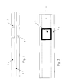
- the edge region 3 of a window 2 to be formed in the FFC 1 is produced in a manner known per se by means of a laser, preferably a CO 2 laser.
- the entire insulation material 4 is removed by means of which the actual conductor 5, which is usually made of copper or a copper alloy, is electrically insulated, and this on both sides of the FFC 1.
- a residual region of the insulation material 4 is indicated in the region of the frame 3.
- the FFC 1 is carried out taut Shape led lengthways over a roller 6, the diameter of which is preferably a maximum is 5 to 60 times the thickness of the FFC.
- a wedge or Knife 7 In the area where the boundary layer are already curved between insulation material 4 and conductor 5, a wedge or Knife 7, its width (that is its extension transverse to the longitudinal axis of the FFC and parallel to the axis of curvature of the roller 6) is at least substantially equal to the width of the Window 2, but in no case is greater than the outer width of the window frame 3, with the Cut ahead into the border area between the insulation material 4 and the conductor 5 brought and causes the further movement of the FFC 1 in the direction of arrow 9 that Insulation material in the area of the window 2 is peeled off properly, which the bare surface of the Head 5 is exposed in the area of the window 2.
- FIGS. 1 and 3 Since it is necessary in most applications, the conductor 5 in the area of the window To expose 2 on both sides, this is shown in FIGS. 1 and 3, the removal of the Insulation material on the inner side of the window 2 in FIG. 3 takes place entirely analogous to the illustrated distance of the outer area, either in a subsequent one Processing station in the case of continuous operation or by renewed Run through the workstation shown with the FFC reversed at step by step Production.
- the FFC 1 has a single conductor 5, of course this is not the case in most practical applications, but rather the FFC has several conductors lying next to one another and electrically insulated from one another , of which usually only a few are made accessible through windows should. This change in geometry or dimensions changes, however nothing at all to carry out the method according to the invention.
- the knife 7 is shown in FIG. 3 as a simple rectilinear wedge-shaped instrument, Of course, depending on the geometric conditions, the shape can of the knife 7 deviate from the shape shown. 3 is also shown simple tilting movement of the knife 7 about the axis 10 in the direction of the arrow 11 or in The opposite direction is not absolutely necessary, it is also a linear or a combined one Rotation and sliding movement possible when delivering or removing the knife 7.
- roller 6 a fixed, rounded edge can be used instead of the roller 6, over which the FFC 1 is pulled.
- the advantage of using roller 6 is that that the friction at normal feed and thus the elongation of the FFC is essential is reduced, the roller being synchronized with the feed movement during the peeling process 9 of the FFC can be driven to achieve the most precise positioning possible and ensure leadership.
- the surface of the roller can be designed in this way be that it has a high friction compared to the insulation material of the FFC 1 and in this way supports the positioning as best as possible.
- a fixed, rounded, edge as smooth as possible, low friction Surface with regard to the material of the FFC is a basic condition.
Abstract
Description
Claims (7)
- Verfahren zum Abisolieren eines Bereiches, eines sogenannten Fensters, eines Flachleiters, eines sogenannten FFC, mittels Laser, dadurch gekennzeichnet, dass der zur Schaffung des Fenster eingesetzte Laser, bevorzugt ein CO2-Laser, nur den Randbereich des Fensters bearbeitet, und dass in einem nachfolgenden Schritt die Isolationsreste im Fensterinneren entfernt werden.
- Verfahren nach Anspruch 1, dadurch gekennzeichnet, dass die Isolationsreste im Fensterinneren mittels mechanischer, thermischer oder anderer physikalischen Verfahren entfernt werden.
- Verfahren nach Anspruch 2, dadurch gekennzeichnet, dass der FFC über eine Rolle (6) mit kleinen Durchmesser, bevorzugt zwischen dem 5-fachen und dem 60-fachen der Stärke des FFC, abgerollt wird, und dass an der Oberfläche des FFC ein Keil (7) nach Art eines Rakelmessers in den vom Laser freigelegten Randbereich des Fensters eingreift und die Isolierung (4) wegschiebt bzw. anhebt und damit entfernt.
- Verfahren nach Anspruch 3, dadurch gekennzeichnet, dass der Keil (7) um eine Achse (10), die zur Achse der Rolle (6) parallel verläuft, schwenkbar ist.
- Verfahren nach Anspruch 2, dadurch gekennzeichnet, dass der FFC über eine Rolle (6) mit kleinen Durchmesser, bevorzugt zwischen dem 5-fachen und dem 60-fachen der Stärke des FFC, abgerollt wird, und dass an der Oberfläche des FFC eine Bürste in den vom Laser freigelegten Randbereich des Fensters eingreift und die Isolierung (4) wegschiebt bzw. anhebt und damit entfernt.
- Verfahren nach Anspruch 5, dadurch gekennzeichnet, dass die Bürste um eine Achse, die zur Achse der Rolle (6) parallel verläuft, drehbar ist.
- Verfahren nach Anspruch 6, dadurch gekennzeichnet, dass die Drehrichtung der Bürste im Kontaktbereich mit dem FFC der Vorschubbewegung des FFC entgegengesetzt ist.
Priority Applications (5)
| Application Number | Priority Date | Filing Date | Title |
|---|---|---|---|
| DE50303808T DE50303808D1 (de) | 2003-01-29 | 2003-01-29 | Abisolieren von Flachleitern |
| AT03450029T ATE330351T1 (de) | 2003-01-29 | 2003-01-29 | Abisolieren von flachleitern |
| EP03450029A EP1443619B1 (de) | 2003-01-29 | 2003-01-29 | Abisolieren von Flachleitern |
| US10/767,153 US7026572B2 (en) | 2003-01-29 | 2004-01-29 | Stripping insulation from flat cables |
| JP2004021096A JP2004343986A (ja) | 2003-01-29 | 2004-01-29 | 平形導線のストリッピング |
Applications Claiming Priority (1)
| Application Number | Priority Date | Filing Date | Title |
|---|---|---|---|
| EP03450029A EP1443619B1 (de) | 2003-01-29 | 2003-01-29 | Abisolieren von Flachleitern |
Publications (2)
| Publication Number | Publication Date |
|---|---|
| EP1443619A1 true EP1443619A1 (de) | 2004-08-04 |
| EP1443619B1 EP1443619B1 (de) | 2006-06-14 |
Family
ID=32605521
Family Applications (1)
| Application Number | Title | Priority Date | Filing Date |
|---|---|---|---|
| EP03450029A Expired - Lifetime EP1443619B1 (de) | 2003-01-29 | 2003-01-29 | Abisolieren von Flachleitern |
Country Status (5)
| Country | Link |
|---|---|
| US (1) | US7026572B2 (de) |
| EP (1) | EP1443619B1 (de) |
| JP (1) | JP2004343986A (de) |
| AT (1) | ATE330351T1 (de) |
| DE (1) | DE50303808D1 (de) |
Cited By (5)
| Publication number | Priority date | Publication date | Assignee | Title |
|---|---|---|---|---|
| DE102005004754A1 (de) * | 2005-02-02 | 2006-08-10 | Lisa Dräxlmaier GmbH | Verfahren zur Nachreinigung von abisolierten Bereichen einer elektrischen Leitung |
| DE102005021495A1 (de) * | 2005-05-10 | 2006-11-16 | Robert Bosch Gmbh | Verfahren zum lokalen Entfernen einer Abdeckmasse von einer Oberfläche sowie Vorrichtung zum Durchführen eines solchen Verfahrens |
| DE102005023063A1 (de) * | 2005-05-19 | 2006-11-23 | Lisa Dräxlmaier GmbH | Verfahren und Vorrichtung zum Abisolieren eines Flachbandkabels |
| DE102020211706A1 (de) | 2020-09-18 | 2021-09-16 | Wafios Aktiengesellschaft | Verfahren und Drahtverarbeitungsmaschine zur Herstellung von Formteilen aus isoliertem Flachmaterial |
| DE102021201275A1 (de) | 2021-02-10 | 2022-08-11 | Wafios Aktiengesellschaft | Verfahren und Drahtverarbeitungsmaschine zur Herstellung von Formteilen aus isoliertem Flachmaterial |
Families Citing this family (7)
| Publication number | Priority date | Publication date | Assignee | Title |
|---|---|---|---|---|
| DK1928423T3 (en) * | 2005-09-14 | 2016-02-29 | Mannkind Corp | A method for drug formulation based on increasing the affinity of the active substances to the crystalline microparticle surfaces |
| US20070193985A1 (en) * | 2006-02-20 | 2007-08-23 | Howard Patrick C | Method for removing a coating from a substrate using a defocused laser beam |
| KR101907484B1 (ko) * | 2011-07-21 | 2018-12-05 | 미래나노텍(주) | 터치 스크린 패널 제조 장치 및 제조 방법 |
| EP2747225B1 (de) | 2012-12-20 | 2017-10-04 | Schleuniger Holding AG | Verfahren und Vorrichtung zur Beseitigung einer Abschirmung von einem Kabel |
| RS61248B1 (sr) | 2016-10-18 | 2021-01-29 | Komax Holding Ag | Postupak i uređaj za skidanje izolacije kabla sa višeslojnom oblogom |
| JP7226111B2 (ja) * | 2019-05-31 | 2023-02-21 | 株式会社オートネットワーク技術研究所 | 配線部材 |
| CN113210864B (zh) * | 2021-05-28 | 2023-04-18 | 东风柳州汽车有限公司 | 一种汽车天窗加强框激光拼焊坯料及制造方法 |
Citations (5)
| Publication number | Priority date | Publication date | Assignee | Title |
|---|---|---|---|---|
| JPH01136396A (ja) * | 1987-11-20 | 1989-05-29 | Fujitsu Ltd | ワイアボンダ |
| US4931616A (en) * | 1988-01-25 | 1990-06-05 | Mitsubishi Denki Kabushiki Kaisha | Method for removing insulating coating of electric cable and apparatus therefor |
| JPH0433510A (ja) * | 1990-05-30 | 1992-02-04 | Mitsubishi Electric Corp | レーザ光による電線被覆剥離装置 |
| JP2002027626A (ja) * | 2000-07-03 | 2002-01-25 | Auto Network Gijutsu Kenkyusho:Kk | Ffcの絶縁被膜の剥離 |
| DE10064696A1 (de) * | 2000-12-22 | 2002-07-11 | Schunk Ultraschalltechnik Gmbh | Flachleiter sowie Überlappungsbereich zwischen Flachleitern |
Family Cites Families (10)
| Publication number | Priority date | Publication date | Assignee | Title |
|---|---|---|---|---|
| US2513262A (en) * | 1945-11-06 | 1950-06-27 | Eraser Company Inc | Wire stripping apparatus |
| US3694843A (en) * | 1971-07-28 | 1972-10-03 | E R Seifert Inc | Wire stripping machine |
| US4671848A (en) * | 1984-12-17 | 1987-06-09 | General Laser, Inc. | Method for laser-induced removal of a surface coating |
| US4818322A (en) * | 1985-07-19 | 1989-04-04 | Kollmorgen Technologies Corporation | Method for scribing conductors via laser |
| US4970367A (en) * | 1990-02-02 | 1990-11-13 | Miller Richard T | Laser wire stripper apparatus and method therefor |
| US5536976A (en) * | 1994-03-03 | 1996-07-16 | Gas Research Institute | Multiple service load solid state switching for controlled cogeneration system |
| US5115555A (en) * | 1991-02-22 | 1992-05-26 | Amp Incorporated | Apparatus for manipulating a high density flat cable |
| US6130404A (en) * | 1997-03-03 | 2000-10-10 | Itt Automotive, Inc. | Electro-optical removal of plastic layer bonded to a metal tube |
| US5940963A (en) * | 1997-07-21 | 1999-08-24 | Tensolite Company | Finished mass terminated end for a miniature coaxial ribbon cable and method of producing same |
| US6509547B1 (en) * | 2000-04-07 | 2003-01-21 | Resonetics, Inc. | Method for laser stripping of optical fiber and flat cable |
-
2003
- 2003-01-29 AT AT03450029T patent/ATE330351T1/de not_active IP Right Cessation
- 2003-01-29 DE DE50303808T patent/DE50303808D1/de not_active Expired - Lifetime
- 2003-01-29 EP EP03450029A patent/EP1443619B1/de not_active Expired - Lifetime
-
2004
- 2004-01-29 US US10/767,153 patent/US7026572B2/en not_active Expired - Fee Related
- 2004-01-29 JP JP2004021096A patent/JP2004343986A/ja active Pending
Patent Citations (5)
| Publication number | Priority date | Publication date | Assignee | Title |
|---|---|---|---|---|
| JPH01136396A (ja) * | 1987-11-20 | 1989-05-29 | Fujitsu Ltd | ワイアボンダ |
| US4931616A (en) * | 1988-01-25 | 1990-06-05 | Mitsubishi Denki Kabushiki Kaisha | Method for removing insulating coating of electric cable and apparatus therefor |
| JPH0433510A (ja) * | 1990-05-30 | 1992-02-04 | Mitsubishi Electric Corp | レーザ光による電線被覆剥離装置 |
| JP2002027626A (ja) * | 2000-07-03 | 2002-01-25 | Auto Network Gijutsu Kenkyusho:Kk | Ffcの絶縁被膜の剥離 |
| DE10064696A1 (de) * | 2000-12-22 | 2002-07-11 | Schunk Ultraschalltechnik Gmbh | Flachleiter sowie Überlappungsbereich zwischen Flachleitern |
Non-Patent Citations (3)
| Title |
|---|
| PATENT ABSTRACTS OF JAPAN vol. 013, no. 386 (E - 812) 25 August 1989 (1989-08-25) * |
| PATENT ABSTRACTS OF JAPAN vol. 016, no. 204 (E - 1202) 15 May 1992 (1992-05-15) * |
| PATENT ABSTRACTS OF JAPAN vol. 2002, no. 05 3 May 2002 (2002-05-03) * |
Cited By (6)
| Publication number | Priority date | Publication date | Assignee | Title |
|---|---|---|---|---|
| DE102005004754A1 (de) * | 2005-02-02 | 2006-08-10 | Lisa Dräxlmaier GmbH | Verfahren zur Nachreinigung von abisolierten Bereichen einer elektrischen Leitung |
| DE102005021495A1 (de) * | 2005-05-10 | 2006-11-16 | Robert Bosch Gmbh | Verfahren zum lokalen Entfernen einer Abdeckmasse von einer Oberfläche sowie Vorrichtung zum Durchführen eines solchen Verfahrens |
| DE102005023063A1 (de) * | 2005-05-19 | 2006-11-23 | Lisa Dräxlmaier GmbH | Verfahren und Vorrichtung zum Abisolieren eines Flachbandkabels |
| DE102005023063B4 (de) * | 2005-05-19 | 2007-08-02 | Lisa Dräxlmaier GmbH | Verfahren und Vorrichtung zum Abisolieren eines Flachbandkabels |
| DE102020211706A1 (de) | 2020-09-18 | 2021-09-16 | Wafios Aktiengesellschaft | Verfahren und Drahtverarbeitungsmaschine zur Herstellung von Formteilen aus isoliertem Flachmaterial |
| DE102021201275A1 (de) | 2021-02-10 | 2022-08-11 | Wafios Aktiengesellschaft | Verfahren und Drahtverarbeitungsmaschine zur Herstellung von Formteilen aus isoliertem Flachmaterial |
Also Published As
| Publication number | Publication date |
|---|---|
| US7026572B2 (en) | 2006-04-11 |
| ATE330351T1 (de) | 2006-07-15 |
| US20040182837A1 (en) | 2004-09-23 |
| EP1443619B1 (de) | 2006-06-14 |
| DE50303808D1 (de) | 2006-07-27 |
| JP2004343986A (ja) | 2004-12-02 |
Similar Documents
| Publication | Publication Date | Title |
|---|---|---|
| DE102006031839B4 (de) | Elektrisches Kontaktelement | |
| DE2547932C3 (de) | Vorrichtung zum Abisolieren einer Drahtlitze | |
| EP1443619B1 (de) | Abisolieren von Flachleitern | |
| EP3375054B1 (de) | Ultraschallschweissvorrichtung | |
| EP3324487B1 (de) | Verbindung eines elektrischen leiters mit einem anschlussteil | |
| DE112011100268T5 (de) | Verfahren zum Bearbeiten eines Drahtendes | |
| DE102005004754A1 (de) | Verfahren zur Nachreinigung von abisolierten Bereichen einer elektrischen Leitung | |
| DE1527875C3 (de) | Einrichtung zum Ummanteln eines zylindrischen Kerns aus Aluminium mit mindestens einem Metallummantelungsstreifen aus Kupfer | |
| DE10046489C1 (de) | Lötbares elektrisches Anschlußelement mit Lotdepot und dessen Verwendung | |
| EP1162631B1 (de) | Stecker zur Kontaktierung eines Flachbandkabels | |
| DE2725778C2 (de) | Verfahren zum Verbinden von zwei Bandenden | |
| DE2727641C2 (de) | Leiterbahnmuster, insbesondere Verbindungskabel sowie Verfahren zu seiner Herstellung | |
| DE2501807A1 (de) | Loetvorrichtung fuer mehradrige kabel | |
| DE2902664A1 (de) | Drahtwickelwerkzeug fuer nicht-abisolierte draehte | |
| DE4290735B4 (de) | Verfahren und Vorrichtung zum Stumpfspleißen von Metallbändern | |
| EP1396915A1 (de) | Abisolieren von Flachleitern | |
| DE2453941A1 (de) | Verfahren zur herstellung von bandleitungen mit teilweise abisolierten leitern | |
| DE2654766A1 (de) | Vorrichtung zum abisolieren der enden einer bandleitung | |
| DE2723851A1 (de) | Vorrichtung zum abisolieren der enden einer flachleiter-bandleitung | |
| AT511214A4 (de) | Verfahren und vorrichtung zur durchführung einer punktschweissung und elektrodenschutzband | |
| DE3437981C2 (de) | Verfahren zum Herstellen eines Halbzeugs für elektrische Kontakte | |
| EP0180893B1 (de) | Vorrichtung zum Abisolieren von Drähten und Litzen | |
| DE3913842A1 (de) | Anschlussvorrichtung | |
| DE916077C (de) | Anschluss fuer blanke oder isolierte Leitungen | |
| DE2505750A1 (de) | Verfahren zum abisolieren einer bandleitung |
Legal Events
| Date | Code | Title | Description |
|---|---|---|---|
| PUAI | Public reference made under article 153(3) epc to a published international application that has entered the european phase |
Free format text: ORIGINAL CODE: 0009012 |
|
| AK | Designated contracting states |
Kind code of ref document: A1 Designated state(s): AT BE BG CH CY CZ DE DK EE ES FI FR GB GR HU IE IT LI LU MC NL PT SE SI SK TR |
|
| AX | Request for extension of the european patent |
Extension state: AL LT LV MK RO |
|
| RAP1 | Party data changed (applicant data changed or rights of an application transferred) |
Owner name: I & T INNOVATION TECHNOLOGY ENTWICKLUNGS- UND |
|
| 17P | Request for examination filed |
Effective date: 20050204 |
|
| AKX | Designation fees paid |
Designated state(s): AT BE BG CH CY CZ DE DK EE ES FI FR GB GR HU IE IT LI LU MC NL PT SE SI SK TR |
|
| GRAP | Despatch of communication of intention to grant a patent |
Free format text: ORIGINAL CODE: EPIDOSNIGR1 |
|
| RAX | Requested extension states of the european patent have changed |
Extension state: RO Payment date: 20050204 |
|
| GRAS | Grant fee paid |
Free format text: ORIGINAL CODE: EPIDOSNIGR3 |
|
| GRAA | (expected) grant |
Free format text: ORIGINAL CODE: 0009210 |
|
| AK | Designated contracting states |
Kind code of ref document: B1 Designated state(s): AT BE BG CH CY CZ DE DK EE ES FI FR GB GR HU IE IT LI LU MC NL PT SE SI SK TR |
|
| AX | Request for extension of the european patent |
Extension state: RO |
|
| PG25 | Lapsed in a contracting state [announced via postgrant information from national office to epo] |
Ref country code: IT Free format text: LAPSE BECAUSE OF FAILURE TO SUBMIT A TRANSLATION OF THE DESCRIPTION OR TO PAY THE FEE WITHIN THE PRESCRIBED TIME-LIMIT;WARNING: LAPSES OF ITALIAN PATENTS WITH EFFECTIVE DATE BEFORE 2007 MAY HAVE OCCURRED AT ANY TIME BEFORE 2007. THE CORRECT EFFECTIVE DATE MAY BE DIFFERENT FROM THE ONE RECORDED. Effective date: 20060614 Ref country code: CZ Free format text: LAPSE BECAUSE OF FAILURE TO SUBMIT A TRANSLATION OF THE DESCRIPTION OR TO PAY THE FEE WITHIN THE PRESCRIBED TIME-LIMIT Effective date: 20060614 Ref country code: IE Free format text: LAPSE BECAUSE OF FAILURE TO SUBMIT A TRANSLATION OF THE DESCRIPTION OR TO PAY THE FEE WITHIN THE PRESCRIBED TIME-LIMIT Effective date: 20060614 Ref country code: GB Free format text: LAPSE BECAUSE OF FAILURE TO SUBMIT A TRANSLATION OF THE DESCRIPTION OR TO PAY THE FEE WITHIN THE PRESCRIBED TIME-LIMIT Effective date: 20060614 Ref country code: NL Free format text: LAPSE BECAUSE OF FAILURE TO SUBMIT A TRANSLATION OF THE DESCRIPTION OR TO PAY THE FEE WITHIN THE PRESCRIBED TIME-LIMIT Effective date: 20060614 Ref country code: SK Free format text: LAPSE BECAUSE OF FAILURE TO SUBMIT A TRANSLATION OF THE DESCRIPTION OR TO PAY THE FEE WITHIN THE PRESCRIBED TIME-LIMIT Effective date: 20060614 Ref country code: SI Free format text: LAPSE BECAUSE OF FAILURE TO SUBMIT A TRANSLATION OF THE DESCRIPTION OR TO PAY THE FEE WITHIN THE PRESCRIBED TIME-LIMIT Effective date: 20060614 Ref country code: FI Free format text: LAPSE BECAUSE OF FAILURE TO SUBMIT A TRANSLATION OF THE DESCRIPTION OR TO PAY THE FEE WITHIN THE PRESCRIBED TIME-LIMIT Effective date: 20060614 |
|
| REG | Reference to a national code |
Ref country code: GB Ref legal event code: FG4D Free format text: NOT ENGLISH |
|
| REG | Reference to a national code |
Ref country code: CH Ref legal event code: EP |
|
| REG | Reference to a national code |
Ref country code: IE Ref legal event code: FG4D Free format text: LANGUAGE OF EP DOCUMENT: GERMAN |
|
| REF | Corresponds to: |
Ref document number: 50303808 Country of ref document: DE Date of ref document: 20060727 Kind code of ref document: P |
|
| PG25 | Lapsed in a contracting state [announced via postgrant information from national office to epo] |
Ref country code: SE Free format text: LAPSE BECAUSE OF FAILURE TO SUBMIT A TRANSLATION OF THE DESCRIPTION OR TO PAY THE FEE WITHIN THE PRESCRIBED TIME-LIMIT Effective date: 20060914 Ref country code: DK Free format text: LAPSE BECAUSE OF FAILURE TO SUBMIT A TRANSLATION OF THE DESCRIPTION OR TO PAY THE FEE WITHIN THE PRESCRIBED TIME-LIMIT Effective date: 20060914 |
|
| PG25 | Lapsed in a contracting state [announced via postgrant information from national office to epo] |
Ref country code: ES Free format text: LAPSE BECAUSE OF FAILURE TO SUBMIT A TRANSLATION OF THE DESCRIPTION OR TO PAY THE FEE WITHIN THE PRESCRIBED TIME-LIMIT Effective date: 20060925 |
|
| PG25 | Lapsed in a contracting state [announced via postgrant information from national office to epo] |
Ref country code: PT Free format text: LAPSE BECAUSE OF FAILURE TO SUBMIT A TRANSLATION OF THE DESCRIPTION OR TO PAY THE FEE WITHIN THE PRESCRIBED TIME-LIMIT Effective date: 20061114 |
|
| NLV1 | Nl: lapsed or annulled due to failure to fulfill the requirements of art. 29p and 29m of the patents act | ||
| GBV | Gb: ep patent (uk) treated as always having been void in accordance with gb section 77(7)/1977 [no translation filed] |
Effective date: 20060614 |
|
| PG25 | Lapsed in a contracting state [announced via postgrant information from national office to epo] |
Ref country code: CH Free format text: LAPSE BECAUSE OF NON-PAYMENT OF DUE FEES Effective date: 20070131 Ref country code: MC Free format text: LAPSE BECAUSE OF NON-PAYMENT OF DUE FEES Effective date: 20070131 Ref country code: LI Free format text: LAPSE BECAUSE OF NON-PAYMENT OF DUE FEES Effective date: 20070131 |
|
| REG | Reference to a national code |
Ref country code: IE Ref legal event code: FD4D |
|
| PLBE | No opposition filed within time limit |
Free format text: ORIGINAL CODE: 0009261 |
|
| STAA | Information on the status of an ep patent application or granted ep patent |
Free format text: STATUS: NO OPPOSITION FILED WITHIN TIME LIMIT |
|
| EN | Fr: translation not filed | ||
| 26N | No opposition filed |
Effective date: 20070315 |
|
| REG | Reference to a national code |
Ref country code: CH Ref legal event code: PL |
|
| BERE | Be: lapsed |
Owner name: I & T INNOVATION TECHNOLOGY ENTWICKLUNGS- UND HOL Effective date: 20070131 |
|
| PG25 | Lapsed in a contracting state [announced via postgrant information from national office to epo] |
Ref country code: BE Free format text: LAPSE BECAUSE OF NON-PAYMENT OF DUE FEES Effective date: 20070131 |
|
| PG25 | Lapsed in a contracting state [announced via postgrant information from national office to epo] |
Ref country code: GR Free format text: LAPSE BECAUSE OF FAILURE TO SUBMIT A TRANSLATION OF THE DESCRIPTION OR TO PAY THE FEE WITHIN THE PRESCRIBED TIME-LIMIT Effective date: 20060915 Ref country code: FR Free format text: LAPSE BECAUSE OF FAILURE TO SUBMIT A TRANSLATION OF THE DESCRIPTION OR TO PAY THE FEE WITHIN THE PRESCRIBED TIME-LIMIT Effective date: 20070309 |
|
| PG25 | Lapsed in a contracting state [announced via postgrant information from national office to epo] |
Ref country code: BG Free format text: LAPSE BECAUSE OF FAILURE TO SUBMIT A TRANSLATION OF THE DESCRIPTION OR TO PAY THE FEE WITHIN THE PRESCRIBED TIME-LIMIT Effective date: 20060914 |
|
| PG25 | Lapsed in a contracting state [announced via postgrant information from national office to epo] |
Ref country code: EE Free format text: LAPSE BECAUSE OF FAILURE TO SUBMIT A TRANSLATION OF THE DESCRIPTION OR TO PAY THE FEE WITHIN THE PRESCRIBED TIME-LIMIT Effective date: 20060614 |
|
| PG25 | Lapsed in a contracting state [announced via postgrant information from national office to epo] |
Ref country code: FR Free format text: LAPSE BECAUSE OF FAILURE TO SUBMIT A TRANSLATION OF THE DESCRIPTION OR TO PAY THE FEE WITHIN THE PRESCRIBED TIME-LIMIT Effective date: 20060614 |
|
| PG25 | Lapsed in a contracting state [announced via postgrant information from national office to epo] |
Ref country code: CY Free format text: LAPSE BECAUSE OF FAILURE TO SUBMIT A TRANSLATION OF THE DESCRIPTION OR TO PAY THE FEE WITHIN THE PRESCRIBED TIME-LIMIT Effective date: 20060614 Ref country code: LU Free format text: LAPSE BECAUSE OF NON-PAYMENT OF DUE FEES Effective date: 20070129 |
|
| PG25 | Lapsed in a contracting state [announced via postgrant information from national office to epo] |
Ref country code: HU Free format text: LAPSE BECAUSE OF FAILURE TO SUBMIT A TRANSLATION OF THE DESCRIPTION OR TO PAY THE FEE WITHIN THE PRESCRIBED TIME-LIMIT Effective date: 20061215 Ref country code: TR Free format text: LAPSE BECAUSE OF FAILURE TO SUBMIT A TRANSLATION OF THE DESCRIPTION OR TO PAY THE FEE WITHIN THE PRESCRIBED TIME-LIMIT Effective date: 20060614 |
|
| PGFP | Annual fee paid to national office [announced via postgrant information from national office to epo] |
Ref country code: AT Payment date: 20100129 Year of fee payment: 8 Ref country code: DE Payment date: 20100121 Year of fee payment: 8 |
|
| PG25 | Lapsed in a contracting state [announced via postgrant information from national office to epo] |
Ref country code: AT Free format text: LAPSE BECAUSE OF NON-PAYMENT OF DUE FEES Effective date: 20110129 |
|
| REG | Reference to a national code |
Ref country code: DE Ref legal event code: R119 Ref document number: 50303808 Country of ref document: DE Effective date: 20110802 |
|
| PG25 | Lapsed in a contracting state [announced via postgrant information from national office to epo] |
Ref country code: DE Free format text: LAPSE BECAUSE OF NON-PAYMENT OF DUE FEES Effective date: 20110802 |