EP1441908B1 - Procede et dispositif de nettoyage de cylindres d'une presse a imprimer - Google Patents
Procede et dispositif de nettoyage de cylindres d'une presse a imprimer Download PDFInfo
- Publication number
- EP1441908B1 EP1441908B1 EP02785362A EP02785362A EP1441908B1 EP 1441908 B1 EP1441908 B1 EP 1441908B1 EP 02785362 A EP02785362 A EP 02785362A EP 02785362 A EP02785362 A EP 02785362A EP 1441908 B1 EP1441908 B1 EP 1441908B1
- Authority
- EP
- European Patent Office
- Prior art keywords
- roll
- liquid
- rolls
- printing
- wetting zones
- Prior art date
- Legal status (The legal status is an assumption and is not a legal conclusion. Google has not performed a legal analysis and makes no representation as to the accuracy of the status listed.)
- Expired - Lifetime
Links
- 238000004140 cleaning Methods 0.000 title claims description 25
- 238000000034 method Methods 0.000 title claims description 11
- 238000007639 printing Methods 0.000 title description 22
- 239000007788 liquid Substances 0.000 claims description 76
- 238000009736 wetting Methods 0.000 claims description 18
- 230000002093 peripheral effect Effects 0.000 claims description 11
- 238000007645 offset printing Methods 0.000 claims description 8
- 238000011109 contamination Methods 0.000 claims description 2
- 230000000284 resting effect Effects 0.000 claims 8
- 239000000428 dust Substances 0.000 claims 2
- 239000003599 detergent Substances 0.000 description 12
- XLYOFNOQVPJJNP-UHFFFAOYSA-N water Substances O XLYOFNOQVPJJNP-UHFFFAOYSA-N 0.000 description 10
- 239000002904 solvent Substances 0.000 description 9
- 239000003973 paint Substances 0.000 description 7
- 239000013505 freshwater Substances 0.000 description 6
- 238000005406 washing Methods 0.000 description 6
- 239000007921 spray Substances 0.000 description 4
- 239000000654 additive Substances 0.000 description 2
- 239000004744 fabric Substances 0.000 description 2
- 239000012530 fluid Substances 0.000 description 2
- 239000000463 material Substances 0.000 description 2
- 238000004804 winding Methods 0.000 description 2
- 238000009825 accumulation Methods 0.000 description 1
- 239000000356 contaminant Substances 0.000 description 1
- 238000007646 gravure printing Methods 0.000 description 1
- 239000000203 mixture Substances 0.000 description 1
- 238000005096 rolling process Methods 0.000 description 1
- 230000003068 static effect Effects 0.000 description 1
- 239000000758 substrate Substances 0.000 description 1
Images
Classifications
-
- B—PERFORMING OPERATIONS; TRANSPORTING
- B41—PRINTING; LINING MACHINES; TYPEWRITERS; STAMPS
- B41F—PRINTING MACHINES OR PRESSES
- B41F35/00—Cleaning arrangements or devices
-
- B—PERFORMING OPERATIONS; TRANSPORTING
- B41—PRINTING; LINING MACHINES; TYPEWRITERS; STAMPS
- B41P—INDEXING SCHEME RELATING TO PRINTING, LINING MACHINES, TYPEWRITERS, AND TO STAMPS
- B41P2235/00—Cleaning
- B41P2235/10—Cleaning characterised by the methods or devices
- B41P2235/26—Spraying devices
Definitions
- the invention relates to a printing press roller cleaning method and a printing press roller cleaning device according to the claims.
- a cleaning device of this kind is from the DE-A-198 16 660 known .
- Ink rollers of an inking unit in a printing unit for offset printing are moistened by a so-called spray tube for dissolving the paint with liquid, which is sprayed onto one of the rollers and doctored down on another roller.
- One or more of the inking rollers are driven, while other rollers are not driven, but are rotated only by the contact of their roll shell with the roll shell of an adjacent roll.
- the cleaning process must be carried out in a short period of time to shorten the downtime for the printing operation.
- the liquid must therefore be transferred from the roll, which is moistened with the liquid from the spray tube, as quickly and uniformly as possible to all rolls of the compactor. If little liquid is sprayed onto the one roller, it will take a long time for all rollers to be moistened.
- the invention enables the problem to be solved in a simple and inexpensive way to achieve a safe cleaning of all rolls of a compactor in a short time.
- the invention ensures that the liquid is rapidly applied and distributed in a short time to all rollers up to and including the doctored-off roller.
- the invention prevents over-rolling of rolls and thereby slippage or stagnation of non-driven rolls.
- Standing rollers prevent the transfer of fluid to other rollers and thereby cause a liquid accumulation in the roller winding, from which liquid is laterally squeezed out.
- the Rushbefeuchturigszonen ensure sufficient frictional adhesion between the rollers through which all non-driven rollers are rotated by adjacent rollers and no rollers slip due to over-wetting of the adjacent roller. Furthermore, a fast fluid transfer to all rollers is achieved.
- the invention uses substantially fewer discharge ports or nozzles than the prior art.
- Liquid may be solvent, detergent, detergent or solvent-containing water, water with one or more additives which affect the printing process, pure water or any other liquid. Furthermore, the type of liquid can be changed during the washing process. For example, initially detergent or solvent or water containing it may be used to dissolve the paint from the rolls, and then rinsed with clean water.
- Rollers also include press cylinders, but especially inking rollers.
- a roller may be driven by an electric motor, a pneumatic motor or a hydraulic motor, or by a drive connection from another roller or cylinder of the printing press.
- Non-driven roller is a roller which rotates only by being in contact with an adjacent roller and being co-rotated by the frictional resistance.
- Dot-shaped cross-section of the liquid jets means a jet with a small cross-section and distance from each other over the entire jet length from the nozzle to the point of impingement on the roll, in contrast to a spray jet or a very wide flat jet which already on impact with the roll or even before each other touch or mix with each other.
- “Scraper device” for stripping the liquid and possibly detached from it roll contamination This may be a squeegee, a brush or a cloth or other element, with which the liquid and possibly dissolved by her dirt from a roller is removable.
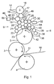
- Fig. 1 shows schematically and not to scale a printing unit comprising a plate cylinder 2, a blanket cylinder 3 contacting him, a printing cylinder 4 contacting them, an inking unit 6 and a dampening unit 8.
- a dampening solution liquid offset printing unit is a dampening solution liquid offset printing unit.
- the invention can also be used for a dry offset printing unit.
- the printing unit can be part of a sheet-fed offset printing press (printing of sheets) or a web offset printing press (printing of sheet-like printing material).
- the invention is also applicable to other types of printing machines (high pressure, gravure printing).
- the printing material 10 (sheet or web) passes through the nip 11 between the blanket cylinder 3 and the pressure roller 4. The image is transferred from the plate cylinder 2 on the blanket cylinder and from there to the substrate 10.
- the inking unit 6 may be of any type, which contains at least one ink roller driven by a motor and at least one non-driven ink roller, which latter is driven by the frictional resistance of its lateral surface with the lateral surface of another roller.
- the inking unit 6 of Fig. 1 includes, as an example, a paint box 14 and a roller train of ink rollers 16-27, of which a roller 16 is a so-called ductor roller for receiving ink from the ink fountain 14 and of which at least one roller is driven by an electric motor or other motor drive and not shown of which one or more rollers have no motor drive, but are driven only by touching their roll shell with an adjacent roll of this adjacent roll, which may also be a roller without motor drive.
- a doctor blade 30 is engageable toeuerrakeln of this roller 27 paint and other contaminants, preferably in a receptacle 32nd
- the dampening unit 8 contains a dampening solution tank 36 from which dampening solution liquid is applied to the peripheral surface of the plate cylinder 2 via a train of dampening rollers 38, 39, 40 and 42 to form ink-repelling areas corresponding to the printed image to be printed.
- a transfer roller 44 or more transfer roller may be provided which on the one hand in circumferential contact with a dampening roller, z. B. dampening roller 42, and on the other hand in circumferential contact with a paint roller, for example, the ink rollers 26 and 27.
- a printing unit roller cleaning device 46 for cleaning rotating rollers of a compactor, of which at least one roller is driven by a motor, for example, the ink roller 17 after the ductor roller 16, and of which at least one roller, for example 19, only by contact their Mantle surface is drivable with the lateral surface of one of the other rollers, and of which at least one roller is an ink roller for ink transfer.
- a motor for example, the ink roller 17 after the ductor roller 16, and of which at least one roller, for example 19, only by contact their Mantle surface is drivable with the lateral surface of one of the other rollers, and of which at least one roller is an ink roller for ink transfer.
- the cleaning device 46 includes a liquid applicator 48.
- This includes a manifold 49 having a plurality of liquid dispensing orifices 50 disposed along a first one of the rollers, e.g. B.
- the ink roller 18, which may be a motor-driven or a motor-driven roller, are positioned at a distance from her or positioned to liquid on the Apply lateral surface of the roller 18. This liquid is transferred by rotation of this roller 18 on the standing in mantle with her other rollers and from these rollers on other rollers in contact with them.
- the discharge openings 50 may be bores or nozzles used in bores.
- Liquid may be solvent, detergent, detergent or solvent-containing water, water with one or more additives which affect the printing process, pure water or any other liquid. Furthermore, the type of liquid can be changed during the washing process. For example, initially detergent or solvent or water containing it may be used to dissolve the paint from the rolls, and then rinsed with clean water.
- the liquid discharge openings 50 are small in size and shape such that liquid can only be applied to discrete moistening longitudinal zones 52 of this first roller 18, leaving non-moistening longitudinal zones 54 therebetween on this first roller 18.
- the width of a longitudinal moistening zone 52 is equal to the width of a liquid jet.
- the cleaning device 46 includes a liquid supply means 56 for supplying liquid to the discharge openings 50 and from there to the lateral surface of the first roller 18 in such an amount of liquid that the rotation of the rollers, the liquid from the discrete Befeuchtungszonen 52 of the first roller 18th on the lateral surface of the voltage applied to its lateral surface further roller, in the present example, the rollers 17 and 19, is transmitted.
- the liquid is transferred from the longitudinal moistening zones 52 of the first roller 18 to longitudinal moistening zones of the at least one further roller 17 and 19, leaving non-moistening longitudinal zones thereon.
- the amount of liquid per unit time of the discharge ports 50 may be constant or variable.
- Fig. 1 shows the liquid jets 51 only schematically.
- Fig. 1 shows on the left an applicator 48 whose liquid jets 51 are directed to the roller 18, and on the right another, alternatively or additionally usable application device 48, the liquid jets 51 are directed into the gusset between two rollers, such as the rollers 17 and 18th
- the liquid discharge openings 50 are designed to produce liquid jets 51 which have a point-shaped cross-section from the discharge openings 50 to the rolls 17 and 18, respectively.
- the applicator 48 is preferably provided at its lower end with a drip tray 64 for catching dripping washing liquid having a drain 66.
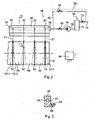
- Fig. 2 shows a possible embodiment of a liquid supply means 56.
- an automatic supply of detergent or solvent 76 may be provided in the detergent container 70.
- a line 78 which includes a pump 79 and a valve 80, to the distribution channel 49 of the liquid applicator 48.
- a fresh water supply line 92 which contains a valve 93, be provided from the fresh water connection 74 to the distribution channel 82.
- liquid supply device 56 only the supply of detergent-containing or solvent-containing washing liquid or only the supply of fresh water can be provided.
- the control of the valves and pumps is performed by an electronic control device 94, preferably in response to a higher-level machine operating program of the printing press.
- the invention is not limited to offset printing presses but can also be used for cleaning inking rollers in other types of printing presses.
- a doctor blade 30 it is also possible to use another dirt-wiping element, for example a cloth or a brush, which is applied to one of the rollers to be cleaned in order to strip off paint and washing liquid therefrom.
- another dirt-wiping element for example a cloth or a brush, which is applied to one of the rollers to be cleaned in order to strip off paint and washing liquid therefrom.
Landscapes
- Inking, Control Or Cleaning Of Printing Machines (AREA)
Claims (11)
- Procédé de nettoyage d'un cylindre de machine d'impression, pour nettoyer des cylindres rotatifs (16-27, 38, 39, 40, 42, 44) d'un train de cylindres, en particulier des cylindres d'encrage d'un encreur (6) d'impression offset, qui contient plusieurs cylindres successifs et mutuellement adjacents et qui comprend au moins un cylindre entraîné et au moins un cylindre non entraîné qui ne peut être entraîné que par son contact avec la surface d'enveloppe d'un cylindre voisin,
un liquide étant appliqué par machine sur la surface d'enveloppe d'au moins un premier (17, 18) de ces cylindres par des ouvertures de fourniture (50) d'un dispositif (48) d'application de liquide, pour dissoudre les encrassements,
le dispositif d'application de liquide présentant plusieurs ouvertures de fourniture (50) réparties sur la longueur du cylindre,
la rotation des cylindres transférant de plus le liquide depuis une surface d'enveloppe à la surface d'enveloppe d'un autre cylindre dans l'interstice entre cylindres,
un dispositif de raclage (30, 32) raclant le liquide sur un autre des cylindres en même temps que les encrassements qu'il a dissous, en particulier de l'encre et de la poussière de papier,
caractérisé en ce que
les jets de liquide (51) ne sont appliqués que sur certaines zones étroites d'humidification (52) de la largeur d'au moins un premier cylindre (18) en laissant des zones non humidifiées (54) entre elles,
en ce que le liquide est appliqué sur le ou les cylindres en une quantité par unité de temps suffisamment petite pour que les zones non humidifiées (54) du premier cylindre (17, 18) s'étendent jusqu'à la partie de la surface d'enveloppe en contact avec le cylindre voisin, de telle sorte qu'entre le premier cylindre (17, 18) sur lequel le liquide est appliqué et le cylindre adjacent, la résistance par frottement suffise pour l'entraînement en rotation,
en ce que le liquide ne s'écoule latéralement sur la totalité de la largeur des zones non humidifiées qu'après plusieurs rotations du cylindre,
en ce que sur au moins certains des cylindres qui suivent le premier cylindre du train de cylindres, le liquide n'est initialement transféré dans l'interstice entre les cylindres mutuellement adjacents que sur les zones humidifiées du cylindre suivant en laissant entre elles des zones non humidifiées et
en ce que le liquide ne s'y écoule latéralement sur la totalité de la largeur des zones non humidifiées qu'après plusieurs rotations du cylindre de manière à garantir entre le cylindre non entraîné et le ou les cylindres qui lui sont adjacents une résistance de frottement qui suffit pour l'entraînement en rotation. - Procédé de nettoyage de cylindres de machine d'impression selon la revendication 1, caractérisé en ce que les quelques cylindres qui suivent le premier cylindre (18) comprennent le cylindre sur lequel le liquide est raclé.
- Procédé de nettoyage de cylindres de machine d'impression selon au moins l'une des revendications précédentes, caractérisé en ce que les zones humidifiées (52) du ou des premiers cylindres (18) sont plus étroites que les zones non humidifiées (54).
- Procédé de nettoyage de cylindres de machine d'impression, caractérisé en ce que les jets de liquide (51) sont injectés dans le biseau situé entre le premier cylindre (18) et un autre cylindre (17) qui lui est adjacent.
- Procédé de nettoyage de cylindres de machine d'impression, caractérisé en ce que les jets de liquide (51) qui aboutissent en forme de feuille sur le ou les premiers cylindres (18) sont orientés de manière à y atterrir doucement.
- Procédé de nettoyage de cylindres de machine d'impression, caractérisé en ce que les jets de liquide (51) provenant des ouvertures de fourniture (50) ont une section transversale ponctuelle avant d'aboutir sur le ou les premiers cylindres, pour former des zones humidifiées (52) suffisamment étroites en largeur.
- Dispositif de nettoyage de cylindres de machine d'impression, pour nettoyer les cylindres rotatifs (16-27, 38, 39, 49, 42, 44) d'un train de cylindres, en particulier des cylindres d'encrage d'un encreur (6) d'impression offset, qui contient plusieurs cylindres successifs et mutuellement adjacents et comprenant au moins un cylindre entraîné et au moins un cylindre non entraîné qui ne peut être entraîné que par son contact avec la surface d'enveloppe d'un cylindre voisin,
le dispositif de nettoyage contenant un dispositif (48) d'application de liquide qui présente plusieurs ouvertures de fourniture (50) réparties sur la longueur des cylindres et par lesquelles un liquide destiné à dissoudre les encrassements, en particulier l'encre et la poussière de papier, est appliqué à la machine sur la surface d'enveloppe d'au moins un premier des cylindres (17, 18),
la rotation des cylindres transférant le liquide d'une surface d'enveloppe à l'autre dans l'interstice entre les cylindres,
un dispositif de raclage (30, 32) raclant le liquide sur un autre des cylindres en même temps que les encrassements qu'il a dissous, caractérisé en ce que
les ouvertures de fourniture (50) ont une forme d'ouverture et une distance mutuelle dans le sens de la longueur des cylindres telles que lorsque les jets de liquide (51) aboutissent sur le ou les premiers cylindres (17, 18), ils présentent sur toute leur longueur une distance mutuelle dans le sens de la longueur des cylindres et qu'ainsi ils forment sur le premier cylindre (17, 18) des zones humidifiées (52) séparées qui correspondent à la largeur du jet en laissant entre elles des zones non humidifiées (54) sur lesquelles aucun jet de liquide n'aboutit, et
en ce que les zones non humidifiées (54) s'étendent sur le premier cylindre (17, 18) jusqu'à la partie de la surface d'enveloppe en contact avec le cylindre voisin de manière à garantir entre le premier cylindre (17, 18) sur lequel le liquide est appliqué et le cylindre qui lui est adjacent une résistance de frottement qui suffit pour l'entraînement en rotation. - Dispositif de nettoyage de cylindres de machine d'impression selon la revendication 7, caractérisé en ce que la distance entre les ouvertures de fourniture (50) dans le sens de la longueur des cylindres est suffisamment grande et le jet de liquide (51) qu'elles délivrent sur la surface du cylindre est suffisamment étroit pour que les zones non humidifiées (54) situées entre elles sur le premier cylindre (17, 18) soient plus larges que les zones humidifiées (52).
- Dispositif de nettoyage de cylindres de machine d'impression selon les revendications 7 ou 8, caractérisé en ce que les ouvertures de fourniture (50) orientent les jets de liquide (51) dans le biseau situé entre le premier cylindre (18) et un autre premier cylindre (17) qui lui est adjacent.
- Dispositif de nettoyage de cylindres de machine d'impression selon au moins l'une des revendications 7 à 9, caractérisé en ce que les jets de liquide (51) tombent en forme de feuille.
- Dispositif de nettoyage de cylindres de machine d'impression selon l'une des revendications 7 à 10, caractérisé en ce que les jets de liquides (51) ont une section transversale ponctuelle lorsqu'ils aboutissent sur le ou les premiers cylindres (17, 18).
Applications Claiming Priority (3)
| Application Number | Priority Date | Filing Date | Title |
|---|---|---|---|
| DE10153968 | 2001-11-06 | ||
| DE10153968A DE10153968A1 (de) | 2001-11-06 | 2001-11-06 | Druckmaschinenwalzen-Reinigungsverfahren und -vorrichtung |
| PCT/EP2002/012318 WO2003039874A1 (fr) | 2001-11-06 | 2002-11-05 | Procede et dispositif de nettoyage de cylindres d'une presse a imprimer |
Publications (2)
| Publication Number | Publication Date |
|---|---|
| EP1441908A1 EP1441908A1 (fr) | 2004-08-04 |
| EP1441908B1 true EP1441908B1 (fr) | 2009-10-14 |
Family
ID=7704464
Family Applications (1)
| Application Number | Title | Priority Date | Filing Date |
|---|---|---|---|
| EP02785362A Expired - Lifetime EP1441908B1 (fr) | 2001-11-06 | 2002-11-05 | Procede et dispositif de nettoyage de cylindres d'une presse a imprimer |
Country Status (6)
| Country | Link |
|---|---|
| US (1) | US20040050277A1 (fr) |
| EP (1) | EP1441908B1 (fr) |
| JP (1) | JP2004521793A (fr) |
| CN (1) | CN1592685A (fr) |
| DE (2) | DE10153968A1 (fr) |
| WO (1) | WO2003039874A1 (fr) |
Cited By (2)
| Publication number | Priority date | Publication date | Assignee | Title |
|---|---|---|---|---|
| DE102013213059A1 (de) | 2012-07-06 | 2014-01-09 | Koenig & Bauer Aktiengesellschaft | Vorrichtung und Verfahren zum Aufbringen und Dosieren von Reinigungsflüssigkeit |
| EP3882033A1 (fr) | 2020-03-19 | 2021-09-22 | Heidelberger Druckmaschinen AG | Procédé de lavage d'un mécanisme d'encrage d'une machine d'impression |
Families Citing this family (8)
| Publication number | Priority date | Publication date | Assignee | Title |
|---|---|---|---|---|
| DE102005038258A1 (de) * | 2005-08-12 | 2007-02-22 | Baldwin Germany Gmbh | Farbwalzenrakelvorrichtung und Auskleidung für eine Rakelwanne hiervon |
| US7546803B2 (en) * | 2006-01-30 | 2009-06-16 | Toppan Printing Co., Ltd. | Letterpress printing machine |
| JP2008143180A (ja) * | 2006-12-07 | 2008-06-26 | Heidelberger Druckmas Ag | インキ装置の洗浄装置を備えた印刷機 |
| DE202007018741U1 (de) | 2007-12-08 | 2009-04-02 | Hartmut Lehmann Metallbau Gmbh | Vorrichtung zur Reinigung von Druckpapier |
| DE102008062027B4 (de) * | 2008-01-31 | 2018-05-17 | Heidelberger Druckmaschinen Ag | Druckmaschine mit einem Anilox-Farbwerk mit zugehöriger Wascheinrichtung |
| DE202010012485U1 (de) | 2010-09-10 | 2010-12-30 | Detho, Farooq | Verarbeitungsmaschine mit einer Reinigungsvorrichtung |
| JP2016083863A (ja) * | 2014-10-27 | 2016-05-19 | 株式会社小森コーポレーション | 印刷機の洗浄装置 |
| CN111391509B (zh) * | 2020-04-20 | 2024-10-08 | 深圳劲鑫科技股份有限公司 | 一种喷头擦拭装置及喷印设备 |
Family Cites Families (9)
| Publication number | Priority date | Publication date | Assignee | Title |
|---|---|---|---|---|
| US5303652A (en) * | 1992-02-13 | 1994-04-19 | Baldwin Technology Corporation | Spray blanket cleaning system |
| DE4424581C1 (de) * | 1994-07-13 | 1995-10-19 | Roland Man Druckmasch | Vorrichtung zum Entfernen von Farbe aus einem Farbwerk |
| DE29703074U1 (de) * | 1997-02-21 | 1997-04-30 | Maschinenfabrik Goebel Gmbh, 64293 Darmstadt | Einrichtung zum Reinigen |
| DE19711545B4 (de) * | 1997-03-20 | 2005-08-04 | Heidelberger Druckmaschinen Ag | Farbwerk für Rotationsdruckmaschinen |
| US5868073A (en) * | 1997-04-11 | 1999-02-09 | Komori Corporation | Cleaning apparatus for web offset printing press |
| DE19816660A1 (de) * | 1997-09-17 | 1999-03-18 | Heidelberger Druckmasch Ag | Farbwerk für Rotationsdruckmaschinen |
| DE10000903A1 (de) * | 1999-02-05 | 2000-08-10 | Heidelberger Druckmasch Ag | Verfahren zum Betrieb einer Druckmaschine und Druckmaschine zur Durchführung des Verfahrens |
| DE19936144B4 (de) * | 1999-07-31 | 2006-09-21 | Koenig & Bauer Ag | Einrichtung zum Aufbringen von Flüssigkeit |
| IT1321267B1 (it) * | 2000-05-19 | 2004-01-08 | Marco Corti | Metodo e dispositivo per la pulitura dei cilindri in caucciu' dellemacchine da stampa, particolarmente del tipo cosiddette a bobina. |
-
2001
- 2001-11-06 DE DE10153968A patent/DE10153968A1/de not_active Withdrawn
-
2002
- 2002-11-05 WO PCT/EP2002/012318 patent/WO2003039874A1/fr not_active Ceased
- 2002-11-05 DE DE50213929T patent/DE50213929D1/de not_active Expired - Lifetime
- 2002-11-05 EP EP02785362A patent/EP1441908B1/fr not_active Expired - Lifetime
- 2002-11-05 US US10/250,545 patent/US20040050277A1/en not_active Abandoned
- 2002-11-05 JP JP2003541942A patent/JP2004521793A/ja active Pending
- 2002-11-05 CN CN02802894.5A patent/CN1592685A/zh active Pending
Cited By (2)
| Publication number | Priority date | Publication date | Assignee | Title |
|---|---|---|---|---|
| DE102013213059A1 (de) | 2012-07-06 | 2014-01-09 | Koenig & Bauer Aktiengesellschaft | Vorrichtung und Verfahren zum Aufbringen und Dosieren von Reinigungsflüssigkeit |
| EP3882033A1 (fr) | 2020-03-19 | 2021-09-22 | Heidelberger Druckmaschinen AG | Procédé de lavage d'un mécanisme d'encrage d'une machine d'impression |
Also Published As
| Publication number | Publication date |
|---|---|
| EP1441908A1 (fr) | 2004-08-04 |
| US20040050277A1 (en) | 2004-03-18 |
| WO2003039874A1 (fr) | 2003-05-15 |
| JP2004521793A (ja) | 2004-07-22 |
| DE50213929D1 (de) | 2009-11-26 |
| DE10153968A1 (de) | 2003-05-22 |
| CN1592685A (zh) | 2005-03-09 |
Similar Documents
| Publication | Publication Date | Title |
|---|---|---|
| EP1097813B1 (fr) | Machine d'impression rotative à feuilles comportant des unités d'impression pour l'impression en polychromie et au moins une unité de couchage | |
| DE10000903A1 (de) | Verfahren zum Betrieb einer Druckmaschine und Druckmaschine zur Durchführung des Verfahrens | |
| DE102009006268B4 (de) | Verfahren zum Reinigen einer Mantelfläche eines Gummituchzylinders einer Nassoffsetdruckmaschine | |
| EP1441908B1 (fr) | Procede et dispositif de nettoyage de cylindres d'une presse a imprimer | |
| EP0654350A1 (fr) | Procédé pour le nettoyage automatique de cyclindres dans des machines d'impression à commande centrale | |
| DE3640295C2 (de) | Verfahren zur Vermeidung des Überfärbens von Farbwerken an Druckmaschinen | |
| EP0715955B1 (fr) | Procédé et appareil à nettoyer un cylindre d'une machine d'impression | |
| DE4424590C2 (de) | Einrichtung zur Reinigung eines Farbwerkes einer Offsetdruckmaschine | |
| DE102004005576A1 (de) | Verfahren zum Betrieb einer Lackier- oder Druckmaschine | |
| DE3838674C2 (fr) | ||
| DE102005056812B4 (de) | Verfahren zum Waschen eines Anilox-Farbwerks einer Druckmaschine | |
| EP0692381A2 (fr) | Dispositif pour enlever de l'encre d'un encrier | |
| DE10252013B4 (de) | Reinigung von Walzen in Druckmaschinen | |
| DE10236781B4 (de) | Beschichtungseinrichtung für eine Druck- oder Beschichtungsmaschine | |
| DE10112756B4 (de) | Filmfarbwerk in einer Druckmaschine und Verfahren zu dessen Reinigung | |
| DE102022100518A1 (de) | Verfahren zur Reinigung eines Farbwerkes und Farbwerk | |
| EP0711666A2 (fr) | Dispositif de nettoyage pour le dispositif de guidage de feuilles d'une machine d'impression rotative | |
| DE19645169C2 (de) | Verfahren zur Reinigung von Zylindern und Walzen in einer Druckmaschine | |
| DE102007015595B3 (de) | Vorrichtung zum Druckplattenwechsel an einer Verarbeitungsmaschine | |
| DE20307718U1 (de) | Reinigungsvorrichtung für einen Zylinder einer Verarbeitungsmaschine | |
| DE29819374U1 (de) | Reinigungsvorrichtung zum Reinigen der Mantelfläche eines Zylinders in einer Druckmaschine | |
| DE19853362C5 (de) | Feuchtwerk für eine Offsetdruckmaschine | |
| EP1106353B1 (fr) | Procédé et dispositif pour le dépoussiérage d'un support d'impression | |
| DE4437018B4 (de) | Druckmaschine | |
| EP1683632A2 (fr) | Dispositif de mouillage et dispositif de nettoyage d'une machine à imprimer |
Legal Events
| Date | Code | Title | Description |
|---|---|---|---|
| PUAI | Public reference made under article 153(3) epc to a published international application that has entered the european phase |
Free format text: ORIGINAL CODE: 0009012 |
|
| 17P | Request for examination filed |
Effective date: 20040506 |
|
| AK | Designated contracting states |
Kind code of ref document: A1 Designated state(s): AT BE BG CH CY CZ DE DK EE ES FI FR GB GR IE IT LI LU MC NL PT SE SK TR |
|
| RAP1 | Party data changed (applicant data changed or rights of an application transferred) |
Owner name: BALDWIN GERMANY GMBH |
|
| 17Q | First examination report despatched |
Effective date: 20070911 |
|
| GRAP | Despatch of communication of intention to grant a patent |
Free format text: ORIGINAL CODE: EPIDOSNIGR1 |
|
| GRAS | Grant fee paid |
Free format text: ORIGINAL CODE: EPIDOSNIGR3 |
|
| GRAA | (expected) grant |
Free format text: ORIGINAL CODE: 0009210 |
|
| AK | Designated contracting states |
Kind code of ref document: B1 Designated state(s): DE IT |
|
| REF | Corresponds to: |
Ref document number: 50213929 Country of ref document: DE Date of ref document: 20091126 Kind code of ref document: P |
|
| PLBI | Opposition filed |
Free format text: ORIGINAL CODE: 0009260 |
|
| PLAX | Notice of opposition and request to file observation + time limit sent |
Free format text: ORIGINAL CODE: EPIDOSNOBS2 |
|
| PLAF | Information modified related to communication of a notice of opposition and request to file observations + time limit |
Free format text: ORIGINAL CODE: EPIDOSCOBS2 |
|
| 26 | Opposition filed |
Opponent name: KOENIG & BAUER AG BOGENOFFSETMASCHINEN Effective date: 20100714 |
|
| PLBB | Reply of patent proprietor to notice(s) of opposition received |
Free format text: ORIGINAL CODE: EPIDOSNOBS3 |
|
| PLCK | Communication despatched that opposition was rejected |
Free format text: ORIGINAL CODE: EPIDOSNREJ1 |
|
| PLBN | Opposition rejected |
Free format text: ORIGINAL CODE: 0009273 |
|
| STAA | Information on the status of an ep patent application or granted ep patent |
Free format text: STATUS: OPPOSITION REJECTED |
|
| 27O | Opposition rejected |
Effective date: 20111020 |
|
| REG | Reference to a national code |
Ref country code: DE Ref legal event code: R100 Ref document number: 50213929 Country of ref document: DE Effective date: 20111020 |
|
| PGFP | Annual fee paid to national office [announced via postgrant information from national office to epo] |
Ref country code: IT Payment date: 20131126 Year of fee payment: 12 |
|
| PG25 | Lapsed in a contracting state [announced via postgrant information from national office to epo] |
Ref country code: IT Free format text: LAPSE BECAUSE OF NON-PAYMENT OF DUE FEES Effective date: 20141105 |
|
| PGFP | Annual fee paid to national office [announced via postgrant information from national office to epo] |
Ref country code: DE Payment date: 20201125 Year of fee payment: 19 |
|
| REG | Reference to a national code |
Ref country code: DE Ref legal event code: R119 Ref document number: 50213929 Country of ref document: DE |
|
| PG25 | Lapsed in a contracting state [announced via postgrant information from national office to epo] |
Ref country code: DE Free format text: LAPSE BECAUSE OF NON-PAYMENT OF DUE FEES Effective date: 20220601 |