EP1441908B1 - Cleaning method and device for a printing roller - Google Patents
Cleaning method and device for a printing roller Download PDFInfo
- Publication number
- EP1441908B1 EP1441908B1 EP02785362A EP02785362A EP1441908B1 EP 1441908 B1 EP1441908 B1 EP 1441908B1 EP 02785362 A EP02785362 A EP 02785362A EP 02785362 A EP02785362 A EP 02785362A EP 1441908 B1 EP1441908 B1 EP 1441908B1
- Authority
- EP
- European Patent Office
- Prior art keywords
- roll
- liquid
- rolls
- printing
- wetting zones
- Prior art date
- Legal status (The legal status is an assumption and is not a legal conclusion. Google has not performed a legal analysis and makes no representation as to the accuracy of the status listed.)
- Expired - Lifetime
Links
- 238000004140 cleaning Methods 0.000 title claims description 25
- 238000000034 method Methods 0.000 title claims description 11
- 238000007639 printing Methods 0.000 title description 22
- 239000007788 liquid Substances 0.000 claims description 76
- 238000009736 wetting Methods 0.000 claims description 18
- 230000002093 peripheral effect Effects 0.000 claims description 11
- 238000007645 offset printing Methods 0.000 claims description 8
- 238000011109 contamination Methods 0.000 claims description 2
- 230000000284 resting effect Effects 0.000 claims 8
- 239000000428 dust Substances 0.000 claims 2
- 239000003599 detergent Substances 0.000 description 12
- XLYOFNOQVPJJNP-UHFFFAOYSA-N water Substances O XLYOFNOQVPJJNP-UHFFFAOYSA-N 0.000 description 10
- 239000002904 solvent Substances 0.000 description 9
- 239000003973 paint Substances 0.000 description 7
- 239000013505 freshwater Substances 0.000 description 6
- 238000005406 washing Methods 0.000 description 6
- 239000007921 spray Substances 0.000 description 4
- 239000000654 additive Substances 0.000 description 2
- 239000004744 fabric Substances 0.000 description 2
- 239000012530 fluid Substances 0.000 description 2
- 239000000463 material Substances 0.000 description 2
- 238000004804 winding Methods 0.000 description 2
- 238000009825 accumulation Methods 0.000 description 1
- 239000000356 contaminant Substances 0.000 description 1
- 238000007646 gravure printing Methods 0.000 description 1
- 239000000203 mixture Substances 0.000 description 1
- 238000005096 rolling process Methods 0.000 description 1
- 230000003068 static effect Effects 0.000 description 1
- 239000000758 substrate Substances 0.000 description 1
Images
Classifications
-
- B—PERFORMING OPERATIONS; TRANSPORTING
- B41—PRINTING; LINING MACHINES; TYPEWRITERS; STAMPS
- B41F—PRINTING MACHINES OR PRESSES
- B41F35/00—Cleaning arrangements or devices
-
- B—PERFORMING OPERATIONS; TRANSPORTING
- B41—PRINTING; LINING MACHINES; TYPEWRITERS; STAMPS
- B41P—INDEXING SCHEME RELATING TO PRINTING, LINING MACHINES, TYPEWRITERS, AND TO STAMPS
- B41P2235/00—Cleaning
- B41P2235/10—Cleaning characterised by the methods or devices
- B41P2235/26—Spraying devices
Definitions
- the invention relates to a printing press roller cleaning method and a printing press roller cleaning device according to the claims.
- a cleaning device of this kind is from the DE-A-198 16 660 known .
- Ink rollers of an inking unit in a printing unit for offset printing are moistened by a so-called spray tube for dissolving the paint with liquid, which is sprayed onto one of the rollers and doctored down on another roller.
- One or more of the inking rollers are driven, while other rollers are not driven, but are rotated only by the contact of their roll shell with the roll shell of an adjacent roll.
- the cleaning process must be carried out in a short period of time to shorten the downtime for the printing operation.
- the liquid must therefore be transferred from the roll, which is moistened with the liquid from the spray tube, as quickly and uniformly as possible to all rolls of the compactor. If little liquid is sprayed onto the one roller, it will take a long time for all rollers to be moistened.
- the invention enables the problem to be solved in a simple and inexpensive way to achieve a safe cleaning of all rolls of a compactor in a short time.
- the invention ensures that the liquid is rapidly applied and distributed in a short time to all rollers up to and including the doctored-off roller.
- the invention prevents over-rolling of rolls and thereby slippage or stagnation of non-driven rolls.
- Standing rollers prevent the transfer of fluid to other rollers and thereby cause a liquid accumulation in the roller winding, from which liquid is laterally squeezed out.
- the Rushbefeuchturigszonen ensure sufficient frictional adhesion between the rollers through which all non-driven rollers are rotated by adjacent rollers and no rollers slip due to over-wetting of the adjacent roller. Furthermore, a fast fluid transfer to all rollers is achieved.
- the invention uses substantially fewer discharge ports or nozzles than the prior art.
- Liquid may be solvent, detergent, detergent or solvent-containing water, water with one or more additives which affect the printing process, pure water or any other liquid. Furthermore, the type of liquid can be changed during the washing process. For example, initially detergent or solvent or water containing it may be used to dissolve the paint from the rolls, and then rinsed with clean water.
- Rollers also include press cylinders, but especially inking rollers.
- a roller may be driven by an electric motor, a pneumatic motor or a hydraulic motor, or by a drive connection from another roller or cylinder of the printing press.
- Non-driven roller is a roller which rotates only by being in contact with an adjacent roller and being co-rotated by the frictional resistance.
- Dot-shaped cross-section of the liquid jets means a jet with a small cross-section and distance from each other over the entire jet length from the nozzle to the point of impingement on the roll, in contrast to a spray jet or a very wide flat jet which already on impact with the roll or even before each other touch or mix with each other.
- “Scraper device” for stripping the liquid and possibly detached from it roll contamination This may be a squeegee, a brush or a cloth or other element, with which the liquid and possibly dissolved by her dirt from a roller is removable.
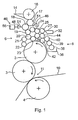
- Fig. 1 shows schematically and not to scale a printing unit comprising a plate cylinder 2, a blanket cylinder 3 contacting him, a printing cylinder 4 contacting them, an inking unit 6 and a dampening unit 8.
- a dampening solution liquid offset printing unit is a dampening solution liquid offset printing unit.
- the invention can also be used for a dry offset printing unit.
- the printing unit can be part of a sheet-fed offset printing press (printing of sheets) or a web offset printing press (printing of sheet-like printing material).
- the invention is also applicable to other types of printing machines (high pressure, gravure printing).
- the printing material 10 (sheet or web) passes through the nip 11 between the blanket cylinder 3 and the pressure roller 4. The image is transferred from the plate cylinder 2 on the blanket cylinder and from there to the substrate 10.
- the inking unit 6 may be of any type, which contains at least one ink roller driven by a motor and at least one non-driven ink roller, which latter is driven by the frictional resistance of its lateral surface with the lateral surface of another roller.
- the inking unit 6 of Fig. 1 includes, as an example, a paint box 14 and a roller train of ink rollers 16-27, of which a roller 16 is a so-called ductor roller for receiving ink from the ink fountain 14 and of which at least one roller is driven by an electric motor or other motor drive and not shown of which one or more rollers have no motor drive, but are driven only by touching their roll shell with an adjacent roll of this adjacent roll, which may also be a roller without motor drive.
- a doctor blade 30 is engageable toeuerrakeln of this roller 27 paint and other contaminants, preferably in a receptacle 32nd
- the dampening unit 8 contains a dampening solution tank 36 from which dampening solution liquid is applied to the peripheral surface of the plate cylinder 2 via a train of dampening rollers 38, 39, 40 and 42 to form ink-repelling areas corresponding to the printed image to be printed.
- a transfer roller 44 or more transfer roller may be provided which on the one hand in circumferential contact with a dampening roller, z. B. dampening roller 42, and on the other hand in circumferential contact with a paint roller, for example, the ink rollers 26 and 27.
- a printing unit roller cleaning device 46 for cleaning rotating rollers of a compactor, of which at least one roller is driven by a motor, for example, the ink roller 17 after the ductor roller 16, and of which at least one roller, for example 19, only by contact their Mantle surface is drivable with the lateral surface of one of the other rollers, and of which at least one roller is an ink roller for ink transfer.
- a motor for example, the ink roller 17 after the ductor roller 16, and of which at least one roller, for example 19, only by contact their Mantle surface is drivable with the lateral surface of one of the other rollers, and of which at least one roller is an ink roller for ink transfer.
- the cleaning device 46 includes a liquid applicator 48.
- This includes a manifold 49 having a plurality of liquid dispensing orifices 50 disposed along a first one of the rollers, e.g. B.
- the ink roller 18, which may be a motor-driven or a motor-driven roller, are positioned at a distance from her or positioned to liquid on the Apply lateral surface of the roller 18. This liquid is transferred by rotation of this roller 18 on the standing in mantle with her other rollers and from these rollers on other rollers in contact with them.
- the discharge openings 50 may be bores or nozzles used in bores.
- Liquid may be solvent, detergent, detergent or solvent-containing water, water with one or more additives which affect the printing process, pure water or any other liquid. Furthermore, the type of liquid can be changed during the washing process. For example, initially detergent or solvent or water containing it may be used to dissolve the paint from the rolls, and then rinsed with clean water.
- the liquid discharge openings 50 are small in size and shape such that liquid can only be applied to discrete moistening longitudinal zones 52 of this first roller 18, leaving non-moistening longitudinal zones 54 therebetween on this first roller 18.
- the width of a longitudinal moistening zone 52 is equal to the width of a liquid jet.
- the cleaning device 46 includes a liquid supply means 56 for supplying liquid to the discharge openings 50 and from there to the lateral surface of the first roller 18 in such an amount of liquid that the rotation of the rollers, the liquid from the discrete Befeuchtungszonen 52 of the first roller 18th on the lateral surface of the voltage applied to its lateral surface further roller, in the present example, the rollers 17 and 19, is transmitted.
- the liquid is transferred from the longitudinal moistening zones 52 of the first roller 18 to longitudinal moistening zones of the at least one further roller 17 and 19, leaving non-moistening longitudinal zones thereon.
- the amount of liquid per unit time of the discharge ports 50 may be constant or variable.
- Fig. 1 shows the liquid jets 51 only schematically.
- Fig. 1 shows on the left an applicator 48 whose liquid jets 51 are directed to the roller 18, and on the right another, alternatively or additionally usable application device 48, the liquid jets 51 are directed into the gusset between two rollers, such as the rollers 17 and 18th
- the liquid discharge openings 50 are designed to produce liquid jets 51 which have a point-shaped cross-section from the discharge openings 50 to the rolls 17 and 18, respectively.
- the applicator 48 is preferably provided at its lower end with a drip tray 64 for catching dripping washing liquid having a drain 66.
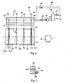
- Fig. 2 shows a possible embodiment of a liquid supply means 56.
- an automatic supply of detergent or solvent 76 may be provided in the detergent container 70.
- a line 78 which includes a pump 79 and a valve 80, to the distribution channel 49 of the liquid applicator 48.
- a fresh water supply line 92 which contains a valve 93, be provided from the fresh water connection 74 to the distribution channel 82.
- liquid supply device 56 only the supply of detergent-containing or solvent-containing washing liquid or only the supply of fresh water can be provided.
- the control of the valves and pumps is performed by an electronic control device 94, preferably in response to a higher-level machine operating program of the printing press.
- the invention is not limited to offset printing presses but can also be used for cleaning inking rollers in other types of printing presses.
- a doctor blade 30 it is also possible to use another dirt-wiping element, for example a cloth or a brush, which is applied to one of the rollers to be cleaned in order to strip off paint and washing liquid therefrom.
- another dirt-wiping element for example a cloth or a brush, which is applied to one of the rollers to be cleaned in order to strip off paint and washing liquid therefrom.
Landscapes
- Inking, Control Or Cleaning Of Printing Machines (AREA)
Description
Die Erfindung betrifft ein Druckmaschinenwalzen-Reinigungsverfahren und eine Druckmaschinenwalzen-Reinigungsvorrichtung gemäß den Patentansprüchen.The invention relates to a printing press roller cleaning method and a printing press roller cleaning device according to the claims.
Eine Reinigungsvorrichtung dieser Art ist aus der
Farbwalzen eines Farbwerkes in einem Druckwerk für den Offsetdruck werden durch ein sogenanntes Sprührohr zum Lösen der Farbe mit Flüssigkeit befeuchtet, welche auf eine der Walzen aufgespritzt und an einer anderen Walze abgerakelt wird. Eine oder mehrere der Farbwerkswalzen werden angetrieben, während andere Walzen nicht angetrieben werden, sondern nur durch den Kontakt ihres Walzenmantels mit dem Walzenmantel einer benachbarten Walze mitgedreht werden. Der Reinigungsvorgang muß in kurzer Zeitdauer durchgeführt werden, um die Stillstandszeiten für den Druckbetrieb zu verkürzen. Die Flüssigkeit muß deshalb von der Walze, welche mit der Flüssigkeit von dem Sprührohr befeuchtet wird, möglichst schnell und gleichmäßig auf alle Walzen des Walzenzuges übertragen werden. Wenn wenig Flüssigkeit auf die eine Walze aufgespritzt wird, dauert es lange, bis alle Walzen befeuchtet sind. Wenn viel Flüssigkeit auf die eine Walze aufgespritzt wird, besteht die Gefahr, dass die Flüssigkeit im Walzenspalt oder bereits davor im Walzenzwickel gestaut wird und dadurch seitlich in Walzenlängsrichtung aus dem Walzenzug herausläuft. Ferner besteht die Gefahr einer Übernässung der ersten oder von mehreren folgenden Walzen des Walzenzuges, so dass die nicht angetriebenen Walzen mangels Haftreibung von benachbarten Walze nicht mehr mitgedreht werden order sprunghaft stoppen und rotieren und dabei Flüssigkeit vermischt mit gelöster Farbe abschleudern. Die Flüssigkeit und damit auch die von ihr gelöste Farbe wird an der stillstehenden Walze nicht mehr übertragen und somit auch nicht bis zur Rakelvorrichtung der abgerakelten Walze übertragen. Damit wird das Farbwerk nicht mehr ausreichend gereinigt, so dass es manuell gereinigt werden muß.Ink rollers of an inking unit in a printing unit for offset printing are moistened by a so-called spray tube for dissolving the paint with liquid, which is sprayed onto one of the rollers and doctored down on another roller. One or more of the inking rollers are driven, while other rollers are not driven, but are rotated only by the contact of their roll shell with the roll shell of an adjacent roll. The cleaning process must be carried out in a short period of time to shorten the downtime for the printing operation. The liquid must therefore be transferred from the roll, which is moistened with the liquid from the spray tube, as quickly and uniformly as possible to all rolls of the compactor. If little liquid is sprayed onto the one roller, it will take a long time for all rollers to be moistened. If a lot of liquid is sprayed onto the one roll, there is a risk that the liquid in the nip or even before it is jammed in the roll winding and thereby runs out laterally in the roll longitudinal direction of the compactor. Furthermore, there is a risk of over-wetting of the first or several subsequent rolls of the compactor, so that the non-driven rollers are no longer rotated due to lack of static friction of adjacent roller or stop and rotate abruptly, thereby spun liquid mixed with dissolved color. The liquid and thus also the color dissolved by it is no longer transferred to the stationary roll and thus also not transferred to the squeegee device of the doctored roller. Thus, the inking is not cleaned enough, so it must be cleaned manually.
Durch die Erfindung soll die Aufgabe gelöst werden, auf einfache und preiswerte Art und Weise eine sichere Reinigung von allen Walzen eines Walzenzuges in kurzer Zeit zu erzielen.The invention enables the problem to be solved in a simple and inexpensive way to achieve a safe cleaning of all rolls of a compactor in a short time.
Diese Aufgabe wird gemäß der Erfindung durch die Merkmale von Anspruch 1 bzw. von Anspruch 7 gelöst.This object is achieved according to the invention by the features of claim 1 and of claim 7.
Weitere Merkmale der Erfindung sind in den Unteransprüchen enthalten.Further features of the invention are contained in the subclaims.
Durch die Erfindung wird sichergestellt, dass die Flüssigkeit in kurzer Zeit auf alle Walzen bis einschließlich der abgerakelten Walze schnell aufgetragen und verteilt wird. Die Erfindung verhindert eine Übernässung von Walzen und dadurch ein Rutschen oder Stehenbleiben von nicht-angetriebenen Walzen. Stehende Walzen verhindern die Flüssigkeitsübertragung auf weitere Walzen und bewirken dadurch einen Flüssigkeitsstau im Walzenzwickel, aus welchem dann Flüssigkeit seitlich rausgequetscht wird. Die Nichtbefeuchturigszonen gewährleisten eine ausreichende Reibungshaftung zwischen den Walzen, durch welche alle nicht angetriebenen Walzen von benachbarten Walzen mitgedreht werden und keine Walzen wegen Übernässung der benachbarten Walze rutschen. Ferner wird eine schnelle Flüssigkeitsübertragung auf alle Walzen erzielt. Die Erfindung benutzt wesentlich weniger Abgabeöffnungen oder Düsen als der Stand der Technik.The invention ensures that the liquid is rapidly applied and distributed in a short time to all rollers up to and including the doctored-off roller. The invention prevents over-rolling of rolls and thereby slippage or stagnation of non-driven rolls. Standing rollers prevent the transfer of fluid to other rollers and thereby cause a liquid accumulation in the roller winding, from which liquid is laterally squeezed out. The Nichtbefeuchturigszonen ensure sufficient frictional adhesion between the rollers through which all non-driven rollers are rotated by adjacent rollers and no rollers slip due to over-wetting of the adjacent roller. Furthermore, a fast fluid transfer to all rollers is achieved. The invention uses substantially fewer discharge ports or nozzles than the prior art.
"Flüssigkeit" kann Lösemittel, Waschmittel, Waschmittel oder Lösemittel enthaltendes Wasser, Wasser mit einem oder mehreren Zusätzen, welche den Druckprozeß beeinflussen, reines Wasser oder jede andere Flüssigkeit sein. Ferner kann die Art der Flüssigkeit während des Waschvorganges verändert werden. Beispielsweise kann anfänglich Waschmittel oder Lösemittel oder solches enthaltendes Wasser zum Lösen der Farbe von den Walzen verwendet werden, und anschließend mit klarem Wasser nachgespült werden. "Walzen" beinhalten auch Durckmaschinen-Zylinder, insbesondere jedoch Farbwerkswalzen."Liquid" may be solvent, detergent, detergent or solvent-containing water, water with one or more additives which affect the printing process, pure water or any other liquid. Furthermore, the type of liquid can be changed during the washing process. For example, initially detergent or solvent or water containing it may be used to dissolve the paint from the rolls, and then rinsed with clean water. "Rollers" also include press cylinders, but especially inking rollers.
"Angetriebene Walze": Eine Walze kann von einem Elektromotor, von einem Pneumatikmotor oder einem Hydraulikmotor oder durch eine Antriebsverbindung von einer anderen Walze oder einem anderen Zylinder der Druckmaschine angetrieben werden."Driven Roller": A roller may be driven by an electric motor, a pneumatic motor or a hydraulic motor, or by a drive connection from another roller or cylinder of the printing press.
"Nicht angetriebene Walze" ist eine Walze, welche nur dadurch rotiert, dass sie an einer benachbarten Walze anliegt und durch den Reibungswiderstand mit dieser mitgedreht wird."Non-driven roller" is a roller which rotates only by being in contact with an adjacent roller and being co-rotated by the frictional resistance.
"Punktförmiger Querschnitt der Flüssigkeitsstrahlen" bedeutet ein Strahl mit kleinem Querschnitt und Abstand voneinander auf der gesamten Strahllänge von der Düse bis zur Auftreffstelle auf die Walze, im Gegensatz zu einem Sprühstrahl oder einem sehr breiten Flachstrahl, welche bereits beim Auftreffen auf Walze oder schon vorher einander berühren oder sich miteinander mischen."Dot-shaped cross-section of the liquid jets" means a jet with a small cross-section and distance from each other over the entire jet length from the nozzle to the point of impingement on the roll, in contrast to a spray jet or a very wide flat jet which already on impact with the roll or even before each other touch or mix with each other.
"Abstreifvorrichtung" zum Abstreifen der Flüssigkeit und der gegebenenfalls von ihr gelösten Walzenverschmutzung: Dies kann eine Rakel, eine Bürste oder ein Tuch oder ein anderes Element sein, mit welchem die Flüssigkeit und gegebenenfalls von ihr gelöster Schmutz von einer Walze abnehmbar ist."Scraper device" for stripping the liquid and possibly detached from it roll contamination: This may be a squeegee, a brush or a cloth or other element, with which the liquid and possibly dissolved by her dirt from a roller is removable.
Die Erfindung wird im folgenden mit Bezug auf die Zeichnungen anhand von bevorzugten Ausführungsformen als Beispiele beschrieben. In den Zeichnungen zeigen
-
Fig. 1 schematisch eine Seitenansicht eines Druckwerkes mit einem Farbwerk und einem Feuchtwerk, -
Fig. 2 schematisch eine Draufsicht auf eine besondere Ausführungsform der Erfindung, -
Fig. 3 einen Querschnitt längs der Ebene III-III eines Sprührohres vonFig. 2 .
-
Fig. 1 schematically a side view of a printing unit with an inking unit and a dampening unit, -
Fig. 2 schematically a top view of a particular embodiment of the invention, -
Fig. 3 a cross section along the plane III-III of a spray tube ofFig. 2 ,
Der Bedruckstoff 10 (Bogen oder Bahn) läuft durch den Walzenspalt 11 zwischen dem Gummituchzylinder 3 und der Druckwalze 4. Das Druckbild wird vom Plattenzylinder 2 auf den Gummituchzylinder und von diesem auf den Bedruckstoff 10 übertragen.The printing material 10 (sheet or web) passes through the
Das Farbwerk 6 kann von beliebiger Art sein, welches mindestens eine von einem Motor angetriebene Farbwalze und mindestens eine nicht angetriebene Farbwalze enthält, welche letztere angetrieben wird durch den Reibungswiderstand ihrer Mantelfläche mit der Mantelfläche einer anderen Walze.The inking unit 6 may be of any type, which contains at least one ink roller driven by a motor and at least one non-driven ink roller, which latter is driven by the frictional resistance of its lateral surface with the lateral surface of another roller.
Das Farbwerk 6 von
An eine der Farbwalzen, welche von der Duktorwalze 16 entfernt ist, ist ein Rakel 30 anstellbar, um von dieser Walze 27 Farbe und andere Verschmutzungen abzurakeln, vorzugsweise in eine Aufnahmewanne 32.To one of the ink rollers, which is removed from the
Das Feuchtwerk 8 enthält eine Feuchtmittelwanne 36, aus welcher über einen Zug von Feuchtwalzen 38, 39, 40 und 42 Feuchtmittelflüssigkeit auf die Umfangsfläche des Plattenzylinders 2 aufgetragen wird zur Bildung von farbabstoßenden Bereichen entsprechend dem zu druckenden Druckbild.The dampening unit 8 contains a
Gemäß einer besonderen Ausführung kann eine Transferwalze 44 oder mehrere Transferwalze vorgesehen sein, welche einerseits in Umfangsberührung mit einer Feuchtwalze, z. B. Feuchtwalze 42, und andererseits in Umfangsberührung mit einer Farbwalze, beispielsweise den Farbwalzen 26 und 27 ist. Durch eine solche Kombination kann zu Beginn eines Druckvorganges schneller eine optimale Druckbedingung auf dem Plattenzylinder 2 erzielt werden.According to a particular embodiment, a transfer roller 44 or more transfer roller may be provided which on the one hand in circumferential contact with a dampening roller, z.
Gemäß der Erfindung ist eine Druckwerkswalzen-Reinigungsvorrichtung 46 vorgesehen zum Reinigen von rotierenden Walzen eines Walzenzuges, von welchen mindestens eine Walze motorisch antreibbar ist, beispielsweise die Farbwalze 17 nach der Duktorwalze 16, und von welchen mindestens eine Walze, z.B. 19, nur durch Kontakt ihrer Mantelfläche mit der Mantelfläche einer der anderen Walzen antreibbar ist, und von welchen mindestens eine Walze eine Farbwalze zur Farbübertragung ist. Gemäß dem Beispiel von
Die Reinigungsvorrichtung 46 enthält eine Flüssigkeits-Auftragsvorrichtung 48. Diese enthält einen Verteilerkanal 49 mit einer Vielzahl von Flüssigkeits-Abgabeöffnungen 50, die entlang einer ersten der Walzen, z. B. der Farbwalze 18, welches eine motorisch angetriebene oder eine motorisch nicht angetriebene Walze sein kann, mit Abstand von ihr positioniert oder positionierbar sind, um Flüssigkeit auf die Mantelfläche der Walze 18 aufzutragen. Diese Flüssigkeit wird durch Rotation dieser Walze 18 auf die mit ihr in Mantelberührung stehenden anderen Walzen und von diesen Walzen auch auf weitere mit ihnen in Berührung stehende Walzen übertragen. Die Abgabeöffnungen 50 können Bohrungen oder in Bohrungen eingesetzte Düsen sein.The
"Flüssigkeit" kann Lösemittel, Waschmittel, Waschmittel oder Lösemittel enthaltendes Wasser, Wasser mit einem oder mehreren Zusätzen, welche den Druckprozeß beeinflussen, reines Wasser oder jede andere Flüssigkeit sein. Ferner kann die Art der Flüssigkeit während des Waschvorganges verändert werden. Beispielsweise kann anfänglich Waschmittel oder Lösemittel oder solches enthaltendes Wasser zum Lösen der Farbe von den Walzen verwendet werden, und anschließend mit klarem Wasser nachgespült werden."Liquid" may be solvent, detergent, detergent or solvent-containing water, water with one or more additives which affect the printing process, pure water or any other liquid. Furthermore, the type of liquid can be changed during the washing process. For example, initially detergent or solvent or water containing it may be used to dissolve the paint from the rolls, and then rinsed with clean water.
Die Flüssigkeits-Abgabeöffnungen 50 haben eine kleine Größe und Form derart, dass Flüssigkeit nur auf diskrete Befeuchtungs-Längszonen 52 dieser ersten Walze 18 auftragbar ist unter Freilassung von Nichtbefeuchtungs-Längszonen 54 dazwischen auf dieser ersten Walze 18. Die Breite einer Befeuchtungs-Längszone 52 ist gleich der Breite eines Flüssigkeitsstrahles.The
Ferner enthält die Reinigungsvorrichtung 46 eine Flüssigkeits-Zufuhreinrichtung 56 zur Zufuhr von Flüssigkeit zu den Abgabeöffnungen 50 und von diesen auf die Mantelfläche der ersten Walze 18 in einer solchen Flüssigkeitsmenge, dass durch die Rotation der Walzen die Flüssigkeit von den diskreten Befeuchtungszonen 52 der ersten Walze 18 auf die Mantelfläche der an ihrer Mantelfläche anliegenden weiteren Walze, im vorliegenden Beispiel die Walzen 17 und 19, übertragen wird. Durch die Rotation der Walzen wird die Flüssigkeit von den Befeuchtungs-Längszonen 52 der ersten Walze 18 auf ihnen gegenüberliegende Befeuchtungs-Längszonen der mindestens einen weiteren Walze 17 und 19 unter Freilassung von Nichtbefeuchtungs-Längszonen darauf übertragen. In gleicher Weise wird die Flüssigkeit auf diskrete Befeuchtungs-Längszonen 52 von Walze zu Walze auf weitere Walzen übertragen, im vorliegenden Beispiel auf die Walzen 19-27.Further, the
Die Flüssigkeit verfließt auf den rotierenden Walzen in Walzenlängsrichtung über die Befeuchtungs-Längszonen 52 von Walze zu Walze weiter hinaus, wie dies in
Auf diese Weise wird die Flüssigkeit mit jeder Walzenumdrehung mehr und mehr auf die Nichtbefeuchtungs-Längszonen 54 und damit auf die gesamte Länge von allen zu reinigenden Walzen 16-27 und 44 verteilt.In this way, with each roller revolution, the liquid is more and more distributed to the non-moistening
Die Flüssigkeitsmenge pro Zeiteinheit der Abgabeöffnungen 50 kann konstant oder variabel sein.The amount of liquid per unit time of the
Die Flüssigkeitsstrahlen sollten auf die Walze "weich" auftreffen. Deshalb werden sie vorzugsweise in Form eines bogenförmigen Strahles auf die Oberfläche des Walzenmantels aufgetragen.
Gemäß bevorzugter Ausführungsform der Erfindung sind die Flüssigkeits-Abgabeöffnungen 50 zur Erzeugung von Flüssigkeitsstrahlen 51 ausgebildet, welche von den Abgabeöffnungen 50 bis zur Walze17 bzw. 18 einen punktförmigen Querschnitt haben.According to a preferred embodiment of the invention, the
Die Auftragsvorrichtung 48 ist an ihrem unteren Ende vorzugsweise mit einer Auffangwanne 64 zum Auffangen von abtropfender Waschflüssigkeit versehen, die einen Ablauf 66 hat.The
Die Erfindung ist nicht auf Offset-Druckmaschinen beschränkt, sondern auch zur Reinigung von Farbwalzen in anderen Druckmaschinenarten verwendbar.The invention is not limited to offset printing presses but can also be used for cleaning inking rollers in other types of printing presses.
Anstelle einer Rakel 30 kann auch ein anderes Schmutz-Abstreifelement verwendet werden, beispielsweise ein Tuch oder eine Bürste, welche an eine der zu reinigenden Walzen angelegt wird, um davon Farbe und Waschflüssigkeit abzustreifen.Instead of a doctor blade 30, it is also possible to use another dirt-wiping element, for example a cloth or a brush, which is applied to one of the rollers to be cleaned in order to strip off paint and washing liquid therefrom.
Claims (11)
- Printing-press roll cleaning method for cleaning rotating rolls (16-27, 38, 39, 40, 42, 44) in a roll train which contains a plurality of successive rolls resting on one another, comprising at least one driven roll and at least one non-driven roll, which can be driven only by peripheral surface contact with an adjacent roll, in particular inking unit rolls of an inking unit (6) for offset printing, liquid being applied by machine to the peripheral surface of at least a first (17, 18) of these rolls in order to loosen contamination, via discharge openings (50) in a liquid application apparatus (48), which has a plurality of discharge openings (50) distributed over the roll length, in addition the liquid being transferred from peripheral surface to peripheral surface of the rolls by the rotation of the rolls in the nip, and the liquid, together with the dirt loosened by it, in particular ink and paper dust, being wiped off on another of the rolls by a wiping apparatus (30, 32), characterized in that the liquid jets (51) are applied only to individual narrow wetting zones (52) corresponding to their width on the at least one first roll (18), leaving non-wetting zones (54) between them, the liquid being applied to the at least one roll in such a low quantity per unit time that the non-wetting zones (54) extend on the first roll (17, 18) as far as the peripheral surface contact with the adjacent roll, with the result that, between the first roll (17, 18) to which the liquid is applied and the roll resting on it, a sufficient frictional resistance is ensured, for rotational driving, the liquid only flowing away laterally over the entire width of the non-wetting zones during a large number of roll revolutions, and, in the case of at least some of the rolls in the roll train following the one first roll, in the nip of the rolls resting on one another, the liquid is initially likewise transferred only to wetting zones of the respective next roll, leaving non-wetting zones between them, and the liquid then flowing away laterally over the entire width of the non-wetting zones only after a plurality of roll revolutions, so that between the non-driven roll and the roll or rolls resting on it, a sufficient frictional resistance in order to drive it along in rotation is always ensured.
- Printing-press roll cleaning method according to Claim 1, characterized in that the at least some of the rolls following the first roll (18) include the roll on which the liquid is wiped off.
- Printing-press roll cleaning method according to at least one of the preceding claims, characterized in that the wetting zones (52) on the at least one first roll (18) are narrower than the non-wetting zones (54) .
- Printing-press roll cleaning method according to at least one of the preceding claims, characterized in that the liquid jets (51) are sprayed into the pocket between the one first roll (18) and a further roll (17) resting on it.
- Printing-press roll cleaning method according to at least one of the preceding claims, characterized in that the liquid jets (51) are aimed at the at least one first roll (18) so as to fall in an arc, in order to achieve a soft landing thereon.
- Printing-press roll cleaning method according to at least one of the preceding claims, characterized in that the liquid jets (51) have a point-like cross section from the discharge openings (50) until they strike the at least one first roll, in order to form narrow wetting zones (52) corresponding to their widths.
- Printing-press roll cleaning apparatus for cleaning rotating rolls (16-27, 38, 39, 49, 42, 44) in a roll train which contains a plurality of successive rolls resting on one another, comprising at least one driven roll and at least one non-driven roll which can be driven only by peripheral surface contact with an adjacent roll, in particular inking unit rolls of an inking unit (6) for offset printing, the cleaning apparatus containing a liquid application apparatus (48) with a plurality of discharge openings (50) distributed over a roll length, through which liquid can be applied by machine to the peripheral surface of at least one of the first rolls (17, 18) to loosen dirt, in particular ink and paper dust, the liquid being transferred from peripheral surface to peripheral surface in the nip by the rotation of the rolls and it being possible for the liquid, together with the dirt loosened by it, to be wiped off on another of the rolls by a wiping apparatus (30, 32), characterized in that the discharge openings (50) have an opening form and a distance from one another in the roll longitudinal direction such that the liquid jets (51), over their entire length and when they strike the at least one first roll (17, 18), have a spacing from one another in the roll longitudinal direction and, as a result, form individual wetting zones (52) on the first roll (17, 18), corresponding to their jet width, leaving non-wetting zones (54) between them, which no liquid jets strike the non-wetting zones (54) extending on the first roll (17, 18) as far as the peripheral surface contact with the adjacent roll, with the result that, between the first roll (17, 18) to which the liquid is applied and the roll resting on it, a sufficient frictional resistance is ensured for rotational driving.
- Printing-press roll cleaning apparatus according to Claim 7, characterized in that the spacing of the discharge openings (50) from one another in the roll longitudinal direction is so great, and the liquid jet (51) produced by them on the roll surface is so narrow, that the non-wetting zones (54) lying between them on the first roll (17, 18) are wider than the wetting zones (52).
- Printing-press roll cleaning apparatus according to Claim 7 or 8, characterized in that the discharge openings (50) aim the liquid jets (51) into the pocket between the one first roll (18) and the further first roll (17) resting on it.
- Printing-press roll cleaning apparatus according to at least one of Claims 7 to 9, characterized in that the liquid jets (51) fall in an arc.
- Printing-press roll cleaning apparatus according to one of Claims 7 to 10, characterized in that the liquid jets (51) have a point-like cross section when they strike the at least one first roll (17, 18).
Applications Claiming Priority (3)
| Application Number | Priority Date | Filing Date | Title |
|---|---|---|---|
| DE10153968 | 2001-11-06 | ||
| DE10153968A DE10153968A1 (en) | 2001-11-06 | 2001-11-06 | Press roll cleaning process and device |
| PCT/EP2002/012318 WO2003039874A1 (en) | 2001-11-06 | 2002-11-05 | Cleaning method and device for a printing roller |
Publications (2)
| Publication Number | Publication Date |
|---|---|
| EP1441908A1 EP1441908A1 (en) | 2004-08-04 |
| EP1441908B1 true EP1441908B1 (en) | 2009-10-14 |
Family
ID=7704464
Family Applications (1)
| Application Number | Title | Priority Date | Filing Date |
|---|---|---|---|
| EP02785362A Expired - Lifetime EP1441908B1 (en) | 2001-11-06 | 2002-11-05 | Cleaning method and device for a printing roller |
Country Status (6)
| Country | Link |
|---|---|
| US (1) | US20040050277A1 (en) |
| EP (1) | EP1441908B1 (en) |
| JP (1) | JP2004521793A (en) |
| CN (1) | CN1592685A (en) |
| DE (2) | DE10153968A1 (en) |
| WO (1) | WO2003039874A1 (en) |
Cited By (2)
| Publication number | Priority date | Publication date | Assignee | Title |
|---|---|---|---|---|
| DE102013213059A1 (en) | 2012-07-06 | 2014-01-09 | Koenig & Bauer Aktiengesellschaft | Cleaning fluid applying and metering device for contact rollers of rolling train in inking unit of rotary printing machine, has feed device for feeding cleaning fluid to rolling train having roller driven by friction of another roller |
| EP3882033A1 (en) | 2020-03-19 | 2021-09-22 | Heidelberger Druckmaschinen AG | Method for washing an inking system of a printing press |
Families Citing this family (8)
| Publication number | Priority date | Publication date | Assignee | Title |
|---|---|---|---|---|
| DE102005038258A1 (en) * | 2005-08-12 | 2007-02-22 | Baldwin Germany Gmbh | Lining e.g. disposable container, for color roller scraper device, has extension arranged over scraper and forming scraper edge, where lining is made of material disposed with scraper material |
| US7546803B2 (en) * | 2006-01-30 | 2009-06-16 | Toppan Printing Co., Ltd. | Letterpress printing machine |
| JP2008143180A (en) * | 2006-12-07 | 2008-06-26 | Heidelberger Druckmas Ag | Printing machine equipped with washing unit for inking unit |
| DE202007018741U1 (en) | 2007-12-08 | 2009-04-02 | Hartmut Lehmann Metallbau Gmbh | Device for cleaning printing paper |
| DE102008062027B4 (en) * | 2008-01-31 | 2018-05-17 | Heidelberger Druckmaschinen Ag | Printing machine with an anilox inking unit with associated washing device |
| DE202010012485U1 (en) | 2010-09-10 | 2010-12-30 | Detho, Farooq | Processing machine with a cleaning device |
| JP2016083863A (en) * | 2014-10-27 | 2016-05-19 | 株式会社小森コーポレーション | Cleaning device for printing press |
| CN111391509B (en) * | 2020-04-20 | 2024-10-08 | 深圳劲鑫科技股份有限公司 | Shower nozzle wiping arrangement and spout seal equipment |
Family Cites Families (9)
| Publication number | Priority date | Publication date | Assignee | Title |
|---|---|---|---|---|
| US5303652A (en) * | 1992-02-13 | 1994-04-19 | Baldwin Technology Corporation | Spray blanket cleaning system |
| DE4424581C1 (en) * | 1994-07-13 | 1995-10-19 | Roland Man Druckmasch | Cleaning system for offset ink rollers |
| DE29703074U1 (en) * | 1997-02-21 | 1997-04-30 | Maschinenfabrik Goebel Gmbh, 64293 Darmstadt | Device for cleaning |
| DE19711545B4 (en) * | 1997-03-20 | 2005-08-04 | Heidelberger Druckmaschinen Ag | Inking unit for rotary printing presses |
| US5868073A (en) * | 1997-04-11 | 1999-02-09 | Komori Corporation | Cleaning apparatus for web offset printing press |
| DE19816660A1 (en) * | 1997-09-17 | 1999-03-18 | Heidelberger Druckmasch Ag | Inking unit for rotary printing press |
| DE10000903A1 (en) * | 1999-02-05 | 2000-08-10 | Heidelberger Druckmasch Ag | Operating printing machine involves driving inking mechanism roller at difference speed and different relative speed wrt. form cylinder speed depending on ink mechanism operating states |
| DE19936144B4 (en) * | 1999-07-31 | 2006-09-21 | Koenig & Bauer Ag | Device for applying liquid |
| IT1321267B1 (en) * | 2000-05-19 | 2004-01-08 | Marco Corti | METHOD AND DEVICE FOR THE CLEANING OF THE RUBBER CYLINDERS OF THE PRINTING MACHINES, PARTICULARLY OF THE TYPE SO-CALLED. |
-
2001
- 2001-11-06 DE DE10153968A patent/DE10153968A1/en not_active Withdrawn
-
2002
- 2002-11-05 EP EP02785362A patent/EP1441908B1/en not_active Expired - Lifetime
- 2002-11-05 CN CN02802894.5A patent/CN1592685A/en active Pending
- 2002-11-05 DE DE50213929T patent/DE50213929D1/en not_active Expired - Lifetime
- 2002-11-05 US US10/250,545 patent/US20040050277A1/en not_active Abandoned
- 2002-11-05 WO PCT/EP2002/012318 patent/WO2003039874A1/en not_active Ceased
- 2002-11-05 JP JP2003541942A patent/JP2004521793A/en active Pending
Cited By (2)
| Publication number | Priority date | Publication date | Assignee | Title |
|---|---|---|---|---|
| DE102013213059A1 (en) | 2012-07-06 | 2014-01-09 | Koenig & Bauer Aktiengesellschaft | Cleaning fluid applying and metering device for contact rollers of rolling train in inking unit of rotary printing machine, has feed device for feeding cleaning fluid to rolling train having roller driven by friction of another roller |
| EP3882033A1 (en) | 2020-03-19 | 2021-09-22 | Heidelberger Druckmaschinen AG | Method for washing an inking system of a printing press |
Also Published As
| Publication number | Publication date |
|---|---|
| US20040050277A1 (en) | 2004-03-18 |
| DE50213929D1 (en) | 2009-11-26 |
| WO2003039874A1 (en) | 2003-05-15 |
| CN1592685A (en) | 2005-03-09 |
| EP1441908A1 (en) | 2004-08-04 |
| JP2004521793A (en) | 2004-07-22 |
| DE10153968A1 (en) | 2003-05-22 |
Similar Documents
| Publication | Publication Date | Title |
|---|---|---|
| EP1097813B1 (en) | Sheet-fed rotary printing press with printing units for multicolour printing and at least one coating unit | |
| DE10000903A1 (en) | Operating printing machine involves driving inking mechanism roller at difference speed and different relative speed wrt. form cylinder speed depending on ink mechanism operating states | |
| DE102009006268B4 (en) | Method for cleaning a lateral surface of a blanket cylinder of a wet offset printing press | |
| EP1441908B1 (en) | Cleaning method and device for a printing roller | |
| EP0654350A1 (en) | Method for automatic cleaning cylinders in printing presses with a central control system | |
| DE3640295C2 (en) | Process for avoiding over-inking of inking units on printing machines | |
| EP0715955B1 (en) | Process and device for cleaning a cylinder of a rotary printing machine | |
| DE4424590C2 (en) | Device for cleaning an inking unit of an offset printing machine | |
| DE102004005576A1 (en) | Process for operating a varnishing or printing machine comprises an operating mode, and a cleaning mode in which a cleaning blade makes contact with a notched or rubber roller or with a cleaning roller in contact with the rubber roller | |
| DE3838674C2 (en) | ||
| DE102005056812B4 (en) | Method for washing an anilox inking unit of a printing press | |
| EP0692381A2 (en) | Apparatus for removing ink of an inking device | |
| DE10252013B4 (en) | Cleaning of rollers in printing machines | |
| DE10236781B4 (en) | Coating device for a printing or coating machine | |
| DE10112756B4 (en) | Film inking unit in a printing machine and method for its cleaning | |
| DE102022100518A1 (en) | Process for cleaning an inking unit and inking unit | |
| EP0711666A2 (en) | Cleaning device for the sheet guiding device of a rotary printing machine | |
| DE19645169C2 (en) | Process for cleaning cylinders and rollers in a printing press | |
| DE102007015595B3 (en) | Sheet material processing machine 's printing/lacquer plate change device, has guiding contour that is designed such that gap between contour and plate/form cylinder is tapered in direction of contact of cylinder and neighboring cylinder | |
| DE20307718U1 (en) | Cleaning system for print roller has a rotating brush with two levels of bristles in a cleaning housing and with cleaning fluid sprayed onto the brush | |
| WO2004048098A1 (en) | Method for cleaning the screen stencil of a silk-screen printing device and silk-screen printing machine for said method | |
| DE29819374U1 (en) | Cleaning device for cleaning the outer surface of a cylinder in a printing press | |
| DE19853362C5 (en) | Dampening unit for an offset printing machine | |
| EP1106353B1 (en) | Method and device for the powder removal from a printing substrate | |
| DE4437018B4 (en) | press |
Legal Events
| Date | Code | Title | Description |
|---|---|---|---|
| PUAI | Public reference made under article 153(3) epc to a published international application that has entered the european phase |
Free format text: ORIGINAL CODE: 0009012 |
|
| 17P | Request for examination filed |
Effective date: 20040506 |
|
| AK | Designated contracting states |
Kind code of ref document: A1 Designated state(s): AT BE BG CH CY CZ DE DK EE ES FI FR GB GR IE IT LI LU MC NL PT SE SK TR |
|
| RAP1 | Party data changed (applicant data changed or rights of an application transferred) |
Owner name: BALDWIN GERMANY GMBH |
|
| 17Q | First examination report despatched |
Effective date: 20070911 |
|
| GRAP | Despatch of communication of intention to grant a patent |
Free format text: ORIGINAL CODE: EPIDOSNIGR1 |
|
| GRAS | Grant fee paid |
Free format text: ORIGINAL CODE: EPIDOSNIGR3 |
|
| GRAA | (expected) grant |
Free format text: ORIGINAL CODE: 0009210 |
|
| AK | Designated contracting states |
Kind code of ref document: B1 Designated state(s): DE IT |
|
| REF | Corresponds to: |
Ref document number: 50213929 Country of ref document: DE Date of ref document: 20091126 Kind code of ref document: P |
|
| PLBI | Opposition filed |
Free format text: ORIGINAL CODE: 0009260 |
|
| PLAX | Notice of opposition and request to file observation + time limit sent |
Free format text: ORIGINAL CODE: EPIDOSNOBS2 |
|
| PLAF | Information modified related to communication of a notice of opposition and request to file observations + time limit |
Free format text: ORIGINAL CODE: EPIDOSCOBS2 |
|
| 26 | Opposition filed |
Opponent name: KOENIG & BAUER AG BOGENOFFSETMASCHINEN Effective date: 20100714 |
|
| PLBB | Reply of patent proprietor to notice(s) of opposition received |
Free format text: ORIGINAL CODE: EPIDOSNOBS3 |
|
| PLCK | Communication despatched that opposition was rejected |
Free format text: ORIGINAL CODE: EPIDOSNREJ1 |
|
| PLBN | Opposition rejected |
Free format text: ORIGINAL CODE: 0009273 |
|
| STAA | Information on the status of an ep patent application or granted ep patent |
Free format text: STATUS: OPPOSITION REJECTED |
|
| 27O | Opposition rejected |
Effective date: 20111020 |
|
| REG | Reference to a national code |
Ref country code: DE Ref legal event code: R100 Ref document number: 50213929 Country of ref document: DE Effective date: 20111020 |
|
| PGFP | Annual fee paid to national office [announced via postgrant information from national office to epo] |
Ref country code: IT Payment date: 20131126 Year of fee payment: 12 |
|
| PG25 | Lapsed in a contracting state [announced via postgrant information from national office to epo] |
Ref country code: IT Free format text: LAPSE BECAUSE OF NON-PAYMENT OF DUE FEES Effective date: 20141105 |
|
| PGFP | Annual fee paid to national office [announced via postgrant information from national office to epo] |
Ref country code: DE Payment date: 20201125 Year of fee payment: 19 |
|
| REG | Reference to a national code |
Ref country code: DE Ref legal event code: R119 Ref document number: 50213929 Country of ref document: DE |
|
| PG25 | Lapsed in a contracting state [announced via postgrant information from national office to epo] |
Ref country code: DE Free format text: LAPSE BECAUSE OF NON-PAYMENT OF DUE FEES Effective date: 20220601 |