EP1440824B1 - Reifendrucküberwachungssystem und Verfahren - Google Patents
Reifendrucküberwachungssystem und Verfahren Download PDFInfo
- Publication number
- EP1440824B1 EP1440824B1 EP04250307.8A EP04250307A EP1440824B1 EP 1440824 B1 EP1440824 B1 EP 1440824B1 EP 04250307 A EP04250307 A EP 04250307A EP 1440824 B1 EP1440824 B1 EP 1440824B1
- Authority
- EP
- European Patent Office
- Prior art keywords
- tire
- transmitter
- controller
- identification code
- tire pressure
- Prior art date
- Legal status (The legal status is an assumption and is not a legal conclusion. Google has not performed a legal analysis and makes no representation as to the accuracy of the status listed.)
- Expired - Lifetime
Links
- 238000012544 monitoring process Methods 0.000 title claims description 97
- 238000000034 method Methods 0.000 title claims description 19
- 230000005540 biological transmission Effects 0.000 description 25
- 238000010276 construction Methods 0.000 description 4
- 230000002411 adverse Effects 0.000 description 3
- 230000006870 function Effects 0.000 description 2
- 238000013459 approach Methods 0.000 description 1
- 238000010586 diagram Methods 0.000 description 1
- 230000000694 effects Effects 0.000 description 1
- 238000005516 engineering process Methods 0.000 description 1
- 230000010365 information processing Effects 0.000 description 1
- 230000001788 irregular Effects 0.000 description 1
- 238000005259 measurement Methods 0.000 description 1
- 238000012986 modification Methods 0.000 description 1
- 230000004048 modification Effects 0.000 description 1
Images




Classifications
-
- B—PERFORMING OPERATIONS; TRANSPORTING
- B60—VEHICLES IN GENERAL
- B60C—VEHICLE TYRES; TYRE INFLATION; TYRE CHANGING; CONNECTING VALVES TO INFLATABLE ELASTIC BODIES IN GENERAL; DEVICES OR ARRANGEMENTS RELATED TO TYRES
- B60C23/00—Devices for measuring, signalling, controlling, or distributing tyre pressure or temperature, specially adapted for mounting on vehicles; Arrangement of tyre inflating devices on vehicles, e.g. of pumps or of tanks; Tyre cooling arrangements
- B60C23/02—Signalling devices actuated by tyre pressure
- B60C23/04—Signalling devices actuated by tyre pressure mounted on the wheel or tyre
- B60C23/0408—Signalling devices actuated by tyre pressure mounted on the wheel or tyre transmitting the signals by non-mechanical means from the wheel or tyre to a vehicle body mounted receiver
- B60C23/0415—Automatically identifying wheel mounted units, e.g. after replacement or exchange of wheels
- B60C23/0416—Automatically identifying wheel mounted units, e.g. after replacement or exchange of wheels allocating a corresponding wheel position on vehicle, e.g. front/left or rear/right
-
- B—PERFORMING OPERATIONS; TRANSPORTING
- B60—VEHICLES IN GENERAL
- B60C—VEHICLE TYRES; TYRE INFLATION; TYRE CHANGING; CONNECTING VALVES TO INFLATABLE ELASTIC BODIES IN GENERAL; DEVICES OR ARRANGEMENTS RELATED TO TYRES
- B60C23/00—Devices for measuring, signalling, controlling, or distributing tyre pressure or temperature, specially adapted for mounting on vehicles; Arrangement of tyre inflating devices on vehicles, e.g. of pumps or of tanks; Tyre cooling arrangements
- B60C23/02—Signalling devices actuated by tyre pressure
- B60C23/04—Signalling devices actuated by tyre pressure mounted on the wheel or tyre
- B60C23/0408—Signalling devices actuated by tyre pressure mounted on the wheel or tyre transmitting the signals by non-mechanical means from the wheel or tyre to a vehicle body mounted receiver
- B60C23/0422—Signalling devices actuated by tyre pressure mounted on the wheel or tyre transmitting the signals by non-mechanical means from the wheel or tyre to a vehicle body mounted receiver characterised by the type of signal transmission means
- B60C23/0433—Radio signals
-
- B—PERFORMING OPERATIONS; TRANSPORTING
- B60—VEHICLES IN GENERAL
- B60C—VEHICLE TYRES; TYRE INFLATION; TYRE CHANGING; CONNECTING VALVES TO INFLATABLE ELASTIC BODIES IN GENERAL; DEVICES OR ARRANGEMENTS RELATED TO TYRES
- B60C23/00—Devices for measuring, signalling, controlling, or distributing tyre pressure or temperature, specially adapted for mounting on vehicles; Arrangement of tyre inflating devices on vehicles, e.g. of pumps or of tanks; Tyre cooling arrangements
- B60C23/02—Signalling devices actuated by tyre pressure
- B60C23/04—Signalling devices actuated by tyre pressure mounted on the wheel or tyre
- B60C23/0408—Signalling devices actuated by tyre pressure mounted on the wheel or tyre transmitting the signals by non-mechanical means from the wheel or tyre to a vehicle body mounted receiver
- B60C23/0422—Signalling devices actuated by tyre pressure mounted on the wheel or tyre transmitting the signals by non-mechanical means from the wheel or tyre to a vehicle body mounted receiver characterised by the type of signal transmission means
- B60C23/0433—Radio signals
- B60C23/0435—Vehicle body mounted circuits, e.g. transceiver or antenna fixed to central console, door, roof, mirror or fender
- B60C23/0444—Antenna structures, control or arrangements thereof, e.g. for directional antennas, diversity antenna, antenna multiplexing or antennas integrated in fenders
-
- B—PERFORMING OPERATIONS; TRANSPORTING
- B60—VEHICLES IN GENERAL
- B60C—VEHICLE TYRES; TYRE INFLATION; TYRE CHANGING; CONNECTING VALVES TO INFLATABLE ELASTIC BODIES IN GENERAL; DEVICES OR ARRANGEMENTS RELATED TO TYRES
- B60C23/00—Devices for measuring, signalling, controlling, or distributing tyre pressure or temperature, specially adapted for mounting on vehicles; Arrangement of tyre inflating devices on vehicles, e.g. of pumps or of tanks; Tyre cooling arrangements
- B60C23/02—Signalling devices actuated by tyre pressure
- B60C23/04—Signalling devices actuated by tyre pressure mounted on the wheel or tyre
- B60C23/0408—Signalling devices actuated by tyre pressure mounted on the wheel or tyre transmitting the signals by non-mechanical means from the wheel or tyre to a vehicle body mounted receiver
- B60C23/0422—Signalling devices actuated by tyre pressure mounted on the wheel or tyre transmitting the signals by non-mechanical means from the wheel or tyre to a vehicle body mounted receiver characterised by the type of signal transmission means
- B60C23/0433—Radio signals
- B60C23/0447—Wheel or tyre mounted circuits
- B60C23/0455—Transmission control of wireless signals
- B60C23/0462—Structure of transmission protocol
-
- B—PERFORMING OPERATIONS; TRANSPORTING
- B60—VEHICLES IN GENERAL
- B60C—VEHICLE TYRES; TYRE INFLATION; TYRE CHANGING; CONNECTING VALVES TO INFLATABLE ELASTIC BODIES IN GENERAL; DEVICES OR ARRANGEMENTS RELATED TO TYRES
- B60C23/00—Devices for measuring, signalling, controlling, or distributing tyre pressure or temperature, specially adapted for mounting on vehicles; Arrangement of tyre inflating devices on vehicles, e.g. of pumps or of tanks; Tyre cooling arrangements
- B60C23/02—Signalling devices actuated by tyre pressure
- B60C23/04—Signalling devices actuated by tyre pressure mounted on the wheel or tyre
- B60C23/0408—Signalling devices actuated by tyre pressure mounted on the wheel or tyre transmitting the signals by non-mechanical means from the wheel or tyre to a vehicle body mounted receiver
- B60C23/0422—Signalling devices actuated by tyre pressure mounted on the wheel or tyre transmitting the signals by non-mechanical means from the wheel or tyre to a vehicle body mounted receiver characterised by the type of signal transmission means
- B60C23/0433—Radio signals
- B60C23/0447—Wheel or tyre mounted circuits
- B60C23/0455—Transmission control of wireless signals
- B60C23/0464—Transmission control of wireless signals to avoid signal interference
-
- B—PERFORMING OPERATIONS; TRANSPORTING
- B60—VEHICLES IN GENERAL
- B60C—VEHICLE TYRES; TYRE INFLATION; TYRE CHANGING; CONNECTING VALVES TO INFLATABLE ELASTIC BODIES IN GENERAL; DEVICES OR ARRANGEMENTS RELATED TO TYRES
- B60C23/00—Devices for measuring, signalling, controlling, or distributing tyre pressure or temperature, specially adapted for mounting on vehicles; Arrangement of tyre inflating devices on vehicles, e.g. of pumps or of tanks; Tyre cooling arrangements
- B60C23/02—Signalling devices actuated by tyre pressure
- B60C23/04—Signalling devices actuated by tyre pressure mounted on the wheel or tyre
- B60C23/0408—Signalling devices actuated by tyre pressure mounted on the wheel or tyre transmitting the signals by non-mechanical means from the wheel or tyre to a vehicle body mounted receiver
- B60C23/0422—Signalling devices actuated by tyre pressure mounted on the wheel or tyre transmitting the signals by non-mechanical means from the wheel or tyre to a vehicle body mounted receiver characterised by the type of signal transmission means
- B60C23/0433—Radio signals
- B60C23/0447—Wheel or tyre mounted circuits
- B60C23/0455—Transmission control of wireless signals
- B60C23/0464—Transmission control of wireless signals to avoid signal interference
- B60C23/0466—Transmission control of wireless signals to avoid signal interference with signals sent by transmitters mounted on adjacent vehicles
Definitions
- the present invention relates to technique of determining a tire position of each tire and registering tire identification codes at the respective tire positions.
- a Published Japanese Patent Application Publication No. 2000-71726 shows a tire air pressure monitoring system for registering tire identification codes.
- the tire air pressure monitoring system of the above-mentioned patent application is arranged to receive information on tire identification transmitted from tire pressure sensors, with a single receiver. Therefore, this system is unable to register tire identification codes correctly at four tire positions of a vehicle. In order to determine tire positions of identification codes, it is necessary to set tire pressures of tires at different levels. However, the tire pressure difference must be set so small as not to adversely affect the vehicle steering stability. Therefore, the setting of tire pressures is very troublesome in the case of tire replacement and tire rotation.
- WO 01/70520 and DE19608478 disclose known tire pressure monitoring technology.
- a tire pressure monitoring apparatus is provided according to claim
- a tire pressure monitoring process is provided according to claim 11.
- FIG. 1 shows a vehicle equipped with a tire pressure monitoring system or apparatus according to a first embodiment of the present invention.
- This tire pressure monitoring system includes a tire pressure sensing section (serving as transmitting means) including four tire pressure sensing transmitter units T1, T2, T3, and T4, respectively, for front left tire 1, front right tire 2, rear left tire 3,and rear right tire 4 of the vehicle; a receiving section (serving as receiving means) including four receiver units R1, R2, R3, and R4 each having an antenna; a tire pressure monitoring (or warning) controller 5; a display 6; and a tire pressure decrease warning lamp 7.
- Transmitter units T1 ⁇ T4 are mounted on the road wheels of tires 1 ⁇ 4, respectively. Transmitter units T1 ⁇ T4 are arranged to sense the air pressures of the four tires individually, and to send pressure data (tire pressure information) on the sensed tire pressures and identification codes for identifying the tires 1 ⁇ 4, wirelessly toward receiver units R1 ⁇ R4.
- Receiver units R1 ⁇ R4 receive wireless signals from transmitter units T1 ⁇ T4, and input the received information to tire pressure monitoring controller 5.
- Tire pressure monitoring controller 5 performs an ID registration for each tire; provides, on a screen of display 6, information about the tire pressure of each tire; and delivers a lamp turn-on command to tire pressure decrease warning lamp 7 when the tire pressure of one of tires 1 ⁇ 4 becomes low.
- FIG. 2 shows more in detail the tire pressure monitoring system of the first embodiment.
- Each of transmitter units T1 ⁇ T4 includes a pressure sensor 10a for sensing a tire pressure; a centrifugal switch 10b arranged to turn off in a smaller centrifugal force region in which a centrifugal force applied is small, and to turn on in a great centrifugal force region; an application-specific integrated circuit (ASIC) 10c; an oscillator 10d and an antenna 10e for transmission (serving as a transmitting device).
- ASIC application-specific integrated circuit
- each transmitter unit of this example changes a transmission frequency between a first level having a longer transmitting interval (1 hour, for example) for a low vehicle speed region including a rest state, and a second level having a short transmitting interval (1 minute, for example) for a higher vehicle speed region.
- Each of receiver units R1 ⁇ R4 includes an antenna 11a for receiving data from transmitter units T1 ⁇ T4; and a tuner 11b serving as a receiving circuit.
- Tire pressure monitoring controller 5 includes a 5V power supply circuit 5a; a micro computer 5b for receiving data from tuners 11b of receiver units R1 ⁇ R4 and performing information processing operations; a memory section 5c which, in this example, includes electrically erasable EEPROM for ID registration; a display drive circuit 5d to deliver a display drive command to display 6 to display information on tire pressures of tires 1 ⁇ 4, based on the received data; a warning lamp output (or drive) circuit 5e for delivering a tire pressure warning command to tire pressure decrease warning lamp 7 in case of tire pressure decrease; and a memory section 5f of RAM for temporarily storing information such as tire identification codes IDn and accumulated values (or sums) Anm.
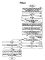
- FIG. 3 shows an automatic ID registration process performed by tire pressure monitoring controller 5 according to the first embodiment, for registering the tire ID code of each tire. (A flowchart of FIG. 3 corresponds to a tire identification code registering means.)
- controller 5 reads a predetermined single data set reception level threshold t, and a predetermined single transmission data unit (consecutive eight data sets) accumulated level threshold T. After S1, controller 5 proceeds to a next step S2.
- controller 5 resets each of a first ID count M for already-memorized IDs (S11) and a second ID count N for not-yet-memorized IDs (S16), to zero as initial value. Thereafter, controller 5 proceeds to S3 to check a vehicle main switch which, in this example, is an ignition switch of the vehicle.
- controller 5 examines whether the vehicle speed is higher than or equal to a predetermined speed.
- the predetermined speed is 40km/h.
- controller 5 proceeds from S4 to S5 on the assumption that the system is in a state capable of receiving data.
- controller 5 returns to S3.
- controller 5 checks data received by the receiving section, and ascertains an ID of wireless reception signal and a reception level an of the reception signal. Thereafter, controller 5 proceeds to S6.
- Step S5 corresponds to a reception level measuring means for measuring the reception level of a received wireless signal.
- the reception level an is a single data set reception level for each data set.
- controller 5 calculates a single data set reception level difference (an-t) which is a difference between the measured single data set reception level an and the reception level threshold t (obtained at S1); and then proceeds to S7.
- Step S6 corresponds to a single data set reception level difference calculating means.
- controller 5 calculates an accumulated value An of a predetermined number of single data reception level differences.
- Each single transmission data unit is a series of data sets transmitted consecutively in a single transmission operation.
- the accumulated value An is a sum of eight single data set reception level differences of eight data sets received consecutively. (Step S7 corresponds to an accumulated value calculating means.)
- controller 5 proceeds to S8.
- controller 5 compares the accumulated value An with the accumulated data reception level threshold T obtained at S1, to determine whether An is greater than T.
- the accumulated data reception level threshold T is equal to 50 dB ⁇ V, for example.
- controller 5 considers that the distance between the receiver unit and transmitter unit is not short enough, and proceeds to S9.
- controller 5 discards the received data since the spatial relationship between the transmitter unit and receiver unit is not a proximate relationship.
- An>T controller 5 considers that the receiver unit is in proximity with the transmitter unit, and proceeds to S10.
- controller 5 examines whether ID of the received data is identical to ID stored previously. From S10, controller 5 proceeds to S11 when there is one identical ID already stored, and to S16 when ID of the received data is different from the stored IDs.
- controller 5 increments (increases by one) the count M for the already-memorized ID, and then proceeds to S12.
- controller 5 stores the accumulated value Anm (An1, An2, An3, An4) in RAM 5f, and then proceeds to S13.
- controller 5 checks an elapsed time te from the start of the operation of storing the accumulated values Anm in RAM 5f, and determines whether the elapsed time te becomes equal to a predetermined time length (which, in this example, is 3 minutes). From S13, controller 5 returns to S4 in the case of NO, and proceeds to S14 in the case of YES. It is optional to employ a predetermined number of data transmitting operations instead of the predetermined time length (3 min). For example, the predetermined number of data transmitting operations is three. In this case, a tire identification code is registered when the total of accumulated values Anm accumulated within three times of data receptions is greatest.
- controller 5 calculates a total of accumulated values for each IDn (ID1, ID2, ID3, ID4, ID5), and then proceeds to S15.
- controller 5 registers, in EEPROM 5c, IDn of the maximum value among the sums of the accumulated values Anm. (In an example shown in FIG. 6 , ID2 is registered.)
- controller 5 increments the count N for different Ids, and then proceeds to S17.
- controller 5 stores IDn and the accumulated value Anm (An1, An2, An3, An4) in RAM 5f, and then returns to S4.
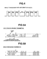
- FIG. 4 shows one transmission data unit which is data transmitted as a unit in one transmitting operation from one of transmitter units T1 ⁇ T4.
- a single transmission data unit of this example is composed of eight transmission data sets transmitted consecutively at irregular transmission intervals.
- seven intervals between adjacent two of the eight data sets are: 4sec, 4sec, 6sec, 8sec, 6sec, 6sec,and 4sec, as shown in FIG. 4 .
- each of transmission data sets contains at least a start bit, a function code, ID, pressure data, and check sum.
- FIGS. 5A and 5B show transmission data from transmitters T1 ⁇ T4.
- FIG. 5B shows transmission data received by one receiver unit from the transmitter at the nearest position.
- FIG. 5A shows transmission data from a wheel of another vehicle, or a wheel of the vehicle at another (non-nearest) position.
- the tire pressure monitoring system is operated as follows:
- the second receiver unit R2 receives data as shown in FIG. 5A .
- the reception level is lower; the difference (an-t) is smaller than zero or close to zero, and the accumulated value An of the differences (an-t) for eight consecutive data sets becomes a small positive value or a negative value.
- controller 5 reaches step S8 by the flow of S1 ⁇ S2 ⁇ S3 ⁇ S4 ⁇ S5 ⁇ S6 ⁇ S7 ⁇ S8; and further proceeds to S9 when the accumulated value An is smaller than or equal to accumulated level threshold T.
- controller 5 destroys data for which An ⁇ T.
- controller 5 reaches step S8 by the flow of S1 ⁇ S2 ⁇ S3 ⁇ S4 ⁇ S5 ⁇ S6 ⁇ S7 ⁇ S8; and further proceeds to S10, S11 and S12 when the accumulated value An is greater than accumulated level threshold T.
- the accumulated value Anm is stored in RAM 5f.
- the tire pressure monitoring system repeats the flow of S1 ⁇ S2 ⁇ S3 ⁇ S4 ⁇ S5 ⁇ S6 ⁇ S7 ⁇ S8 ⁇ S10 ⁇ S11 ⁇ S12 until the expiration of the predetermined time (3 min).
- controller 5 collects tire identification codes IDn and accumulated values Anm in RAM 5f.
- the number of accumulated values of transmission data received from transmitter units at remote positions from the second receiver unit R2 tends to be smaller.
- RAM 5f stores accumulated values A11, A12, and A13 for tire identification code ID1 of front left wheel 1; A21, A22, A23, and A24 for tire identification code ID2 of front right wheel 2; A31 and A32 for tire identification code ID3 of rear left wheel 3; A41, A42,and A43 for tire identification code ID4 of rear right wheel 4; and A51 for the identification code ID5 of a spare tire in the vehicle.
- the monitoring system automatically registers the tire identification code ID2 of transmission data received by second receiver unit R2 from second transmitter unit T2 as the tire identification code for front right wheel 2.
- the thus-constructed tire pressure monitoring system measures the strengths of radio waves of the wireless signals received by receiver units R1 ⁇ R4, and registers an ID code by comparing the strengths of radio waves of the wireless signals. Therefore, the tire pressure monitoring system can register tire identification codes accurately for four wheels at the four positions of a vehicle, and eliminate the need for troublesome tire pressure setting operations in the case of tire replacement or tire rotation.
- the tire pressure monitoring system can register the tire identification code accurately when the battery voltages of the transmitter units T1 ⁇ T4 are substantially uniform.
- the battery voltages are uniform among transmitter units when a tire is not replaced (a transmitter unit is not replaced, that is), when tires are rotated in a vehicle, and when batteries of transmitter units T1 ⁇ T4 are all replaced simultaneously.
- step 55 for measurement of reception levels S6 for calculation of reception level difference, S7 for calculation of accumulated value and S8 for comparison of accumulated value An with T, the tire pressure monitoring system can improve the reliability of ID registration even if there is transmission loss or reception loss in part of data.
- the tire pressure monitoring system temporality stores tire identification codes IDn and accumulated values Anm, and registers the tire identification code corresponding to the greatest sum of accumulated values (at S15). Therefore, the tire pressure monitoring system can register ID accurately by using the temporality stored data without being adversely influenced by another nearby vehicle having a similar transmitter for tire pressure monitoring.
- FIG. 7 shows an automatic tire ID registering process according to a second embodiment of the present invention.
- the second embodiment is designed to register tire identification codes accurately even when a tire is replaced by a new tire including a transmitter unit of a higher battery voltage.
- a tire pressure monitoring system according to the second embodiment is substantially identical in construction to the system of the first embodiment shown in FIGS. 1 and 2 .
- transmitter units T1 ⁇ T4 are referred to as transmitters ID1 ⁇ ID4 and a transmitter unit of a new tire is referred to as transmitter IDS.
- Steps S1 ⁇ S17 are substantially identical to S1 ⁇ S17 of FIG. 3 .
- FIG. 7 corresponds to the tire identification code registering means.
- controller 5 checks whether one ID (ID5 in an example of FIG. 9 ) is to be registered at different tire positions as the result of step S15 for the greatest sum (total) of Anm values. From S18, controller 5 proceeds to S19 in the case of YES, and ends the process in the case of NO.
- controller 5 compares the strengths of radio waves received by receiver units R1 ⁇ R4 from the transmitter of the identification code (ID5) to be registered at the different tire positions; and then proceeds to S20.
- controller 5 selects the receiver unit (R1 in the example of FIG. 9 ) which received the radio waves of the greatest strength among receiver units R1 ⁇ R4 from the transmitter (ID5), and registers the identification code of the transmitter (ID5) as one at the location of the selected receiver unit. After S20, controller 5 proceeds to S21.
- controller 5 compares the strengths of waves received from the transmitter units (ID2, ID3, and ID4 in the example of FIG. 9 ) excluding the transmitter (ID5) whose ID is registered; and registers the transmitter's ID of the greatest wave strength as the transmitter at the location of each remaining receiver unit (R2, R3,or R4).
- controller 5 proceeds from S15 through S18 to END of the program. Therefore, the monitoring system registers, in EEPROM 5c, IDn of the greatest sum (total) of accumulated values Anm for each IDn.
- the monitoring system selects transmitter ID1 of a greatest value of 50 dB ⁇ V for first receiver unit R1; transmitter ID2 of a greatest value of 50 dB ⁇ V for second receiver unit R2; transmitter ID3 of a greatest value of 50 dB ⁇ V for third receiver unit R3; and transmitter ID4 of a greatest value of 50 dB ⁇ V for fourth receiver unit R4.
- transmitter ID1 When transmitter ID1 is replaced by transmitter IDS, for example, as shown in FIG. 9 , new transmitter ID5 is higher in battery voltage than the remaining transmitters ID2 ⁇ ID4, and hence the radio wave strength from transmitter ID 5 is higher.
- the monitoring system selects the new transmitter ID5 for all the receiver units R1 ⁇ R4 since the wave strength of radio waves from new transmitter ID5 is greatest in each of receiver units R1 ⁇ R4.
- the monitoring system follows the route of S15 ⁇ S18 ⁇ S19 ⁇ S20 ⁇ S21 since ID5 is to be registered at different tire positions (all the four tire positions in the example of FIG. 9 ).
- the monitoring system pays attention to transmitter ID5; compares the signal strengths of transmitter ID5 at receiver units R1 ⁇ R4; and registers transmitter ID5 at the tire position (front left position) corresponding to the receiver unit R1 receiving the signal of a greatest strength of 70 dB ⁇ V.
- the monitoring system compares the signal strengths of the remaining transmitters ID2, ID3, and ID4 for each of the remaining receiver units R2, R3, and R4, and select the transmitter of the greatest signal strength for each remaining receiver unit.
- the tire pressure monitoring system performs the wave strength comparison among the receiver units for one transmitter instead of the comparison among the transmitters for each receiver unit; and thereby correctly concludes that the new transmitter ID5 is located at the position adjacent to the first receiver unit R1 at the front left tire position.
- the new transmitter ID5 is located at the position adjacent to the first receiver unit R1 at the front left tire position.
- the monitoring system can select transmitter ID2 for receiver unit R2 by comparing the output values from the remaining transmitters ID2, ID3,and ID4; select transmitter ID3 for receiver unit R3 by comparing the output values from the remaining transmitters ID2, ID3,and ID4; and select transmitter ID4 for receiver unit R4 by comparing the output values from the remaining transmitters ID2, 103, and ID4.
- the second embodiment can register identification codes accurately even if a tire is replaced by a new tire equipped with a transmitter having a higher battery voltage.
- FIG. 10 shows an automatic tire ID registering process according to a third embodiment of the present invention.
- the third embodiment is designed to register tire identification codes accurately without regard to battery voltages of transmitters.
- a tire pressure monitoring system according to the second embodiment is substantially identical in construction to the system of the first embodiment shown in FIGS. 1 and 2 .
- Steps S1 ⁇ S13, S16 and S17 are substantially identical to S1 ⁇ S13, S16 and S17 of Fig. 3 .
- controller 5 compares signal strengths of wireless signals received by receiver units R1 ⁇ R4 from each transmitter; and then proceeds to step S23.
- controller 5 registers ID of each transmitter at the tire position corresponding to the receiver unit receiving the greatest signal strength, in EEPROM 5c.
- the tire pressure monitoring system is arranged to select one of receiver units for each transmitter by comparing the signal strengths.
- the monitoring system selects receiver unit R1 for transmitter ID5 by comparing signal strengths of 70, 65, 60,and 65 at R1, R2, R3, and R4 with one another; selects receiver unit R2 for transmitter ID2 by comparing signal strengths of 45, 50, 45, and 40 at R1, R2, R3, and R4 with one another; selects receiver unit R3 for transmitter ID3 by comparing signal strengths of 40, 45, 50,and 45 at R1, R2, R3, and R4 with one another; and selects receiver unit R4 for transmitter ID4 by comparing signal strengths of 45, 40, 45, and 50 at R1, R2, R3, and R4 with one another.
- the monitoring system can register tire identification codes accurately without being adversely influenced by the nonuniformity in battery voltage among transmitters.
- the thus-constructed tire pressure monitoring system When a plurality of wireless signals are received, the thus-constructed tire pressure monitoring system according to the third embodiment like the first embodiment measures the strengths of radio waves of the wireless signals received by receiver units R1 ⁇ R4, and registers an ID code by comparing the strengths of radio waves of the wireless signals. Therefore, the tire pressure monitoring system can register tire identification codes accurately for four wheels at the four positions of a vehicle, and eliminate the need for troublesome tire pressure setting operations in the case of tire replacement or tire rotation.
- the monitoring system according to the third embodiment can register identification codes accurately without regard to battery voltages of transmitter.
- FIG. 11 shows an automatic tire ID registering process according to a fourth embodiment of the present invention.
- the fourth embodiment is designed to register tire identification codes accurately even when a vehicle comes close to another vehicle having transmitters in tires.
- a tire pressure monitoring system according to the fourth embodiment is substantially identical in construction to the system of the first embodiment shown in FIGS. 1 and 2 .
- controller 5 preliminarily stores a radio wave output value map (database) of a transmitter provided in each of tires 1, 2, 3, and 4 at front left position FL, front right position FR, rear left position RL and rear right position RR; and clear a memory area for temporarily storing (external) identification codes of neighboring vehicles. Then, controller 5 proceeds to step S42.
- database radio wave output value map
- controller 5 examiners whether an ignition switch of the vehicle is ON and at the same time the vehicle speed is higher than or equal to a predetermined speed (5 km/h). From S42, controller 5 proceeds to S43 in the case of YES, and returns to S41 in the case of NO without entering the ID registering mode.
- the condition of S42 is a condition excluding situations of tire rotation and replacement of transmitters.
- controller 5 receives data A from each transmitter, and proceeds to S45.
- controller 5 examiners whether ID of the received data A is identical to ID stored (as external ID) in the memory area for identification codes of neighboring vehicles. In the case of YES, controller 5 proceeds to S50, and discards the received data A. In the case of NO, controller 5 proceeds from S45 to S46.
- controller 5 selects the position of receiver unit of a greatest signal strength among the receiver units, and selects the output value map on the assumption that ID of the data A currently being received is from the selected position. After S46, controller 5 proceeds to S47.
- controller 5 examines whether all the output values (radio wave strength levels) from the transmitter received by the receiver units are within the range of the output value map selected at S46. From S47, controller 5 proceeds to S51 in the case of YES, and to S48 in the case of NO.
- controller 5 considers that the data A is from another vehicle, discards the data A, and then proceeds to S49.
- controller 5 stores ID of the data A as external ID from another vehicle, and returns to S42. Once ID is stored as external ID of another vehicle, ID is excluded from ID registration during vehicle running operation.
- controller 5 regards the tire position selected at S46 as an ID registration candidate position because all the output values (radio wave strength levels) from the transmitter received by the receiver units are within the range of the output value map selected at S46. From S51, controller 5 proceeds to S52.
- controller 5 completes the registration of ID at that tire position since that tire position is selected twice as the candidate, and then proceeds to S55.
- controller 5 examines whether the ID registration is completed for all the four wheels. Controller 5 ends this registration process in the case of YES, and returns to S42 in the case of NO.
- the tire pressure monitoring system according to the fourth embodiment provided in the first vehicle operates as follows.
- the tire pressure monitoring system of the first vehicle might register ID5 of the second vehicle as ID of the rear left tire of the first vehicle. To avoid such erroneous registration, it is necessary to set a long time such as 10 minutes for comparison of wireless signal strengths before registration in the case of the first embodiment in consideration of time for the second vehicle to move apart from the first vehicle.
- the tire pressure monitoring system takes the route of S41 ⁇ S42 ⁇ S43 ⁇ S44 ⁇ S45 ⁇ S46, and selects, at S46, the output value map (as shown by broken lines in FIG. 13 ) for the rear left position because the signal strength of ID5 of the second vehicle is greatest.
- controller 5 takes the route of S46 ⁇ S47 ⁇ S48 ⁇ S49. Data A from another vehicle is destroyed at S48 and ID of another vehicle is registered as external ID of neighboring vehicles at S49 for next check at S45.
- the output of transmitter ID3 is within the tolerance range of the rear left position, and hence the flow is S46 ⁇ S47 ⁇ S51 ⁇ S52 ⁇ S53 ⁇ S42.
- the monitoring system follows the course of S53 ⁇ S54 ⁇ S55 ⁇ S42 until ID registration is finished for all the four wheels.
- the tire pressure monitoring system according to the fourth embodiment can avoid undesired influence from neighboring vehicles equipped with similar tire pressure monitoring transmitters.
- the output characteristic map from each transmitter unit (ID3 at the rear left tire position, for example) is prepared in the form of a four-quadrant map, from wave strengths of radio waves received from the transmitter unit by the four receiver units.
- the positional relationship of each transmitter unit with respect to the four receiver units in the same vehicle is approximately fixed invariable, and the fourth embodiment discriminates transmitters of its own vehicle from transmitters of another vehicle by using this stable positional relationship.
- the thus-constructed tire pressure monitoring system When a plurality of wireless signals are received, the thus-constructed tire pressure monitoring system according to the fourth embodiment like the first embodiment measures the strengths of radio waves of the wireless signals received by receiver units R1 ⁇ R4, and registers an identification code by comparing the strengths of radio waves of the wireless signals. Therefore, the tire pressure monitoring system can register tire identification codes accurately for four wheels at the four positions of a vehicle, and eliminate the need for troublesome tire pressure setting operations in the case of tire replacement or tire rotation.
- the tire pressure monitoring system according to the fourth embodiment can register identification codes accurately even if wireless signals are received from a vehicle nearby equipped with similar tire pressure monitoring transmitters.
- FIGS. 15 and 16 show a tire pressure monitoring process according to a fifth embodiment of the present invention.
- a tire pressure monitoring system according to the fifth embodiment is substantially identical in construction to the system shown in FIGS. 1 , 2 and 4 .
- FIG. 14 shows a transmission data set transmitted from each of four tire pressure sensing (or monitoring)(unregistered) transmitters A ⁇ B which can be used as transmitter units T1 ⁇ T4.
- one transmission data set is composed of at least a start bit, a function code, ID, pressure data, check sum, and a portion of field strength, as shown in FIG. 14 .
- Each transmission data set is contained within a time length of 15.3 msec.
- FIG. 15 is a flowchart showing a tire position determining process according to the fifth embodiment. By this process, the monitoring system determines the position of each tire. ( FIG, 15 corresponds to a tire position determining means.)
- tire pressure monitoring or sensing transmitter A of a vehicle transmits data.
- receiver units R1 ⁇ R4 receive the data.
- the tire pressure monitoring system determines the magnitude of field strength at each of receiver units R1 ⁇ R4 (as shown in a field strength determining subroutine of FIG. 16 ).
- the system determines the receiver unit which receives a wireless signal of a greatest field strength.
- the system proceeds from S204, to S207 and S208, and concludes that the tire pressure monitoring transmitter A currently being examined is located at the position of the front right wheel adjacent to receiver unit R2.
- the tire pressure monitoring system receives data transmitted from each of the remaining tire pressure monitoring transmitter B ⁇ D, and determines the position of each of the transmitter B, C, and D in the same manner.
- the tire pressure monitoring system compares the signal strengths or field strengths received at each tire position in the subsequent ID registration mode and register the identification code received with a greatest field strength as ID at that tire position, in EEPROM 5c.
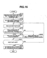
- FIG. 16 shows a field strength determining subroutine of step S203 in FIG. 16 .
- the tire pressure monitoring system receives a first data set with one receiver unit from one transmitter.
- the monitoring system records a field strength of the received data set.
- the monitoring system receives a second (next) data set.
- the monitoring system compares the field strength of the first data set and the field strength of the second data set and determines whether the field strength of the second data set is greater than the already-recorded field strength of the first data set. From S218, the monitoring system proceeds to S219 in the case of YES, and to S220 in the case of NO.
- the monitoring system When the field strength of the next data set is greater than the field strength of the first data set, the monitoring system replaces the already-recorded field strength with a new entry of the field strength of the second data set at S219. When the field strength of the next data set is smaller than or equal to the field strength of the first data set, the monitoring system holds the already-recorded field strength unchanged, at S220.
- the monitoring system examines where there is a next data set. In the case of YES, the system returns to S217, and repeats the program section of S217, S218, S219, and S221. When the eight data sets of one transmission data unit are all received, the monitoring system proceeds from S221 to step S222, and determine the field strength of the transmission data unit by employing the recorded field strength as a greatest field strength.
- first receiver unit R1 When first receiver unit R1 receives data from four tire pressure sensing transmitter units A, B, C, and D, the field strength of reception from transmitter unit A is greatest, and the flow is S201 ⁇ S202 ⁇ S203 ⁇ S204 ⁇ S205 ⁇ S206. At S206, the system concludes the position of transmitter unit A to be the front left wheel position of receiver unit R1.
- second receiver unit R2 When second receiver unit R2 receives data from four tire pressure sensing transmitter units A, B, C, and D, the field strength of reception from transmitter unit B is greatest, and the flow is S201 ⁇ S202 ⁇ S203 ⁇ S204 ⁇ S207 ⁇ S208. At S208, the system concludes the position of transmitter unit B to be the front right wheel position of receiver unit R2.
- third receiver unit R3 receives data from four tire pressure sensing transmitter units A, B, C,and D, the field strength of reception from transmitter unit C is greatest, and the flow is S201 ⁇ S202 ⁇ S203 ⁇ S204 ⁇ S209 ⁇ S210. At S210, the system concludes the position of transmitter unit C to be the rear left wheel position of receiver unit R3.
- receiver unit R4 When fourth receiver unit R4 receives data from four tire pressure sensing transmitter units A, B, C, and D, the field strength of reception from transmitter unit D is greatest, and the flow is S201 ⁇ S202 ⁇ S203 ⁇ S204 ⁇ S211 ⁇ S212. At S212, the system concludes the position of transmitter unit D to be the rear right wheel position of receiver unit R4.
- the thus-constructed tire pressure monitoring system compares the field strengths of radio waves, determines the tire position by determining the receiver unit of the greatest field strength. Therefore, the tire pressure monitoring system can register tire identification codes accurately for four wheels at the four positions of a vehicle, and eliminate the need for troublesome tire pressure setting operations in the case of tire replacement or tire rotation.
- the field strength is determined by checking field strengths of a plurality of data sets as shown in the subroutine of FIG. 16 . Therefore, the monitoring system can determine the field strength of each wireless signal properly and improve the accuracy of registration.
Landscapes
- Engineering & Computer Science (AREA)
- Mechanical Engineering (AREA)
- Computer Networks & Wireless Communication (AREA)
- Measuring Fluid Pressure (AREA)
- Arrangements For Transmission Of Measured Signals (AREA)
Claims (12)
- Reifendruck-Überwachungsvorrichtung, Folgendes umfassend:eine Vielzahl von Sendereinheiten (T1 ~ T4), für jeweilige Reifen (1 ~ 4) eines Fahrzeugs bereitgestellt, wobei jede der Sendereinheiten einen Drucksensor (10a) einschließt, um einen Reifendruck des entsprechenden der Reifen abzutasten, um einen abgetasteten Reifendruck zu bestimmen, und eine Sendeeinrichtung (10e) zum Senden eines drahtlosen Signals, um Information über den abgetasteten Reifendruck und einen Reifenidentifikationscode zum Identifizieren des entsprechenden der Reifen zu übermitteln;einen Empfangsabschnitt (R1 ~ R4), im Fahrzeug bereitgestellt und dazu angeordnet, die drahtlosen Signale von den Sendereinheiten zu empfangen, wobei der Empfangsabschnitt eine Vielzahl von Empfängereinheiten einschließt, deren jede in der Nähe eines eindeutigen der Reifen des Fahrzeugs bereitgestellt ist; undeinen Controller (5), um den Reifenidentifikationscode eines jeden Reifens zu registrieren, wobei der Controller konfiguriert ist:Signalstärken von drahtlosen Signalen zu messen, wenn die drahtlosen Signale durch den Empfangsabschnitt empfangen werden; undden Reifenidentifikationscode eines jeden Reifens durch Vergleichen der Signalstärken zu registrieren,dadurch gekennzeichnet, dass der Controller (5) dazu konfiguriert ist, die Signalstärken der drahtlosen Signale zu messen, deren jedes eine Vielzahl von aufeinanderfolgenden Datensätzen einschließt, und, falls ein Reifenidentifikationscode von einer Sendereinheit zur Registration an einer Vielzahl von Reifenpositionen ausgewählt wird, der Controller a) die Sendereinheit als eine Ausnahmesendereinheit ansieht, b) den von der Ausnahmesendereinheit empfangenen Reifenidentifikationscode registriert, indem er die Signalstärken von drahtlosen Signalen vergleicht, die von der Ausnahmesendereinheit durch die Empfängereinheiten empfangenen werden; und c) die Reifenidentifikationscodes registriert, die von den Sendereinheiten empfangen werden, die von der Ausnahmesendereinheit verschieden sind, indem er die Signalstärken von drahtlosen Signalen vergleicht, die durch jede Empfängereinheit von den Sendereinheiten empfangen werden, die von der Ausnahmesendereinheit verschieden sind.
- Reifendruck-Überwachungsvorrichtung nach Anspruch 1, worin, wenn eine Vielzahl von Empfängereinheiten drahtlose Signale empfangen, die einen nichtregistrierten Reifenidentifikationscode enthalten, der Controller Stärken von Funkwellen vergleicht, die durch die Empfängereinheiten als die den nichtregistrierten Reifenidentifikationscode enthaltenden drahtlosen Signale empfangen werden, und den nichtregistrierten Reifenidentifikationscode an einer Reifenposition der Empfängereinheit registriert, die das den nichtregistrierten Reifenidentifikationscode enthaltende drahtlose Signal mit einer größten Funkwellenstärke empfängt.
- Reifendruck-Überwachungsvorrichtung nach Anspruch 1 oder 2, worin der Controller konfiguriert ist zum:Messen eines Empfangslevels (an) eines jeden von Datensätzen, die in einem drahtlosen Signal enthalten sind, das durch eine der Empfängereinheiten empfangen wird;Berechnen einer Leveldifferenz (an-t) eines jeden Datensatzes zwischen dem Empfangslevel und einer vorgegebenen Levelschwelle;Berechnen einer Summe (An) der Leveldifferenzen der Datensätze;Prüfen, ob die Summe der Leveldifferenzen größer ist als eine vorgegeben Summenschwelle (T); undRegistrieren des Reifenidentifikationscodes des drahtlosen Signals, wenn die Summe der Leveldifferenzen größer ist als die vorgegebene Summenschwelle.
- Reifendruck-Überwachungsvorrichtung nach Anspruch 3, worin jede der Sendereinheiten dazu konfiguriert ist, ein drahtloses Signal zu erzeugen, das eine Vielzahl von aufeinanderfolgenden Datensätzen enthält; und der Controller konfiguriert ist zum:Berechnen der Summe der Leveldifferenzen von aufeinanderfolgenden Datensätzen in jedem von drahtlosen Signalen, die durch eine der Empfängereinheiten empfangen werden;vorübergehendes Speichern einer jeden der Summen, wenn die Summe größer ist als die vorgegebene Summenschwelle;Berechnen einer Gesamtsumme der Summen für jeden Reifenidentifikationscode durch Addieren der Summen für jeden vorübergehend gespeicherten Reifenidentifikationscode; undRegistrieren des Reifenidentifikationscodes, für den die Gesamtsumme der Summen von Leveldifferenzen am größten ist.
- Reifendruck-Überwachungsvorrichtung nach Anspruch 4, worin der Controller dazu konfiguriert ist, jede der Summen in einem Speicherabschnitt zu speichern, wenn die Summe größer ist als die vorgegebene Summenschwelle, und Datensätze eines drahtlosen Signals auszulassen, falls die Summe der Leveldifferenzen des drahtlosen Signals kleiner oder gleich der vorgegebenen Summenschwelle ist.
- Reifendruck-Überwachungsvorrichtung nach Anspruch 4, worin der Controller dazu konfiguriert ist, in einem Speicherabschnitt die Summen der Leveldifferenzen von drahtlosen Signalen zu akkumulieren, die während eines Intervalls empfangen werden, das durch eine einer vorgegebene Zeitlänge und einer vorgegeben Anzahl von Datenempfangsoperationen definiert ist.
- Reifendruck-Überwachungsvorrichtung nach Anspruch 1, worin der Controller dazu konfiguriert ist, die Signalstärken von drahtlosen Signalen zu vergleichen, die durch die Empfängereinheiten von einer der Sendereinheiten empfangen werden, und einen Reifenidentifikationscode zu registrieren, der durch die Sendereinheit an einer Reifenposition der Empfängereinheit gesendet wird, an der die Signalstärke am größten ist.
- Reifendruck-Überwachungsvorrichtung nach Anspruch 1, worin der Controller dazu konfiguriert ist, eine Signalempfangslevelabbildung einer jeden der Sendereinheiten zu speichern und einen Reifenidentifikationscode zu registrieren, der durch die Empfängereinheiten empfangen wird, indem die Signalstärken von drahtlosen Signalen verglichen werden, die durch die Empfängereinheiten mit Bezug auf die Signalempfangslevelabbildung empfangen werden.
- Reifendruck-Überwachungsvorrichtung nach Anspruch 1 oder 2, worin der Controller dazu konfiguriert ist, die Signalstärken von drahtlosen Signalen zu vergleichen, die durch eine Empfängereinheit von den Sendereinheiten empfangen werden, und einen Reifenidentifikationscode des Senders einer größten Signalstärke an einer Reifenposition der Empfängereinheit zu registrieren.
- Reifendruck-Überwachungsvorrichtung nach Anspruch 1 oder 2, worin jede der Sendereinheiten dazu konfiguriert ist, ein drahtloses Signals zu erzeugen, das eine Vielzahl von aufeinanderfolgenden Datensätzen enthält; und der Controller dazu konfiguriert ist, die Signalstärke eines jeden drahtlosen Signals als Funktion einer größten der Signalstärken der Datensätze zu bestimmen.
- Reifendruck-Überwachungsprozess, Folgendes umfassend:Empfangen von drahtlosen Signalen an einer Vielzahl von Positionen in unmittelbarer Reifennähe in einem Fahrzeug von Sendereinheiten, die jeweils für Reifen des Fahrzeugs bereitgestellt werden, um einen Reifendruck des entsprechenden einen der Reifen abzutasten, um einen abgetasteten Reifendruck zu bestimmen, und ein drahtloses Signal zu senden, um Information über den abgetasteten Reifendruck zu übermitteln und einen Reifenidentifikationscode zu übermitteln, um den entsprechenden der Reifen zu identifizieren;Messen von Signalstärken der drahtlosen Signale, die an den Positionen in unmittelbarer Reifennähe empfangen werden; undRegistrieren des Reifenidentifikationscodes eines jeden Reifens durch Vergleichen der Signalstärken,dadurch gekennzeichnet, dass das drahtlose Signal, das von jeder Sendereinheit gesendet wird, eine Vielzahl von aufeinanderfolgenden Datensätzen einschließt, und die Signalstärke eines jeden drahtlosen Signals von den aufeinanderfolgenden Datensätzen gemessen wird, worin, falls ein Reifenidentifikationscode von einer Sendereinheit zur Registration an einer Vielzahl von Reifenpositionen ausgewählt wird, der Controller die Sendereinheit als eine Ausnahmesendereinheit ansieht; den Reifenidentifikationscode registriert, der von der Ausnahmesendereinheit empfangen wird, indem die Signalstärken von drahtlosen Signalen verglichen werden, die von der Ausnahmesendereinheit durch die Empfängereinheiten empfangen werden; und die Reifenidentifikationscodes registriert, die von den Sendereinheiten empfangen werden, die von der Ausnahmesendereinheit verschieden sind, indem die Signalstärken von drahtlosen Signalen verglichen werden, die durch jede Empfängereinheit von den Sendereinheiten empfangen werden, die von der Ausnahmesendereinheit verschieden sind.
- Prozess nach Anspruch 11, der unter Verwendung der Vorrichtung nach einem der Ansprüche 1 bis 10 ausgeführt wird.
Applications Claiming Priority (6)
| Application Number | Priority Date | Filing Date | Title |
|---|---|---|---|
| JP2003013541A JP3952956B2 (ja) | 2003-01-22 | 2003-01-22 | タイヤ空気圧モニター装置 |
| JP2003013541 | 2003-01-22 | ||
| JP2003067695 | 2003-03-13 | ||
| JP2003067695 | 2003-03-13 | ||
| JP2003309773 | 2003-09-02 | ||
| JP2003309773A JP4059171B2 (ja) | 2003-03-13 | 2003-09-02 | タイヤ空気圧モニター装置 |
Publications (3)
| Publication Number | Publication Date |
|---|---|
| EP1440824A2 EP1440824A2 (de) | 2004-07-28 |
| EP1440824A3 EP1440824A3 (de) | 2008-09-10 |
| EP1440824B1 true EP1440824B1 (de) | 2014-09-10 |
Family
ID=32600738
Family Applications (1)
| Application Number | Title | Priority Date | Filing Date |
|---|---|---|---|
| EP04250307.8A Expired - Lifetime EP1440824B1 (de) | 2003-01-22 | 2004-01-21 | Reifendrucküberwachungssystem und Verfahren |
Country Status (3)
| Country | Link |
|---|---|
| US (1) | US6941803B2 (de) |
| EP (1) | EP1440824B1 (de) |
| CN (1) | CN1298555C (de) |
Families Citing this family (55)
| Publication number | Priority date | Publication date | Assignee | Title |
|---|---|---|---|---|
| JP2005100100A (ja) * | 2003-09-25 | 2005-04-14 | Toyota Motor Corp | 車輪情報処理装置および車輪情報処理方法 |
| JP2005181064A (ja) * | 2003-12-18 | 2005-07-07 | Denso Corp | タイヤ空気圧検出装置 |
| CN100342409C (zh) * | 2005-01-21 | 2007-10-10 | 何崇中 | 具有节电模式的tpms射频发射器 |
| JP4341559B2 (ja) * | 2005-01-26 | 2009-10-07 | トヨタ自動車株式会社 | 車輪情報処理装置 |
| JP4175348B2 (ja) * | 2005-07-06 | 2008-11-05 | 株式会社デンソー | 車輪位置検出装置およびそれを備えたタイヤ空気圧検出装置 |
| US20070038346A1 (en) * | 2005-08-11 | 2007-02-15 | Wabash National, L.P. | System and method of wireless communication between a trailer and a tractor |
| JP4812432B2 (ja) * | 2006-01-10 | 2011-11-09 | 株式会社ブリヂストン | タイヤ点検装置、タイヤ点検システム及びタイヤ点検方法 |
| US20070194896A1 (en) * | 2006-02-17 | 2007-08-23 | Wabash National, L.P. | Wireless tire status monitor and monitoring system |
| JP2007320423A (ja) * | 2006-05-31 | 2007-12-13 | Nec Electronics Corp | タイヤ位置検出システム |
| JP4752661B2 (ja) * | 2006-08-01 | 2011-08-17 | 株式会社デンソー | 送信機およびそれを備えたタイヤ空気圧検出装置 |
| JP4858034B2 (ja) | 2006-09-19 | 2012-01-18 | 株式会社デンソー | 車輪位置検出装置およびそれを備えたタイヤ空気圧検出装置 |
| JP4876907B2 (ja) * | 2006-12-26 | 2012-02-15 | 株式会社デンソー | 車輪位置検出装置、それを備えたタイヤ空気圧検出装置および送受信機 |
| US20080205553A1 (en) * | 2007-02-27 | 2008-08-28 | Continental Automotive Systems Us, Inc. | Reconstruction of tire pressure monitoring signals |
| CN101687447B (zh) | 2007-07-03 | 2015-02-11 | 欧陆汽车系统美国有限公司 | 通用轮胎压力监测传感器 |
| DE102008005317B4 (de) * | 2008-01-21 | 2018-07-12 | Robert Bosch Gmbh | Verfahren zur Konfiguration eines ultraschallbasierten Fahrerassistenzsystems und korrespondierender Ultraschallsensor |
| JP4709293B2 (ja) * | 2009-04-08 | 2011-06-22 | 株式会社豊田中央研究所 | タイヤ情報監視装置 |
| CN102052990B (zh) * | 2009-12-23 | 2015-01-07 | 奇瑞汽车股份有限公司 | 一种tpms性能测试装置和测试方法 |
| CN102452279B (zh) * | 2010-10-22 | 2015-07-15 | 上海保隆汽车科技股份有限公司 | 轮胎压力信号接收和处理方法及其装置 |
| JP5569693B2 (ja) * | 2010-11-30 | 2014-08-13 | 横浜ゴム株式会社 | タイヤ状態監視システム及び装着位置特定方法 |
| US8751092B2 (en) | 2011-01-13 | 2014-06-10 | Continental Automotive Systems, Inc. | Protocol protection |
| DE102011008881B4 (de) * | 2011-01-19 | 2014-09-25 | Deutsches Zentrum für Luft- und Raumfahrt e.V. | Verfahren und Vorrichtung zur Erfassung eines vorausfahrenden Kraftfahrzeuges |
| US9676238B2 (en) | 2011-08-09 | 2017-06-13 | Continental Automotive Systems, Inc. | Tire pressure monitor system apparatus and method |
| CN103826879B (zh) * | 2011-08-09 | 2017-10-10 | 大陆汽车系统公司 | 用于传输轮胎压力信号的设备和方法 |
| US9024743B2 (en) | 2011-08-09 | 2015-05-05 | Continental Automotive System, Inc. | Apparatus and method for activating a localization process for a tire pressure monitor |
| KR101599780B1 (ko) | 2011-08-09 | 2016-03-04 | 컨티넨탈 오토모티브 시스템즈 인코포레이티드 | 타이어 압력 모니터링 시스템을 위한 프로토콜 오해 회피 장치 및 방법 |
| WO2013022435A1 (en) | 2011-08-09 | 2013-02-14 | Continental Automotive Systems, Inc. | Tire pressure monitoring apparatus and method |
| CN103101408A (zh) * | 2011-11-11 | 2013-05-15 | 台达电子工业股份有限公司 | 轮胎位置识别系统及方法 |
| JP5803733B2 (ja) * | 2012-02-23 | 2015-11-04 | 株式会社デンソー | 車輪位置検出機能を備えたタイヤ空気圧検出装置 |
| JP6171761B2 (ja) * | 2013-09-10 | 2017-08-02 | 株式会社デンソー | 施設利用管理システム、車載制御装置、及び施設側装置 |
| CN103909794A (zh) * | 2014-02-22 | 2014-07-09 | 中山市六源通电子科技有限公司 | 一种轮胎压力传感器自动定位方法及对应的监测系统 |
| US9446636B2 (en) | 2014-02-26 | 2016-09-20 | Continental Automotive Systems, Inc. | Pressure check tool and method of operating the same |
| CN105082898A (zh) * | 2014-05-13 | 2015-11-25 | 比亚迪股份有限公司 | 车辆轮胎id匹配方法、系统、以及胎压监测接收模块 |
| CN104553640A (zh) * | 2015-02-06 | 2015-04-29 | 成都市科虹电子有限公司 | 一种胎压监测装置 |
| US9517664B2 (en) | 2015-02-20 | 2016-12-13 | Continental Automotive Systems, Inc. | RF transmission method and apparatus in a tire pressure monitoring system |
| GB2536496A (en) * | 2015-03-20 | 2016-09-21 | Airbus Operations Ltd | Method of checking the pressure of an aircraft tyre |
| CN105172489B (zh) * | 2015-07-28 | 2018-06-29 | 安徽工程大学 | 基于圆环接触式三维压力传感器的胎压检测装置 |
| DE102016213290A1 (de) | 2015-08-03 | 2017-02-09 | Continental Automotive Systems, Inc. | Vorrichtung, System und Verfahren zum Konfigurieren eines Reifeninformationssensors mit einem Übertragungsprotokoll auf der Basis von Fahrzeugtriggerkenngrößen |
| JP2017077794A (ja) * | 2015-10-20 | 2017-04-27 | 株式会社オートネットワーク技術研究所 | 監視装置及びタイヤ空気圧監視システム |
| JP6451588B2 (ja) * | 2015-10-20 | 2019-01-16 | 株式会社オートネットワーク技術研究所 | タイヤ空気圧監視システム、検出装置及び監視装置 |
| US9522578B1 (en) * | 2015-11-11 | 2016-12-20 | The Goodyear Tire & Rubber Company | Robust system and method for auto-location of tire-based sensors |
| US10737542B2 (en) | 2016-06-07 | 2020-08-11 | Wabash National, L.P. | Load regulated tire inflation system |
| CN106143008B (zh) * | 2016-08-19 | 2018-02-02 | 青岛双星轮胎工业有限公司 | 轮胎监测救援方法 |
| US10465810B2 (en) | 2016-09-27 | 2019-11-05 | Wabash National, L.P. | Integrated tire inflation valve |
| DE102016120457B4 (de) * | 2016-10-26 | 2020-12-03 | Huf Baolong Electronics Bretten Gmbh | Verfahren zum Betreiben einer Reifendrucküberwachungseinheit sowie Reifendrucküberwachungssystem |
| EP3640063B1 (de) * | 2017-06-13 | 2025-02-19 | Bridgestone Corporation | Reifenmontagepositionsdetektionssystem, reifenmontagepositionsdetektionsverfahren und reifenmontagepositionsdetektionsprogramm |
| CN108020373A (zh) * | 2017-11-22 | 2018-05-11 | 广东菲柯特电子科技有限公司 | 一种胎压传感器模拟装置 |
| US10442253B2 (en) * | 2018-01-23 | 2019-10-15 | Infineon Technologies Ag | Tire pressure monitoring system (TPMS) module localization using bluetooth low energy beacons |
| CN108407556B (zh) * | 2018-01-31 | 2021-10-01 | 深圳市道通科技股份有限公司 | 标识配置方法、装置及终端 |
| CN110406332B (zh) * | 2019-06-25 | 2021-04-27 | 合肥威博尔汽车技术有限公司 | 一种具有四轮智能定位算法的胎压监测系统 |
| CN112297723B (zh) * | 2020-10-09 | 2023-07-04 | 东莞赛富特汽车安全技术有限公司 | 甩挂运输车辆挂车自动识别系统及方法 |
| EP4368419B1 (de) | 2022-11-08 | 2025-08-27 | The Goodyear Tire & Rubber Company | System und verfahren zur automatischen positionserkennung von reifen unter verwendung der reifenaufstandslänge |
| US12354459B2 (en) | 2022-11-28 | 2025-07-08 | The Goodyear Tire & Rubber Company | Loose sensor detection |
| US12344050B2 (en) | 2022-12-09 | 2025-07-01 | The Goodyear Tire & Rubber Company | Method and system for detecting swapped tires on a vehicle |
| US12330454B2 (en) | 2022-12-13 | 2025-06-17 | The Goodyear Tire & Rubber Company | System for auto-location of tires employing footprint length |
| CN115817076B (zh) * | 2022-12-20 | 2026-01-20 | 小米汽车科技有限公司 | 胎压检测系统、方法、存储介质及车辆 |
Family Cites Families (16)
| Publication number | Priority date | Publication date | Assignee | Title |
|---|---|---|---|---|
| CN2135486Y (zh) * | 1992-06-10 | 1993-06-09 | 张殿庆 | 轮胎低气压监视报警装置 |
| US6087930A (en) * | 1994-02-22 | 2000-07-11 | Computer Methods Corporation | Active integrated circuit transponder and sensor apparatus for transmitting vehicle tire parameter data |
| US5483827A (en) * | 1994-06-03 | 1996-01-16 | Computer Methods Corporation | Active integrated circuit transponder and sensor apparatus for sensing and transmitting vehicle tire parameter data |
| US5731754A (en) * | 1994-06-03 | 1998-03-24 | Computer Methods Corporation | Transponder and sensor apparatus for sensing and transmitting vehicle tire parameter data |
| DE19518806A1 (de) * | 1995-05-26 | 1996-11-28 | Duerrwaechter E Dr Doduco | Einrichtung an Fahrzeugen zum Überwachen des Luftdrucks in dessen Reifen |
| DE19534616B4 (de) * | 1995-09-18 | 2007-01-11 | Alpha-Beta Electronics Ag | Reifendruck-Überwachungseinrichtung |
| DE19608478A1 (de) * | 1995-11-17 | 1997-05-22 | Duerrwaechter E Dr Doduco | Verfahren zur Zuordnung von Sendern zu Empfangsantennen bei Reifendrucküberwachungssystemen |
| DE19631783A1 (de) * | 1996-08-07 | 1998-03-12 | Duerrwaechter E Dr Doduco | Verfahren zum Verarbeiten von Signalen eines Reifendrucküberwachungssystems |
| CN1072138C (zh) * | 1997-10-31 | 2001-10-03 | 史其辉 | 轮胎气压低压报警器 |
| JP2000071726A (ja) * | 1998-08-27 | 2000-03-07 | Pacific Ind Co Ltd | タイヤ空気圧警報システム |
| US6369712B2 (en) * | 1999-05-17 | 2002-04-09 | The Goodyear Tire & Rubber Company | Response adjustable temperature sensor for transponder |
| CN2410146Y (zh) * | 2000-01-28 | 2000-12-13 | 周峰岳 | 轮胎压力传感器 |
| DE10014949B4 (de) * | 2000-03-22 | 2005-02-03 | Beru Ag | Einrichtung an Fahrzeugen mit Rädern, die Luftreifen haben, zur Verwendung in einem Reifendrucküberwachungssystem |
| ES2381940T3 (es) * | 2000-07-26 | 2012-06-01 | Bridgestone Americas Tire Operations, Llc | Sistema electrónico de gestión de neumáticos |
| JP3818632B2 (ja) * | 2000-12-27 | 2006-09-06 | 太平洋工業株式会社 | タイヤ状態監視装置及びタイヤ状態監視方法 |
| CN2495492Y (zh) * | 2001-08-10 | 2002-06-19 | 复旦大学 | 车辆轮胎漏气遥控报警装置 |
-
2004
- 2004-01-20 CN CNB2004100025039A patent/CN1298555C/zh not_active Expired - Fee Related
- 2004-01-21 US US10/760,724 patent/US6941803B2/en not_active Expired - Fee Related
- 2004-01-21 EP EP04250307.8A patent/EP1440824B1/de not_active Expired - Lifetime
Also Published As
| Publication number | Publication date |
|---|---|
| EP1440824A3 (de) | 2008-09-10 |
| CN1521027A (zh) | 2004-08-18 |
| EP1440824A2 (de) | 2004-07-28 |
| US6941803B2 (en) | 2005-09-13 |
| CN1298555C (zh) | 2007-02-07 |
| US20040217854A1 (en) | 2004-11-04 |
Similar Documents
| Publication | Publication Date | Title |
|---|---|---|
| EP1440824A2 (de) | Reifendrucküberwachungssystem und Verfahren | |
| US7015801B1 (en) | Vehicle-controlled tire condition sensor communication utilizing fixed tire identification | |
| US7639124B2 (en) | Wheel identifying apparatus and tire inflation pressure detecting apparatus with function of wheel identification | |
| KR101597893B1 (ko) | 타이어 위치 판정 시스템 | |
| US6043738A (en) | Method and apparatus for identifying remote sending units in a vehicle | |
| US7227458B2 (en) | Tire inflation pressure sensing apparatus with high reliability and power-saving capability | |
| US20030145650A1 (en) | Tire pressure monitoring system with pressure gauge operating mode for indicating when air pressure within a tire is within a predetermined pressure range | |
| EP1829713A2 (de) | Vorrichtung zum Erfassen des Reifendrucks mit Funktion zur Identifikation von laufenden und Ersatzrädern | |
| US7411488B2 (en) | Tire location detecting apparatus configured with rotation direction detecting devices and triggering device | |
| US7577500B2 (en) | Wheel information-acquiring system and wheel installation position information-setting device | |
| US20020084896A1 (en) | Tire condition sensor communication with tire location provided via vehicle-mounted identification units | |
| US20040095231A1 (en) | Tire monitoring system | |
| US20080068148A1 (en) | Wheel position detecting device that verifies accuracy of detection using trigger signal reception strength and tire air pressure detecting device including the same | |
| EP2851217B1 (de) | Reifenidentifikationscoderegistrierungssystem | |
| US7154414B2 (en) | System and method for remote tire pressure monitoring | |
| EP1270276B1 (de) | Reifenüberwachungsgerät | |
| EP3202600A1 (de) | Reifendrucküberwachungssystem | |
| JP3061047B1 (ja) | タイヤ空気圧警報装置 | |
| JP5803555B2 (ja) | 車輪位置検出装置およびそれを備えたタイヤ空気圧検出装置 | |
| US7039508B2 (en) | Tire monitoring system with a wireless setting capability | |
| JP4265448B2 (ja) | タイヤ空気圧モニター装置 | |
| EP1384605B1 (de) | Reifenüberwachungsgerät | |
| JP4059171B2 (ja) | タイヤ空気圧モニター装置 | |
| JP2005157416A (ja) | タイヤ位置検出装置 | |
| US20050280523A1 (en) | Tire inflation pressure sensing apparatus based on transponder method |
Legal Events
| Date | Code | Title | Description |
|---|---|---|---|
| PUAI | Public reference made under article 153(3) epc to a published international application that has entered the european phase |
Free format text: ORIGINAL CODE: 0009012 |
|
| 17P | Request for examination filed |
Effective date: 20040129 |
|
| AK | Designated contracting states |
Kind code of ref document: A2 Designated state(s): AT BE BG CH CY CZ DE DK EE ES FI FR GB GR HU IE IT LI LU MC NL PT RO SE SI SK TR |
|
| AX | Request for extension of the european patent |
Extension state: AL LT LV MK |
|
| PUAL | Search report despatched |
Free format text: ORIGINAL CODE: 0009013 |
|
| AK | Designated contracting states |
Kind code of ref document: A3 Designated state(s): AT BE BG CH CY CZ DE DK EE ES FI FR GB GR HU IE IT LI LU MC NL PT RO SE SI SK TR |
|
| AX | Request for extension of the european patent |
Extension state: AL LT LV MK |
|
| 17Q | First examination report despatched |
Effective date: 20090327 |
|
| AKX | Designation fees paid |
Designated state(s): DE FR GB |
|
| GRAP | Despatch of communication of intention to grant a patent |
Free format text: ORIGINAL CODE: EPIDOSNIGR1 |
|
| INTG | Intention to grant announced |
Effective date: 20140410 |
|
| GRAS | Grant fee paid |
Free format text: ORIGINAL CODE: EPIDOSNIGR3 |
|
| GRAA | (expected) grant |
Free format text: ORIGINAL CODE: 0009210 |
|
| AK | Designated contracting states |
Kind code of ref document: B1 Designated state(s): DE FR GB |
|
| REG | Reference to a national code |
Ref country code: GB Ref legal event code: FG4D |
|
| REG | Reference to a national code |
Ref country code: DE Ref legal event code: R096 Ref document number: 602004045800 Country of ref document: DE Effective date: 20141023 |
|
| REG | Reference to a national code |
Ref country code: FR Ref legal event code: PLFP Year of fee payment: 12 |
|
| PGFP | Annual fee paid to national office [announced via postgrant information from national office to epo] |
Ref country code: DE Payment date: 20150113 Year of fee payment: 12 |
|
| PGFP | Annual fee paid to national office [announced via postgrant information from national office to epo] |
Ref country code: GB Payment date: 20150121 Year of fee payment: 12 Ref country code: FR Payment date: 20150108 Year of fee payment: 12 |
|
| REG | Reference to a national code |
Ref country code: DE Ref legal event code: R097 Ref document number: 602004045800 Country of ref document: DE |
|
| PLBE | No opposition filed within time limit |
Free format text: ORIGINAL CODE: 0009261 |
|
| STAA | Information on the status of an ep patent application or granted ep patent |
Free format text: STATUS: NO OPPOSITION FILED WITHIN TIME LIMIT |
|
| 26N | No opposition filed |
Effective date: 20150611 |
|
| REG | Reference to a national code |
Ref country code: DE Ref legal event code: R119 Ref document number: 602004045800 Country of ref document: DE |
|
| GBPC | Gb: european patent ceased through non-payment of renewal fee |
Effective date: 20160121 |
|
| REG | Reference to a national code |
Ref country code: FR Ref legal event code: ST Effective date: 20160930 |
|
| PG25 | Lapsed in a contracting state [announced via postgrant information from national office to epo] |
Ref country code: GB Free format text: LAPSE BECAUSE OF NON-PAYMENT OF DUE FEES Effective date: 20160121 Ref country code: DE Free format text: LAPSE BECAUSE OF NON-PAYMENT OF DUE FEES Effective date: 20160802 |
|
| PG25 | Lapsed in a contracting state [announced via postgrant information from national office to epo] |
Ref country code: FR Free format text: LAPSE BECAUSE OF NON-PAYMENT OF DUE FEES Effective date: 20160201 |