EP1437784A2 - Elektrode für eine Festelektrolyt- Brennstoffzelle - Google Patents
Elektrode für eine Festelektrolyt- Brennstoffzelle Download PDFInfo
- Publication number
- EP1437784A2 EP1437784A2 EP03025673A EP03025673A EP1437784A2 EP 1437784 A2 EP1437784 A2 EP 1437784A2 EP 03025673 A EP03025673 A EP 03025673A EP 03025673 A EP03025673 A EP 03025673A EP 1437784 A2 EP1437784 A2 EP 1437784A2
- Authority
- EP
- European Patent Office
- Prior art keywords
- gas diffusion
- layer
- diffusion layer
- water
- electrode
- Prior art date
- Legal status (The legal status is an assumption and is not a legal conclusion. Google has not performed a legal analysis and makes no representation as to the accuracy of the status listed.)
- Granted
Links
Images


Classifications
-
- H—ELECTRICITY
- H01—ELECTRIC ELEMENTS
- H01M—PROCESSES OR MEANS, e.g. BATTERIES, FOR THE DIRECT CONVERSION OF CHEMICAL ENERGY INTO ELECTRICAL ENERGY
- H01M4/00—Electrodes
- H01M4/86—Inert electrodes with catalytic activity, e.g. for fuel cells
- H01M4/88—Processes of manufacture
- H01M4/8817—Treatment of supports before application of the catalytic active composition
- H01M4/8821—Wet proofing
-
- H—ELECTRICITY
- H01—ELECTRIC ELEMENTS
- H01M—PROCESSES OR MEANS, e.g. BATTERIES, FOR THE DIRECT CONVERSION OF CHEMICAL ENERGY INTO ELECTRICAL ENERGY
- H01M4/00—Electrodes
- H01M4/86—Inert electrodes with catalytic activity, e.g. for fuel cells
- H01M4/8605—Porous electrodes
-
- H—ELECTRICITY
- H01—ELECTRIC ELEMENTS
- H01M—PROCESSES OR MEANS, e.g. BATTERIES, FOR THE DIRECT CONVERSION OF CHEMICAL ENERGY INTO ELECTRICAL ENERGY
- H01M4/00—Electrodes
- H01M4/86—Inert electrodes with catalytic activity, e.g. for fuel cells
- H01M4/90—Selection of catalytic material
- H01M4/92—Metals of platinum group
- H01M4/925—Metals of platinum group supported on carriers, e.g. powder carriers
- H01M4/926—Metals of platinum group supported on carriers, e.g. powder carriers on carbon or graphite
-
- H—ELECTRICITY
- H01—ELECTRIC ELEMENTS
- H01M—PROCESSES OR MEANS, e.g. BATTERIES, FOR THE DIRECT CONVERSION OF CHEMICAL ENERGY INTO ELECTRICAL ENERGY
- H01M8/00—Fuel cells; Manufacture thereof
- H01M8/02—Details
- H01M8/0202—Collectors; Separators, e.g. bipolar separators; Interconnectors
- H01M8/023—Porous and characterised by the material
- H01M8/0234—Carbonaceous material
-
- H—ELECTRICITY
- H01—ELECTRIC ELEMENTS
- H01M—PROCESSES OR MEANS, e.g. BATTERIES, FOR THE DIRECT CONVERSION OF CHEMICAL ENERGY INTO ELECTRICAL ENERGY
- H01M8/00—Fuel cells; Manufacture thereof
- H01M8/10—Fuel cells with solid electrolytes
- H01M8/1007—Fuel cells with solid electrolytes with both reactants being gaseous or vaporised
-
- H—ELECTRICITY
- H01—ELECTRIC ELEMENTS
- H01M—PROCESSES OR MEANS, e.g. BATTERIES, FOR THE DIRECT CONVERSION OF CHEMICAL ENERGY INTO ELECTRICAL ENERGY
- H01M4/00—Electrodes
- H01M4/86—Inert electrodes with catalytic activity, e.g. for fuel cells
- H01M4/8636—Inert electrodes with catalytic activity, e.g. for fuel cells with a gradient in another property than porosity
-
- H—ELECTRICITY
- H01—ELECTRIC ELEMENTS
- H01M—PROCESSES OR MEANS, e.g. BATTERIES, FOR THE DIRECT CONVERSION OF CHEMICAL ENERGY INTO ELECTRICAL ENERGY
- H01M4/00—Electrodes
- H01M4/86—Inert electrodes with catalytic activity, e.g. for fuel cells
- H01M4/90—Selection of catalytic material
- H01M4/92—Metals of platinum group
- H01M4/921—Alloys or mixtures with metallic elements
-
- H—ELECTRICITY
- H01—ELECTRIC ELEMENTS
- H01M—PROCESSES OR MEANS, e.g. BATTERIES, FOR THE DIRECT CONVERSION OF CHEMICAL ENERGY INTO ELECTRICAL ENERGY
- H01M8/00—Fuel cells; Manufacture thereof
- H01M8/04—Auxiliary arrangements, e.g. for control of pressure or for circulation of fluids
- H01M8/04082—Arrangements for control of reactant parameters, e.g. pressure or concentration
- H01M8/04089—Arrangements for control of reactant parameters, e.g. pressure or concentration of gaseous reactants
- H01M8/04097—Arrangements for control of reactant parameters, e.g. pressure or concentration of gaseous reactants with recycling of the reactants
-
- H—ELECTRICITY
- H01—ELECTRIC ELEMENTS
- H01M—PROCESSES OR MEANS, e.g. BATTERIES, FOR THE DIRECT CONVERSION OF CHEMICAL ENERGY INTO ELECTRICAL ENERGY
- H01M8/00—Fuel cells; Manufacture thereof
- H01M8/04—Auxiliary arrangements, e.g. for control of pressure or for circulation of fluids
- H01M8/04082—Arrangements for control of reactant parameters, e.g. pressure or concentration
- H01M8/04089—Arrangements for control of reactant parameters, e.g. pressure or concentration of gaseous reactants
- H01M8/04104—Regulation of differential pressures
-
- H—ELECTRICITY
- H01—ELECTRIC ELEMENTS
- H01M—PROCESSES OR MEANS, e.g. BATTERIES, FOR THE DIRECT CONVERSION OF CHEMICAL ENERGY INTO ELECTRICAL ENERGY
- H01M8/00—Fuel cells; Manufacture thereof
- H01M8/04—Auxiliary arrangements, e.g. for control of pressure or for circulation of fluids
- H01M8/04291—Arrangements for managing water in solid electrolyte fuel cell systems
-
- Y—GENERAL TAGGING OF NEW TECHNOLOGICAL DEVELOPMENTS; GENERAL TAGGING OF CROSS-SECTIONAL TECHNOLOGIES SPANNING OVER SEVERAL SECTIONS OF THE IPC; TECHNICAL SUBJECTS COVERED BY FORMER USPC CROSS-REFERENCE ART COLLECTIONS [XRACs] AND DIGESTS
- Y02—TECHNOLOGIES OR APPLICATIONS FOR MITIGATION OR ADAPTATION AGAINST CLIMATE CHANGE
- Y02E—REDUCTION OF GREENHOUSE GAS [GHG] EMISSIONS, RELATED TO ENERGY GENERATION, TRANSMISSION OR DISTRIBUTION
- Y02E60/00—Enabling technologies; Technologies with a potential or indirect contribution to GHG emissions mitigation
- Y02E60/30—Hydrogen technology
- Y02E60/50—Fuel cells
Definitions
- This invention relates to electrodes or membrane electrode assemblies for a solid polymer fuel cell (SPFC; also called “polymer electrolyte fuel cell” or PEFC), and more particularly to an electrode capable of achieving a stabilized power-generation performance even under conditions of unstable humidity in reactant gases supplied to solid polymer fuel cells, and preventing deterioration derived from delayed supply of the reactant gases.
- SPFC solid polymer fuel cell
- PEFC polymer electrolyte fuel cell
- the solid polymer fuel cell has been attracting widespread attention in recent years as being a power source for electric vehicles, and the like.
- the solid polymer fuel cell can generate electric power at ordinary (sufficiently low) temperatures, and is thus finding various practical applications.
- the fuel cell includes an anode and a cathode.
- the anode is a fuel-gas terminal to which a fuel gas containing hydrogen is supplied.
- the cathode is an oxidant-gas terminal to which oxidant gas containing oxygen is supplied.
- a chemical reaction then takes place between oxygen in the cathode and hydrogen in the anode, thereby generating electricity.
- air is supplied as the oxidant gas to the cathode
- chemical energy is converted into electric energy to be supplied to an external load as expressed by the following equations:
- solid polymer membrane fuel cell also called “proton exchange membrane fuel cell” or PEMFC
- moisture should be supplied to constantly maintain proton conductivity of the solid polymer membrane (electrolyte membrane), and thus the reactant gases to be supplied to the fuel cell are humidified in advance.
- the solid polymer fuel cell has a layered structure as shown in FIG. 6 in which a single cell 100 is schematically illustrated.
- a single cell 100 Onto both sides of a solid polymer membrane 101 are provided electrode catalyst layers 102a, 102b, and on the outsides thereof are provided gas diffusion layers 103a, 103b, to form a membrane electrode assembly (MEA).
- MEA membrane electrode assembly
- separator plates 104a, 104b On both sides of the MEA are then provided separator plates 104a, 104b, which not only serve to separate each cell but also serve as manifolds to distribute reactant gases such as fuel gases and oxidant gases between and within the cells.
- the single cell 100 is formed by sandwiching the above layers between the separator plates 104a, 104b and holding the layered structure from outside the separator plates 104a, 104b.
- the electrode catalyst layer 102a or 102b and the gas diffusion layer 103a or 103b make up an electrode (anode or cathode).
- Equation (2) 2 H 2 O + C ⁇ 4 H + + CO 2 ⁇
- the above existing approaches of giving water-retaining capability or adding a catalyst for accelerating electrolysis of water to the electrode catalyst layers would be effective for a transient shortage of fuel gases, but repeatedly encountered shortages of fuel gases ( e.g., due to abrupt acceleration, or the like) which would be assumed in actual driving situations, or rated driving conditions, would disadvantageously result in flooding due to the enhanced water-retaining capability in the electrode catalyst layers.
- the flooding is a phenomenon in which water is retained in gas diffusion channels such as pores formed in the electrode catalyst layers and inhibits diffusion of gases.
- a pore-making material may be added to form a porous structure of the electrode catalyst layers 102a, 102b which serves to remove water in the cell (see JP 8-180879 A).
- a porous material having a current-collecting property may be provided on the outsides of the electrode catalyst layers 102a, 102b; for example, carbon paper having a porosity of 80%, etc. may be employed.
- the pore-making material added to the electrode catalyst layers 102a, 102b would indeed improve the power generation performance under high-humidity conditions where a plenty of water exists in the cell 100 because the pore-making material in the electrode catalyst layers 102a, 102b would facilitate drainage of water from the electrode catalyst layers 102a, 102b, thus serving to prevent flooding; however, under low-humidity conditions, only adding the pore-making material to the electrode catalyst layers 102a, 102b would rather lead to disadvantageous effects of lowering the power generation performance because water required to maintain proton conductivity of the solid polymer membrane 101 would be drained out through pores formed by adding the pore-making material.
- the present invention has been made to address the above-described disadvantages.
- an electrode for a solid polymer fuel cell.
- the electrode comprises: a gas diffusion layer for uniformly diffusing reactant gases; an electrode catalyst layer disposed between a solid polymer membrane of the fuel cell and the gas diffusion layer to support a catalyst for reaction of the diffused reactant gases; and a water-holding layer disposed between the gas diffusion layer and the electrode catalyst layer to enhance a water-retaining capability of the gas diffusion layer.
- the electrode catalyst layer is made porous to facilitate drainage of water from the electrode catalyst layer.
- the fuel cell incorporating an electrode having a structure as above according to the present invention can maintain a high level of power generation performance; and (2) under low-relative humidity conditions of reaction gases, sufficient water contents can be stably provided so that proton conductivity of the solid polymer membrane can be maintained appropriately, because the water-holding layer for enhancing the water-retaining capability of the gas diffusion layer. Therefore, the fuel cell incorporating an electrode having a structure as above according to the present invention can achieve improvement in power generation performance.
- a high-performance and high-durability electrode and membrane electrode assembly for a solid polymer fuel cell can be provided such that the performance and the durability thereof are not affected by change in relative humidity in reactant gases supplied to the solid polymer fuel cell.
- the above gas diffusion layer may be configured to have a moisture content ranging between 50% and 90% inclusive.
- the gas diffusion layer may be configured to have a desirable range of a differential pressure of the reactant gases.
- the differential pressure can be calculated from two pressures measured at places upstream and downstream of the gas diffusion layer when a predetermined flow rate of the reactant gases pass through the gas diffusion layer.
- the desirable differential pressure ranges between 60mmH 2 O and 120mmH 2 O inclusive. Assuming that the moisture content of the gas diffusion layer were kept constant, change in differential pressure of reactant gases across the upstream and downstream of the gas diffusion layer would greatly affect the power generation performance associated with the change in relative humidity of the reactant gases.
- the differential pressure to a desirable range as above, stable power generation performance of the fuel cell can be ensured regardless of change in relative humidity of the reactant gases, and deterioration of the electrode (or membrane electrode assembly) due to shortage of fuel gases can be prevented.
- flooding caused by an excessive differential pressure of the gas diffusion layer can be prevented, and corrosion of carbon in the electrode (or membrane electrode assembly) caused by an insufficient differential pressure of the gas diffusion layer can be prevented.
- the electrode may further include a water-repellent layer provided between the water-holding layer and the gas diffusion layer to facilitate drainage of water from the gas diffusion layer.
- the electrode catalyst layer may include a catalyst, a carbon powder for supporting the catalyst, an ion conductive polymer, and a crystalline carbon fiber.
- the gas diffusion layer may include, in sequence from an electrode catalyst layer side: a water-repellent layer containing an ion conductive polymer, a carbon powder and a crystalline carbon fiber; and a carbon cloth layer.
- water-repellent layer serves to facilitate drainage of condensed water in the porous gas diffusion layer in which humidified reactant gases supplied from a separator plate of the fuel cell are diffused and transferred to the water-holding layer disposed between the gas diffusion layer and the electrode catalyst layer, such that water can be supplied for a relatively short time from the gas diffusion layer to the water-holding layer. Accordingly, proton conductivity of the solid polymer membrane can be maintained with sufficient water supplied through the water-holding layer. Consequently, the power generation performance can be improved, and corrosion of carbon due to a shortage of fuel gases can be prevented from proceeding in the cell.
- a percentage of a charge amount of catalytic substances existing on an interface between the solid polymer membrane and the electrode catalyst layer to a charge amount of all catalytic substances existing in the electrode catalyst layer may preferably be 15% or greater.
- the charge amounts may be determined by a cyclic voltammetry. The above percentage of the charge amount determined by the cyclic voltammetry is an indicator of an adhesion rate between the solid polymer membrane and the electrode catalyst layer.
- the percentage is 15% or greater (i.e., the adhesion rate is sufficiently high), decrease in the amount of water reversely diffused from the cathode as a result of insufficient adhesion rate can be prevented, and thus corrosion of carbon which would otherwise proceed can be prevented in the fuel cell.
- the single cell 10 of the solid polymer fuel cell includes, as shown in FIG. 1, a solid polymer membrane 1, and disposed at both sides of the solid polymer membrane 1 are electrode catalyst layers 2a, 2b, water-holding layers 3a, 3b, and gas diffusion layers 4a, 4b in this order. These components 4a, 3a, 2a, 1, 2b, 3b, 4b make up a membrane electrode assembly (MEA).
- MEA membrane electrode assembly
- the single cell 10 further includes separator plates 5a, 5b which are disposed at both sides of the MEA and serve to separate the MEA from MEAs of other cells adjacent to the cell 10 and to provide channels for supplying reactant gases (fuel gases and oxidant gases).
- a pair of electrodes each include the gas diffusion layer 4a (4b), the water-holding layer 3a (3b) and the electrode catalyst layer 2a (2b), and the solid polymer membrane 1 is disposed between the electrodes.
- the electrode catalyst layer 2a (2b) is disposed between the solid polymer membrane 1 and the gas diffusion layer 4a (4b)
- the water-holding layer 3a (3b) is disposed between the gas diffusion layer 4a (4b) and the electrode catalyst layer 2a (2b).
- the solid polymer membrane 1 is sandwiched between the electrodes to form an MEA, and the MEA is sandwiched by the separator plates 5a, 5b to form a principal structure of the cell 10.
- the solid polymer membrane 1 is an electrolyte membrane having ion conductivity.
- perfluorosulfonic acid polymer membrane may be employed, which are sold under brand names such as Nafion® , Flemion® , Aciplex® , etc.
- Nafion® manufactured by E. I. du Pont de Nemours and Company is employed.
- the membrane In order to have sufficient proton conductivity exerted in the solid polymer membrane, the membrane should retain a sufficient amount of water. However, protons are hydrated in the membrane, and water is transferred from the anode to the cathode by electroendosmosis. Thus, electrolysis at the electrode, especially at the anode, is likely to dry. Accordingly, reactant gases supplied through the separator plates 5a, 5b are humidified in advance so as not to allow the solid polymer membrane 1 to dry.
- the electrode catalyst layers 2a, 2b contain a catalyst, and the catalyst for fuel gases and the catalyst for oxidant gases are different in metal content.
- the catalyst most used for both fuel gases and oxidant gases is platinum (Pt), but if carbon monoxide could be included in the gases, poison-inhibitive metal is added to the platinum because carbon monoxide would poison a platinum-based catalyst.
- a platinum-based catalyst in which platinum is supported by carbon black (carbon powders) is used in the electrode for oxidant gases
- a catalyst in which platinum and ruthenium are supported by carbon black is used in the electrode for fuel gases.
- the electrode catalyst layers 2a, 2b may further include an ion conductive polymer such as polytetrafluoroethylene copolymers, perfluorosulfonic acid polymers or the like.
- an ion conductive polymer such as polytetrafluoroethylene copolymers, perfluorosulfonic acid polymers or the like.
- Nafion® is employed for the ion conductive polymer.
- a pore-making material PM is further added to the mixture of the ion conductive polymer and the catalyst-supporting carbon powder to make the layers porous and to thereby facilitate drainage of water from the electrode catalyst layers 2a, 2b.
- Any known materials usable as the pore-making material may be used for giving a desired porous structure to the electrode catalyst layers 2a, 2b, and a crystalline carbon fiber is added as the pore-making material in the present embodiment. It is however to be understood that the electrode catalyst layers 2a, 2b according to the present invention are not limited to the above composition.
- the water-holding layers 3a, 3b are made by adding a pore-making material PM to an ion conductive polymer, and possess high water-retaining capability.
- the ion conductive polymer applicable thereto may be prepared by placing polytetrafluoroethylene copolymer, polypyrrole, polyaniline, or the like into a dispersion medium to form colloidal particles.
- usable materials for the pore-making material PM are carbon, methyl cellulose, carboxyl methyl cellulose, polyvinyl alcohol, cellulose, polysaccharide, and other organic materials.
- the pore-making material for the water-holding layers 3a, 3b is prepared by mixing a carbon black powder with a crystalline carbon fiber. It is however to be understood that the water-holding layers 3a, 3b according to the present invention are not limited to the above composition as far as the composition can exert a desirable water-retaining capability.
- a porous, current-collecting, and physical support layer e.g., carbon paper (having approximately 80% porosity) may preferably be used.
- carbon paper having approximately 80% porosity
- Teflon® polyfluoroethylenepropylene in which carbon black powers are dispersed is applied to carbon paper, to form the gas diffusion layers 4a, 4b.
- the separator plates 5a, 5b include grooves serving as channels for distributing reactant gases.
- the separator plates 5a, 5b may be made of carbon or metal of various kinds, one or more materials may be selected as appropriate and used singly or in combination to meet the particular purposes.
- the electrode and membrane electrode assembly having the above-described structure according to the first embodiment of the present invention exert the following advantageous features:
- an electrode and membrane electrode assembly for a solid polymer fuel cell having a stable power generation performance and high durability such that the performance and the durability thereof are not affected by change in relative humidity in reactant gases supplied to the solid polymer fuel cell.
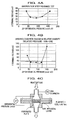
- FIG. 2 is a graph showing a relationship between a moisture content of a gas diffusion layer of an electrode according to the second embodiment of the present invention and an undervoltage (difference between terminal voltages; " ⁇ terminal voltage") of a single cell exhibited before and after an endurance test.
- the endurance test was carried out in a manner as follows:
- ⁇ terminal voltage The difference between terminal voltages exhibited before and after the aforementioned endurance test is employed as ⁇ terminal voltage as shown in FIG. 2. It is understood that the increase in ⁇ terminal voltage indicates the deterioration in performance of the membrane electrode assembly. Hereupon, a practical range of the ⁇ terminal is determined as 30mV or lower.
- the moisture contents of the gas diffusion layer were measured in a manner as follows:
- the electrode or membrane electrode assembly according to the second embodiment of the present invention which basically has the same structure as described in the first embodiment with reference to FIG. 1 includes a gas diffusion layer having a preferable moisture content ranging between 50% and 90% inclusive.
- the difference in structure of the electrode according to the third embodiment from the electrode according to the first and second embodiments is in a water-repellent layer (not shown) for facilitating drainage of water from the gas diffusion layer, which water-repellent layer is provided between the water-holding layer and the gas diffusion layer.
- the water-repellent layer is formed by mixing Teflon® dispersed solution with carbon black powders.
- the electrode according to the third embodiment includes an electrode catalyst layer, a water-holding layer, a water-repellent layer, and a gas diffusion layer; among these components, the gas-diffusion layer is targeted for moisture-content adjustment so that a stable power generation performance can be achieved.
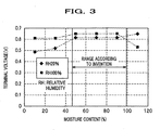
- a relationship between a moisture content of the gas diffusion layer of the electrode and a terminal voltage of a single cell is graphically shown in FIG. 3.
- the abscissa denotes a moisture content (mass %), i.e. , percentage relative to the dry mass of the gas diffusion layer; and the ordinate denotes a terminal voltage of the single cell.
- the moisture contents of the gas diffusion layer were measured in the same manner and calculated by Equation (3) as in the second embodiment.
- the power generation performance of the cell comes as follows:
- the fourth embodiment of the electrode is configured to adjust a differential pressure of reactant gases calculated from two pressures measured at places upstream and downstream of the gas diffusion layer to a specific range, i.e., between 60mmH 2 O and 120mmH 2 O inclusive, so that an adequate level of power generation performance can be stably achieved.
- FIG. 4A is a graph showing a relationship between a differential pressure of reactant gases calculated from two pressures at places upstream and downstream of the gas diffusion layer and an undervoltage (difference between terminal voltages; " ⁇ terminal voltage”) of a single cell exhibited before and after an endurance test.
- FIG. 4B is a graph showing a relationship between a differential pressure of reactant gases calculated from two pressures at places upstream and downstream of the gas diffusion layer and an undervoltage (difference between terminal voltages; " ⁇ terminal voltage”) of a single cell exhibited with relative humidity of the reactant gases at 100% and 20%.
- FIG. 4C is a diagram for explaining a method of measuring the differential pressure. As shown in FIG.
- the differential pressure ⁇ P of the gas diffusion layer can be determined by comparing two pressures measured at places upstream and downstream of the gas diffusion layer when a predetermined flow rate (e.g., 500L/cm 2 /min.) of the reactant gases pass through the gas diffusion layer.
- a predetermined flow rate e.g. 500L/cm 2 /min.
- the differential pressure ⁇ P in a range of the differential pressure ⁇ P below 60mmH 2 O, the lower the differential pressure ⁇ P, the higher the ⁇ terminal voltage becomes. In this range, the gas diffusion layer has water-draining capability enhanced too much to supply hydrogen ion only through the electrolysis of water, and thus corrosion of carbon proceeds.
- the differential pressure ⁇ P beyond 120mmH 2 O the higher the differential pressure ⁇ P, the lower the gas supplying capability becomes due to flooding, thus expanding a region in which fuel gases are insufficient.
- the ⁇ terminal voltage in a range of the differential pressure ⁇ P between 60mmH 2 O and 120mmH 2 O inclusive, the ⁇ terminal voltage is stably maintained at a low level.
- the magnitude of the ⁇ terminal voltage indicates the degree of undervoltage of the terminal voltage, i. e., decrease in output of the solid polymer fuel cell.
- the abscissa denotes a differential pressure of reactant gases calculated from two pressures at places upstream and downstream of the gas diffusion layer, and the ordinate denotes a difference between terminal voltages (" ⁇ terminal voltage") of a single cell exhibited with relative humidity of the reactant gases at 100% and 20%.
- the power generation performance of the cell comes as follows:
- the electrode or membrane electrode assembly according to the fourth embodiment of the present invention which basically has the same structure as described in the first embodiment with reference to FIG. 1 includes a gas diffusion layer exhibiting a preferable differential pressure of the reactant gases calculated from two pressures measured at places upstream and downstream of the gas diffusion layer when a predetermined flow rate of the reactant gases pass through the gas diffusion layer ranging between 60mmH 2 O and 120mmH 2 O inclusive.
- FIG. 5 is a graph showing a relationship between an adhesion rate of a solid polymer membrane and electrode catalyst layer and an undervoltage (difference between terminal voltages; " ⁇ terminal voltage") exhibited before and after the endurance test as in the second embodiment.
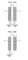
- FIGs. 6A and 6B are schematic diagrams for explaining a method of measuring a charge amount of an electrochemical surface existing in the electrode catalyst layer by a cyclic voltammetry.
- the membrane electrode assembly provided as the fifth embodiment of the present invention basically has the same structure as described in the first embodiment with reference to FIG. 1, and has a preferable adhesion rate of the solid polymer membrane 1 and electrode catalyst layers 2a, 2b, i.e., a percentage of a charge amount of catalytic substances existing on an interface between the solid polymer membrane 1 and the electrode catalyst layer 2a (2b) to a charge amount of all catalytic substances existing in the electrode catalyst layer 1 is configured to be 15% or greater.
- the above charge amounts used to determine the adhesion rate are measured by the cyclic voltammetry, which will be described in detail below with reference to FIGS. 6A and 6B.
- a charge amount of all the catalytic substances existing in the electrode catalyst layers of the electrodes is measured. More specifically, humidifying gases are supplied to the anode A and the cathode C until water is distributed throughout the whole cell; then, a charge amount of electrochemical surfaces of all catalyst particles is measured.
- AdhesionRate SC TC ⁇ 100[%] where SC denotes a charge amount of catalytic substances existing on an interface between the solid polymer membrane and the electrode catalyst layer; and TC denotes a charge amount of all catalytic substances existing in the electrode catalyst layer.
- the more the amount of catalysts existing on the interface between the solid polymer membrane and the electrode catalyst layer i.e., the higher the adhesion rate), the more efficiently the catalysts can be utilized.
- Crystalline carbon fiber (VGCF; manufactured by Showa Denko Kabushiki Kaisha) is mixed with ion conductive polymer (Nafion® , SE20192; manufactured by E. I. du Pont de Nemours and Company) 35g and platinum supporting carbon powders (TEC10E50E; manufactured by Tanaka Kikinzoku Kogyo Kabushiki Kaisha) 2.5g with mass ratio of carbon black to platinum being 50:50 to form a catalyst paste for the cathode.
- the catalyst paste is applied to a FEP (fluoroethylene propylene tetrafluoroethylene-hexafluoro propylene copolymer) sheet so that the amount of platinum on the FEP sheet is 0.3mg/cm 2 .
- the FEP to which the catalyst paste is applied is then dried to form an electrode catalyst layer sheet CA.
- Ion conductive polymer (Nafion® , SE20192; manufactured by E. I. du Pont de Nemours and Company) 36.8g and platinum/ruthenium supporting carbon powders (TEC61E54; manufactured by Tanaka Kikinzoku Kogyo Kabushiki Kaisha) 10g with mass ratio of carbon black to Pt-Ru catalyst being 1:1 are mixed together to form a catalyst paste for the anode.
- the catalyst paste is applied to a FEP (fluoroethylene propylene tetrafluoroethylene-hexafluoropropylene copolymer) sheet so that the amount of platinum on the FEP sheet is 0.15mg/cm 2 .
- the FEP to which the catalyst paste is applied is then dried to form an electrode catalyst layer sheet AN.
- the electrode catalyst layer sheet CA and the electrode catalyst layer sheet AN are transferred to and hot pressed with a solid polymer membrane (electrolyte membrane) to form a membrane electrode assembly (MEA in a broad sense of the term) according to the present invention.
- a water-holding layer is formed using a paste for a water-holding layer prepared by mixing crystalline carbon fiber (VGCF; manufactured by Showa Denko Kabushiki Kaisha) 2.5g with ion conductive polymer (Nafion® , SE20192; manufactured by E. I. du Pont de Nemours and Company) 25g, and carbon black powders (Ketjen Black; manufactured by Cabot Corporation) 5g.
- VGCF crystalline carbon fiber
- Nafion® , SE20192 ion conductive polymer
- E. I. du Pont de Nemours and Company E. I. du Pont de Nemours and Company
- carbon black powders Ketjen Black
- a water-repellent layer is formed using a paste for a water-repellent layer prepared by mixing carbon black powders (Vulcan XC75; manufactured by Cabot Corporation) 18g with Teflon® (polyfluoroethylenepropylene) dispersed solution (L170J; manufactured by Asahi Glass Co., Ltd.) 12g.
- MEA membrane electrode assembly
- a single cell was fabricated by the same process as in Example 1 except that the amount of the paste for water-holding layer applied to water-repellent carbon paper (TGP60; manufactured by Toray Industries, Inc.) was 0.4mg/cm 2 , which was larger than that applied in Example 1.
- TGP60 water-repellent carbon paper
- a single cell was fabricated by the same process as in Example 1 except that the amount of the paste for water-holding layer applied to water-repellent carbon paper (TGP60; manufactured by Toray Industries, Inc.) was 0.2mg/cm 2 , which was smaller than that applied in Example 1.
- TGP60 water-repellent carbon paper
- a single cell was fabricated by the same process as in Example 1 except that the amount of the crystalline carbon fiber added to the water-holding layer was 3.5g, which was larger than that applied in Example 1.
- a single cell was fabricated by the same process as in Example 1 except that the amount of the crystalline carbon fiber added to the water-holding layer was 0g, i.e., no crystalline carbon fiber was added.
- a single cell was fabricated by the same process as in Example 1 except that the water-holding layer as in Example 1 was not applied, but only the paste for water-repellent layer was applied.
- a single cell was fabricated by the same process as in Example 1 except that neither the paste for water-holding layer nor the paste for water-repellent layer as in Example 1 was applied, but only carbon paper (TGPO60; manufactured by Toray Industries, Inc.) rendered water repellent in advance as in Example 1 was used as the gas diffusion layer for forming a membrane electrode assembly.
- TGPO60 carbon paper
- a single cell was fabricated by the same process as in Example 1 except that pressure for hot pressing the electrode sheet to the solid polymer membrane was 10kg/cm 2 .
- a single cell was fabricated by the same process as in Example 1 except that pressure for hot pressing the electrode sheet to the solid polymer membrane was 30kg/cm 2 .
- Results of measurement of power generation performance with relative humidity varied in reactant gases supplied to single cells of Examples 1-3 and Comparative examples 1-4 are shown in FIGs. 7A and 7B.
- the conditions of operation were as follows: (1) fuel gases and oxidant gases were humidified at the same relative humidity.; (2) operating temperature was maintained at 75°C.; (3) pressure of gases supplied to the electrodes (fuel-gas terminal and oxidant-gas terminal) were both 200kPa; and (4) terminal voltages were measured with current density of the electrodes of the cell at 1A/cm 2 .
- the results can be evaluated as follows:
- An electrode for a solid polymer fuel cell includes a gas diffusion layer, an electrode catalyst layer disposed between a solid polymer membrane of the fuel cell and the gas diffusion layer, and a water-holding layer disposed between the gas diffusion layer and the electrode catalyst layer.
- a gas diffusion layer Under high-relative humidity conditions of reaction gases, flooding can be prevented because the electrode catalyst layer is made porous, while under low-relative humidity conditions of reaction gases, sufficient water contents can be stably provided thanks to the water-holding layer so that proton conductivity of the solid polymer membrane can be maintained appropriately. Consequently, high-performance and high-durability electrode and membrane electrode assembly for a solid polymer fuel cell can be provided such that the performance and the durability thereof are not affected by change in relative humidity in reactant gases supplied to the solid polymer fuel cell.
Landscapes
- Chemical & Material Sciences (AREA)
- Chemical Kinetics & Catalysis (AREA)
- General Chemical & Material Sciences (AREA)
- Electrochemistry (AREA)
- Engineering & Computer Science (AREA)
- Manufacturing & Machinery (AREA)
- Sustainable Development (AREA)
- Sustainable Energy (AREA)
- Life Sciences & Earth Sciences (AREA)
- Materials Engineering (AREA)
- Composite Materials (AREA)
- Fuel Cell (AREA)
- Inert Electrodes (AREA)
Applications Claiming Priority (4)
| Application Number | Priority Date | Filing Date | Title |
|---|---|---|---|
| JP2002325401 | 2002-11-08 | ||
| JP2002325400A JP3812901B2 (ja) | 2002-11-08 | 2002-11-08 | 固体高分子型燃料電池用の電極構造体 |
| JP2002325400 | 2002-11-08 | ||
| JP2002325401A JP3778506B2 (ja) | 2002-11-08 | 2002-11-08 | 固体高分子型燃料電池用の電極 |
Publications (3)
| Publication Number | Publication Date |
|---|---|
| EP1437784A2 true EP1437784A2 (de) | 2004-07-14 |
| EP1437784A3 EP1437784A3 (de) | 2007-02-28 |
| EP1437784B1 EP1437784B1 (de) | 2012-05-30 |
Family
ID=32510582
Family Applications (1)
| Application Number | Title | Priority Date | Filing Date |
|---|---|---|---|
| EP03025673A Expired - Fee Related EP1437784B1 (de) | 2002-11-08 | 2003-11-07 | Elektrode für eine Festelektrolyt- Brennstoffzelle |
Country Status (2)
| Country | Link |
|---|---|
| US (1) | US7232627B2 (de) |
| EP (1) | EP1437784B1 (de) |
Cited By (3)
| Publication number | Priority date | Publication date | Assignee | Title |
|---|---|---|---|---|
| EP1701399A1 (de) * | 2005-03-10 | 2006-09-13 | Japan Gore-Tex, Inc. | Film zur Einstellung der Feuchtigkeit bie Brennstoffzellen |
| EP1780822A3 (de) * | 2005-11-01 | 2007-07-04 | Tomoegawa Co., Ltd. | Gasdiffusionselektrode, Membranelektrodeanordnung, Polymerelektrolytbrennstoffzelle und Herstellungsverfahren |
| CN102460790A (zh) * | 2009-06-26 | 2012-05-16 | 日产自动车株式会社 | 气体扩散电极及其生产方法、膜电极组件及其生产方法 |
Families Citing this family (72)
| Publication number | Priority date | Publication date | Assignee | Title |
|---|---|---|---|---|
| JP4482352B2 (ja) * | 2004-03-11 | 2010-06-16 | 本田技研工業株式会社 | 固体高分子型燃料電池 |
| JP2005332693A (ja) * | 2004-05-20 | 2005-12-02 | Aisin Seiki Co Ltd | 燃料電池 |
| WO2005124908A2 (en) * | 2004-06-14 | 2005-12-29 | Ballard Power Systems Inc. | Fluid diffusion layers with in-plane permeability characteristics for improved performance in fuel cells |
| KR100578969B1 (ko) * | 2004-06-30 | 2006-05-12 | 삼성에스디아이 주식회사 | 연료 전지용 전극 및 이를 포함하는 연료 전지 |
| KR100578970B1 (ko) * | 2004-08-25 | 2006-05-12 | 삼성에스디아이 주식회사 | 연료 전지용 전극 및 이를 포함하는 연료 전지 |
| JP4429142B2 (ja) * | 2004-11-10 | 2010-03-10 | 本田技研工業株式会社 | 固体高分子型燃料電池の電極構造体 |
| US8836513B2 (en) | 2006-04-28 | 2014-09-16 | Proteus Digital Health, Inc. | Communication system incorporated in an ingestible product |
| US8802183B2 (en) | 2005-04-28 | 2014-08-12 | Proteus Digital Health, Inc. | Communication system with enhanced partial power source and method of manufacturing same |
| PT1889198E (pt) | 2005-04-28 | 2015-03-06 | Proteus Digital Health Inc | Sistema fármaco-informático |
| US8730031B2 (en) | 2005-04-28 | 2014-05-20 | Proteus Digital Health, Inc. | Communication system using an implantable device |
| US9198608B2 (en) | 2005-04-28 | 2015-12-01 | Proteus Digital Health, Inc. | Communication system incorporated in a container |
| US8912908B2 (en) | 2005-04-28 | 2014-12-16 | Proteus Digital Health, Inc. | Communication system with remote activation |
| WO2007028035A2 (en) | 2005-09-01 | 2007-03-08 | Proteus Biomedical, Inc. | Implantable zero-wire communications system |
| KR100723385B1 (ko) * | 2005-09-23 | 2007-05-30 | 삼성에스디아이 주식회사 | 연료전지용 막전극 접합체 및 이를 채용한 연료전지 시스템 |
| US8232011B2 (en) * | 2005-10-31 | 2012-07-31 | GM Global Technology Operations LLC | Method of operating a fuel cell stack |
| JP5040138B2 (ja) * | 2006-03-29 | 2012-10-03 | トヨタ自動車株式会社 | 燃料電池システムおよび燃料電池セルの運転方法 |
| WO2007130491A2 (en) | 2006-05-02 | 2007-11-15 | Proteus Biomedical, Inc. | Patient customized therapeutic regimens |
| WO2008066617A2 (en) * | 2006-10-17 | 2008-06-05 | Proteus Biomedical, Inc. | Low voltage oscillator for medical devices |
| SG175681A1 (en) | 2006-10-25 | 2011-11-28 | Proteus Biomedical Inc | Controlled activation ingestible identifier |
| US8718193B2 (en) | 2006-11-20 | 2014-05-06 | Proteus Digital Health, Inc. | Active signal processing personal health signal receivers |
| MY165368A (en) | 2007-02-01 | 2018-03-21 | Proteus Digital Health Inc | Ingestible event marker systems |
| CA2676280C (en) | 2007-02-14 | 2018-05-22 | Proteus Biomedical, Inc. | In-body power source having high surface area electrode |
| US9270025B2 (en) | 2007-03-09 | 2016-02-23 | Proteus Digital Health, Inc. | In-body device having deployable antenna |
| US8932221B2 (en) | 2007-03-09 | 2015-01-13 | Proteus Digital Health, Inc. | In-body device having a multi-directional transmitter |
| JP5069927B2 (ja) * | 2007-03-26 | 2012-11-07 | アイシン精機株式会社 | 燃料電池用膜電極接合体およびその製造方法 |
| US8540632B2 (en) | 2007-05-24 | 2013-09-24 | Proteus Digital Health, Inc. | Low profile antenna for in body device |
| DK2192946T3 (da) | 2007-09-25 | 2022-11-21 | Otsuka Pharma Co Ltd | Kropsintern anordning med virtuel dipol signalforstærkning |
| DK2215726T3 (en) | 2007-11-27 | 2018-04-09 | Proteus Digital Health Inc | Transbody communication modules with communication channels |
| CN101946350A (zh) * | 2008-02-22 | 2011-01-12 | 旭硝子株式会社 | 固体高分子型燃料电池用膜电极接合体的制造方法 |
| CN104376659B (zh) * | 2008-03-05 | 2019-10-25 | 普罗透斯数字保健公司 | 多模式通信可摄取事件标记和系统,及使用其的方法 |
| ES2696984T3 (es) | 2008-07-08 | 2019-01-21 | Proteus Digital Health Inc | Infraestructura de datos de marcadores de eventos de ingestión |
| CA2734251A1 (en) | 2008-08-13 | 2010-02-18 | Proteus Biomedical, Inc. | Ingestible circuitry |
| KR101192690B1 (ko) * | 2008-11-13 | 2012-10-19 | 프로테우스 디지털 헬스, 인코포레이티드 | 섭취 가능한 치료 활성화 시스템, 치료 장치 및 방법 |
| KR101126153B1 (ko) | 2008-12-11 | 2012-03-22 | 프로테우스 바이오메디컬, 인코포레이티드 | 휴대용 일렉트로비세로그래피 시스템을 사용한 위장 기능의 평가 및 그 사용 방법 |
| US9659423B2 (en) | 2008-12-15 | 2017-05-23 | Proteus Digital Health, Inc. | Personal authentication apparatus system and method |
| US9439566B2 (en) | 2008-12-15 | 2016-09-13 | Proteus Digital Health, Inc. | Re-wearable wireless device |
| TWI503101B (zh) | 2008-12-15 | 2015-10-11 | Proteus Digital Health Inc | 與身體有關的接收器及其方法 |
| KR20110104079A (ko) | 2009-01-06 | 2011-09-21 | 프로테우스 바이오메디컬, 인코포레이티드 | 약제학적 투여량 전달 시스템 |
| EP2385781A4 (de) | 2009-01-06 | 2014-11-05 | Proteus Digital Health Inc | Nahrungsaufnahme-biofeedback sowie personalisiertes medizinisches therapieverfahren und -system |
| GB2480965B (en) | 2009-03-25 | 2014-10-08 | Proteus Digital Health Inc | Probablistic pharmacokinetic and pharmacodynamic modeling |
| EP2424427B1 (de) | 2009-04-28 | 2021-06-16 | Otsuka Pharmaceutical Co., Ltd. | Hochverlässliche verzehrbare ereignismarker |
| WO2010132331A2 (en) | 2009-05-12 | 2010-11-18 | Proteus Biomedical, Inc. | Ingestible event markers comprising an ingestible component |
| CA2706703C (en) * | 2009-06-10 | 2019-01-08 | Friedrich W. Wieland | Improved electrocatalyst, fuel cell cathode and fuel cell |
| WO2011022732A2 (en) | 2009-08-21 | 2011-02-24 | Proteus Biomedical, Inc. | Apparatus and method for measuring biochemical parameters |
| TWI517050B (zh) | 2009-11-04 | 2016-01-11 | 普羅托斯數位健康公司 | 供應鏈管理之系統 |
| UA109424C2 (uk) | 2009-12-02 | 2015-08-25 | Фармацевтичний продукт, фармацевтична таблетка з електронним маркером і спосіб виготовлення фармацевтичної таблетки | |
| MX2012008922A (es) | 2010-02-01 | 2012-10-05 | Proteus Digital Health Inc | Sistema de recoleccion de datos. |
| JP6463599B2 (ja) | 2010-04-07 | 2019-02-06 | プロテウス デジタル ヘルス, インコーポレイテッド | 小型の摂取可能なデバイス |
| TWI557672B (zh) | 2010-05-19 | 2016-11-11 | 波提亞斯數位康健公司 | 用於從製造商跟蹤藥物直到患者之電腦系統及電腦實施之方法、用於確認將藥物給予患者的設備及方法、患者介面裝置 |
| JP2014504902A (ja) | 2010-11-22 | 2014-02-27 | プロテウス デジタル ヘルス, インコーポレイテッド | 医薬品を有する摂取可能なデバイス |
| US9439599B2 (en) | 2011-03-11 | 2016-09-13 | Proteus Digital Health, Inc. | Wearable personal body associated device with various physical configurations |
| JP5924530B2 (ja) | 2011-06-17 | 2016-05-25 | 日産自動車株式会社 | 燃料電池用ガス拡散層 |
| WO2015112603A1 (en) | 2014-01-21 | 2015-07-30 | Proteus Digital Health, Inc. | Masticable ingestible product and communication system therefor |
| US9756874B2 (en) | 2011-07-11 | 2017-09-12 | Proteus Digital Health, Inc. | Masticable ingestible product and communication system therefor |
| RU2014106126A (ru) | 2011-07-21 | 2015-08-27 | Протеус Диджитал Хелс, Инк. | Устройство, система и способ мобильной связи |
| US9235683B2 (en) | 2011-11-09 | 2016-01-12 | Proteus Digital Health, Inc. | Apparatus, system, and method for managing adherence to a regimen |
| CA2897198A1 (en) | 2012-07-23 | 2014-01-30 | Proteus Digital Health, Inc. | Techniques for manufacturing ingestible event markers comprising an ingestible component |
| BR112015008434A2 (pt) | 2012-10-18 | 2017-07-04 | Proteus Digital Health Inc | aparelho, sistema e método para otimizar adaptativamente a dissipação de potência e a potência de radiodifusão em uma fonte de alimentação para um dispositivo de comunicação |
| JP2016508529A (ja) | 2013-01-29 | 2016-03-22 | プロテウス デジタル ヘルス, インコーポレイテッド | 高度に膨張可能なポリマーフィルムおよびこれを含む組成物 |
| WO2014151929A1 (en) | 2013-03-15 | 2014-09-25 | Proteus Digital Health, Inc. | Personal authentication apparatus system and method |
| WO2014197402A1 (en) | 2013-06-04 | 2014-12-11 | Proteus Digital Health, Inc. | System, apparatus and methods for data collection and assessing outcomes |
| US10175376B2 (en) | 2013-03-15 | 2019-01-08 | Proteus Digital Health, Inc. | Metal detector apparatus, system, and method |
| US9796576B2 (en) | 2013-08-30 | 2017-10-24 | Proteus Digital Health, Inc. | Container with electronically controlled interlock |
| MX356850B (es) | 2013-09-20 | 2018-06-15 | Proteus Digital Health Inc | Métodos, dispositivos y sistemas para recibir y decodificar una señal en presencia de ruido usando segmentos y deformaciones. |
| WO2015044722A1 (en) | 2013-09-24 | 2015-04-02 | Proteus Digital Health, Inc. | Method and apparatus for use with received electromagnetic signal at a frequency not known exactly in advance |
| US10084880B2 (en) | 2013-11-04 | 2018-09-25 | Proteus Digital Health, Inc. | Social media networking based on physiologic information |
| WO2016018200A1 (en) * | 2014-07-27 | 2016-02-04 | Sonova Ag | Batteries and battery manufacturing methods |
| US11051543B2 (en) | 2015-07-21 | 2021-07-06 | Otsuka Pharmaceutical Co. Ltd. | Alginate on adhesive bilayer laminate film |
| JP6552148B1 (ja) | 2016-07-22 | 2019-07-31 | プロテウス デジタル ヘルス, インコーポレイテッド | 摂取可能なイベント・マーカの電磁気的感知および検出 |
| US10820831B2 (en) | 2016-10-26 | 2020-11-03 | Proteus Digital Health, Inc. | Methods for manufacturing capsules with ingestible event markers |
| WO2018155220A1 (ja) | 2017-02-23 | 2018-08-30 | パナソニックIpマネジメント株式会社 | 膜電極接合体および燃料電池 |
| JP6465237B1 (ja) | 2017-10-30 | 2019-02-06 | 凸版印刷株式会社 | 電極触媒層、膜電極接合体及び固体高分子形燃料電池 |
Citations (7)
| Publication number | Priority date | Publication date | Assignee | Title |
|---|---|---|---|---|
| DE19709199A1 (de) * | 1997-03-06 | 1998-09-17 | Magnet Motor Gmbh | Gasdiffusionselektrode mit verringertem Diffusionsvermögen für Wasser und Verfahren zum Betreiben einer Polymerelektrolytmembran-Brennstoffzelle ohne Zuführung von Membranbefeuchtungswasser |
| US5916505A (en) * | 1993-07-13 | 1999-06-29 | Lynntech, Inc. | Process of making a membrane with internal passages |
| EP1150369A1 (de) * | 2000-04-28 | 2001-10-31 | dmc2 Degussa Metals Catalysts Cerdec AG | Gasverteilerstrukturen und Gasdiffusionselektroden für Polymerelektrolyt-Brennstoffzellen |
| WO2002035620A2 (de) * | 2000-10-21 | 2002-05-02 | Ballard Power Systems Inc. | Gasdiffusionselektrode mit erhöhter toleranz gegenüber feuchteschwankung |
| US20020068214A1 (en) * | 2000-12-06 | 2002-06-06 | Reiser Carl Anthony | Fuel cell with an electrolyte dry-out barrier |
| WO2003026035A2 (de) * | 2001-09-18 | 2003-03-27 | Ballard Power Systems Inc. | Membran-elektroden-einheit für eine selbstbefeuchtende brennstoffzelle |
| EP1560283A1 (de) * | 2002-10-28 | 2005-08-03 | HONDA MOTOR CO., Ltd. | Elektrodenstruktur f r eine brennstoffzelledes festpolymertyps |
Family Cites Families (7)
| Publication number | Priority date | Publication date | Assignee | Title |
|---|---|---|---|---|
| JP3555209B2 (ja) | 1994-12-21 | 2004-08-18 | トヨタ自動車株式会社 | 燃料電池の発電層およびその製造方法 |
| JPH09199138A (ja) | 1996-01-19 | 1997-07-31 | Toyota Motor Corp | 燃料電池用の電極または電極・電解質膜接合体の製造方法および燃料電池用の電極 |
| DE60139198D1 (de) | 2000-05-31 | 2009-08-20 | Showa Denko Kk | Elektrisch leitendes, feines kohlenstoffkomposit, katalysator für feste polymerbrennstoffzellen und brennstoffbatterie |
| WO2002005371A1 (fr) * | 2000-07-06 | 2002-01-17 | Matsushita Electric Industrial Co., Ltd. | Procede pour produire un ensemble film-electrodes, et procede pour produire une pile a combustible du type polymere solide |
| EP1357618A1 (de) * | 2001-03-08 | 2003-10-29 | Matsushita Electric Industrial Co., Ltd. | Polymer-elektrolyttyp-brennstoffzelle |
| JP2002289230A (ja) | 2001-03-23 | 2002-10-04 | Matsushita Electric Ind Co Ltd | 高分子電解質型燃料電池 |
| JP3850721B2 (ja) | 2001-12-03 | 2006-11-29 | 本田技研工業株式会社 | 固体高分子型燃料電池の制御方法 |
-
2003
- 2003-11-07 US US10/703,072 patent/US7232627B2/en active Active
- 2003-11-07 EP EP03025673A patent/EP1437784B1/de not_active Expired - Fee Related
Patent Citations (7)
| Publication number | Priority date | Publication date | Assignee | Title |
|---|---|---|---|---|
| US5916505A (en) * | 1993-07-13 | 1999-06-29 | Lynntech, Inc. | Process of making a membrane with internal passages |
| DE19709199A1 (de) * | 1997-03-06 | 1998-09-17 | Magnet Motor Gmbh | Gasdiffusionselektrode mit verringertem Diffusionsvermögen für Wasser und Verfahren zum Betreiben einer Polymerelektrolytmembran-Brennstoffzelle ohne Zuführung von Membranbefeuchtungswasser |
| EP1150369A1 (de) * | 2000-04-28 | 2001-10-31 | dmc2 Degussa Metals Catalysts Cerdec AG | Gasverteilerstrukturen und Gasdiffusionselektroden für Polymerelektrolyt-Brennstoffzellen |
| WO2002035620A2 (de) * | 2000-10-21 | 2002-05-02 | Ballard Power Systems Inc. | Gasdiffusionselektrode mit erhöhter toleranz gegenüber feuchteschwankung |
| US20020068214A1 (en) * | 2000-12-06 | 2002-06-06 | Reiser Carl Anthony | Fuel cell with an electrolyte dry-out barrier |
| WO2003026035A2 (de) * | 2001-09-18 | 2003-03-27 | Ballard Power Systems Inc. | Membran-elektroden-einheit für eine selbstbefeuchtende brennstoffzelle |
| EP1560283A1 (de) * | 2002-10-28 | 2005-08-03 | HONDA MOTOR CO., Ltd. | Elektrodenstruktur f r eine brennstoffzelledes festpolymertyps |
Cited By (3)
| Publication number | Priority date | Publication date | Assignee | Title |
|---|---|---|---|---|
| EP1701399A1 (de) * | 2005-03-10 | 2006-09-13 | Japan Gore-Tex, Inc. | Film zur Einstellung der Feuchtigkeit bie Brennstoffzellen |
| EP1780822A3 (de) * | 2005-11-01 | 2007-07-04 | Tomoegawa Co., Ltd. | Gasdiffusionselektrode, Membranelektrodeanordnung, Polymerelektrolytbrennstoffzelle und Herstellungsverfahren |
| CN102460790A (zh) * | 2009-06-26 | 2012-05-16 | 日产自动车株式会社 | 气体扩散电极及其生产方法、膜电极组件及其生产方法 |
Also Published As
| Publication number | Publication date |
|---|---|
| EP1437784B1 (de) | 2012-05-30 |
| US7232627B2 (en) | 2007-06-19 |
| EP1437784A3 (de) | 2007-02-28 |
| US20040115517A1 (en) | 2004-06-17 |
Similar Documents
| Publication | Publication Date | Title |
|---|---|---|
| EP1437784B1 (de) | Elektrode für eine Festelektrolyt- Brennstoffzelle | |
| Yoda et al. | Effects of operating potential and temperature on degradation of electrocatalyst layer for PEFCs | |
| US7060384B2 (en) | Polymer electrolyte fuel cell | |
| Passos et al. | Studies of the performance of PEM fuel cell cathodes with the catalyst layer directly applied on Nafion membranes | |
| JP3778506B2 (ja) | 固体高分子型燃料電池用の電極 | |
| JP2006054165A (ja) | 固体高分子型燃料電池及び固体高分子型燃料電池の製造方法 | |
| US20070003822A1 (en) | Voltage cycling durable catalysts | |
| US20040166397A1 (en) | Cathode structure for direct methanol fuel cell | |
| US20040247991A1 (en) | Electrode for fuel cell, manufacturing method thereof, and fuel cell | |
| CA2669274C (en) | Membrane-electrode assembly and fuel cell having the same | |
| JP2006318707A (ja) | 固体高分子型燃料電池の電極構造体 | |
| JP2003178780A (ja) | 高分子電解質型燃料電池システム、および高分子電解質型燃料電池の運転方法 | |
| US8420274B2 (en) | Membrane electrode assembly for fuel cell, method of manufacturing the same, and fuel cell including the membrane electrode assembly | |
| JP3812901B2 (ja) | 固体高分子型燃料電池用の電極構造体 | |
| EP1383184B1 (de) | Elektrode für brennstoffzelle und herstellungsverfahren dafür | |
| JP4693442B2 (ja) | ガス拡散電極、その製造方法及び電極−電解質膜積層体 | |
| Sahu et al. | Endurance of Nafion-composite membranes in PEFCs operating at elevated temperature under low relative-humidity | |
| Nishikawa et al. | Preparation of the electrode for high temperature PEFCs using novel polymer electrolytes based on organic/inorganic nanohybrids | |
| JP4429142B2 (ja) | 固体高分子型燃料電池の電極構造体 | |
| CN100506373C (zh) | 基于混合碳载体的改进的聚合物电解质膜燃料电池电催化剂 | |
| JP4880131B2 (ja) | ガス拡散電極およびこれを用いた燃料電池 | |
| Nishikawa et al. | Gas diffusion electrodes for polymer electrolyte fuel cells using novel organic/inorganic hybrid electrolytes: effect of carbon black addition in the catalyst layer | |
| JP2006085984A (ja) | 燃料電池用mea、および、これを用いた燃料電池 | |
| US20070190398A1 (en) | Electrode for fuel cell, fuel cell, and method of preparing electrode for fuel cell | |
| JP4271127B2 (ja) | 固体高分子型燃料電池の電極構造体 |
Legal Events
| Date | Code | Title | Description |
|---|---|---|---|
| PUAI | Public reference made under article 153(3) epc to a published international application that has entered the european phase |
Free format text: ORIGINAL CODE: 0009012 |
|
| 17P | Request for examination filed |
Effective date: 20031107 |
|
| AK | Designated contracting states |
Kind code of ref document: A2 Designated state(s): AT BE BG CH CY CZ DE DK EE ES FI FR GB GR HU IE IT LI LU MC NL PT RO SE SI SK TR |
|
| AX | Request for extension of the european patent |
Extension state: AL LT LV MK |
|
| PUAL | Search report despatched |
Free format text: ORIGINAL CODE: 0009013 |
|
| AK | Designated contracting states |
Kind code of ref document: A3 Designated state(s): AT BE BG CH CY CZ DE DK EE ES FI FR GB GR HU IE IT LI LU MC NL PT RO SE SI SK TR |
|
| AX | Request for extension of the european patent |
Extension state: AL LT LV MK |
|
| 17Q | First examination report despatched |
Effective date: 20070829 |
|
| AKX | Designation fees paid |
Designated state(s): DE GB |
|
| GRAC | Information related to communication of intention to grant a patent modified |
Free format text: ORIGINAL CODE: EPIDOSCIGR1 |
|
| GRAP | Despatch of communication of intention to grant a patent |
Free format text: ORIGINAL CODE: EPIDOSNIGR1 |
|
| RAP1 | Party data changed (applicant data changed or rights of an application transferred) |
Owner name: HONDA MOTOR CO., LTD. |
|
| GRAS | Grant fee paid |
Free format text: ORIGINAL CODE: EPIDOSNIGR3 |
|
| GRAA | (expected) grant |
Free format text: ORIGINAL CODE: 0009210 |
|
| RIN1 | Information on inventor provided before grant (corrected) |
Inventor name: SHINKAI, HIROSHI Inventor name: KOHYAMA, KATSUHIKO Inventor name: WATANABE, SHINYA Inventor name: TANI, MASAKI Inventor name: KAJI, HAYATO Inventor name: FUKUDA, KAORU Inventor name: MURO, TAKESHI Inventor name: INAI, SHIGERU Inventor name: IWASAWA, CHIKARA |
|
| AK | Designated contracting states |
Kind code of ref document: B1 Designated state(s): DE GB |
|
| REG | Reference to a national code |
Ref country code: GB Ref legal event code: FG4D |
|
| REG | Reference to a national code |
Ref country code: DE Ref legal event code: R096 Ref document number: 60341063 Country of ref document: DE Effective date: 20120802 |
|
| PLBI | Opposition filed |
Free format text: ORIGINAL CODE: 0009260 |
|
| PLAX | Notice of opposition and request to file observation + time limit sent |
Free format text: ORIGINAL CODE: EPIDOSNOBS2 |
|
| 26 | Opposition filed |
Opponent name: DAIMLER AG Effective date: 20130228 |
|
| REG | Reference to a national code |
Ref country code: DE Ref legal event code: R026 Ref document number: 60341063 Country of ref document: DE Effective date: 20130228 |
|
| PLAF | Information modified related to communication of a notice of opposition and request to file observations + time limit |
Free format text: ORIGINAL CODE: EPIDOSCOBS2 |
|
| REG | Reference to a national code |
Ref country code: GB Ref legal event code: 746 Effective date: 20130802 |
|
| PLBB | Reply of patent proprietor to notice(s) of opposition received |
Free format text: ORIGINAL CODE: EPIDOSNOBS3 |
|
| REG | Reference to a national code |
Ref country code: DE Ref legal event code: R084 Ref document number: 60341063 Country of ref document: DE Effective date: 20130802 |
|
| PLCK | Communication despatched that opposition was rejected |
Free format text: ORIGINAL CODE: EPIDOSNREJ1 |
|
| REG | Reference to a national code |
Ref country code: DE Ref legal event code: R100 Ref document number: 60341063 Country of ref document: DE |
|
| PLBN | Opposition rejected |
Free format text: ORIGINAL CODE: 0009273 |
|
| STAA | Information on the status of an ep patent application or granted ep patent |
Free format text: STATUS: OPPOSITION REJECTED |
|
| 27O | Opposition rejected |
Effective date: 20141212 |
|
| REG | Reference to a national code |
Ref country code: DE Ref legal event code: R100 Ref document number: 60341063 Country of ref document: DE Effective date: 20141212 |
|
| PGFP | Annual fee paid to national office [announced via postgrant information from national office to epo] |
Ref country code: GB Payment date: 20181107 Year of fee payment: 16 |
|
| PGFP | Annual fee paid to national office [announced via postgrant information from national office to epo] |
Ref country code: DE Payment date: 20191022 Year of fee payment: 17 |
|
| GBPC | Gb: european patent ceased through non-payment of renewal fee |
Effective date: 20191107 |
|
| PG25 | Lapsed in a contracting state [announced via postgrant information from national office to epo] |
Ref country code: GB Free format text: LAPSE BECAUSE OF NON-PAYMENT OF DUE FEES Effective date: 20191107 |
|
| REG | Reference to a national code |
Ref country code: DE Ref legal event code: R119 Ref document number: 60341063 Country of ref document: DE |
|
| PG25 | Lapsed in a contracting state [announced via postgrant information from national office to epo] |
Ref country code: DE Free format text: LAPSE BECAUSE OF NON-PAYMENT OF DUE FEES Effective date: 20210601 |