EP1435291A1 - Vorrichtung und Verfahren zum Anbringen von flexographischen Druckplattensegmenten - Google Patents
Vorrichtung und Verfahren zum Anbringen von flexographischen Druckplattensegmenten Download PDFInfo
- Publication number
- EP1435291A1 EP1435291A1 EP03029584A EP03029584A EP1435291A1 EP 1435291 A1 EP1435291 A1 EP 1435291A1 EP 03029584 A EP03029584 A EP 03029584A EP 03029584 A EP03029584 A EP 03029584A EP 1435291 A1 EP1435291 A1 EP 1435291A1
- Authority
- EP
- European Patent Office
- Prior art keywords
- segment
- segments
- recited
- printing plate
- carrier
- Prior art date
- Legal status (The legal status is an assumption and is not a legal conclusion. Google has not performed a legal analysis and makes no representation as to the accuracy of the status listed.)
- Withdrawn
Links
- 238000000034 method Methods 0.000 title claims abstract description 54
- 238000007639 printing Methods 0.000 claims abstract description 94
- 238000005520 cutting process Methods 0.000 claims abstract description 40
- 230000007246 mechanism Effects 0.000 claims abstract description 24
- 239000000463 material Substances 0.000 claims description 32
- 229920002799 BoPET Polymers 0.000 claims description 9
- 239000005041 Mylar™ Substances 0.000 claims description 9
- 238000001514 detection method Methods 0.000 claims description 6
- 230000033001 locomotion Effects 0.000 description 17
- 239000000853 adhesive Substances 0.000 description 12
- 230000001070 adhesive effect Effects 0.000 description 12
- 238000003384 imaging method Methods 0.000 description 8
- 239000000969 carrier Substances 0.000 description 6
- 238000000926 separation method Methods 0.000 description 4
- 238000007647 flexography Methods 0.000 description 3
- 239000000976 ink Substances 0.000 description 3
- 238000012545 processing Methods 0.000 description 3
- 238000013519 translation Methods 0.000 description 3
- 238000004026 adhesive bonding Methods 0.000 description 2
- 238000007796 conventional method Methods 0.000 description 2
- 230000003247 decreasing effect Effects 0.000 description 2
- 239000003292 glue Substances 0.000 description 2
- 238000012986 modification Methods 0.000 description 2
- 230000004048 modification Effects 0.000 description 2
- 230000003287 optical effect Effects 0.000 description 2
- 230000008569 process Effects 0.000 description 2
- 239000000758 substrate Substances 0.000 description 2
- 239000002390 adhesive tape Substances 0.000 description 1
- 230000008901 benefit Effects 0.000 description 1
- 230000001419 dependent effect Effects 0.000 description 1
- -1 e.g. Substances 0.000 description 1
- 238000003708 edge detection Methods 0.000 description 1
- 238000009459 flexible packaging Methods 0.000 description 1
- 238000007641 inkjet printing Methods 0.000 description 1
- 235000015250 liver sausages Nutrition 0.000 description 1
- 238000004519 manufacturing process Methods 0.000 description 1
- 239000005022 packaging material Substances 0.000 description 1
- 238000012856 packing Methods 0.000 description 1
- 238000012360 testing method Methods 0.000 description 1
- 239000002966 varnish Substances 0.000 description 1
- 238000005406 washing Methods 0.000 description 1
- 239000002699 waste material Substances 0.000 description 1
Images


Classifications
-
- B—PERFORMING OPERATIONS; TRANSPORTING
- B41—PRINTING; LINING MACHINES; TYPEWRITERS; STAMPS
- B41F—PRINTING MACHINES OR PRESSES
- B41F27/00—Devices for attaching printing elements or formes to supports
- B41F27/005—Attaching and registering printing formes to supports
Definitions
- This invention relates to the field of printing, and in particular to a method and apparatus for mounting flexographic or letterpress plate segments onto a printing plate carrier.
- Flexography and letterpress use printing cylinders on which printing plates are mounted using different mounting methods. When printing in color, one cylinder is used for each color, i.e., for each color separation.
- a known manual method for mounting the plate segments onto a carrier to produce a cylinder with multiple plate segments includes first producing flat printing plate sheets, cutting the plate segments, and manually mounting the segments onto a printing plate carrier such as a drum, sleeve, or a mylar sheet.
- a printing plate carrier such as a drum, sleeve, or a mylar sheet.
- the manual method includes applying glue to the back of the printing plate segments or making the printing plate carrier adhesive, e.g., by applying glue or by using double sided adhesive tape.
- the manual method further includes the operator manually aligning register marks on the printing plate segments with marks that have been provided by a mounting apparatus.
- the operator can use a prior-art mounting apparatus for this.
- the apparatus helps registering by using a half-transparent mirror or a video screen to display a register mark on top of the image of the plate segments.
- an operator manually decides where to mount the plate segment.
- the quality of the resulting printing cylinders may vary depending on the skill of the operator.
- the mounting may take a relatively long time, especially when high precision is required.
- large plate segments are more difficult to mount than smaller plate segments, mainly because it is difficult for human operators to handle large plate segments.
- a manual mounting machine An apparatus that helps a human operator to mount printing plate segments onto a printing cylinder is called a manual mounting machine herein, and the mounting method is called a manual mounting method.
- Blank, unimaged plate segments are applied on a cylindrical plate carrier, typically a sleeve, and imaged in a computer-to-plate drum imaging device such as the Esko-Graphics Cyrel Digital Imager (Esko-Graphics NV, Gent, Belgium, the applicant of the present invention).
- the imaging device is used to directly expose the sleeve carrying the flexographic plate segments. After exposure, the cylindrical plate carrier with the exposed plate segments attached is moved away from the imaging device and processed in round washing equipment. Because the printing plate segments are not removed from the sleeve or printing cylinder for the processing, the image register is maintained throughout the process until printing.
- One of the problems with using a plurality of segments is accurate registration. As a result, imaging on a single sheet is still often used in flexography, even at the cost of the wasted plate material.
- the printing plate carrier is on a cylindrical drum, i.e., is a cylindrical plate carrier, while in another embodiment, the carrier is a sheet laid out on a substantially flat surface that, after mounting, can be placed on a drum.
- the method includes accepting positioning data indicative of a set of first positions and loading the imaged segments onto a working surface of the loading table at approximately the corresponding first positions.
- the method further includes, for each segment, detecting the position of the segment on the table, and using a mechanical pick-up system to pick up the segment and to carry the segment to a final position on the carrier.
- the carrying is via a path determined using the detected position on the table and the final position.
- the table's working surface has a set of vacuum holes coupled to a vacuum system.
- the mechanical pick up system includes a plurality of suction caps coupled to the vacuum system to pick up the plate.
- One version includes a mechanism for cutting the segments from the sheet.
- the mechanical pick-up system includes one or more pick-up arms.
- Each arm is rotatably connected to the loading table and has one or more suction caps coupled to the vacuum system.
- one version has four pick-up arms.
- Each arm has a head that is movable lengthwise along the arm. The head includes a video camera and a single suction cap coupled to the vacuum system.
- each imaged plate segment has a plurality of register points.
- the detecting of the position of the segment detects the register marks.
- the detecting uses the video detecting system, e.g., the cameras mounted on the arms of the mechanical pick-up system in the version that has such arms.
- the picking up includes positioning the pick-up system such that the suction caps are close to the detected positions of the register marks, such that the picking up is at pick-up points close to register marks.
- the carrying of the segment includes initially rotating the cylindrical carrier so that the location on the carrier of the roll-off point of the segment is such that the mechanical pick up system can place the roll-off point of the segment thereon.
- the roll-off point is a point on the final position of the segment.
- the method includes carrying the segment such that the segment's roll-off point can be placed on the location on the carrier of the roll-off point, placing the segment's roll-off point onto the roll-off point location on the carrier, and placing the remainder of the segment on the carrier by translating the mechanical pick-up system and simultaneously rotating the cylinder such that the segment ends placed at its final position.
- the method includes picking up each plate segment at more than two independent points and carrying each segment to a respective final position on the carrier, such that some of the plate segments may need to be deformed to reach their respective final position. For a plate segment that is so deformed, the final position cannot be reached by picking up the plate segment at only two points because of the required deformation of the plate.
- the apparatus includes a computer system to control the various elements and functions such as the motion of the mechanical pick-up system, the detection of position by the video detection system, and the determining of the path for carrying the plate segments.
- Described herein is a method for mounting imaged printing plate segments onto a printing plate carrier, and an apparatus for such mounting.
- the method and apparatus can be used to create cylindrical plate carriers such as printing drums, cylindrical printing sleeves or mylar sheets that may be wrapped around a printing drum.
- the plate carriers contain segments of printing plate material, mounted such that the plate segments are registered with respect to each other on the same carrier, and such that when a set of cylindrical plate carriers is used to print a set of inks onto the same substrate, the plate segments on one carrier are registered relative to the plate segments on the other cylindrical plate carriers.
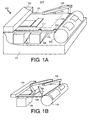
- FIG. 1A shows one embodiment of a mounting device 100.
- the device includes a base 111 and a substantially planar loading table 101 attached to the base 111.
- the base 111 is shown cut-away and details of how the components are coupled to the base are not shown for the sake of clarity.
- Part of the planar loading table is the working surface 107.
- the loading table includes a set of vacuum holes 209 (see FIG. 2) to force printing plate material to be attached to the loading table when a vacuum is applied.
- the vacuum holes are coupled to a vacuum system 106 that can be switched on or off under control of a computer system 105.
- the mounting device further includes a mechanical pick-up system.
- One mechanical pick-up system embodiment includes a set of robotic pick-up arms 109 rotatably coupled to the table 101, either by a direct rotatable connection to the table 101, or, in another embodiment, by a rotatable connection to the base 111 to which the table 101 is connected.
- the apparatus further includes a video detection system that in one embodiment includes a video camera on each pick-up arm 109.
- Each pick up arm 109 has a pick-up mechanism that includes at least one suction cap coupled to the vacuum system 106.
- One pick-up arm 109 is shown in FIG. 1A. In this embodiment, three other pick-up arms are located at locations 117, 119, and 121.
- FIG. 1B shows all four pick-up arms 109.
- the video camera of each pick-up arm is interfaced to the computer system 105 to provide an optical recognition system for a set of locations.
- FIG. 3 shows one embodiment of the robotic pick-up arm 109 in more detail.
- the arm 109 is rotatably coupled to the table, e.g., by being rotatably attached to the base 111.
- a motor 301 and motor control system connected to the computer system 105 provide for the arm to rotate under control of the computer system 105.
- the approximate range of rotation is shown as AA.
- the suction cap pick-up mechanism is shown as 311 and the video camera is shown as 309. Both the suction cap and the camera system are mounted on a head 307 that moves along the arm, also under control of the computer system 105.
- the motion of the head uses a lead screw 305 and a second motor 303 with a control system connected to the computer system 105.
- BB The approximate range of motion along the arm 109 is shown as BB.
- a linear motor provides the motion along of the head along the arm. See US-4,543,615 for a description of a linear motor. US- 4,543,615 is incorporated herein by reference.
- the suction cap of pick-up mechanism 311 is movable towards or away from the loading table under control of the computer system 105.
- the suction caps of the robotic pick-up arms 109 may be positioned to be on top of a desired location on the loading table working surface 107 on which a plate segment was placed, and lowered to make contact or almost make contact with the plate segment.
- the vacuum can then be turned on (under control of the computer system 105) so that the pick-up mechanism's suction cap attaches itself to any plate material on the loading table 101.
- Using the four pick-up arms 109 thus provides a mechanical pick-up system that can pick up by using a plurality of suction caps at a plurality, e.g., up to four locations.
- the vacuum applied to the loading table's vacuum holes 209 is selected to be low enough relative to the vacuum used on the arms' suction caps so that a set of suction caps applied to a plate material segment can remove the plate material segment from the loading table 101.
- One embodiment includes a pneumatic system coupled to each arm's pick-up mechanism 311 to move the pick-up mechanism 311 towards or away from the loading table 101 under control of the computer system 105.
- each pick-up arm 109 is movable towards or away from the loading table 101.
- the computer system 105 can direct the video cameras 309 and the suction caps of the pick-up arms 109 to a set of locations on the working surface 107 of the loading table 101.
- positioning the arm 109 is relative to the loading table surface that provides a frame of reference.
- the device 100 also includes a cutting bridge 103 across the loading table 101 (the y-direction) with a cutting knife mechanism.
- the cutting bridge 103 includes a motor and motor control mechanism that can move the bridge 103 along the loading table 101 on two rails in the x-direction perpendicular to the bridge 103 under control of the computer system 105.
- One such rail 115 is shown in FIG. 1A.
- the bridge 103 further includes a motor and motor control mechanism connected to the cutting knife mechanism to move the cutting knife mechanism along the length of the bridge under control of the computer system 105 so that by a combination of movement of the bridge 103 along the loading table 101 and the cutting knife mechanism along the bridge 103, the computer system 105 can direct the cutting knife mechanism to any location in on the loading table surface.
- a further motor and control system directs the cutting of any plate material placed on the loading table 101.
- One embodiment uses a commercially available cutting loading table system for the cutting bridge 103 and the cutting knife mechanism and all motors and control systems for the bridge 103 and cutting mechanism.
- the commercially available cutting loading table system is the Kongsberg XL cutting loading table range made by Esko-Graphics NV, of Belgium (formerly Barco Graphics NV), the proprietor of the present invention.
- a brochure describing the Kongsberg XL cutting loading table is available in the Web at http://unix.barco.com/graphics/kongsberg/XLloading tables.htm and incorporated herein by reference.
- the control system software of the Kongsberg XL is included in computer system 105.
- Cutting information may be transferred to the cutting loading table control system to control the cutting of a sheet of plate material placed on the loading table 101.
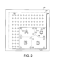
- FIG. 2 shows a top view of the loading table 101 including the working surface 107 within the dashed lines.
- Two of the vacuum holes are shown as having reference numeral 209.
- the loading table 101 includes two alignment edges 203 and 205 in the x- and y-directions, respectively used as registration guides.
- the alignment edges 203, 205 provide for rapidly aligning the sheet so that there is approximate registration relative to the loading table frame.
- Such approximate registration for example, positions a sheet to within 1 mm in one or both of the x and y-directions relative to the positions of the alignment edges 203, 205, and to less than 2 degrees error in rotation.
- FIG. 1 positions a sheet to within 1 mm in one or both of the x and y-directions relative to the positions of the alignment edges 203, 205, and to less than 2 degrees error in rotation.
- the sheet 2 shows a flexographic plate sheet 211 positioned against the alignment edges 203, 205.
- the dashed lines 215 show a cutting path for the cutting knife.
- the sheet 211 shown has four imaged segments. Each segment includes four register marks such as mark 217. On each segment, the dotted lines such as line 213 show the locations where the four suction caps of the pick-up mechanisms 311 on the four arms 109 are positioned to pick up and move the plate segments after cutting (see below).
- the set of printing plate segments on the sheet 211 is maintained on the working surface 107 by the vacuum being turned on to the vacuum holes 209.
- the loading device 100 further includes a clamped cylindrical drum 113 that can rotate around its axis.
- the axis of rotation is parallel to the y-direction.
- the drum 113 is adapted to fit a plate carrier for mounting flexographic plate material thereon.
- the plate carrier is mounted on the drum 113.
- a sleeve is mounted on the drum 113, or a mylar sheet is rolled onto the drum 113, and so forth.
- the drum system includes one or more motors and an associated motor control system coupled to the computer system 105. Rotation of the drum 113, i.e., of the plate carrier, is controlled by software in computer system 105.
- the working surface 107 of the loading table 101 is approximately 90 cm (in the x-direction) by 120 cm wide (in the y-direction).
- a load device may be used, for example, for printing cylinders of up to 120 cm in width.
- Such cylinders may be used, for example, for high quality printing of packaging material such as flexible packaging and folded cartons.
- a second embodiment accommodates printing cylinders of up to 240 cm in width. In such a case, the working surface 107 is approximately 160 cm (in the x-direction) by 240 cm wide (in the y-direction).
- the computer system 105 includes a user interface.
- the computer system also includes the necessary control logic interfaced to the various motor drives and motor control systems, to the cutting knife, to the vacuum system 106, and to the video cameras 309 such that the combination of a video camera 309, interface, and software on computer system 105 forms an optical recognition system.
- the mounting device 100 Operation of the mounting device 100 is described herein for the case of flexographic plate segments being mounted onto an adhesive sleeve such as a McDermid Twinlock sleeve (MacDermid Printing Solutions, LLC, Atlanta, GA).
- the mounting system is easily adapted to other printing plates, not just flexographic plates, and to other types of printing plate carriers.
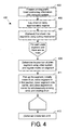
- FIG. 4 shows a flow chart of one embodiment of a method 400 of mounting plate segments using an embodiment of the mounting device 100.
- the method starts at step 403 with producing printing plate sheets 211.
- This can use any conventional method and results in imaged sheets of flexographic plate.
- Each sheet 211 can contain one or multiple parts (segments) of one or multiple separations.
- the printing plate sheets 211 are produced in a manner that reduces waste using the imaging method described in above-mentioned incorporated-by-reference US-2003/053138.
- the imaging method described in this document includes processing full-format screened data in a computer to identify zones that contain printable information. The zones are packed, imaged onto a set of printing plate sheets 211, e.g., one sheet 211 for each separation so that each sheet 211 may be cut into flexographic plate segments.
- the method includes imaging a set of register marks for each segment. US-2003/053138 is incorporated herein by reference.
- the positioning data for the segments is transferred to computer system 105.
- the computer system 105 contains information on where each printing plate segment is to be placed on a printing sleeve (the respective final position) and where each segment is located in the printing plate sheet 211 prior to cutting.
- a step 405 the sheet 211 of printing plate material containing the flexographic plate segments is laid on the loading table 101 against the alignment edges 203 and 205 (see FIG. 2). In this manner, plate can be approximately registered with respect to the mounting system, e.g., with less than 1 mm error in position and less than 2 degrees error in rotation.
- the vacuum system 106 is turned on so that the vacuum applied to the vacuum holes 209 maintains the sheet in position on the working surface 107.
- the cutting knife mounted on cutting bridge 103 cuts the sheet 211 into individual segments along a cutting path (dashed lines 215 in FIG. 2).
- the cutting path 215 is determined by the computer system 105 using information obtained during the imaging and loaded into computer system 105.
- a plurality, denoted N of flexographic plate segments are on the loading table 101 positioned at their initial location, i.e., approximately registered.
- steps 409 and 411 are executed for each plate material segment sequentially until there are no more segments.
- the steps are described for one plate segment, and are identical for the other segments.
- the location of the flexographic plate segment is determined using the video detection system.
- the computer system 105 includes information on the relative locations of the register marks 217 on the segment relative to the sheet 211 of plate material, hence the approximate location of the flexographic plate segment is known.
- the segment includes a set of register marks 217.
- the register marks 217 each have a cross form and are positioned near the outside border of the segment of plate material. The locations of such a mark 217 is detected. The corresponding location of the register mark 217 on the final printing plate carrier is stored in the computer system105.
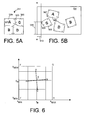
- FIG. 2 shows a simple example of four plate segments that each includes an image and four register marks 217.
- FIG. 5A shows the same segments in their initial position.
- step 409 the pick-up arms 109 move to positions such that each arm's video camera 309 is approximately over a register mark 217.
- each register mark 217 up to the number of pick-up arms 109 ⁇ is in a video camera's field of view.
- the video information is input to the computer system 105 and the register mark 217 is recognized in order to determine the exact position of the register mark 217. Because step 405 positions the segments approximately, e.g., to within one mm in each orthogonal direction, the video registering system can limit its search in a small region around theoretical position.
- FIG. 6 shows the region around a single register mark 217.
- a search is made over an area FGHJ between x MIN and x MAX in the x-direction, and y MIN and y MAX in the y-direction.
- the distances (x NAX -x MIN ) and (y MAX- y MIN ) are related by the accuracy of loading the sheet 211, e.g., the register mark length +2 mm in the x- and y-directions, respectively.
- the mark 217 preferably consists of two crossed lines, with the register point being the intersection of the lines.
- the register marks 217 are located far enough away from any image on the plate such that no image data is present within the register mark search region FGHJ.
- image of the region around the register mark 217 is digitized and analyzed by computer system 105.
- the edge locations are determined in one embodiment by a simple edge enhancement and scanning process for edge detection.
- the enhanced image data is scanned in the x- and y-directions to determine a set of x-values and y-values for the edges in each register mark 217.
- Each x-position is scanned up (increasing y) and down (decreasing y) to yield a pair of y-values for the edge.
- the average of the y-values for scanning up and down is determined as the register mark location.
- one or two edge locations are determined at each x-value.
- one or two edge locations are determined for each y-value.
- two lines AB and CD are determined (see FIG. 6).
- the intersection of the two lines, shown as E, can then be determined for each register mark 217.
- the register mark data is in the form of coordinates x R and y R .
- One embodiment assumes no deformation, e.g., stretching of the plate segment occurs.
- An alternate embodiment assumes deformation can occur.
- the locations of more than two register marks 217 are used to determine the deformation.
- each arm 109 is moved so that each suction cap is approximately at the location of a register mark. This is preferred because the region around each register mark 217 is known to be free of printing information, so is flat. This permits the suction cap to pick up the plate without damaging the plate.
- the dimensions of the block on which the pick-up mechanism 311 and video camera 309 are mounted is such that the minimum distance between the pick-up suction caps of any two arms 109 is about 10 cm.
- the minimum distance between the pick-up suction caps of any two arms 109 is about 10 cm.
- four register marks 217 may be used, and the all four pick-up arms 109 can be used to pick up the segment.
- For smaller segments as few as a single pick-up arm 109 may be used, and typically two or more pick-up arms 109 are used.
- a step 411 the suction caps of the pick-up mechanisms 311 are moved over the register marks 217 and lowered.
- the vacuum is turned on for each pick-up mechanism 311 on each arm 109 so that the segment is locked onto the set of arms 109.
- the vacuum applied to the pick-up arm's suction cap is selected to produce a force higher than that applied at the vacuum holes 209 on the loading table surface.
- the set of pick-up arms 109 together now pick up the segment of printing plate by lifting the suction caps with the vacuum on.
- the plate is typically kept horizontal.
- the set of arms 109 together move under computer control to carry the plate segment to the correct position on the drum 113 on which a printing plate carrier is held.
- the paths for the four arms 109 are determined on the computer system 105 so that each register mark 217 ends up at the correct position on the carrier.
- Each path includes translation of the arms 109 in a manner that (1) rotates the segment to the correct orientation, and (2) moves the so-called "roll-off point" on the segment to the position immediately above the axis of rotation of the drum 113 at the correct y-position of the roll-off point.
- the roll-off point is the point of the segment that would be the last point touching the drum surface if the plate segment was correctly positioned and was to be removed in a first direction, e.g., counterclockwise.
- FIG. 5A shows the exposed plate 211 (FIG. 2) after cutting.
- FIG. 5B shows the carrier 511 unrolled with the plate segments of plate 211 correctly placed.
- FIG. 5B shows exaggerated rotation of the segments to the correct orientation.
- the roll-off point on any segment when the first rotation direction is counterclockwise is the point on the segment with the least x-value on the unrolled carrier 511.
- the counterclockwise roll-off point is the top left-hand corner 503.
- the motion of the arms 109 is such that point 503 is moved to be on top of the axis of the drum 113 at the correct y-position shown as distance 515.
- segment 509 that has an "A.”
- the path of the arms 109 is calculated so that segment 509 is rotated to its correct orientation and so that point 507 (the counterclockwise roll-off point) is moved to be above the axis of rotation at the correct final y-position of point 507.
- the rotation of the drum 113 in the first direction also is determined so that the roll-off point is located above the axis of rotation.
- the paths are calculated so that the segment of plate material is not stretched, i.e., the distance between the suction caps on the pick-up arms 109 is maintained constant throughout the motion.
- the distance between the suction caps is modified during the motion to correct for any stretching or other deformation that may have been determined.
- the drum 113 is rotated in the first direction, e.g., counterclockwise so that the roll-off point is above the axis of rotation, and the arms 109 are moved to rotate the segment to the correct orientation and move the segment so that the roll-off point is above the axis of rotation of the drum 113 at the correct position along the rotation axis.
- the plate is now brought down until the roll-off point touches the drum 113.
- the roll-off point e.g., point 503 in the case of segment 505 now sticks to the carrier 511 on the drum 113.
- the whole carrier 511 is adhesive.
- the drum 113 is now rotated in the direction such that the segment is laid down on the surface of the carrier 511, e.g., clockwise while the arms 109 simultaneously move so that the segment is translated at a speed that is matched to the rotation of the drum 113.
- the rotation of the drum 113 and simultaneous translation of the segment continues until the whole segment adheres to the carrier 511 on the drum 113.
- the vacuum is released as each suction cap passes over the axis of rotation of the drum 113.
- the motion of the arms 109 for each segment including the picking up of each segment from the working surface 107 of the loading table 101, the rotation and translation of the segment to the intermediate position so that the roll-off point is above the rotation axis, the initial rotation of the drum 113, the lowering of the segment onto the drum 113, and the rotation of the drum 113 simultaneous with the motion of the arms 109 and release of the suction caps is controlled by executing real-time control software on computer system 105 based on the determined paths and motions.
- the method repeats steps 409 and 411 for each segment that is to be mounted on the plate carrier.
- the one carrier may include segments from more than one sheet 211 of plate material. In such a case, step 405 and 407 are repeated for any additional sheets 211 needed for the one plate carrier 511.
- the method results in a plate carrier 511, e.g., a sleeve in the drum carrying the segments correctly placed for a separation.
- a plate carrier 511 e.g., a sleeve in the drum carrying the segments correctly placed for a separation.
- the newly created printing plate carrier 511 is used to make an impression on a sheet of substrate, e.g., paper mounted on a second drum, or in an alternate embodiment, on a second loading table at the other side of the printing drum.
- a sheet of substrate e.g., paper mounted on a second drum, or in an alternate embodiment, on a second loading table at the other side of the printing drum.
- One embodiment of optional step 413 includes inking the plate with the corresponding ink. Such inking may be carried out manually with a hand roller.
- an automatic inking system may be used. Automatic inking systems are known in the art. For example, proofing systems for flexographic plates that include automatic inking systems are known in the art, and such an automatic inking system may be adapted to use in the mounting system described herein.
- the plate carrier ⁇ the drum sleeve or mylar sheet the drum ⁇ is removed from the device 100 and is ready for use in printing.
- the next printing plate carrier can now be loaded.
- a new plate sheet can be loaded or the remainder of the previous sheet can be used, as required.
- a mounting device 700 comprising a base 701 is shown in FIG. 7.
- the drum 113 of FIG. 1 is replaced by a flat surface 707 on an extension table 703 onto which the sheet carrier can be loaded.
- the surface 707 includes vacuum holes coupled to the vacuum to hold the sheet onto the surface.
- step 411 includes applying an adhesive after the plate is lifted from the loading table 101 and before the plate segment is lowered onto the plate carrier 511.
- step 411 includes automatically applying the adhesive.
- An embodiment of the mounting system includes a gluing system that uses a gluing roller coupled to the computer system 105 and located between the plate sheet location and the drum 113 so that adhesive is applied under control of the computer system 105 after the plate is lifted from the loading table 101 and before the plate segment is lowered onto the plate carrier 511.
- Another version of the method includes applying adhesive by hand.
- the mounting device is suitable for multi-ink printing of screened images.
- the screen directions need to be accurate relative to each other.
- the plate segments are imaged in the same direction.
- the packing is such that all plate segments are oriented the same way, or rotated ⁇ 90°.
- each segment needs to be rotated either by a relatively small amount, e.g., in the range of-3 to +3 degrees, to account for misplacement on the table, or by an angle close to 90 degrees, e.g., 87 to 93 degrees or -93 to -87 degrees.
- the embodiments shown in FIGS. 1A and 1B are aimed at rotating by a small angle. If rotation by an additional ⁇ 90° is desired, the individual pieces would need to be rotated manually.
- Each of the pickup arms 109 then, in the step 409, determine the position of plate segment using the video system to detect the position of the register marks 217 on the segment.
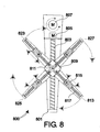
- FIG. 8 shows an alternate pick-up arm system 800 for the mounting device 100, 700.
- the mounting device 100, 700 uses only a single pick-up arm system 800.
- the system 800 includes an arm 801 rotatably mounted to the table, e.g., by being rotatably attached to the base 111.
- a motor 807 and motor control system connected to the computer system 105 provide for the arm 801 to rotate under control of the computer system 105.
- a head 809 moves along the arm 801 using a lead screw 803 and a second motor 805 with a control system connected to the computer system 105.
- An alternate embodiment uses a linear motor for the motion of the head 809.
- An assembly having four limbs 813, 823, 825, and 827 at forming an "X" is rotatably attached to the head 809 and can rotate using a motor 811 coupled to the computer system 105.
- each of the limbs 813, 823, 825, and 827 is identical.
- Limb 813 includes a head 815 on which is mounted a suction cap pick-up mechanism and a video camera.
- the head 815 is movable along the limb 813, also under control of the computer system 105.
- the motion of the head 815 uses a lead screw 817 and yet another motor (not represented in the drawings), with a control system connected to the computer system 105.
- An alternate embodiment has head 809 mounted on a bridge (not represented in the drawings) across the loading table (the y-direction) that includes motor and motor control mechanism that can move the bridge along the loading table in the x-direction perpendicular to the bridge under control of the computer system 105 on two rails.
- the head 809 moves along the bridge under control of the computer system 105.
- Both the single arm and single bridge embodiment that includes the head 809 of four limbs 813, 823, 825, and 827 provides for rotating the plate segment any arbitrary angle once the plate segment is picked up.
- An improved embodiment applicable to the single arm and the bridge configurations has pairs of limbs on the head 809 be co-linear, and allows the pairs of limbs to rotate with respect to each other.
- an additional motor and motor control system coupled to the computer system 105 are included to permit co-linear limbs 813 and 823 to rotate independently of co-linear limbs 825 and 827. That provides 4 arbitrary pick up points.
- One embodiment includes a video camera mounted in each pick-up arm.
- the video camera is positioned over a register mark and an image taken and input to the computer.
- the video camera may be a CCD camera, but this aspect the invention does not depend on the type of camera used.
- Software in the computer system then determines the position of the register mark.
- the video detecting system used to detect the position of each segment's the registration marks includes a laser scanner rather than a video camera on each pick-up arm.
- the laser scanner includes a laser source and laser detector. The region around each register mark is optically scanned to determine the location of the lines of each register mark.
- step 405 lays a plurality of printing plate sheets on the loading table 101 at different positions.
- FIG. 1A shows two plate sheets. As long as each of these sheets is laid down with approximate registration so that the computer system 105 knows the approximate position, e.g., to within 1 mm in the x- or y-directions, the different plate segments are handled one by one sequentially, fully under control of the computer system 105, as described above.
- the term computer system is used herein to indicate any device or system for controlling the devices such as the mechanical pick-up system. Thus, the term includes special purpose controllers, and other special purpose devices.
- the system 105 for example, need not even include a traditional computer.
- cylindrical plate carrier is meant a sleeve or a printing cylinder, etc., or a sheet such as a sheet of mylar that has been wrapped around a cylinder.
- rotatably coupled to the loading table includes, for example when applied to a pick-up arm the case that the table is connected to a base and that the pick-up arm is rotatably connected to the base. No direct connection between the table and the arm need occur, although the term includes such a case.
Landscapes
- Exposure And Positioning Against Photoresist Photosensitive Materials (AREA)
- Inking, Control Or Cleaning Of Printing Machines (AREA)
Applications Claiming Priority (2)
| Application Number | Priority Date | Filing Date | Title |
|---|---|---|---|
| US10/336,944 US6823793B2 (en) | 2003-01-06 | 2003-01-06 | Method and apparatus for mounting flexographic plate segments |
| US336944 | 2003-01-06 |
Publications (1)
| Publication Number | Publication Date |
|---|---|
| EP1435291A1 true EP1435291A1 (de) | 2004-07-07 |
Family
ID=32507423
Family Applications (1)
| Application Number | Title | Priority Date | Filing Date |
|---|---|---|---|
| EP03029584A Withdrawn EP1435291A1 (de) | 2003-01-06 | 2003-12-22 | Vorrichtung und Verfahren zum Anbringen von flexographischen Druckplattensegmenten |
Country Status (2)
| Country | Link |
|---|---|
| US (2) | US6823793B2 (de) |
| EP (1) | EP1435291A1 (de) |
Cited By (13)
| Publication number | Priority date | Publication date | Assignee | Title |
|---|---|---|---|---|
| WO2005090079A1 (en) * | 2004-03-23 | 2005-09-29 | Av Flexologic B.V. | Automatic mounting system |
| WO2006120171A3 (en) * | 2005-05-09 | 2007-04-05 | Goss Graphic Systems Ltd | Printing plate unloading apparatus and method |
| EP1952985A3 (de) * | 2007-02-02 | 2008-12-17 | Andrea Franke | Verfahren und Vorrichtung zur Positionierung von Klischees auf Prägewerkzeugen |
| WO2009099541A3 (en) * | 2008-02-05 | 2009-10-01 | Eastman Kodak Company | Reducing waste in imaging flexographic plates |
| EP2127872A1 (de) * | 2008-05-29 | 2009-12-02 | Andrea Franke | Verfahren und Vorrichtung zur Positionierung von Klischees auf Prägewerkzeugen |
| US8051774B2 (en) | 2004-04-29 | 2011-11-08 | Goss Graphic Systems Limited | Printing plate module, printing press, and method of mounting plates |
| NL2005383C2 (nl) * | 2010-09-22 | 2012-03-26 | Av Flexologic Bv | Inrichting en werkwijze voor het positioneren van een drukplaat op een drager. |
| DE102006060464C5 (de) * | 2006-12-19 | 2013-12-24 | Bobst Bielefeld Gmbh | Verfahren zum Einstellen einer Walze in einer Rotationsdruckmaschine |
| EP1916102B2 (de) † | 2006-10-23 | 2014-06-25 | Bobst Bielefeld GmbH | Verfahren zur Justierung einer Walze in einer Druckmaschine |
| EP2397327A3 (de) * | 2010-06-18 | 2015-08-12 | Esko-Graphics Imaging GmbH | Nichtdruckende Registrierungsmarkierungen auf einer Druckplatte |
| ITUB20155488A1 (it) * | 2015-11-11 | 2017-05-11 | Biessse Equipment Solutions S R L | Apparecchiatura e procedimento per l'applicazione di fotopolimeri ad una manica per stampa flexografica |
| WO2017081642A1 (en) * | 2015-11-11 | 2017-05-18 | Biessse Equipment Solutions S.R.L. | An apparatus and process for preparing a flexographic printing sleeve |
| CN111225798A (zh) * | 2017-08-24 | 2020-06-02 | 埃斯科绘图成像有限责任公司 | 印版节段安装系统和方法 |
Families Citing this family (17)
| Publication number | Priority date | Publication date | Assignee | Title |
|---|---|---|---|---|
| US7171901B2 (en) * | 2001-10-18 | 2007-02-06 | Kodak Graphic Communications Canada Company | Flexographic printing method |
| US7717040B2 (en) * | 2007-06-05 | 2010-05-18 | Eastman Kodak Company | Plate cutting and imaging with same device |
| SE531852C2 (sv) * | 2007-12-17 | 2009-08-25 | Tetra Laval Holdings & Finance | Metod att bereda tryckformar för flexografisk tryckning och ett system samt beredningsbord som används i metoden |
| US8227769B2 (en) * | 2008-05-27 | 2012-07-24 | Esko-Graphics Imaging Gmbh | Curing of photo-curable printing plates with flat tops or round tops |
| US8129091B2 (en) * | 2008-05-28 | 2012-03-06 | E.I. Du Pont De Nemours And Company | Method for preparing a composite printing form using a template |
| JP5119191B2 (ja) * | 2009-03-31 | 2013-01-16 | 富士フイルム株式会社 | 印刷版取り付け装置及び印刷版取り付け方法 |
| US8263314B2 (en) | 2009-08-14 | 2012-09-11 | E I Du Pont De Nemours And Company | Method for preparing a composite printing form |
| US8198013B2 (en) | 2010-05-05 | 2012-06-12 | E. I. Du Pont De Nemours And Company | Method for preparing a printing form |
| NL2006897C2 (nl) * | 2011-06-06 | 2012-12-10 | Av Flexologic Bv | Werkwijze en inrichting voor het in zijn registerpositie plaatsen van een drukplaat. |
| US8950326B1 (en) | 2012-04-19 | 2015-02-10 | Laser Dot Holding B.V. | Method and apparatus for laser ablating an image on a mounted blank printing plate |
| NL2009341C2 (nl) * | 2012-08-22 | 2014-02-25 | Color Control B V | Inrichting en werkwijze voor het corrigeren van de gevolgen van een afwijking van de positie van een beweegbare camera in een positioneer-inrichting voor het positioneren van flexibele drukplaten op een drager. |
| WO2014131643A1 (en) * | 2013-03-01 | 2014-09-04 | Tetra Laval Holdings & Finance S.A. | A liquid processing mixer and method |
| WO2015013257A2 (en) | 2013-07-22 | 2015-01-29 | Leader Engineering-Fabrication, Inc. | Apparatus and method for application of sticky back material |
| EP3971649B1 (de) | 2016-07-21 | 2023-12-27 | Esko-Graphics Imaging GmbH | System und verfahren zur montage einer druckplatte auf einem träger |
| CN112313933B (zh) | 2019-05-17 | 2023-05-05 | 埃斯科绘图成像有限责任公司 | 用于存储印刷作业文件中的相关图像信息的系统和方法 |
| EP4000932A1 (de) * | 2020-11-19 | 2022-05-25 | Bobst Bielefeld GmbH | Verfahren und vorrichtung zum befestigen einer druckplatte auf einem druckzylinder |
| CN114834146A (zh) * | 2021-02-01 | 2022-08-02 | 嘉兴阿特斯技术研究院有限公司 | 半片电池的制备设备及制备方法 |
Citations (6)
| Publication number | Priority date | Publication date | Assignee | Title |
|---|---|---|---|---|
| US4543615A (en) | 1982-06-04 | 1985-09-24 | Digitized Information Systems Corp., N.V. | Automatic scanning device and its control for opto-mechanical processing applications |
| US5132911A (en) * | 1989-12-27 | 1992-07-21 | Leader Engineering Fabrication, Inc. | Apparatus for mounting and proofing printing plates |
| US5846691A (en) | 1996-07-08 | 1998-12-08 | Polyfibron Technologies, Inc. | Composite relief image printing plates and methods for preparing same |
| US5850789A (en) * | 1997-07-22 | 1998-12-22 | E. I. Du Pont De Nemours And Company | Method and apparatus for mounting printing plates |
| EP0922578A1 (de) * | 1997-11-27 | 1999-06-16 | A.V. Flexologic B.V. | Vorrichtung und Verfahren zum Positionnieren von Druckplatten |
| US20030053138A1 (en) | 2001-09-04 | 2003-03-20 | Thomas Klein | Method, apparatus, and computer program for reducing plate material waste in flexography plate making |
Family Cites Families (18)
| Publication number | Priority date | Publication date | Assignee | Title |
|---|---|---|---|---|
| US4611539A (en) * | 1985-09-30 | 1986-09-16 | Carl Ireton | Device and method for the precision mounting of flexible printing plates |
| DE4208179C2 (de) * | 1992-03-12 | 1996-02-29 | Koenig & Bauer Albert Ag | Verfahren und Vorrichtung zum paßgerechten Ausrichten und Aufbringen von Klischees auf die Mantelflächen von Formzylindern |
| NL9400057A (nl) * | 1994-01-13 | 1995-08-01 | J M J Houtstra Holding B V | Bevestigingsmiddel. |
| US5666188A (en) * | 1994-11-29 | 1997-09-09 | Napp Systems, Inc. | Printing plate mounting device |
| US6085653A (en) * | 1995-01-13 | 2000-07-11 | Winkle Holding, B.V. | Method for producing printed matter and printing form attachment means for use in the method |
| US5626076A (en) * | 1995-11-09 | 1997-05-06 | Ireton; Robert E. | Printing plate mounting system, physical register record plate and method employing the same |
| US5678487A (en) * | 1995-11-15 | 1997-10-21 | Heidelberg Harris Inc. | Apparatus for mounting flexible plates in a printing unit |
| US5828501A (en) * | 1996-07-02 | 1998-10-27 | Barco Gerber Systems | Apparatus and method for positioning a lens to expand an optical beam of an imaging system |
| US6312872B1 (en) | 1997-10-24 | 2001-11-06 | Macdermid Graphic Arts | Composite relief image printing plates |
| US5912458A (en) * | 1997-04-18 | 1999-06-15 | Gerber Systems Corporation | Multiple beam scanning system for an imaging device |
| US5974974A (en) * | 1997-07-01 | 1999-11-02 | Polyfibron Technologies, Inc. | Substantially transparent printing blankets and methods for using same |
| JPH11227163A (ja) * | 1998-02-13 | 1999-08-24 | Fuji Photo Film Co Ltd | 印刷方法 |
| US6112664A (en) * | 1998-04-13 | 2000-09-05 | Fuji Photo Film Co., Ltd. | Plate making apparatus with a cutter and punch mechanism formed in one piece |
| US6058839A (en) * | 1998-11-10 | 2000-05-09 | Frazzitta; Joseph R. | Computerized cutting method and apparatus for use in printing operations |
| FR2802465B1 (fr) | 1999-12-20 | 2002-10-25 | Rollin Sa | Manchon comportant des moyens de fixation de plaques d'impression et procede d'obtention |
| US6397748B1 (en) * | 2000-07-17 | 2002-06-04 | Vacu-Pin Systems, Llc | Vacuum printing plate mounter and registration system |
| US6675712B2 (en) * | 2002-04-05 | 2004-01-13 | Agfa Corporation | Apparatus and method for picking a single printing plate from a stack of printing plates |
| EP1457322B1 (de) | 2003-03-13 | 2008-06-18 | Bieffebi S.p.A. | Andruckpresse zur Befestigung von Flexodruckplatten |
-
2003
- 2003-01-06 US US10/336,944 patent/US6823793B2/en not_active Expired - Lifetime
- 2003-12-22 EP EP03029584A patent/EP1435291A1/de not_active Withdrawn
-
2004
- 2004-08-03 US US10/910,848 patent/US6948432B2/en not_active Expired - Fee Related
Patent Citations (6)
| Publication number | Priority date | Publication date | Assignee | Title |
|---|---|---|---|---|
| US4543615A (en) | 1982-06-04 | 1985-09-24 | Digitized Information Systems Corp., N.V. | Automatic scanning device and its control for opto-mechanical processing applications |
| US5132911A (en) * | 1989-12-27 | 1992-07-21 | Leader Engineering Fabrication, Inc. | Apparatus for mounting and proofing printing plates |
| US5846691A (en) | 1996-07-08 | 1998-12-08 | Polyfibron Technologies, Inc. | Composite relief image printing plates and methods for preparing same |
| US5850789A (en) * | 1997-07-22 | 1998-12-22 | E. I. Du Pont De Nemours And Company | Method and apparatus for mounting printing plates |
| EP0922578A1 (de) * | 1997-11-27 | 1999-06-16 | A.V. Flexologic B.V. | Vorrichtung und Verfahren zum Positionnieren von Druckplatten |
| US20030053138A1 (en) | 2001-09-04 | 2003-03-20 | Thomas Klein | Method, apparatus, and computer program for reducing plate material waste in flexography plate making |
Cited By (19)
| Publication number | Priority date | Publication date | Assignee | Title |
|---|---|---|---|---|
| WO2005090079A1 (en) * | 2004-03-23 | 2005-09-29 | Av Flexologic B.V. | Automatic mounting system |
| US7971530B2 (en) | 2004-03-23 | 2011-07-05 | Av Flexologic B.V. | Automatic mounting system for positioning a plate on a carrier |
| US8051774B2 (en) | 2004-04-29 | 2011-11-08 | Goss Graphic Systems Limited | Printing plate module, printing press, and method of mounting plates |
| US8505452B2 (en) | 2004-04-29 | 2013-08-13 | Goss Graphic Systems Limited | Printing press including plate support member and plate loading module |
| US8550000B2 (en) | 2005-05-09 | 2013-10-08 | Goss Graphic Systems Limited | Printing plate unloading apparatus and method |
| WO2006120171A3 (en) * | 2005-05-09 | 2007-04-05 | Goss Graphic Systems Ltd | Printing plate unloading apparatus and method |
| EP1916102B2 (de) † | 2006-10-23 | 2014-06-25 | Bobst Bielefeld GmbH | Verfahren zur Justierung einer Walze in einer Druckmaschine |
| DE102006060464C5 (de) * | 2006-12-19 | 2013-12-24 | Bobst Bielefeld Gmbh | Verfahren zum Einstellen einer Walze in einer Rotationsdruckmaschine |
| EP1952985A3 (de) * | 2007-02-02 | 2008-12-17 | Andrea Franke | Verfahren und Vorrichtung zur Positionierung von Klischees auf Prägewerkzeugen |
| WO2009099541A3 (en) * | 2008-02-05 | 2009-10-01 | Eastman Kodak Company | Reducing waste in imaging flexographic plates |
| US8009330B2 (en) | 2008-02-05 | 2011-08-30 | Eastman Kodak Company | Method for imaging flexographic plates |
| EP2127872A1 (de) * | 2008-05-29 | 2009-12-02 | Andrea Franke | Verfahren und Vorrichtung zur Positionierung von Klischees auf Prägewerkzeugen |
| EP2397327A3 (de) * | 2010-06-18 | 2015-08-12 | Esko-Graphics Imaging GmbH | Nichtdruckende Registrierungsmarkierungen auf einer Druckplatte |
| WO2012039603A1 (en) * | 2010-09-22 | 2012-03-29 | Av Flexologic Bv | Method and device for removably positioning a printing plate on a carrier |
| NL2005383C2 (nl) * | 2010-09-22 | 2012-03-26 | Av Flexologic Bv | Inrichting en werkwijze voor het positioneren van een drukplaat op een drager. |
| ITUB20155488A1 (it) * | 2015-11-11 | 2017-05-11 | Biessse Equipment Solutions S R L | Apparecchiatura e procedimento per l'applicazione di fotopolimeri ad una manica per stampa flexografica |
| WO2017081642A1 (en) * | 2015-11-11 | 2017-05-18 | Biessse Equipment Solutions S.R.L. | An apparatus and process for preparing a flexographic printing sleeve |
| US10889105B2 (en) | 2015-11-11 | 2021-01-12 | Biessse Equipment Solutions S.R.L. | Apparatus and process for preparing a flexographic printing sleeve |
| CN111225798A (zh) * | 2017-08-24 | 2020-06-02 | 埃斯科绘图成像有限责任公司 | 印版节段安装系统和方法 |
Also Published As
| Publication number | Publication date |
|---|---|
| US6823793B2 (en) | 2004-11-30 |
| US20050005802A1 (en) | 2005-01-13 |
| US20040129157A1 (en) | 2004-07-08 |
| US6948432B2 (en) | 2005-09-27 |
Similar Documents
| Publication | Publication Date | Title |
|---|---|---|
| US6823793B2 (en) | Method and apparatus for mounting flexographic plate segments | |
| US10556421B2 (en) | Pad printing machine | |
| JP3781941B2 (ja) | 印刷装置 | |
| JP4319267B2 (ja) | 印刷版取り付け方法および装置 | |
| US7171901B2 (en) | Flexographic printing method | |
| EP0417080B1 (de) | Vorrichtung zum montieren einer druckplatte auf einem zylinder | |
| US4520389A (en) | Method of mounting printing blocks in correct positions on form cylinders of flexographic printing machines for multicolor printing | |
| US5676058A (en) | Printing plate mounting system and method employing the same | |
| EP2428360A1 (de) | Verfahren zur Montage von Druckplatten | |
| JP2001301124A (ja) | 印刷色管理方法および装置、それに用いる画像データ処理装置 | |
| EP2701910B1 (de) | Verfahren und vorrichtung zum montieren einer druckplatte | |
| US6058839A (en) | Computerized cutting method and apparatus for use in printing operations | |
| EP1666251B1 (de) | Maschine zum passgenauen Einbauen von Flexodruckformen mit einem virtuellen Datenverarbeitungssystem | |
| EP1543966B1 (de) | Verfahren und Vorrichtung zur Erfassung der Fuge eines Flexodruckplattenvorläufers | |
| US20030075257A1 (en) | Flexographic printing method | |
| CN1290210A (zh) | 印版的雕刻方法 | |
| JP3112581B2 (ja) | 位置決め装置および印刷装置 | |
| JPS62200356A (ja) | 原板フイルム貼込装置 | |
| JP2002120357A (ja) | カラーチャート測定装置を備えた印刷装置、カラーチャート測定装置およびカラーチャート測定方法 | |
| JP4205440B2 (ja) | 印刷装置,印刷方法並びに液晶表示機器の製造方法 | |
| JP2733941B2 (ja) | 多色印刷機用見当制御装置 | |
| JP2002067268A (ja) | 画像記録装置を備えた多色印刷装置、ならびに画像記録装置を備えた多色印刷装置における画像記録方法 | |
| JP2736334B2 (ja) | フィルム貼り込み装置 | |
| JP2725125B2 (ja) | 刷版の見当調整方法 | |
| JP2003062972A (ja) | 印刷位置決め装置及びその位置決め方法 |
Legal Events
| Date | Code | Title | Description |
|---|---|---|---|
| PUAI | Public reference made under article 153(3) epc to a published international application that has entered the european phase |
Free format text: ORIGINAL CODE: 0009012 |
|
| AK | Designated contracting states |
Kind code of ref document: A1 Designated state(s): AT BE BG CH CY CZ DE DK EE ES FI FR GB GR HU IE IT LI LU MC NL PT RO SE SI SK TR |
|
| AX | Request for extension of the european patent |
Extension state: AL LT LV MK |
|
| 17P | Request for examination filed |
Effective date: 20041208 |
|
| AKX | Designation fees paid |
Designated state(s): DE GB |
|
| 17Q | First examination report despatched |
Effective date: 20081120 |
|
| STAA | Information on the status of an ep patent application or granted ep patent |
Free format text: STATUS: THE APPLICATION IS DEEMED TO BE WITHDRAWN |
|
| 18D | Application deemed to be withdrawn |
Effective date: 20090331 |