EP1435291A1 - Method and apparatus for mounting flexographic plate segments - Google Patents
Method and apparatus for mounting flexographic plate segments Download PDFInfo
- Publication number
- EP1435291A1 EP1435291A1 EP03029584A EP03029584A EP1435291A1 EP 1435291 A1 EP1435291 A1 EP 1435291A1 EP 03029584 A EP03029584 A EP 03029584A EP 03029584 A EP03029584 A EP 03029584A EP 1435291 A1 EP1435291 A1 EP 1435291A1
- Authority
- EP
- European Patent Office
- Prior art keywords
- segment
- segments
- recited
- printing plate
- carrier
- Prior art date
- Legal status (The legal status is an assumption and is not a legal conclusion. Google has not performed a legal analysis and makes no representation as to the accuracy of the status listed.)
- Withdrawn
Links
Images


Classifications
-
- B—PERFORMING OPERATIONS; TRANSPORTING
- B41—PRINTING; LINING MACHINES; TYPEWRITERS; STAMPS
- B41F—PRINTING MACHINES OR PRESSES
- B41F27/00—Devices for attaching printing elements or formes to supports
- B41F27/005—Attaching and registering printing formes to supports
Definitions
- This invention relates to the field of printing, and in particular to a method and apparatus for mounting flexographic or letterpress plate segments onto a printing plate carrier.
- Flexography and letterpress use printing cylinders on which printing plates are mounted using different mounting methods. When printing in color, one cylinder is used for each color, i.e., for each color separation.
- a known manual method for mounting the plate segments onto a carrier to produce a cylinder with multiple plate segments includes first producing flat printing plate sheets, cutting the plate segments, and manually mounting the segments onto a printing plate carrier such as a drum, sleeve, or a mylar sheet.
- a printing plate carrier such as a drum, sleeve, or a mylar sheet.
- the manual method includes applying glue to the back of the printing plate segments or making the printing plate carrier adhesive, e.g., by applying glue or by using double sided adhesive tape.
- the manual method further includes the operator manually aligning register marks on the printing plate segments with marks that have been provided by a mounting apparatus.
- the operator can use a prior-art mounting apparatus for this.
- the apparatus helps registering by using a half-transparent mirror or a video screen to display a register mark on top of the image of the plate segments.
- an operator manually decides where to mount the plate segment.
- the quality of the resulting printing cylinders may vary depending on the skill of the operator.
- the mounting may take a relatively long time, especially when high precision is required.
- large plate segments are more difficult to mount than smaller plate segments, mainly because it is difficult for human operators to handle large plate segments.
- a manual mounting machine An apparatus that helps a human operator to mount printing plate segments onto a printing cylinder is called a manual mounting machine herein, and the mounting method is called a manual mounting method.
- Blank, unimaged plate segments are applied on a cylindrical plate carrier, typically a sleeve, and imaged in a computer-to-plate drum imaging device such as the Esko-Graphics Cyrel Digital Imager (Esko-Graphics NV, Gent, Belgium, the applicant of the present invention).
- the imaging device is used to directly expose the sleeve carrying the flexographic plate segments. After exposure, the cylindrical plate carrier with the exposed plate segments attached is moved away from the imaging device and processed in round washing equipment. Because the printing plate segments are not removed from the sleeve or printing cylinder for the processing, the image register is maintained throughout the process until printing.
- One of the problems with using a plurality of segments is accurate registration. As a result, imaging on a single sheet is still often used in flexography, even at the cost of the wasted plate material.
- the printing plate carrier is on a cylindrical drum, i.e., is a cylindrical plate carrier, while in another embodiment, the carrier is a sheet laid out on a substantially flat surface that, after mounting, can be placed on a drum.
- the method includes accepting positioning data indicative of a set of first positions and loading the imaged segments onto a working surface of the loading table at approximately the corresponding first positions.
- the method further includes, for each segment, detecting the position of the segment on the table, and using a mechanical pick-up system to pick up the segment and to carry the segment to a final position on the carrier.
- the carrying is via a path determined using the detected position on the table and the final position.
- the table's working surface has a set of vacuum holes coupled to a vacuum system.
- the mechanical pick up system includes a plurality of suction caps coupled to the vacuum system to pick up the plate.
- One version includes a mechanism for cutting the segments from the sheet.
- the mechanical pick-up system includes one or more pick-up arms.
- Each arm is rotatably connected to the loading table and has one or more suction caps coupled to the vacuum system.
- one version has four pick-up arms.
- Each arm has a head that is movable lengthwise along the arm. The head includes a video camera and a single suction cap coupled to the vacuum system.
- each imaged plate segment has a plurality of register points.
- the detecting of the position of the segment detects the register marks.
- the detecting uses the video detecting system, e.g., the cameras mounted on the arms of the mechanical pick-up system in the version that has such arms.
- the picking up includes positioning the pick-up system such that the suction caps are close to the detected positions of the register marks, such that the picking up is at pick-up points close to register marks.
- the carrying of the segment includes initially rotating the cylindrical carrier so that the location on the carrier of the roll-off point of the segment is such that the mechanical pick up system can place the roll-off point of the segment thereon.
- the roll-off point is a point on the final position of the segment.
- the method includes carrying the segment such that the segment's roll-off point can be placed on the location on the carrier of the roll-off point, placing the segment's roll-off point onto the roll-off point location on the carrier, and placing the remainder of the segment on the carrier by translating the mechanical pick-up system and simultaneously rotating the cylinder such that the segment ends placed at its final position.
- the method includes picking up each plate segment at more than two independent points and carrying each segment to a respective final position on the carrier, such that some of the plate segments may need to be deformed to reach their respective final position. For a plate segment that is so deformed, the final position cannot be reached by picking up the plate segment at only two points because of the required deformation of the plate.
- the apparatus includes a computer system to control the various elements and functions such as the motion of the mechanical pick-up system, the detection of position by the video detection system, and the determining of the path for carrying the plate segments.
- Described herein is a method for mounting imaged printing plate segments onto a printing plate carrier, and an apparatus for such mounting.
- the method and apparatus can be used to create cylindrical plate carriers such as printing drums, cylindrical printing sleeves or mylar sheets that may be wrapped around a printing drum.
- the plate carriers contain segments of printing plate material, mounted such that the plate segments are registered with respect to each other on the same carrier, and such that when a set of cylindrical plate carriers is used to print a set of inks onto the same substrate, the plate segments on one carrier are registered relative to the plate segments on the other cylindrical plate carriers.
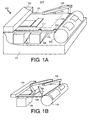
- FIG. 1A shows one embodiment of a mounting device 100.
- the device includes a base 111 and a substantially planar loading table 101 attached to the base 111.
- the base 111 is shown cut-away and details of how the components are coupled to the base are not shown for the sake of clarity.
- Part of the planar loading table is the working surface 107.
- the loading table includes a set of vacuum holes 209 (see FIG. 2) to force printing plate material to be attached to the loading table when a vacuum is applied.
- the vacuum holes are coupled to a vacuum system 106 that can be switched on or off under control of a computer system 105.
- the mounting device further includes a mechanical pick-up system.
- One mechanical pick-up system embodiment includes a set of robotic pick-up arms 109 rotatably coupled to the table 101, either by a direct rotatable connection to the table 101, or, in another embodiment, by a rotatable connection to the base 111 to which the table 101 is connected.
- the apparatus further includes a video detection system that in one embodiment includes a video camera on each pick-up arm 109.
- Each pick up arm 109 has a pick-up mechanism that includes at least one suction cap coupled to the vacuum system 106.
- One pick-up arm 109 is shown in FIG. 1A. In this embodiment, three other pick-up arms are located at locations 117, 119, and 121.
- FIG. 1B shows all four pick-up arms 109.
- the video camera of each pick-up arm is interfaced to the computer system 105 to provide an optical recognition system for a set of locations.
- FIG. 3 shows one embodiment of the robotic pick-up arm 109 in more detail.
- the arm 109 is rotatably coupled to the table, e.g., by being rotatably attached to the base 111.
- a motor 301 and motor control system connected to the computer system 105 provide for the arm to rotate under control of the computer system 105.
- the approximate range of rotation is shown as AA.
- the suction cap pick-up mechanism is shown as 311 and the video camera is shown as 309. Both the suction cap and the camera system are mounted on a head 307 that moves along the arm, also under control of the computer system 105.
- the motion of the head uses a lead screw 305 and a second motor 303 with a control system connected to the computer system 105.
- BB The approximate range of motion along the arm 109 is shown as BB.
- a linear motor provides the motion along of the head along the arm. See US-4,543,615 for a description of a linear motor. US- 4,543,615 is incorporated herein by reference.
- the suction cap of pick-up mechanism 311 is movable towards or away from the loading table under control of the computer system 105.
- the suction caps of the robotic pick-up arms 109 may be positioned to be on top of a desired location on the loading table working surface 107 on which a plate segment was placed, and lowered to make contact or almost make contact with the plate segment.
- the vacuum can then be turned on (under control of the computer system 105) so that the pick-up mechanism's suction cap attaches itself to any plate material on the loading table 101.
- Using the four pick-up arms 109 thus provides a mechanical pick-up system that can pick up by using a plurality of suction caps at a plurality, e.g., up to four locations.
- the vacuum applied to the loading table's vacuum holes 209 is selected to be low enough relative to the vacuum used on the arms' suction caps so that a set of suction caps applied to a plate material segment can remove the plate material segment from the loading table 101.
- One embodiment includes a pneumatic system coupled to each arm's pick-up mechanism 311 to move the pick-up mechanism 311 towards or away from the loading table 101 under control of the computer system 105.
- each pick-up arm 109 is movable towards or away from the loading table 101.
- the computer system 105 can direct the video cameras 309 and the suction caps of the pick-up arms 109 to a set of locations on the working surface 107 of the loading table 101.
- positioning the arm 109 is relative to the loading table surface that provides a frame of reference.
- the device 100 also includes a cutting bridge 103 across the loading table 101 (the y-direction) with a cutting knife mechanism.
- the cutting bridge 103 includes a motor and motor control mechanism that can move the bridge 103 along the loading table 101 on two rails in the x-direction perpendicular to the bridge 103 under control of the computer system 105.
- One such rail 115 is shown in FIG. 1A.
- the bridge 103 further includes a motor and motor control mechanism connected to the cutting knife mechanism to move the cutting knife mechanism along the length of the bridge under control of the computer system 105 so that by a combination of movement of the bridge 103 along the loading table 101 and the cutting knife mechanism along the bridge 103, the computer system 105 can direct the cutting knife mechanism to any location in on the loading table surface.
- a further motor and control system directs the cutting of any plate material placed on the loading table 101.
- One embodiment uses a commercially available cutting loading table system for the cutting bridge 103 and the cutting knife mechanism and all motors and control systems for the bridge 103 and cutting mechanism.
- the commercially available cutting loading table system is the Kongsberg XL cutting loading table range made by Esko-Graphics NV, of Belgium (formerly Barco Graphics NV), the proprietor of the present invention.
- a brochure describing the Kongsberg XL cutting loading table is available in the Web at http://unix.barco.com/graphics/kongsberg/XLloading tables.htm and incorporated herein by reference.
- the control system software of the Kongsberg XL is included in computer system 105.
- Cutting information may be transferred to the cutting loading table control system to control the cutting of a sheet of plate material placed on the loading table 101.
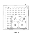
- FIG. 2 shows a top view of the loading table 101 including the working surface 107 within the dashed lines.
- Two of the vacuum holes are shown as having reference numeral 209.
- the loading table 101 includes two alignment edges 203 and 205 in the x- and y-directions, respectively used as registration guides.
- the alignment edges 203, 205 provide for rapidly aligning the sheet so that there is approximate registration relative to the loading table frame.
- Such approximate registration for example, positions a sheet to within 1 mm in one or both of the x and y-directions relative to the positions of the alignment edges 203, 205, and to less than 2 degrees error in rotation.
- FIG. 1 positions a sheet to within 1 mm in one or both of the x and y-directions relative to the positions of the alignment edges 203, 205, and to less than 2 degrees error in rotation.
- the sheet 2 shows a flexographic plate sheet 211 positioned against the alignment edges 203, 205.
- the dashed lines 215 show a cutting path for the cutting knife.
- the sheet 211 shown has four imaged segments. Each segment includes four register marks such as mark 217. On each segment, the dotted lines such as line 213 show the locations where the four suction caps of the pick-up mechanisms 311 on the four arms 109 are positioned to pick up and move the plate segments after cutting (see below).
- the set of printing plate segments on the sheet 211 is maintained on the working surface 107 by the vacuum being turned on to the vacuum holes 209.
- the loading device 100 further includes a clamped cylindrical drum 113 that can rotate around its axis.
- the axis of rotation is parallel to the y-direction.
- the drum 113 is adapted to fit a plate carrier for mounting flexographic plate material thereon.
- the plate carrier is mounted on the drum 113.
- a sleeve is mounted on the drum 113, or a mylar sheet is rolled onto the drum 113, and so forth.
- the drum system includes one or more motors and an associated motor control system coupled to the computer system 105. Rotation of the drum 113, i.e., of the plate carrier, is controlled by software in computer system 105.
- the working surface 107 of the loading table 101 is approximately 90 cm (in the x-direction) by 120 cm wide (in the y-direction).
- a load device may be used, for example, for printing cylinders of up to 120 cm in width.
- Such cylinders may be used, for example, for high quality printing of packaging material such as flexible packaging and folded cartons.
- a second embodiment accommodates printing cylinders of up to 240 cm in width. In such a case, the working surface 107 is approximately 160 cm (in the x-direction) by 240 cm wide (in the y-direction).
- the computer system 105 includes a user interface.
- the computer system also includes the necessary control logic interfaced to the various motor drives and motor control systems, to the cutting knife, to the vacuum system 106, and to the video cameras 309 such that the combination of a video camera 309, interface, and software on computer system 105 forms an optical recognition system.
- the mounting device 100 Operation of the mounting device 100 is described herein for the case of flexographic plate segments being mounted onto an adhesive sleeve such as a McDermid Twinlock sleeve (MacDermid Printing Solutions, LLC, Atlanta, GA).
- the mounting system is easily adapted to other printing plates, not just flexographic plates, and to other types of printing plate carriers.
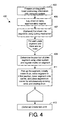
- FIG. 4 shows a flow chart of one embodiment of a method 400 of mounting plate segments using an embodiment of the mounting device 100.
- the method starts at step 403 with producing printing plate sheets 211.
- This can use any conventional method and results in imaged sheets of flexographic plate.
- Each sheet 211 can contain one or multiple parts (segments) of one or multiple separations.
- the printing plate sheets 211 are produced in a manner that reduces waste using the imaging method described in above-mentioned incorporated-by-reference US-2003/053138.
- the imaging method described in this document includes processing full-format screened data in a computer to identify zones that contain printable information. The zones are packed, imaged onto a set of printing plate sheets 211, e.g., one sheet 211 for each separation so that each sheet 211 may be cut into flexographic plate segments.
- the method includes imaging a set of register marks for each segment. US-2003/053138 is incorporated herein by reference.
- the positioning data for the segments is transferred to computer system 105.
- the computer system 105 contains information on where each printing plate segment is to be placed on a printing sleeve (the respective final position) and where each segment is located in the printing plate sheet 211 prior to cutting.
- a step 405 the sheet 211 of printing plate material containing the flexographic plate segments is laid on the loading table 101 against the alignment edges 203 and 205 (see FIG. 2). In this manner, plate can be approximately registered with respect to the mounting system, e.g., with less than 1 mm error in position and less than 2 degrees error in rotation.
- the vacuum system 106 is turned on so that the vacuum applied to the vacuum holes 209 maintains the sheet in position on the working surface 107.
- the cutting knife mounted on cutting bridge 103 cuts the sheet 211 into individual segments along a cutting path (dashed lines 215 in FIG. 2).
- the cutting path 215 is determined by the computer system 105 using information obtained during the imaging and loaded into computer system 105.
- a plurality, denoted N of flexographic plate segments are on the loading table 101 positioned at their initial location, i.e., approximately registered.
- steps 409 and 411 are executed for each plate material segment sequentially until there are no more segments.
- the steps are described for one plate segment, and are identical for the other segments.
- the location of the flexographic plate segment is determined using the video detection system.
- the computer system 105 includes information on the relative locations of the register marks 217 on the segment relative to the sheet 211 of plate material, hence the approximate location of the flexographic plate segment is known.
- the segment includes a set of register marks 217.
- the register marks 217 each have a cross form and are positioned near the outside border of the segment of plate material. The locations of such a mark 217 is detected. The corresponding location of the register mark 217 on the final printing plate carrier is stored in the computer system105.
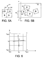
- FIG. 2 shows a simple example of four plate segments that each includes an image and four register marks 217.
- FIG. 5A shows the same segments in their initial position.
- step 409 the pick-up arms 109 move to positions such that each arm's video camera 309 is approximately over a register mark 217.
- each register mark 217 up to the number of pick-up arms 109 ⁇ is in a video camera's field of view.
- the video information is input to the computer system 105 and the register mark 217 is recognized in order to determine the exact position of the register mark 217. Because step 405 positions the segments approximately, e.g., to within one mm in each orthogonal direction, the video registering system can limit its search in a small region around theoretical position.
- FIG. 6 shows the region around a single register mark 217.
- a search is made over an area FGHJ between x MIN and x MAX in the x-direction, and y MIN and y MAX in the y-direction.
- the distances (x NAX -x MIN ) and (y MAX- y MIN ) are related by the accuracy of loading the sheet 211, e.g., the register mark length +2 mm in the x- and y-directions, respectively.
- the mark 217 preferably consists of two crossed lines, with the register point being the intersection of the lines.
- the register marks 217 are located far enough away from any image on the plate such that no image data is present within the register mark search region FGHJ.
- image of the region around the register mark 217 is digitized and analyzed by computer system 105.
- the edge locations are determined in one embodiment by a simple edge enhancement and scanning process for edge detection.
- the enhanced image data is scanned in the x- and y-directions to determine a set of x-values and y-values for the edges in each register mark 217.
- Each x-position is scanned up (increasing y) and down (decreasing y) to yield a pair of y-values for the edge.
- the average of the y-values for scanning up and down is determined as the register mark location.
- one or two edge locations are determined at each x-value.
- one or two edge locations are determined for each y-value.
- two lines AB and CD are determined (see FIG. 6).
- the intersection of the two lines, shown as E, can then be determined for each register mark 217.
- the register mark data is in the form of coordinates x R and y R .
- One embodiment assumes no deformation, e.g., stretching of the plate segment occurs.
- An alternate embodiment assumes deformation can occur.
- the locations of more than two register marks 217 are used to determine the deformation.
- each arm 109 is moved so that each suction cap is approximately at the location of a register mark. This is preferred because the region around each register mark 217 is known to be free of printing information, so is flat. This permits the suction cap to pick up the plate without damaging the plate.
- the dimensions of the block on which the pick-up mechanism 311 and video camera 309 are mounted is such that the minimum distance between the pick-up suction caps of any two arms 109 is about 10 cm.
- the minimum distance between the pick-up suction caps of any two arms 109 is about 10 cm.
- four register marks 217 may be used, and the all four pick-up arms 109 can be used to pick up the segment.
- For smaller segments as few as a single pick-up arm 109 may be used, and typically two or more pick-up arms 109 are used.
- a step 411 the suction caps of the pick-up mechanisms 311 are moved over the register marks 217 and lowered.
- the vacuum is turned on for each pick-up mechanism 311 on each arm 109 so that the segment is locked onto the set of arms 109.
- the vacuum applied to the pick-up arm's suction cap is selected to produce a force higher than that applied at the vacuum holes 209 on the loading table surface.
- the set of pick-up arms 109 together now pick up the segment of printing plate by lifting the suction caps with the vacuum on.
- the plate is typically kept horizontal.
- the set of arms 109 together move under computer control to carry the plate segment to the correct position on the drum 113 on which a printing plate carrier is held.
- the paths for the four arms 109 are determined on the computer system 105 so that each register mark 217 ends up at the correct position on the carrier.
- Each path includes translation of the arms 109 in a manner that (1) rotates the segment to the correct orientation, and (2) moves the so-called "roll-off point" on the segment to the position immediately above the axis of rotation of the drum 113 at the correct y-position of the roll-off point.
- the roll-off point is the point of the segment that would be the last point touching the drum surface if the plate segment was correctly positioned and was to be removed in a first direction, e.g., counterclockwise.
- FIG. 5A shows the exposed plate 211 (FIG. 2) after cutting.
- FIG. 5B shows the carrier 511 unrolled with the plate segments of plate 211 correctly placed.
- FIG. 5B shows exaggerated rotation of the segments to the correct orientation.
- the roll-off point on any segment when the first rotation direction is counterclockwise is the point on the segment with the least x-value on the unrolled carrier 511.
- the counterclockwise roll-off point is the top left-hand corner 503.
- the motion of the arms 109 is such that point 503 is moved to be on top of the axis of the drum 113 at the correct y-position shown as distance 515.
- segment 509 that has an "A.”
- the path of the arms 109 is calculated so that segment 509 is rotated to its correct orientation and so that point 507 (the counterclockwise roll-off point) is moved to be above the axis of rotation at the correct final y-position of point 507.
- the rotation of the drum 113 in the first direction also is determined so that the roll-off point is located above the axis of rotation.
- the paths are calculated so that the segment of plate material is not stretched, i.e., the distance between the suction caps on the pick-up arms 109 is maintained constant throughout the motion.
- the distance between the suction caps is modified during the motion to correct for any stretching or other deformation that may have been determined.
- the drum 113 is rotated in the first direction, e.g., counterclockwise so that the roll-off point is above the axis of rotation, and the arms 109 are moved to rotate the segment to the correct orientation and move the segment so that the roll-off point is above the axis of rotation of the drum 113 at the correct position along the rotation axis.
- the plate is now brought down until the roll-off point touches the drum 113.
- the roll-off point e.g., point 503 in the case of segment 505 now sticks to the carrier 511 on the drum 113.
- the whole carrier 511 is adhesive.
- the drum 113 is now rotated in the direction such that the segment is laid down on the surface of the carrier 511, e.g., clockwise while the arms 109 simultaneously move so that the segment is translated at a speed that is matched to the rotation of the drum 113.
- the rotation of the drum 113 and simultaneous translation of the segment continues until the whole segment adheres to the carrier 511 on the drum 113.
- the vacuum is released as each suction cap passes over the axis of rotation of the drum 113.
- the motion of the arms 109 for each segment including the picking up of each segment from the working surface 107 of the loading table 101, the rotation and translation of the segment to the intermediate position so that the roll-off point is above the rotation axis, the initial rotation of the drum 113, the lowering of the segment onto the drum 113, and the rotation of the drum 113 simultaneous with the motion of the arms 109 and release of the suction caps is controlled by executing real-time control software on computer system 105 based on the determined paths and motions.
- the method repeats steps 409 and 411 for each segment that is to be mounted on the plate carrier.
- the one carrier may include segments from more than one sheet 211 of plate material. In such a case, step 405 and 407 are repeated for any additional sheets 211 needed for the one plate carrier 511.
- the method results in a plate carrier 511, e.g., a sleeve in the drum carrying the segments correctly placed for a separation.
- a plate carrier 511 e.g., a sleeve in the drum carrying the segments correctly placed for a separation.
- the newly created printing plate carrier 511 is used to make an impression on a sheet of substrate, e.g., paper mounted on a second drum, or in an alternate embodiment, on a second loading table at the other side of the printing drum.
- a sheet of substrate e.g., paper mounted on a second drum, or in an alternate embodiment, on a second loading table at the other side of the printing drum.
- One embodiment of optional step 413 includes inking the plate with the corresponding ink. Such inking may be carried out manually with a hand roller.
- an automatic inking system may be used. Automatic inking systems are known in the art. For example, proofing systems for flexographic plates that include automatic inking systems are known in the art, and such an automatic inking system may be adapted to use in the mounting system described herein.
- the plate carrier ⁇ the drum sleeve or mylar sheet the drum ⁇ is removed from the device 100 and is ready for use in printing.
- the next printing plate carrier can now be loaded.
- a new plate sheet can be loaded or the remainder of the previous sheet can be used, as required.
- a mounting device 700 comprising a base 701 is shown in FIG. 7.
- the drum 113 of FIG. 1 is replaced by a flat surface 707 on an extension table 703 onto which the sheet carrier can be loaded.
- the surface 707 includes vacuum holes coupled to the vacuum to hold the sheet onto the surface.
- step 411 includes applying an adhesive after the plate is lifted from the loading table 101 and before the plate segment is lowered onto the plate carrier 511.
- step 411 includes automatically applying the adhesive.
- An embodiment of the mounting system includes a gluing system that uses a gluing roller coupled to the computer system 105 and located between the plate sheet location and the drum 113 so that adhesive is applied under control of the computer system 105 after the plate is lifted from the loading table 101 and before the plate segment is lowered onto the plate carrier 511.
- Another version of the method includes applying adhesive by hand.
- the mounting device is suitable for multi-ink printing of screened images.
- the screen directions need to be accurate relative to each other.
- the plate segments are imaged in the same direction.
- the packing is such that all plate segments are oriented the same way, or rotated ⁇ 90°.
- each segment needs to be rotated either by a relatively small amount, e.g., in the range of-3 to +3 degrees, to account for misplacement on the table, or by an angle close to 90 degrees, e.g., 87 to 93 degrees or -93 to -87 degrees.
- the embodiments shown in FIGS. 1A and 1B are aimed at rotating by a small angle. If rotation by an additional ⁇ 90° is desired, the individual pieces would need to be rotated manually.
- Each of the pickup arms 109 then, in the step 409, determine the position of plate segment using the video system to detect the position of the register marks 217 on the segment.
- FIG. 8 shows an alternate pick-up arm system 800 for the mounting device 100, 700.
- the mounting device 100, 700 uses only a single pick-up arm system 800.
- the system 800 includes an arm 801 rotatably mounted to the table, e.g., by being rotatably attached to the base 111.
- a motor 807 and motor control system connected to the computer system 105 provide for the arm 801 to rotate under control of the computer system 105.
- a head 809 moves along the arm 801 using a lead screw 803 and a second motor 805 with a control system connected to the computer system 105.
- An alternate embodiment uses a linear motor for the motion of the head 809.
- An assembly having four limbs 813, 823, 825, and 827 at forming an "X" is rotatably attached to the head 809 and can rotate using a motor 811 coupled to the computer system 105.
- each of the limbs 813, 823, 825, and 827 is identical.
- Limb 813 includes a head 815 on which is mounted a suction cap pick-up mechanism and a video camera.
- the head 815 is movable along the limb 813, also under control of the computer system 105.
- the motion of the head 815 uses a lead screw 817 and yet another motor (not represented in the drawings), with a control system connected to the computer system 105.
- An alternate embodiment has head 809 mounted on a bridge (not represented in the drawings) across the loading table (the y-direction) that includes motor and motor control mechanism that can move the bridge along the loading table in the x-direction perpendicular to the bridge under control of the computer system 105 on two rails.
- the head 809 moves along the bridge under control of the computer system 105.
- Both the single arm and single bridge embodiment that includes the head 809 of four limbs 813, 823, 825, and 827 provides for rotating the plate segment any arbitrary angle once the plate segment is picked up.
- An improved embodiment applicable to the single arm and the bridge configurations has pairs of limbs on the head 809 be co-linear, and allows the pairs of limbs to rotate with respect to each other.
- an additional motor and motor control system coupled to the computer system 105 are included to permit co-linear limbs 813 and 823 to rotate independently of co-linear limbs 825 and 827. That provides 4 arbitrary pick up points.
- One embodiment includes a video camera mounted in each pick-up arm.
- the video camera is positioned over a register mark and an image taken and input to the computer.
- the video camera may be a CCD camera, but this aspect the invention does not depend on the type of camera used.
- Software in the computer system then determines the position of the register mark.
- the video detecting system used to detect the position of each segment's the registration marks includes a laser scanner rather than a video camera on each pick-up arm.
- the laser scanner includes a laser source and laser detector. The region around each register mark is optically scanned to determine the location of the lines of each register mark.
- step 405 lays a plurality of printing plate sheets on the loading table 101 at different positions.
- FIG. 1A shows two plate sheets. As long as each of these sheets is laid down with approximate registration so that the computer system 105 knows the approximate position, e.g., to within 1 mm in the x- or y-directions, the different plate segments are handled one by one sequentially, fully under control of the computer system 105, as described above.
- the term computer system is used herein to indicate any device or system for controlling the devices such as the mechanical pick-up system. Thus, the term includes special purpose controllers, and other special purpose devices.
- the system 105 for example, need not even include a traditional computer.
- cylindrical plate carrier is meant a sleeve or a printing cylinder, etc., or a sheet such as a sheet of mylar that has been wrapped around a cylinder.
- rotatably coupled to the loading table includes, for example when applied to a pick-up arm the case that the table is connected to a base and that the pick-up arm is rotatably connected to the base. No direct connection between the table and the arm need occur, although the term includes such a case.
Abstract
A method and apparatus for mounting printing plate segments on a printing
plate carrier comprising accepting positioning data indicative of a set of first positions
and loading the imaged segments onto a working surface of the loading table at
approximately the corresponding first positions. The method further includes, for each
segment, detecting the position of the segment on the table, and using a mechanical
pick-up system to pick up the segment and to carry the segment to a final position on
the carrier. The carrying is via a path determined using the detected position on the
table and the final position. The table's working surface has a set of vacuum holes
coupled to a vacuum system. The mechanical pick up system includes a plurality of
suction caps coupled to the vacuum system to pick up the plate. One version includes a
mechanism for cutting the segments from the sheet.
Description
- This invention relates to the field of printing, and in particular to a method and apparatus for mounting flexographic or letterpress plate segments onto a printing plate carrier.
- Flexography and letterpress use printing cylinders on which printing plates are mounted using different mounting methods. When printing in color, one cylinder is used for each color, i.e., for each color separation.
- Conventional printing uses a single printing plate on the cylinder covering the whole area to be printed. An alternate is using a plurality of segments of plate material mounted on the cylinder. Such a method uses less printing plate material than using a single plate covering the whole area to be printed, and is suitable for flexography and letterpress because flexographic and letterpress plate material is relatively expensive. An economical method for creating plate segments, each containing register marks is described in US-2003/053138.
- A known manual method for mounting the plate segments onto a carrier to produce a cylinder with multiple plate segments includes first producing flat printing plate sheets, cutting the plate segments, and manually mounting the segments onto a printing plate carrier such as a drum, sleeve, or a mylar sheet. Several tools exist to facilitate this operation, e.g., so that the operation is more repeatable. Success is highly dependent on the skill of the operator.
- The manual method includes applying glue to the back of the printing plate segments or making the printing plate carrier adhesive, e.g., by applying glue or by using double sided adhesive tape. The manual method further includes the operator manually aligning register marks on the printing plate segments with marks that have been provided by a mounting apparatus. The operator can use a prior-art mounting apparatus for this. The apparatus helps registering by using a half-transparent mirror or a video screen to display a register mark on top of the image of the plate segments. In all such procedures, an operator manually decides where to mount the plate segment. As a result, the quality of the resulting printing cylinders may vary depending on the skill of the operator. Furthermore, the mounting may take a relatively long time, especially when high precision is required. Furthermore, large plate segments are more difficult to mount than smaller plate segments, mainly because it is difficult for human operators to handle large plate segments.
- An apparatus that helps a human operator to mount printing plate segments onto a printing cylinder is called a manual mounting machine herein, and the mounting method is called a manual mounting method.
- Another prior art method for producing cylinders that include printing plate segments produces the printing cylinders directly. Blank, unimaged plate segments are applied on a cylindrical plate carrier, typically a sleeve, and imaged in a computer-to-plate drum imaging device such as the Esko-Graphics Cyrel Digital Imager (Esko-Graphics NV, Gent, Belgium, the applicant of the present invention). The imaging device is used to directly expose the sleeve carrying the flexographic plate segments. After exposure, the cylindrical plate carrier with the exposed plate segments attached is moved away from the imaging device and processed in round washing equipment. Because the printing plate segments are not removed from the sleeve or printing cylinder for the processing, the image register is maintained throughout the process until printing. The advantage of this method over the more conventional method of manually mounting imaged segments is the improved register and decreased mounting cost. The second method however is less popular than the manual mounting method, mostly because of cost. Producing imaged flat flexographic plate sheets for printing is relatively inexpensive because the equipment is widely available and its cost mostly amortized. There is substantial investment required for exposing flexographic plates "in the round," i.e., on blank segments mounted on cylindrical carriers.
- One of the problems with using a plurality of segments is accurate registration. As a result, imaging on a single sheet is still often used in flexography, even at the cost of the wasted plate material.
- Thus there is a need in the art for an apparatus and method of producing print-ready cylinders by first exposing flat plate materials and cutting the flat plates into segments, while maintaining register accuracy that does not depend on the skill of the operator to the same extent as the known manual method. There further is a need in the art for a mounting device that provides for mounting exposed plate segments onto a plate carrier while maintaining accuracy, such a device being considerably less expensive than a full "in the round" processing unit.
- Described herein is a method and an apparatus for mounting printing plate segments onto a printing plate carrier. In one embodiment, the printing plate carrier is on a cylindrical drum, i.e., is a cylindrical plate carrier, while in another embodiment, the carrier is a sheet laid out on a substantially flat surface that, after mounting, can be placed on a drum.
- The method includes accepting positioning data indicative of a set of first positions and loading the imaged segments onto a working surface of the loading table at approximately the corresponding first positions. The method further includes, for each segment, detecting the position of the segment on the table, and using a mechanical pick-up system to pick up the segment and to carry the segment to a final position on the carrier. The carrying is via a path determined using the detected position on the table and the final position. In one embodiment, the table's working surface has a set of vacuum holes coupled to a vacuum system. The mechanical pick up system includes a plurality of suction caps coupled to the vacuum system to pick up the plate. One version includes a mechanism for cutting the segments from the sheet.
- In one embodiment, the mechanical pick-up system includes one or more pick-up arms. Each arm is rotatably connected to the loading table and has one or more suction caps coupled to the vacuum system. For example, one version has four pick-up arms. Each arm has a head that is movable lengthwise along the arm. The head includes a video camera and a single suction cap coupled to the vacuum system.
- In one embodiment, each imaged plate segment has a plurality of register points. The detecting of the position of the segment detects the register marks. The detecting uses the video detecting system, e.g., the cameras mounted on the arms of the mechanical pick-up system in the version that has such arms. The picking up includes positioning the pick-up system such that the suction caps are close to the detected positions of the register marks, such that the picking up is at pick-up points close to register marks. The carrying of the segment includes initially rotating the cylindrical carrier so that the location on the carrier of the roll-off point of the segment is such that the mechanical pick up system can place the roll-off point of the segment thereon. The roll-off point is a point on the final position of the segment. The method includes carrying the segment such that the segment's roll-off point can be placed on the location on the carrier of the roll-off point, placing the segment's roll-off point onto the roll-off point location on the carrier, and placing the remainder of the segment on the carrier by translating the mechanical pick-up system and simultaneously rotating the cylinder such that the segment ends placed at its final position.
- In one version, no deformation of the segment can occur during the carrying. In another version, the method includes picking up each plate segment at more than two independent points and carrying each segment to a respective final position on the carrier, such that some of the plate segments may need to be deformed to reach their respective final position. For a plate segment that is so deformed, the final position cannot be reached by picking up the plate segment at only two points because of the required deformation of the plate.
- The apparatus includes a computer system to control the various elements and functions such as the motion of the mechanical pick-up system, the detection of position by the video detection system, and the determining of the path for carrying the plate segments.
-
- FIG. 1A shows one embodiment of a mounting device according to an aspect of the invention.
- FIG. 1B shows a partial view of the embodiment of FIG. 1A with a mechanical pick-up system that includes four pick-up arms.
- FIG. 2 shows a top view of the one embodiment of the loading table of the mounting device of FIG. 1A, including the working surface and a sheet of plate material on the surface.
- FIG. 3 shows an embodiment of one of the pick-up arms of the mounting device of FIG. 1A.
- FIG. 4 shows a flow chart of one embodiment of a method of mounting plate segments on a plate carrier.
- FIG. 5A shows a sheet of plate material with cut segments of plate material in an initial position.
- FIG. 5B shows the plate carrier unrolled with the segments of FIG. 5A after mounting at the correct positions.
- FIG. 6 shows the region around a single register mark according to an embodiment of the invention.
- FIG. 7 shows an alternate embodiment of the mounting device that mounts onto a laid out sheet such as a mylar sheet.
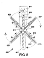
- FIG. 8 shows an alternate embodiment of a mechanical pick-up system that has a single pick-up arm including a head on which are mounted four limbs with each limb having a movable head with a camera system and suction cap thereon.
-
- Described herein is a method for mounting imaged printing plate segments onto a printing plate carrier, and an apparatus for such mounting. The method and apparatus can be used to create cylindrical plate carriers such as printing drums, cylindrical printing sleeves or mylar sheets that may be wrapped around a printing drum. The plate carriers contain segments of printing plate material, mounted such that the plate segments are registered with respect to each other on the same carrier, and such that when a set of cylindrical plate carriers is used to print a set of inks onto the same substrate, the plate segments on one carrier are registered relative to the plate segments on the other cylindrical plate carriers.
- FIG. 1A shows one embodiment of a mounting
device 100. The device includes abase 111 and a substantially planar loading table 101 attached to thebase 111. Thebase 111 is shown cut-away and details of how the components are coupled to the base are not shown for the sake of clarity. Part of the planar loading table is the workingsurface 107. The loading table includes a set of vacuum holes 209 (see FIG. 2) to force printing plate material to be attached to the loading table when a vacuum is applied. The vacuum holes are coupled to avacuum system 106 that can be switched on or off under control of acomputer system 105. - The mounting device further includes a mechanical pick-up system. One mechanical pick-up system embodiment includes a set of robotic pick-up
arms 109 rotatably coupled to the table 101, either by a direct rotatable connection to the table 101, or, in another embodiment, by a rotatable connection to the base 111 to which the table 101 is connected. The apparatus further includes a video detection system that in one embodiment includes a video camera on each pick-uparm 109. Each pick uparm 109 has a pick-up mechanism that includes at least one suction cap coupled to thevacuum system 106. One pick-uparm 109 is shown in FIG. 1A. In this embodiment, three other pick-up arms are located atlocations arms 109. The video camera of each pick-up arm is interfaced to thecomputer system 105 to provide an optical recognition system for a set of locations. - FIG. 3 shows one embodiment of the robotic pick-up
arm 109 in more detail. Thearm 109 is rotatably coupled to the table, e.g., by being rotatably attached to thebase 111. Amotor 301 and motor control system connected to thecomputer system 105 provide for the arm to rotate under control of thecomputer system 105. The approximate range of rotation is shown as AA. The suction cap pick-up mechanism is shown as 311 and the video camera is shown as 309. Both the suction cap and the camera system are mounted on ahead 307 that moves along the arm, also under control of thecomputer system 105. In one embodiment, the motion of the head uses alead screw 305 and asecond motor 303 with a control system connected to thecomputer system 105. The approximate range of motion along thearm 109 is shown as BB. In another embodiment, a linear motor provides the motion along of the head along the arm. See US-4,543,615 for a description of a linear motor. US- 4,543,615 is incorporated herein by reference. - The suction cap of pick-up
mechanism 311 is movable towards or away from the loading table under control of thecomputer system 105. In this manner, under computer control, the suction caps of the robotic pick-uparms 109 may be positioned to be on top of a desired location on the loadingtable working surface 107 on which a plate segment was placed, and lowered to make contact or almost make contact with the plate segment. The vacuum can then be turned on (under control of the computer system 105) so that the pick-up mechanism's suction cap attaches itself to any plate material on the loading table 101. Using the four pick-uparms 109 thus provides a mechanical pick-up system that can pick up by using a plurality of suction caps at a plurality, e.g., up to four locations. The vacuum applied to the loading table's vacuum holes 209 is selected to be low enough relative to the vacuum used on the arms' suction caps so that a set of suction caps applied to a plate material segment can remove the plate material segment from the loading table 101. - One embodiment includes a pneumatic system coupled to each arm's pick-up
mechanism 311 to move the pick-upmechanism 311 towards or away from the loading table 101 under control of thecomputer system 105. In another embodiment, each pick-uparm 109 is movable towards or away from the loading table 101. - Thus the
computer system 105 can direct thevideo cameras 309 and the suction caps of the pick-uparms 109 to a set of locations on the workingsurface 107 of the loading table 101. In one embodiment, positioning thearm 109 is relative to the loading table surface that provides a frame of reference. - The
device 100 also includes a cuttingbridge 103 across the loading table 101 (the y-direction) with a cutting knife mechanism. The cuttingbridge 103 includes a motor and motor control mechanism that can move thebridge 103 along the loading table 101 on two rails in the x-direction perpendicular to thebridge 103 under control of thecomputer system 105. Onesuch rail 115 is shown in FIG. 1A. Thebridge 103 further includes a motor and motor control mechanism connected to the cutting knife mechanism to move the cutting knife mechanism along the length of the bridge under control of thecomputer system 105 so that by a combination of movement of thebridge 103 along the loading table 101 and the cutting knife mechanism along thebridge 103, thecomputer system 105 can direct the cutting knife mechanism to any location in on the loading table surface. A further motor and control system directs the cutting of any plate material placed on the loading table 101. - One embodiment uses a commercially available cutting loading table system for the cutting
bridge 103 and the cutting knife mechanism and all motors and control systems for thebridge 103 and cutting mechanism. The commercially available cutting loading table system is the Kongsberg XL cutting loading table range made by Esko-Graphics NV, of Belgium (formerly Barco Graphics NV), the proprietor of the present invention. A brochure describing the Kongsberg XL cutting loading table is available in the Web at http://unix.barco.com/graphics/kongsberg/XLloading tables.htm and incorporated herein by reference. The control system software of the Kongsberg XL is included incomputer system 105. - Cutting information may be transferred to the cutting loading table control system to control the cutting of a sheet of plate material placed on the loading table 101.
- FIG. 2 shows a top view of the loading table 101 including the working
surface 107 within the dashed lines. Two of the vacuum holes are shown as havingreference numeral 209. In one embodiment, the loading table 101 includes twoalignment edges flexographic plate sheet 211 positioned against the alignment edges 203, 205. The dashedlines 215 show a cutting path for the cutting knife. Thesheet 211 shown has four imaged segments. Each segment includes four register marks such asmark 217. On each segment, the dotted lines such asline 213 show the locations where the four suction caps of the pick-upmechanisms 311 on the fourarms 109 are positioned to pick up and move the plate segments after cutting (see below). The set of printing plate segments on thesheet 211 is maintained on the workingsurface 107 by the vacuum being turned on to the vacuum holes 209. - The
loading device 100 further includes a clampedcylindrical drum 113 that can rotate around its axis. The axis of rotation is parallel to the y-direction. In one embodiment, thedrum 113 is adapted to fit a plate carrier for mounting flexographic plate material thereon. The plate carrier is mounted on thedrum 113. Thus, a sleeve is mounted on thedrum 113, or a mylar sheet is rolled onto thedrum 113, and so forth. The drum system includes one or more motors and an associated motor control system coupled to thecomputer system 105. Rotation of thedrum 113, i.e., of the plate carrier, is controlled by software incomputer system 105. - In one embodiment, the working
surface 107 of the loading table 101 is approximately 90 cm (in the x-direction) by 120 cm wide (in the y-direction). Such a load device may be used, for example, for printing cylinders of up to 120 cm in width. Such cylinders may be used, for example, for high quality printing of packaging material such as flexible packaging and folded cartons. A second embodiment accommodates printing cylinders of up to 240 cm in width. In such a case, the workingsurface 107 is approximately 160 cm (in the x-direction) by 240 cm wide (in the y-direction). - The
computer system 105 includes a user interface. The computer system also includes the necessary control logic interfaced to the various motor drives and motor control systems, to the cutting knife, to thevacuum system 106, and to thevideo cameras 309 such that the combination of avideo camera 309, interface, and software oncomputer system 105 forms an optical recognition system. - Operation of the mounting
device 100 is described herein for the case of flexographic plate segments being mounted onto an adhesive sleeve such as a McDermid Twinlock sleeve (MacDermid Printing Solutions, LLC, Atlanta, GA). The mounting system is easily adapted to other printing plates, not just flexographic plates, and to other types of printing plate carriers. - FIG. 4 shows a flow chart of one embodiment of a
method 400 of mounting plate segments using an embodiment of the mountingdevice 100. - The method starts at
step 403 with producingprinting plate sheets 211. This can use any conventional method and results in imaged sheets of flexographic plate. Eachsheet 211 can contain one or multiple parts (segments) of one or multiple separations. In one embodiment, theprinting plate sheets 211 are produced in a manner that reduces waste using the imaging method described in above-mentioned incorporated-by-reference US-2003/053138. The imaging method described in this document includes processing full-format screened data in a computer to identify zones that contain printable information. The zones are packed, imaged onto a set ofprinting plate sheets 211, e.g., onesheet 211 for each separation so that eachsheet 211 may be cut into flexographic plate segments. The method includes imaging a set of register marks for each segment. US-2003/053138 is incorporated herein by reference. - The positioning data for the segments, including the position of the register marks 217 for each segment, the cutting
path 215 for cutting eachsheet 211 of plate material into segments, and the location of the segments on a printing sleeve, is transferred tocomputer system 105. Thus, at the end ofstep 403, thecomputer system 105 contains information on where each printing plate segment is to be placed on a printing sleeve (the respective final position) and where each segment is located in theprinting plate sheet 211 prior to cutting. - In a
step 405, thesheet 211 of printing plate material containing the flexographic plate segments is laid on the loading table 101 against the alignment edges 203 and 205 (see FIG. 2). In this manner, plate can be approximately registered with respect to the mounting system, e.g., with less than 1 mm error in position and less than 2 degrees error in rotation. Once the plate is laid against the alignment edges 203, 205, thevacuum system 106 is turned on so that the vacuum applied to the vacuum holes 209 maintains the sheet in position on the workingsurface 107. - In a
step 407, the cutting knife mounted on cuttingbridge 103 cuts thesheet 211 into individual segments along a cutting path (dashedlines 215 in FIG. 2). The cuttingpath 215 is determined by thecomputer system 105 using information obtained during the imaging and loaded intocomputer system 105. As a result of cutting, a plurality, denoted N of flexographic plate segments are on the loading table 101 positioned at their initial location, i.e., approximately registered. - The following
steps - In a
step 409, the location of the flexographic plate segment is determined using the video detection system. Thecomputer system 105 includes information on the relative locations of the register marks 217 on the segment relative to thesheet 211 of plate material, hence the approximate location of the flexographic plate segment is known. The segment includes a set of register marks 217. In one embodiment, the register marks 217 each have a cross form and are positioned near the outside border of the segment of plate material. The locations of such amark 217 is detected. The corresponding location of theregister mark 217 on the final printing plate carrier is stored in the computer system105. - FIG. 2 shows a simple example of four plate segments that each includes an image and four register marks 217. FIG. 5A shows the same segments in their initial position.
- As part of
step 409, the pick-uparms 109 move to positions such that each arm'svideo camera 309 is approximately over aregister mark 217. Thus, eachregister mark 217 up to the number of pick-uparms 109 ― is in a video camera's field of view. The video information is input to thecomputer system 105 and theregister mark 217 is recognized in order to determine the exact position of theregister mark 217. Becausestep 405 positions the segments approximately, e.g., to within one mm in each orthogonal direction, the video registering system can limit its search in a small region around theoretical position. - FIG. 6 shows the region around a
single register mark 217. For eachregister mark 217, a search is made over an area FGHJ between xMIN and xMAX in the x-direction, and yMIN and yMAX in the y-direction. The distances (xNAX-xMIN) and (yMAX-yMIN) are related by the accuracy of loading thesheet 211, e.g., the register mark length +2 mm in the x- and y-directions, respectively. Themark 217 preferably consists of two crossed lines, with the register point being the intersection of the lines. The register marks 217 are located far enough away from any image on the plate such that no image data is present within the register mark search region FGHJ. - As part of
step 409, image of the region around theregister mark 217 is digitized and analyzed bycomputer system 105. The edge locations are determined in one embodiment by a simple edge enhancement and scanning process for edge detection. The enhanced image data is scanned in the x- and y-directions to determine a set of x-values and y-values for the edges in eachregister mark 217. Each x-position is scanned up (increasing y) and down (decreasing y) to yield a pair of y-values for the edge. The average of the y-values for scanning up and down is determined as the register mark location. Thus one or two edge locations are determined at each x-value. Similarly, one or two edge locations are determined for each y-value. Thus, two lines AB and CD are determined (see FIG. 6). The intersection of the two lines, shown as E, can then be determined for eachregister mark 217. The register mark data is in the form of coordinates xR and yR. - This operation is repeated for each
register mark 217 of each segment to determine the coordinates of eachregister mark 217. As a result, the position of the plate is known, needing only the coordinate of oneregister mark 217. Once the location of asecond register mark 217 is known, the rotation of the plate segment also is known. - One embodiment assumes no deformation, e.g., stretching of the plate segment occurs. An alternate embodiment assumes deformation can occur. The locations of more than two
register marks 217 are used to determine the deformation. - Once the locations of the register marks 217 of the segment are determined, up to four suction caps are lowered to pick up the segment. In one embodiment, each
arm 109 is moved so that each suction cap is approximately at the location of a register mark. This is preferred because the region around eachregister mark 217 is known to be free of printing information, so is flat. This permits the suction cap to pick up the plate without damaging the plate. - Referring again to FIG. 2, in one embodiment, the dimensions of the block on which the pick-up
mechanism 311 andvideo camera 309 are mounted is such that the minimum distance between the pick-up suction caps of any twoarms 109 is about 10 cm. Thus, segments of any shape that are wider and taller than 10 cm, fourregister marks 217 may be used, and the all four pick-uparms 109 can be used to pick up the segment. For smaller segments as few as a single pick-uparm 109 may be used, and typically two or more pick-uparms 109 are used. - Thus, in a
step 411, the suction caps of the pick-upmechanisms 311 are moved over the register marks 217 and lowered. The vacuum is turned on for each pick-upmechanism 311 on eacharm 109 so that the segment is locked onto the set ofarms 109. Recall that the vacuum applied to the pick-up arm's suction cap is selected to produce a force higher than that applied at the vacuum holes 209 on the loading table surface. Thus a set of suction caps applied to a plate material segment can remove the plate material segment from the loading table 101 after the vacuum is turned on. - The set of pick-up
arms 109 together now pick up the segment of printing plate by lifting the suction caps with the vacuum on. The plate is typically kept horizontal. The set ofarms 109 together move under computer control to carry the plate segment to the correct position on thedrum 113 on which a printing plate carrier is held. - The paths for the four
arms 109 are determined on thecomputer system 105 so that eachregister mark 217 ends up at the correct position on the carrier. Each path includes translation of thearms 109 in a manner that (1) rotates the segment to the correct orientation, and (2) moves the so-called "roll-off point" on the segment to the position immediately above the axis of rotation of thedrum 113 at the correct y-position of the roll-off point. The roll-off point is the point of the segment that would be the last point touching the drum surface if the plate segment was correctly positioned and was to be removed in a first direction, e.g., counterclockwise. That is, if thedrum 113 with the segment correctly placed was to be rotated in the first direction, e.g., counterclockwise, the roll-off point would be the first point that would be above the axis or rotation of thedrum 113. FIG. 5A shows the exposed plate 211 (FIG. 2) after cutting. FIG. 5B shows thecarrier 511 unrolled with the plate segments ofplate 211 correctly placed. FIG. 5B shows exaggerated rotation of the segments to the correct orientation. The roll-off point on any segment when the first rotation direction is counterclockwise is the point on the segment with the least x-value on the unrolledcarrier 511. Consider segment 505-the segment with "C". The counterclockwise roll-off point is the top left-hand corner 503. The motion of thearms 109 is such thatpoint 503 is moved to be on top of the axis of thedrum 113 at the correct y-position shown asdistance 515. Similarly, considersegment 509 that has an "A." The path of thearms 109 is calculated so thatsegment 509 is rotated to its correct orientation and so that point 507 (the counterclockwise roll-off point) is moved to be above the axis of rotation at the correct final y-position ofpoint 507. - For each path, the rotation of the
drum 113 in the first direction also is determined so that the roll-off point is located above the axis of rotation. - How to so determine the paths for the simultaneous motion of the
arms 109 is well known in the field of robotics. In the embodiment in which no deformation is assumed, the paths are calculated so that the segment of plate material is not stretched, i.e., the distance between the suction caps on the pick-uparms 109 is maintained constant throughout the motion. In embodiments in which deformation also is corrected for, the distance between the suction caps is modified during the motion to correct for any stretching or other deformation that may have been determined. - Once the paths are determined, for each segment, the
drum 113 is rotated in the first direction, e.g., counterclockwise so that the roll-off point is above the axis of rotation, and thearms 109 are moved to rotate the segment to the correct orientation and move the segment so that the roll-off point is above the axis of rotation of thedrum 113 at the correct position along the rotation axis. The plate is now brought down until the roll-off point touches thedrum 113. Thus, the roll-off point, e.g.,point 503 in the case ofsegment 505 now sticks to thecarrier 511 on thedrum 113. In one embodiment, thewhole carrier 511 is adhesive. Thedrum 113 is now rotated in the direction such that the segment is laid down on the surface of thecarrier 511, e.g., clockwise while thearms 109 simultaneously move so that the segment is translated at a speed that is matched to the rotation of thedrum 113. The rotation of thedrum 113 and simultaneous translation of the segment continues until the whole segment adheres to thecarrier 511 on thedrum 113. The vacuum is released as each suction cap passes over the axis of rotation of thedrum 113. - The motion of the
arms 109 for each segment, including the picking up of each segment from the workingsurface 107 of the loading table 101, the rotation and translation of the segment to the intermediate position so that the roll-off point is above the rotation axis, the initial rotation of thedrum 113, the lowering of the segment onto thedrum 113, and the rotation of thedrum 113 simultaneous with the motion of thearms 109 and release of the suction caps is controlled by executing real-time control software oncomputer system 105 based on the determined paths and motions. - The method repeats
steps sheet 211 of plate material. In such a case,step additional sheets 211 needed for the oneplate carrier 511. - The method results in a
plate carrier 511, e.g., a sleeve in the drum carrying the segments correctly placed for a separation. - In an
optional step 413, the newly createdprinting plate carrier 511 is used to make an impression on a sheet of substrate, e.g., paper mounted on a second drum, or in an alternate embodiment, on a second loading table at the other side of the printing drum. One embodiment ofoptional step 413 includes inking the plate with the corresponding ink. Such inking may be carried out manually with a hand roller. Alternatively, an automatic inking system may be used. Automatic inking systems are known in the art. For example, proofing systems for flexographic plates that include automatic inking systems are known in the art, and such an automatic inking system may be adapted to use in the mounting system described herein. - Once a test print has been made, the plate carrier―the drum sleeve or mylar sheet the drum―is removed from the
device 100 and is ready for use in printing. The next printing plate carrier can now be loaded. A new plate sheet can be loaded or the remainder of the previous sheet can be used, as required. - While one embodiment loads the segments onto a
cylindrical plate carrier 511, such as a sleeve, a printing cylinder, or a mylar sheet rolled onto a drum, another embodiment loads the segments onto a substantially flat sheet, e.g., a mylar sheet that can later be mounted on a cylinder. Such an embodiment of a mountingdevice 700 comprising abase 701 is shown in FIG. 7. Thedrum 113 of FIG. 1 is replaced by aflat surface 707 on an extension table 703 onto which the sheet carrier can be loaded. In one embodiment, thesurface 707 includes vacuum holes coupled to the vacuum to hold the sheet onto the surface. The carrying of each segment using the mechanical pick-up system to the particular segment's corresponding final position on the carrier is then simpler for the case of the laid out sheet carrier because the combined motion of a drum and the pick-up system is not required. - While one embodiment uses an adhesive sleeve such as a McDermid Twinlock sleeve that is adhesive at the time the plate segment is placed on it, an alternate embodiment uses plate segments that are adhesive. One embodiment of
step 411 includes applying an adhesive after the plate is lifted from the loading table 101 and before the plate segment is lowered onto theplate carrier 511. One version ofstep 411 includes automatically applying the adhesive. An embodiment of the mounting system includes a gluing system that uses a gluing roller coupled to thecomputer system 105 and located between the plate sheet location and thedrum 113 so that adhesive is applied under control of thecomputer system 105 after the plate is lifted from the loading table 101 and before the plate segment is lowered onto theplate carrier 511. - Another version of the method includes applying adhesive by hand.
- According to another implementation, only the areas of the
plate carrier 511 that are to receive printing pate segments are made adhesive, thus saving on adhesive material. These areas of the sleeve can be outlined with an inkjet printing system. US-5,846,691 describes how this may be carried out for the case of non-imaged flexographic plates. How to modify the Cusdin, et al. method for the present invention would be straightforward for those skilled in the art. US-5,846,691 is incorporated herein by reference. - One embodiment of the mounting device is suitable for multi-ink printing of screened images. In such a case, the screen directions need to be accurate relative to each other. Thus, in one embodiment of
step 403, the plate segments are imaged in the same direction. The packing is such that all plate segments are oriented the same way, or rotated ±90°. - In one embodiment of
step 411, each segment needs to be rotated either by a relatively small amount, e.g., in the range of-3 to +3 degrees, to account for misplacement on the table, or by an angle close to 90 degrees, e.g., 87 to 93 degrees or -93 to -87 degrees. The embodiments shown in FIGS. 1A and 1B are aimed at rotating by a small angle. If rotation by an additional ±90° is desired, the individual pieces would need to be rotated manually. Each of thepickup arms 109 then, in thestep 409, determine the position of plate segment using the video system to detect the position of the register marks 217 on the segment. - FIG. 8 shows an alternate pick-up
arm system 800 for the mountingdevice device arm system 800. Thesystem 800 includes anarm 801 rotatably mounted to the table, e.g., by being rotatably attached to thebase 111. Amotor 807 and motor control system connected to thecomputer system 105 provide for thearm 801 to rotate under control of thecomputer system 105. Ahead 809 moves along thearm 801 using alead screw 803 and asecond motor 805 with a control system connected to thecomputer system 105. An alternate embodiment uses a linear motor for the motion of thehead 809. An assembly having fourlimbs head 809 and can rotate using amotor 811 coupled to thecomputer system 105. In one embodiment, each of thelimbs limb 813.Limb 813 includes ahead 815 on which is mounted a suction cap pick-up mechanism and a video camera. Thehead 815 is movable along thelimb 813, also under control of thecomputer system 105. In one embodiment, the motion of thehead 815 uses alead screw 817 and yet another motor (not represented in the drawings), with a control system connected to thecomputer system 105. - An alternate embodiment has
head 809 mounted on a bridge (not represented in the drawings) across the loading table (the y-direction) that includes motor and motor control mechanism that can move the bridge along the loading table in the x-direction perpendicular to the bridge under control of thecomputer system 105 on two rails. Thehead 809 moves along the bridge under control of thecomputer system 105. - Both the single arm and single bridge embodiment that includes the
head 809 of fourlimbs - An improved embodiment applicable to the single arm and the bridge configurations has pairs of limbs on the
head 809 be co-linear, and allows the pairs of limbs to rotate with respect to each other. Referring to FIG. 8, an additional motor and motor control system coupled to thecomputer system 105 are included to permitco-linear limbs co-linear limbs - Thus, a method and apparatus has been described that should be more accurate than mounting plate segments with a manual mounting machine. The mounting method and operation of the mounting device depend less on hand operation and operator skill than the manual method. The accuracy is determined by the mechanical precision of movement of the robotic pick-up arm (or bridge in alternate embodiments). State-of-the-art robotics provides movements that are more precise and more repeatable than manual operations.
- Reference throughout this specification to "one embodiment" or "an embodiment" means that a particular feature, structure or characteristic described in connection with the embodiment is included in at least one embodiment of the present invention. Thus, appearances of the phrases "in one embodiment" or "in an embodiment" in various places throughout this specification are not necessarily all referring to the same embodiment. Furthermore, the particular features, structures or characteristics may be combined in any suitable manner, as would be apparent to one of ordinary skill in the art from this disclosure, in one or more embodiments.
- Similarly, it should be appreciated that in the above description of exemplary embodiments of the invention, various features of the invention are sometimes grouped together in a single embodiment, figure, or description thereof for the purpose of streamlining the disclosure and aiding in the understanding of one or more of the various inventive aspects. This method of disclosure, however, is not to be interpreted as reflecting an intention that the claimed invention requires more features than are expressly recited in each claim. Rather, as the following claims reflect, inventive aspects lie in less than all features of a single foregoing disclosed embodiment. Thus, the claims following the Description of the Illustrative Embodiments are hereby expressly incorporated into this Description, with each claim standing on its own as a separate embodiment of this invention.
- It should further be appreciated that although the invention has been described in the context of flexographic plates, the invention is not limited to such contexts and may be utilized in various printing applications and systems, for example in a system that uses other kinds of plates. The method can be used, for example for letterpress plates, rubber plates, and for varnish blankets.
- While one embodiment uses at most four pick-up points, fewer or more pick-up points may be used in alternate embodiments. More than two pick-up points are required for accurate placements of more than two register point that allows for deformation of the segment.
- One embodiment includes a video camera mounted in each pick-up arm. The video camera is positioned over a register mark and an image taken and input to the computer. The video camera may be a CCD camera, but this aspect the invention does not depend on the type of camera used. Software in the computer system then determines the position of the register mark.
- In an alternate embodiment, the video detecting system used to detect the position of each segment's the registration marks includes a laser scanner rather than a video camera on each pick-up arm. The laser scanner includes a laser source and laser detector. The region around each register mark is optically scanned to determine the location of the lines of each register mark.
- While one embodiment holds one plate sheet at a time on the loading table, an alternate embodiment of
step 405 lays a plurality of printing plate sheets on the loading table 101 at different positions. FIG. 1A, for example, shows two plate sheets. As long as each of these sheets is laid down with approximate registration so that thecomputer system 105 knows the approximate position, e.g., to within 1 mm in the x- or y-directions, the different plate segments are handled one by one sequentially, fully under control of thecomputer system 105, as described above. - Reference herein is made to the
computer system 105. The term computer system is used herein to indicate any device or system for controlling the devices such as the mechanical pick-up system. Thus, the term includes special purpose controllers, and other special purpose devices. Thesystem 105, for example, need not even include a traditional computer. - By "cylindrical" plate carrier is meant a sleeve or a printing cylinder, etc., or a sheet such as a sheet of mylar that has been wrapped around a cylinder.
- The term "rotatably coupled to the loading table" includes, for example when applied to a pick-up arm the case that the table is connected to a base and that the pick-up arm is rotatably connected to the base. No direct connection between the table and the arm need occur, although the term includes such a case.
- The terms "includes" and "including" are synonymous with "comprises" and "comprising," respectively.
- Thus, while there has been described what is believed to be the preferred embodiments of the invention, those skilled in the art will recognize that other and further modifications may be made thereto without departing from the spirit of the invention, and it is intended to claim all such changes and modifications as fall within the scope of the invention.
Claims (33)
- A method for mounting printing plate segments on a printing plate carrier, the method comprising:accepting positioning data indicative of a set of first positions, each first position being the position on a loading table of a corresponding plate segment of a set of imaged printing plate segments;loading the set of imaged printing plate segments on the loading table, each at approximately the corresponding first position on the loading table;accepting positioning data indicative of a set of final positions, each final position being the position of a corresponding printing plate segment on the printing plate carrier; andfor each segment of the set of segments, detecting the position of the segment on the loading table; picking up the segment using a mechanical pick-up system; andcarrying the segment using the mechanical pick-up system to the particular segment's corresponding final position on the carrier, the carrying via a path determined using the detected position on the table and the corresponding final position.
- A method as recited in claim 1, wherein the printing plate carrier is a laid out sheet and the carrying of each segment is on to corresponding final position on the laid out sheet.
- A method as recited in claim 1 or 2, wherein the loading table includes a substantially flat working surface that has a set of vacuum holes coupled to a vacuum system, and wherein the loading of the set of imaged printing plate segments loads one or more sheets onto the table, the loading including turning on the vacuum to the vacuum holes so that the set of segments is maintained on the working surface.
- A method as recited in any of the previous claims, wherein the table includes a substantially flat working surface, wherein the set of imaged printing plate segments are on a sheet of plate material, and wherein the loading loads the sheet of plate material onto the loading table surface, the method further comprising:cutting the segments of the set of segments from the sheet using a cutting mechanism, based on cutting paths.
- A method as recited in any of the previous claims, wherein the detecting the position of the segment uses a video camera.
- A method as recited in any of claims 1 to 4, wherein the detecting the position of the segment uses a laser scanner.
- A method as recited in any of the previous claims, wherein each segment includes a plurality of register marks, and wherein the detecting of the position of the segment detects the register marks.
- A method as recited in claim 7, the mechanical pick-up system including a plurality of suction caps coupled to a vacuum system to pick up the plate, wherein the picking up includes positioning the pick-up system such that the suction caps are close to the detected positions of the register marks, such that the picking up is at pick-up points close to register marks.
- A method as recited in any of claims 7 or 8, wherein the carrying the segment is such that each register mark is moved to its correct final position on the carrier, whether or not deformation of the segment occurs during the carrying.
- A method as recited in any of claims 7 to 9, wherein the carrying the segment is such that the segment is not deformed.
- A method as recited in any of claims 1 to 9, comprising picking up each segment at more than two independent points and carrying each segment to a respective final position on the carrier, such that some of the plate segments may need to be deformed to reach their respective final position, wherein, for a plate segment that is so deformed, the final position cannot be reached by picking up the plate segment at only two points because of the required deformation of the plate.
- A method as recited in any of claims 1 or 3 to 11, wherein the plate carrier is cylindrical, and wherein the carrying the segment includes:initially rotating the cylindrical carrier so that the location on the carrier of a roll-off point of the segment is such that the mechanical pick up system can place the roll-off point of the segment thereon, the roll-off point being a point on the final position of the segment,carrying the segment such that the segment's roll-off point can be placed on the location on the carrier of the roll-off point,placing the segment's roll-off point onto the roll-off point location on the carrier, andplacing the remainder of the segment on the carrier by translating the mechanical pick-up system and simultaneously rotating the cylinder such that the segment ends placed at its final position.
- An apparatus for mounting printing plate segments on a printing plate carrier, comprising:means for loading a set of imaged printing plate segments on a loading table, each approximately at a corresponding first position;means for detecting the position of each segment on the loading table;mechanical means for picking up each segment and for carrying the segment to a final position for the segment on the printing plate carrier.
- An apparatus as recited in claim 13, wherein the printing plate carrier is a cylindrical printing plate carrier, the apparatus further comprising:means for rotating the cylindrical printing plate carrier.
- An apparatus as recited in claim 13, wherein the printing plate carrier is in the form of a sheet, the apparatus further comprising:means for holding the carrier laid out substantially flat.
- An apparatus as recited in any of claims 13 to 15, wherein the loading table includes a substantially flat working surface and means for holding the segments on the table surface.
- An apparatus as recited in any of claims 13 to 16, wherein the means for carrying carries using a path determined from the detected position on the loading table for the segment and the corresponding final position on the carrier.
- An apparatus as recited in any of claims 13 to 17, wherein the loading table includes a substantially flat working surface, and wherein the set of imaged printing plate segments are on a sheet of plate material, the apparatus further comprising:means for cutting the segments from the sheet.
- An apparatus as recited in any of claims 13 to 18, wherein the means for picking up each segment uses suction to pick up the segment.
- An apparatus as recited in any of claims 13 to 19, further comprising:a vacuum system; anda set of vacuum holes on the working surface coupled to the vacuum system able to hold the segments on the surface when a vacuum is applied using the vacuum system.
- An apparatus as recited in claim 20, wherein the mechanical means for picking up includes suction caps coupled to the vacuum system, such that the picking up and carrying uses suction.
- An apparatus as recited in any of claims 20 or 21, wherein the mechanical means for picking up includes one or more pick-up arms, each arm rotatably connected to the loading table and having one or more suction caps coupled to the vacuum system.
- An apparatus as recited in claim 22, wherein each pick-up arm includes a video detection system.
- An apparatus as recited in any of claims 22 or 23, wherein the mechanical pick-up system includes a head that moves along a pick-up arm, the arm including a plurality of limbs rotatably connected to the head, each limb having a single suction cap coupled to the vacuum system.
- An apparatus as recited in any of claims 18 to 24, furthermore comprising:means for accepting positioning data indicative of a set of first positions, and for accepting positioning data indicative of a set of final positions, each first position being the position on the loading table of a corresponding plate segment of a set of imaged printing plate segments, each final position being the position of a corresponding printing plate segment on the printing plate carrier;wherein the means for loadin a set of imaged printing plate segments on the loading table comprises means for loading a sheet of plate material containing the set of imaged printing plate segments onto the loading table such that after the loading, each segment is approximately at its corresponding first position on the working surface;and wherein the means for cutting the segments from the sheet are such that the resulting cut segments are maintained at approximately their corresponding first positions.
- An apparatus as recited in any of claims 13 to 25, furthermore comprising a computer system,
wherein the mechanical means for picking up is coupled to the computer system, the mechanical means for picking up including a pick up device, and able to reach a segment of printing plate material on the working surface under control of the computer system, pick up the segment, and carry the segment to a drum;
wherein the means for detecting the position of each segment on the loading table is coupled to the computer system; and
wherein, for each segment of a set of imaged printing plate segments loaded on the working surface at an approximate first position indicated by positioning data available to the computer system, the mechanical means for picking up under control of the computer system is further able to:pick up the segment, andcarry the segment to a final position for the segment on the carrier, the carrying via a path determined using the detected position on the table and positioning data available to the computer system about the final position for the segment. - An apparatus as recited in any of claims 20 to 26, wherein the mechanical means for picking up includes one or more bridges across the loading table movable along the loading table, the bridges each including one or more suction caps movable along the bridge across the loading table coupled to the vacuum system.
- An apparatus as recited in any of claims 13 to 27, wherein each segment includes a plurality of register marks, and wherein the means for detection is to detect the position of the register marks.
- An apparatus as recited in any of claims 13 to 28, comprising means for picking up each plate segment at more than two independent points and carrying each segment to a respective final position on the carrier, such that some of the plate segments may need to be deformed to reach their respective final position, wherein, for a plate that is so deformed, the final position cannot be reached by picking up the plate segment at only two points because of the required deformation of the plate.
- An apparatus as recited in any of claims 13 to 29, wherein the printing plate carrier is one of a printing sleeve or a mylar sheet mounted on a drum.
- An apparatus as recited in any of claims 13 to 30, wherein the printing plate segments are flexographic plate segments.
- An apparatus as recited in any of claims 13 to 30, wherein the printing plate segments are segments of a rubber printing plate.
- An apparatus as recited in any of claims 13 to 30, wherein the printing plate segments are segments of a letterpress plate.
Applications Claiming Priority (2)
| Application Number | Priority Date | Filing Date | Title |
|---|---|---|---|
| US336944 | 2003-01-06 | ||
| US10/336,944 US6823793B2 (en) | 2003-01-06 | 2003-01-06 | Method and apparatus for mounting flexographic plate segments |
Publications (1)
| Publication Number | Publication Date |
|---|---|
| EP1435291A1 true EP1435291A1 (en) | 2004-07-07 |
Family
ID=32507423
Family Applications (1)
| Application Number | Title | Priority Date | Filing Date |
|---|---|---|---|
| EP03029584A Withdrawn EP1435291A1 (en) | 2003-01-06 | 2003-12-22 | Method and apparatus for mounting flexographic plate segments |
Country Status (2)
| Country | Link |
|---|---|
| US (2) | US6823793B2 (en) |
| EP (1) | EP1435291A1 (en) |
Cited By (13)
| Publication number | Priority date | Publication date | Assignee | Title |
|---|---|---|---|---|
| WO2005090079A1 (en) * | 2004-03-23 | 2005-09-29 | Av Flexologic B.V. | Automatic mounting system |
| WO2006120171A3 (en) * | 2005-05-09 | 2007-04-05 | Goss Graphic Systems Ltd | Printing plate unloading apparatus and method |
| EP1952985A2 (en) * | 2007-02-02 | 2008-08-06 | Andrea Franke | Method and device for positioning a printing plate on embossing tools |
| WO2009099541A2 (en) * | 2008-02-05 | 2009-08-13 | Eastman Kodak Company | Reducing waste in imaging flexographic plates |
| EP2127872A1 (en) * | 2008-05-29 | 2009-12-02 | Andrea Franke | Method and device for positioning plates on embossing tools |
| US8051774B2 (en) | 2004-04-29 | 2011-11-08 | Goss Graphic Systems Limited | Printing plate module, printing press, and method of mounting plates |
| NL2005383C2 (en) * | 2010-09-22 | 2012-03-26 | Av Flexologic Bv | DEVICE AND METHOD FOR POSITIONING A PRESSURE PLATE ON A CARRIER. |
| DE102006060464C5 (en) * | 2006-12-19 | 2013-12-24 | Bobst Bielefeld Gmbh | Method of adjusting a roll in a rotary printing machine |
| EP1916102B2 (en) † | 2006-10-23 | 2014-06-25 | Bobst Bielefeld GmbH | Method of adjusting a roller in a rotary printing press |
| EP2397327A3 (en) * | 2010-06-18 | 2015-08-12 | Esko-Graphics Imaging GmbH | Non-printing registration marks on a printing plate |
| ITUB20155488A1 (en) * | 2015-11-11 | 2017-05-11 | Biessse Equipment Solutions S R L | EQUIPMENT AND PROCEDURE FOR THE APPLICATION OF PHOTOPOLYMERS AT A SLEEVE FOR FLEXOGRAPHIC PRINTING |
| WO2017081642A1 (en) * | 2015-11-11 | 2017-05-18 | Biessse Equipment Solutions S.R.L. | An apparatus and process for preparing a flexographic printing sleeve |
| CN111225798A (en) * | 2017-08-24 | 2020-06-02 | 埃斯科绘图成像有限责任公司 | Printing plate segment mounting system and method |
Families Citing this family (17)
| Publication number | Priority date | Publication date | Assignee | Title |
|---|---|---|---|---|
| US7171901B2 (en) * | 2001-10-18 | 2007-02-06 | Kodak Graphic Communications Canada Company | Flexographic printing method |
| US7717040B2 (en) * | 2007-06-05 | 2010-05-18 | Eastman Kodak Company | Plate cutting and imaging with same device |
| SE531852C2 (en) * | 2007-12-17 | 2009-08-25 | Tetra Laval Holdings & Finance | Method of preparing printing forms for flexographic printing and a system as well as processing tables used in the method |
| US8227769B2 (en) * | 2008-05-27 | 2012-07-24 | Esko-Graphics Imaging Gmbh | Curing of photo-curable printing plates with flat tops or round tops |
| US8129091B2 (en) * | 2008-05-28 | 2012-03-06 | E.I. Du Pont De Nemours And Company | Method for preparing a composite printing form using a template |
| JP5119191B2 (en) * | 2009-03-31 | 2013-01-16 | 富士フイルム株式会社 | Printing plate mounting apparatus and printing plate mounting method |
| US8263314B2 (en) | 2009-08-14 | 2012-09-11 | E I Du Pont De Nemours And Company | Method for preparing a composite printing form |
| US8198013B2 (en) | 2010-05-05 | 2012-06-12 | E. I. Du Pont De Nemours And Company | Method for preparing a printing form |
| NL2006897C2 (en) * | 2011-06-06 | 2012-12-10 | Av Flexologic Bv | METHOD AND DEVICE FOR PLACING A PRESSURE PLATE IN ITS REGISTER POSITION. |
| US8950326B1 (en) | 2012-04-19 | 2015-02-10 | Laser Dot Holding B.V. | Method and apparatus for laser ablating an image on a mounted blank printing plate |
| NL2009341C2 (en) * | 2012-08-22 | 2014-02-25 | Color Control B V | DEVICE AND METHOD FOR CORRECTING THE EFFECTS OF A DEROGATION FROM THE POSITION OF A MOVABLE CAMERA IN A POSITIONING DEVICE FOR POSITIONING FLEXIBLE PRESSURE PLATES ON A SUPPORT. |
| CN105188898A (en) * | 2013-03-01 | 2015-12-23 | 利乐拉瓦尔集团及财务有限公司 | A liquid processing mixer and method |
| US9662871B2 (en) * | 2013-07-22 | 2017-05-30 | Leader Engineering-Fabrication, Inc. | Apparatus and method for application of sticky back material |
| EP3971649B1 (en) | 2016-07-21 | 2023-12-27 | Esko-Graphics Imaging GmbH | System and process for mounting a printing plate on a carrier |
| CN112313933B (en) | 2019-05-17 | 2023-05-05 | 埃斯科绘图成像有限责任公司 | System and method for storing related image information in a print job file |
| EP4000932A1 (en) * | 2020-11-19 | 2022-05-25 | Bobst Bielefeld GmbH | Method and apparatus for attaching a printing plate to a printing cylinder |
| CN114834146A (en) * | 2021-02-01 | 2022-08-02 | 嘉兴阿特斯技术研究院有限公司 | Preparation equipment and preparation method of half battery |
Citations (6)
| Publication number | Priority date | Publication date | Assignee | Title |
|---|---|---|---|---|
| US4543615A (en) | 1982-06-04 | 1985-09-24 | Digitized Information Systems Corp., N.V. | Automatic scanning device and its control for opto-mechanical processing applications |
| US5132911A (en) * | 1989-12-27 | 1992-07-21 | Leader Engineering Fabrication, Inc. | Apparatus for mounting and proofing printing plates |
| US5846691A (en) | 1996-07-08 | 1998-12-08 | Polyfibron Technologies, Inc. | Composite relief image printing plates and methods for preparing same |
| US5850789A (en) * | 1997-07-22 | 1998-12-22 | E. I. Du Pont De Nemours And Company | Method and apparatus for mounting printing plates |
| EP0922578A1 (en) * | 1997-11-27 | 1999-06-16 | A.V. Flexologic B.V. | Method and device for positioning printing plates |
| US20030053138A1 (en) | 2001-09-04 | 2003-03-20 | Thomas Klein | Method, apparatus, and computer program for reducing plate material waste in flexography plate making |
Family Cites Families (18)
| Publication number | Priority date | Publication date | Assignee | Title |
|---|---|---|---|---|
| US4611539A (en) * | 1985-09-30 | 1986-09-16 | Carl Ireton | Device and method for the precision mounting of flexible printing plates |
| DE4208179C2 (en) * | 1992-03-12 | 1996-02-29 | Koenig & Bauer Albert Ag | Method and device for the correct alignment and application of clichés on the lateral surfaces of forme cylinders |
| NL9400057A (en) * | 1994-01-13 | 1995-08-01 | J M J Houtstra Holding B V | Fastener. |
| US5666188A (en) * | 1994-11-29 | 1997-09-09 | Napp Systems, Inc. | Printing plate mounting device |
| US6085653A (en) * | 1995-01-13 | 2000-07-11 | Winkle Holding, B.V. | Method for producing printed matter and printing form attachment means for use in the method |
| US5626076A (en) * | 1995-11-09 | 1997-05-06 | Ireton; Robert E. | Printing plate mounting system, physical register record plate and method employing the same |
| US5678487A (en) * | 1995-11-15 | 1997-10-21 | Heidelberg Harris Inc. | Apparatus for mounting flexible plates in a printing unit |
| US5828501A (en) * | 1996-07-02 | 1998-10-27 | Barco Gerber Systems | Apparatus and method for positioning a lens to expand an optical beam of an imaging system |
| US6312872B1 (en) * | 1997-10-24 | 2001-11-06 | Macdermid Graphic Arts | Composite relief image printing plates |
| US5912458A (en) * | 1997-04-18 | 1999-06-15 | Gerber Systems Corporation | Multiple beam scanning system for an imaging device |
| US5974974A (en) * | 1997-07-01 | 1999-11-02 | Polyfibron Technologies, Inc. | Substantially transparent printing blankets and methods for using same |
| JPH11227163A (en) * | 1998-02-13 | 1999-08-24 | Fuji Photo Film Co Ltd | Method for printing |
| US6112664A (en) * | 1998-04-13 | 2000-09-05 | Fuji Photo Film Co., Ltd. | Plate making apparatus with a cutter and punch mechanism formed in one piece |
| US6058839A (en) * | 1998-11-10 | 2000-05-09 | Frazzitta; Joseph R. | Computerized cutting method and apparatus for use in printing operations |
| FR2802465B1 (en) | 1999-12-20 | 2002-10-25 | Rollin Sa | SLEEVE COMPRISING MEANS FOR FIXING PRINTING PLATES AND PROCESS FOR OBTAINING SAME |
| US6397748B1 (en) * | 2000-07-17 | 2002-06-04 | Vacu-Pin Systems, Llc | Vacuum printing plate mounter and registration system |
| US6675712B2 (en) * | 2002-04-05 | 2004-01-13 | Agfa Corporation | Apparatus and method for picking a single printing plate from a stack of printing plates |
| ES2309246T3 (en) | 2003-03-13 | 2008-12-16 | Bieffebi S.P.A. | PRESS TEST TO ASSEMBLE FLEXOGRAPHIC PRINT SHEETS. |
-
2003
- 2003-01-06 US US10/336,944 patent/US6823793B2/en not_active Expired - Lifetime
- 2003-12-22 EP EP03029584A patent/EP1435291A1/en not_active Withdrawn
-
2004
- 2004-08-03 US US10/910,848 patent/US6948432B2/en not_active Expired - Fee Related
Patent Citations (6)
| Publication number | Priority date | Publication date | Assignee | Title |
|---|---|---|---|---|
| US4543615A (en) | 1982-06-04 | 1985-09-24 | Digitized Information Systems Corp., N.V. | Automatic scanning device and its control for opto-mechanical processing applications |
| US5132911A (en) * | 1989-12-27 | 1992-07-21 | Leader Engineering Fabrication, Inc. | Apparatus for mounting and proofing printing plates |
| US5846691A (en) | 1996-07-08 | 1998-12-08 | Polyfibron Technologies, Inc. | Composite relief image printing plates and methods for preparing same |
| US5850789A (en) * | 1997-07-22 | 1998-12-22 | E. I. Du Pont De Nemours And Company | Method and apparatus for mounting printing plates |
| EP0922578A1 (en) * | 1997-11-27 | 1999-06-16 | A.V. Flexologic B.V. | Method and device for positioning printing plates |
| US20030053138A1 (en) | 2001-09-04 | 2003-03-20 | Thomas Klein | Method, apparatus, and computer program for reducing plate material waste in flexography plate making |
Cited By (21)
| Publication number | Priority date | Publication date | Assignee | Title |
|---|---|---|---|---|
| WO2005090079A1 (en) * | 2004-03-23 | 2005-09-29 | Av Flexologic B.V. | Automatic mounting system |
| US7971530B2 (en) | 2004-03-23 | 2011-07-05 | Av Flexologic B.V. | Automatic mounting system for positioning a plate on a carrier |
| US8505452B2 (en) | 2004-04-29 | 2013-08-13 | Goss Graphic Systems Limited | Printing press including plate support member and plate loading module |
| US8051774B2 (en) | 2004-04-29 | 2011-11-08 | Goss Graphic Systems Limited | Printing plate module, printing press, and method of mounting plates |
| WO2006120171A3 (en) * | 2005-05-09 | 2007-04-05 | Goss Graphic Systems Ltd | Printing plate unloading apparatus and method |
| US8550000B2 (en) | 2005-05-09 | 2013-10-08 | Goss Graphic Systems Limited | Printing plate unloading apparatus and method |
| EP1916102B2 (en) † | 2006-10-23 | 2014-06-25 | Bobst Bielefeld GmbH | Method of adjusting a roller in a rotary printing press |
| DE102006060464C5 (en) * | 2006-12-19 | 2013-12-24 | Bobst Bielefeld Gmbh | Method of adjusting a roll in a rotary printing machine |
| EP1952985A2 (en) * | 2007-02-02 | 2008-08-06 | Andrea Franke | Method and device for positioning a printing plate on embossing tools |
| EP1952985A3 (en) * | 2007-02-02 | 2008-12-17 | Andrea Franke | Method and device for positioning a printing plate on embossing tools |
| WO2009099541A3 (en) * | 2008-02-05 | 2009-10-01 | Eastman Kodak Company | Reducing waste in imaging flexographic plates |
| US8009330B2 (en) | 2008-02-05 | 2011-08-30 | Eastman Kodak Company | Method for imaging flexographic plates |
| WO2009099541A2 (en) * | 2008-02-05 | 2009-08-13 | Eastman Kodak Company | Reducing waste in imaging flexographic plates |
| EP2127872A1 (en) * | 2008-05-29 | 2009-12-02 | Andrea Franke | Method and device for positioning plates on embossing tools |
| EP2397327A3 (en) * | 2010-06-18 | 2015-08-12 | Esko-Graphics Imaging GmbH | Non-printing registration marks on a printing plate |
| WO2012039603A1 (en) * | 2010-09-22 | 2012-03-29 | Av Flexologic Bv | Method and device for removably positioning a printing plate on a carrier |
| NL2005383C2 (en) * | 2010-09-22 | 2012-03-26 | Av Flexologic Bv | DEVICE AND METHOD FOR POSITIONING A PRESSURE PLATE ON A CARRIER. |
| ITUB20155488A1 (en) * | 2015-11-11 | 2017-05-11 | Biessse Equipment Solutions S R L | EQUIPMENT AND PROCEDURE FOR THE APPLICATION OF PHOTOPOLYMERS AT A SLEEVE FOR FLEXOGRAPHIC PRINTING |
| WO2017081642A1 (en) * | 2015-11-11 | 2017-05-18 | Biessse Equipment Solutions S.R.L. | An apparatus and process for preparing a flexographic printing sleeve |
| US10889105B2 (en) | 2015-11-11 | 2021-01-12 | Biessse Equipment Solutions S.R.L. | Apparatus and process for preparing a flexographic printing sleeve |
| CN111225798A (en) * | 2017-08-24 | 2020-06-02 | 埃斯科绘图成像有限责任公司 | Printing plate segment mounting system and method |
Also Published As
| Publication number | Publication date |
|---|---|
| US6823793B2 (en) | 2004-11-30 |
| US20040129157A1 (en) | 2004-07-08 |
| US20050005802A1 (en) | 2005-01-13 |
| US6948432B2 (en) | 2005-09-27 |
Similar Documents
| Publication | Publication Date | Title |
|---|---|---|
| US6823793B2 (en) | Method and apparatus for mounting flexographic plate segments | |
| US11559979B2 (en) | Method of printing objects in a pad printing machine in two stages | |
| EP0893254B1 (en) | Method and apparatus for registration mounting printing plates | |
| JP3781941B2 (en) | Printing device | |
| US7171901B2 (en) | Flexographic printing method | |
| US4872407A (en) | Method for the mounting of a flexible printing plate on a cylinder, and apparatus for the execution of the method | |
| EP2428360B1 (en) | Method and mounter for mounting printing plates | |
| EP0811487A2 (en) | Printing plate mounting system and method employing the same | |
| US5439328A (en) | Single-head drill with video attachment | |
| JP2001301124A (en) | Method and apparatus for managing printing color and image data processor used therefor | |
| EP2701910B1 (en) | Method and apparatus for mounting a printing plate | |
| US6058839A (en) | Computerized cutting method and apparatus for use in printing operations | |
| EP1543966B1 (en) | Method and apparatus for detecting the seam of a flexographic printing plate precursor | |
| US20030075257A1 (en) | Flexographic printing method | |
| JPH06182965A (en) | Cream older printing device | |
| JP3112581B2 (en) | Positioning device and printing device | |
| JPS62200356A (en) | Negative film sticking device | |
| JP2003103762A (en) | Patch measuring instrument and printing apparatus having the same incorporated therein | |
| JP4205440B2 (en) | Printing apparatus, printing method, and manufacturing method of liquid crystal display device | |
| JP2733941B2 (en) | Register control device for multicolor printing press | |
| JP2002120357A (en) | Printer equipped with color chart measuring instrument, color chart measuring instrument, and color chart measuring method | |
| JP2002067268A (en) | Multicolor printer having image recorder as well as method for recording image in multicolor printer having image recorder | |
| JP2736334B2 (en) | Film pasting device | |
| JPH032910Y2 (en) | ||
| JPH05275898A (en) | Mounting position correcting device for part mounting apparatus |
Legal Events
| Date | Code | Title | Description |
|---|---|---|---|
| PUAI | Public reference made under article 153(3) epc to a published international application that has entered the european phase |
Free format text: ORIGINAL CODE: 0009012 |
|
| AK | Designated contracting states |
Kind code of ref document: A1 Designated state(s): AT BE BG CH CY CZ DE DK EE ES FI FR GB GR HU IE IT LI LU MC NL PT RO SE SI SK TR |
|
| AX | Request for extension of the european patent |
Extension state: AL LT LV MK |
|
| 17P | Request for examination filed |
Effective date: 20041208 |
|
| AKX | Designation fees paid |
Designated state(s): DE GB |
|
| 17Q | First examination report despatched |
Effective date: 20081120 |
|
| STAA | Information on the status of an ep patent application or granted ep patent |
Free format text: STATUS: THE APPLICATION IS DEEMED TO BE WITHDRAWN |
|
| 18D | Application deemed to be withdrawn |
Effective date: 20090331 |