EP1434637B1 - Verfahren und trennmodul zum abtrennen von partikeln aus einer dispersion, insbesondere von blutkörperchen aus blut - Google Patents
Verfahren und trennmodul zum abtrennen von partikeln aus einer dispersion, insbesondere von blutkörperchen aus blut Download PDFInfo
- Publication number
- EP1434637B1 EP1434637B1 EP02774618A EP02774618A EP1434637B1 EP 1434637 B1 EP1434637 B1 EP 1434637B1 EP 02774618 A EP02774618 A EP 02774618A EP 02774618 A EP02774618 A EP 02774618A EP 1434637 B1 EP1434637 B1 EP 1434637B1
- Authority
- EP
- European Patent Office
- Prior art keywords
- drain channel
- channel
- junction
- separating
- flow
- Prior art date
- Legal status (The legal status is an assumption and is not a legal conclusion. Google has not performed a legal analysis and makes no representation as to the accuracy of the status listed.)
- Expired - Lifetime
Links
Images

Classifications
-
- G—PHYSICS
- G01—MEASURING; TESTING
- G01N—INVESTIGATING OR ANALYSING MATERIALS BY DETERMINING THEIR CHEMICAL OR PHYSICAL PROPERTIES
- G01N15/00—Investigating characteristics of particles; Investigating permeability, pore-volume or surface-area of porous materials
- G01N15/04—Investigating sedimentation of particle suspensions
- G01N15/05—Investigating sedimentation of particle suspensions in blood
-
- A—HUMAN NECESSITIES
- A61—MEDICAL OR VETERINARY SCIENCE; HYGIENE
- A61M—DEVICES FOR INTRODUCING MEDIA INTO, OR ONTO, THE BODY; DEVICES FOR TRANSDUCING BODY MEDIA OR FOR TAKING MEDIA FROM THE BODY; DEVICES FOR PRODUCING OR ENDING SLEEP OR STUPOR
- A61M1/00—Suction or pumping devices for medical purposes; Devices for carrying-off, for treatment of, or for carrying-over, body-liquids; Drainage systems
- A61M1/36—Other treatment of blood in a by-pass of the natural circulatory system, e.g. temperature adaptation, irradiation ; Extra-corporeal blood circuits
- A61M1/3693—Other treatment of blood in a by-pass of the natural circulatory system, e.g. temperature adaptation, irradiation ; Extra-corporeal blood circuits using separation based on different densities of components, e.g. centrifuging
-
- B—PERFORMING OPERATIONS; TRANSPORTING
- B01—PHYSICAL OR CHEMICAL PROCESSES OR APPARATUS IN GENERAL
- B01L—CHEMICAL OR PHYSICAL LABORATORY APPARATUS FOR GENERAL USE
- B01L3/00—Containers or dishes for laboratory use, e.g. laboratory glassware; Droppers
- B01L3/50—Containers for the purpose of retaining a material to be analysed, e.g. test tubes
- B01L3/502—Containers for the purpose of retaining a material to be analysed, e.g. test tubes with fluid transport, e.g. in multi-compartment structures
- B01L3/5027—Containers for the purpose of retaining a material to be analysed, e.g. test tubes with fluid transport, e.g. in multi-compartment structures by integrated microfluidic structures, i.e. dimensions of channels and chambers are such that surface tension forces are important, e.g. lab-on-a-chip
- B01L3/502753—Containers for the purpose of retaining a material to be analysed, e.g. test tubes with fluid transport, e.g. in multi-compartment structures by integrated microfluidic structures, i.e. dimensions of channels and chambers are such that surface tension forces are important, e.g. lab-on-a-chip characterised by bulk separation arrangements on lab-on-a-chip devices, e.g. for filtration or centrifugation
-
- G—PHYSICS
- G01—MEASURING; TESTING
- G01N—INVESTIGATING OR ANALYSING MATERIALS BY DETERMINING THEIR CHEMICAL OR PHYSICAL PROPERTIES
- G01N33/00—Investigating or analysing materials by specific methods not covered by groups G01N1/00 - G01N31/00
- G01N33/48—Biological material, e.g. blood, urine; Haemocytometers
- G01N33/483—Physical analysis of biological material
- G01N33/487—Physical analysis of biological material of liquid biological material
- G01N33/49—Blood
- G01N33/491—Blood by separating the blood components
-
- B—PERFORMING OPERATIONS; TRANSPORTING
- B01—PHYSICAL OR CHEMICAL PROCESSES OR APPARATUS IN GENERAL
- B01L—CHEMICAL OR PHYSICAL LABORATORY APPARATUS FOR GENERAL USE
- B01L2200/00—Solutions for specific problems relating to chemical or physical laboratory apparatus
- B01L2200/06—Fluid handling related problems
- B01L2200/0647—Handling flowable solids, e.g. microscopic beads, cells, particles
-
- B—PERFORMING OPERATIONS; TRANSPORTING
- B01—PHYSICAL OR CHEMICAL PROCESSES OR APPARATUS IN GENERAL
- B01L—CHEMICAL OR PHYSICAL LABORATORY APPARATUS FOR GENERAL USE
- B01L2300/00—Additional constructional details
- B01L2300/08—Geometry, shape and general structure
- B01L2300/0809—Geometry, shape and general structure rectangular shaped
- B01L2300/0816—Cards, e.g. flat sample carriers usually with flow in two horizontal directions
-
- G—PHYSICS
- G01—MEASURING; TESTING
- G01N—INVESTIGATING OR ANALYSING MATERIALS BY DETERMINING THEIR CHEMICAL OR PHYSICAL PROPERTIES
- G01N15/00—Investigating characteristics of particles; Investigating permeability, pore-volume or surface-area of porous materials
- G01N15/04—Investigating sedimentation of particle suspensions
- G01N15/05—Investigating sedimentation of particle suspensions in blood
- G01N2015/055—Investigating sedimentation of particle suspensions in blood for hematocrite determination
-
- G—PHYSICS
- G01—MEASURING; TESTING
- G01N—INVESTIGATING OR ANALYSING MATERIALS BY DETERMINING THEIR CHEMICAL OR PHYSICAL PROPERTIES
- G01N15/00—Investigating characteristics of particles; Investigating permeability, pore-volume or surface-area of porous materials
- G01N15/10—Investigating individual particles
- G01N15/14—Optical investigation techniques, e.g. flow cytometry
- G01N2015/1486—Counting the particles
-
- Y—GENERAL TAGGING OF NEW TECHNOLOGICAL DEVELOPMENTS; GENERAL TAGGING OF CROSS-SECTIONAL TECHNOLOGIES SPANNING OVER SEVERAL SECTIONS OF THE IPC; TECHNICAL SUBJECTS COVERED BY FORMER USPC CROSS-REFERENCE ART COLLECTIONS [XRACs] AND DIGESTS
- Y10—TECHNICAL SUBJECTS COVERED BY FORMER USPC
- Y10T—TECHNICAL SUBJECTS COVERED BY FORMER US CLASSIFICATION
- Y10T436/00—Chemistry: analytical and immunological testing
- Y10T436/25—Chemistry: analytical and immunological testing including sample preparation
- Y10T436/25375—Liberation or purification of sample or separation of material from a sample [e.g., filtering, centrifuging, etc.]
Definitions
- the invention relates to a method for separating particles from a dispersion and a component for carrying out such a method. Since such a component can be used modularly as part of different systems, it is referred to here as a separation module.
- the invention can be used in particular for separating corpuscular components from biological samples, especially from blood.
- the problem arises of partially or completely removing the particles from a dispersion which contains particles dispersed in a carrier medium.
- a particularly important area is analytical methods for determining the concentration of constituents in the blood.
- blood tests can not be performed on whole blood containing the corpuscular components (blood cells). Rather, it is necessary to previously obtain from the whole blood plasma, which is as free as possible of cellular material.
- the invention is also suitable for the treatment of other dispersions, wherein the carrier medium can be not only liquid but also gaseous.
- the invention can also be used in other fields of chemical engineering and the food industry to separate particles from process streams. Further uses are in biotechnological processes (removal and isolation of cell cultures from corresponding dispersions) as well as in the field of wastewater treatment. Without restriction of generality, reference will be made below to the treatment of dispersions in liquids, mainly to the separation of plasma from whole blood.
- centrifugation techniques have been used to obtain plasma for blood tests by separating the cellular components.
- they are not suitable for modern miniaturized tests. This is especially true for the so-called near-patient diagnostics, in which a small and compact analysis element (for example in the form of a test strip) contains all necessary reagents and other means for the performance of the test, so that only the sample liquid are brought into contact with the analysis element in order to be able to change after a short time by means of a change that can be physically detected on the analysis element (in particular a color change or a change in an electrical measured variable). to determine the desired analytical result visually or with the aid of an evaluation device.
- a small and compact analysis element for example in the form of a test strip
- microchannels are produced by etching in a silicon substrate.
- the separation of the blood cells takes place in a so-called barrier channel (barrier channel) whose depth is less than 0.1 ⁇ m, so that the blood cells can not flow through the barrier channel.
- barrier channel barrier channel
- the required inflow channels and the blocking channel are produced in two consecutive production steps.
- the required, extremely small depth of the barrier channel of less than 0.1 microns is determined by the duration of the etching process in an etching bath. In view of the required high reproducibility of this manufacturing process is very difficult and expensive.
- the object of the invention is to make possible the separation of particles from a dispersion while avoiding the disadvantages described above with a separation module which can be produced simply and inexpensively.
- the separation module should preferably be a so-called "disposable" intended for single use and be suitable in particular for the generation of small amounts of plasma (less than 10 .mu.l , in particular less than 5 .mu.l ) for miniaturized tests.
- the object is achieved by a method for separating particles from a fluid dispersion, in particular for separating corpuscular components from biological samples, especially blood, by means of a separation module with a substrate having flow channels in the form of groove-shaped depressions in a surface of the substrate, comprising an inflow channel for supplying the dispersion to a branch, a first effluent channel for discharging reduced particle concentration fluid away from the branch, and a second effluent channel for discharging increased particle concentration fluid away from the branch, the fluid in the second effluent channel being so much flows faster than in the first spillway, that the dispersed particles at the branch due to the different flow rate preferably continue to flow in the second spillway.
- the filtration methods hitherto used for the purposes of the invention are based on steric selection, ie on the fact that the particles to be separated are retained because the pores of the filter medium are smaller than the diameter of the particles.
- the pore diameter of the filter medium in particular because of the easy deformability of the erythrocytes may be at most about 1 ⁇ m .
- selection is based on a completely different principle: different local particle flow velocities in different flow paths of the liquid flow in the separation module result in shear stresses which cause the particles at the branch to preferentially continue to flow into the second flow channel at the higher flow rate.
- the first drain channel with the lower flow rate contains a reduced particle concentration.
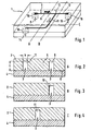
- the separation module 1 shown in Figures 1 to 4 consists essentially of a channel part 2 with flow channels 3 and a cover part 4.
- the flow channels 3 in Form of microscopic groove-shaped depressions in a surface 6 of the substrate 5 is generated.
- the channels are shown in the figures, especially in Figures 2 and 4 in greatly exaggerated size.
- Their width b is typically less than 150 .mu.m, with channel widths of less than 100 .mu.m , preferably less than 50 .mu.m , having proved particularly suitable for plasma recovery.
- the preferred dimensions are so far beyond the wavelength range of visible light that the required structures in the surface 6 of the substrate 5 can be readily produced by photolithographic techniques as described in US Pat the production of electronic chips are known.
- the width b of the channels is at least about 5 microns.
- an inlet 8 is whole blood (or other dispersion to be separated from the particles) fed into the separation module 1 and fed via an inlet channel 9 of a branch 10, at which the liquid flow into a first effluent channel 11 and into a second effluent 12th branched.
- the liquid flowing in the discharge channels 11 and 12 is removed from the separation module 1 via outlets 14 and 15, respectively.
- the inlets and outlets are formed in the case shown by existing in the cover part 4 boreholes 16 to which suitable lines, such as plastic hoses can be connected.
- the liquid in the second outflow channel 12 flows much faster than in the first outflow channel 11, that at the branching 10 the dispersed particles preferably continue to flow in the second outflow channel due to the different flow rate.
- the depths t of the channels 9, 11, 12 are greater than the width b at least in the channel sections immediately adjacent to the branching 10.
- Particularly preferred is an embodiment in which the depths are at least the inflow channel 9 and the plasma channel 11 in the immediately adjacent to the branch 10 channel section are the same size. This is especially preferred for all channels 9, 11, 12 connected to the branch
- the smallest cross-sectional dimension of the plasma channel is at least 5 ⁇ m and at most 150 ⁇ m , with values smaller than 100 ⁇ m , in particular smaller than 50 ⁇ m , being particularly preferred.
- the flow resistance of the plasma channel 11 should generally be higher than the flow resistance of the waste channel 12. This is preferably at least partially effected by the plasma channel being longer than the waste channel. This is advantageous because the flow resistance of the discharge channels 11, 12 can be adjusted more easily and precisely by a corresponding adjustment of their length than by means of a corresponding dimensioning of the cross section.
- the depth t of the discharge channels 11, 12 is the same over at least part of their length, preferably over their entire length.
- the depth of the inflow channel 9 also coincides with the (same) depth of the discharge channels 11, 12.
- the flow channels 3 are preferably the same width over almost their entire length, but it has proved to be advantageous if at least the inflow channel 9 and the waste channel 12 in the region of the inlet 8 and the outlet 15 are designed so that sharp corners, could be damaged by the erythrocytes avoided.
- Fig. 1 an oblique course of the walls of said channels 9 and 12 is indicated in this area.
- Fig. 6 is a graph of experimental data illustrating the dependence of the separation effect on the relation of the flow velocity in the drainage channels. They were obtained with a separation module according to Fig. 1, wherein the inflow channel 9 and the waste channel 12 were each 32 microns wide and 32 microns deep. The plasma channel 11 was 16 ⁇ m wide and 32 ⁇ m deep. The flow per unit time in the inflow channel 9 ranged between 0.01 and 0.5 ⁇ l / min. On the abscissa, the relation of the flow velocity v P in the plasma channel 11 to the flow velocity v F in the feed channel (F) is plotted. The ordinate shows the corresponding relation of the particle numbers N P to N F.
- the experiments were diluted at a ratio of 1: 5 Blood performed to make the erythrocytes more visible.
- the velocities v P and v F were derived from the video observation of the erythrocytes flowing in the central current path.
- the particle counts were also determined from the video data.
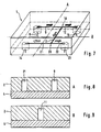
- FIGS 7 to 9 show an embodiment of a separation module in which in the flow channels leading from the inlet 8 to the plasma outlet 14 two branches 10 and 20 are arranged one behind the other in such a way that is improved by a two-stage separation process, the overall separation effect , This can be achieved in that - as shown - the outgoing from the first branch 10 plasma channel leads to another branch 20 so that it forms an inflow channel for the further branch 20 and from the further branch 20, a further plasma channel 21 and another Branch waste channel 22, wherein the plasma channel 21 leads to the plasma outlet 14 and the waste channel 22 to a second waste outlet 23.
- the dimensions of the drainage channels and the operating condition are chosen so that the liquid in the further waste channel 22 flows much faster than in the other plasma channel 21, that at the second branch 20 a separation in a liquid flow with higher particle concentration ( Waste channel 22) and in a liquid flow with lower particle concentration (plasma channel 21) takes place.
- the separation process can also be carried out in three or more stages by means of a correspondingly modified separation module.
- a suitable (not shown) separation module has a series of branches, whose respective inflow channel is formed by the plasma channel of the preceding branch, wherein at each of these branches the flow rate ratios described are met.
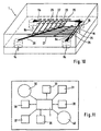
- Fig. 10 shows an embodiment of a separation module 1, in which an increased separation efficiency is achieved in that a series of branches 25 is arranged one behind the other such that in each case the waste channel of the preceding branch forms the inflow channel of the subsequent branch.
- the plasma channels 27 branching off from the branchings 25 lead into a common collecting line 28 and from there to the plasma outlet 14.
- such an arrangement is present symmetrically twice, the blood being fed through inlets 8a and 8b into the first inflow channel 9a or 9b becomes. From there it flows along a channel 26a and 26b, respectively, whose sections lying between the branches 25 each form the waste channel of the preceding branch and the inflow channel of the subsequent branch.
- the separation effect of the invention causes the concentration of erythrocytes in these channels 26a and 26b constantly increases.
- the plasma channels in the case shown in terms of their length) are dimensioned so that the flow velocity of the transported therein Fluid decreases in the direction in which increases the supplied at the respective branching erythrocyte concentration.
- FIG. 11 shows a possible conception according to which a separation module 1 is integrated planarly into an analysis chip 31 together with other modular elements required for an analysis.
- the inlet of the separation module 1 is connected to a blood reservoir 32.
- test modules 33 to 38 are connected, which can be used to determine different analytes or, for example, for more accurate analysis of different concentration ranges of the same analyte.
- a waste container 40 is integrated, into which the liquid is conducted from one or more waste outlets of the separation module 1.
Landscapes
- Health & Medical Sciences (AREA)
- Life Sciences & Earth Sciences (AREA)
- Chemical & Material Sciences (AREA)
- Engineering & Computer Science (AREA)
- Hematology (AREA)
- Biomedical Technology (AREA)
- General Health & Medical Sciences (AREA)
- Physics & Mathematics (AREA)
- Analytical Chemistry (AREA)
- Molecular Biology (AREA)
- Immunology (AREA)
- Pathology (AREA)
- Heart & Thoracic Surgery (AREA)
- General Physics & Mathematics (AREA)
- Biochemistry (AREA)
- Vascular Medicine (AREA)
- Dispersion Chemistry (AREA)
- Cardiology (AREA)
- Animal Behavior & Ethology (AREA)
- Medicinal Chemistry (AREA)
- Clinical Laboratory Science (AREA)
- Chemical Kinetics & Catalysis (AREA)
- Urology & Nephrology (AREA)
- Biophysics (AREA)
- Ecology (AREA)
- Anesthesiology (AREA)
- Food Science & Technology (AREA)
- Public Health (AREA)
- Veterinary Medicine (AREA)
- Investigating Or Analysing Biological Materials (AREA)
- Sampling And Sample Adjustment (AREA)
- Separation Of Solids By Using Liquids Or Pneumatic Power (AREA)
- Physical Or Chemical Processes And Apparatus (AREA)
- Medicines Containing Material From Animals Or Micro-Organisms (AREA)
- Solid-Sorbent Or Filter-Aiding Compositions (AREA)
Applications Claiming Priority (3)
| Application Number | Priority Date | Filing Date | Title |
|---|---|---|---|
| DE10150549 | 2001-10-12 | ||
| DE10150549A DE10150549A1 (de) | 2001-10-12 | 2001-10-12 | Verfahren und Trennmodul zum Abtrennen von Partikeln aus einer Dispersion, insbesondere von Blutkörperchen aus Blut |
| PCT/EP2002/010336 WO2003033096A2 (de) | 2001-10-12 | 2002-09-14 | Verfahren und trennmodul zum abtrennen von partikeln aus einer dispersion, insbesondere von blutkörperchen aus blut |
Publications (2)
| Publication Number | Publication Date |
|---|---|
| EP1434637A2 EP1434637A2 (de) | 2004-07-07 |
| EP1434637B1 true EP1434637B1 (de) | 2006-02-08 |
Family
ID=7702370
Family Applications (1)
| Application Number | Title | Priority Date | Filing Date |
|---|---|---|---|
| EP02774618A Expired - Lifetime EP1434637B1 (de) | 2001-10-12 | 2002-09-14 | Verfahren und trennmodul zum abtrennen von partikeln aus einer dispersion, insbesondere von blutkörperchen aus blut |
Country Status (9)
| Country | Link |
|---|---|
| US (1) | US7527740B2 (enExample) |
| EP (1) | EP1434637B1 (enExample) |
| JP (1) | JP4005022B2 (enExample) |
| AT (1) | ATE317281T1 (enExample) |
| AU (1) | AU2002340906A1 (enExample) |
| CA (1) | CA2463223C (enExample) |
| DE (2) | DE10150549A1 (enExample) |
| ES (1) | ES2257574T3 (enExample) |
| WO (1) | WO2003033096A2 (enExample) |
Families Citing this family (12)
| Publication number | Priority date | Publication date | Assignee | Title |
|---|---|---|---|---|
| DE10313201A1 (de) * | 2003-03-21 | 2004-10-07 | Steag Microparts Gmbh | Mikrostrukturierte Trennvorrichtung und mikrofluidisches Verfahren zum Abtrennen von flüssigen Bestandteilen aus einer Flüssigkeit, die Partikel enthält |
| WO2006093845A2 (en) * | 2005-02-28 | 2006-09-08 | Careside Medical Llc | A micro-fluidic fluid separation device and method |
| JP2007021465A (ja) * | 2005-07-12 | 2007-02-01 | Minoru Seki | 粒子を連続的に濃縮・分離するための流路構造および方法 |
| DE102005050167B4 (de) * | 2005-10-19 | 2009-02-19 | Advalytix Ag | Konzentrationsverfahren, Konzentrationsvorrichtung und Reaktionsverfahren |
| JP4686683B2 (ja) * | 2006-05-24 | 2011-05-25 | 国立大学法人京都大学 | 血漿分離用マイクロ流路 |
| US8685258B2 (en) * | 2008-02-27 | 2014-04-01 | Fenwal, Inc. | Systems and methods for conveying multiple blood components to a recipient |
| US8075468B2 (en) * | 2008-02-27 | 2011-12-13 | Fenwal, Inc. | Systems and methods for mid-processing calculation of blood composition |
| UY31720A1 (es) * | 2008-03-19 | 2009-09-30 | Procedimiento y aparato para separar particulas en un fluido | |
| JP2010071857A (ja) * | 2008-09-19 | 2010-04-02 | Sekisui Chem Co Ltd | 血漿分離装置 |
| US8980106B2 (en) | 2010-12-15 | 2015-03-17 | Abbott Laboratories | Apparatus and method for separation of whole blood into plasma or serum and cells |
| DE102012206371A1 (de) * | 2012-04-18 | 2013-10-24 | Siemens Ag | Durchflusssystem mit einer Rückhaltestruktur für Partikel und dessen Verwendung |
| WO2014128960A1 (ja) * | 2013-02-25 | 2014-08-28 | 株式会社メニコン | マイクロ流体デバイス |
Family Cites Families (24)
| Publication number | Priority date | Publication date | Assignee | Title |
|---|---|---|---|---|
| US3695942A (en) * | 1970-12-02 | 1972-10-03 | Amchem Prod | Zirconium rinse for phosphate coated metal surfaces |
| US3791933A (en) | 1971-02-25 | 1974-02-12 | Geomet | Rapid methods for assay of enzyme substrates and metabolites |
| US4148670A (en) * | 1976-04-05 | 1979-04-10 | Amchem Products, Inc. | Coating solution for metal surface |
| FR2417537A1 (fr) * | 1978-02-21 | 1979-09-14 | Parker Ste Continentale | Composition a base d'hafnium pour inhiber la corrosion des metaux |
| IT1111586B (it) * | 1979-03-16 | 1986-01-13 | Parker Italiana | Composizioni protettive per superfici d'acciaio e processo per la loro preparazione |
| DE3029579C2 (de) | 1980-08-05 | 1985-12-12 | Boehringer Mannheim Gmbh, 6800 Mannheim | Verfahren und Mittel zur Abtrennung von Plasma oder Serum aus Vollblut |
| EP0057907B1 (en) | 1981-02-05 | 1986-12-30 | Asahi Kasei Kogyo Kabushiki Kaisha | Apparatus for separating blood components |
| US4457790A (en) * | 1983-05-09 | 1984-07-03 | Parker Chemical Company | Treatment of metal with group IV B metal ion and derivative of polyalkenylphenol |
| US4470853A (en) * | 1983-10-03 | 1984-09-11 | Coral Chemical Company | Coating compositions and method for the treatment of metal surfaces |
| JPS60201253A (ja) | 1984-03-26 | 1985-10-11 | Jeol Ltd | 血漿採取装置 |
| US5011551A (en) * | 1988-12-22 | 1991-04-30 | The United States Of America As Represented By The Secretary Of The Army | Protective coating for steel surfaces and method of application |
| US5125989A (en) * | 1989-04-21 | 1992-06-30 | Henkel Corporation | Method and composition for coating aluminum |
| US5656070A (en) * | 1992-11-24 | 1997-08-12 | Ensci Inc. | Corrosion inhibiting compositions containing plant derived catechol complexes |
| US5380374A (en) * | 1993-10-15 | 1995-01-10 | Circle-Prosco, Inc. | Conversion coatings for metal surfaces |
| US5922210A (en) * | 1995-06-16 | 1999-07-13 | University Of Washington | Tangential flow planar microfabricated fluid filter and method of using thereof |
| US5711996A (en) * | 1995-09-28 | 1998-01-27 | Man-Gill Chemical Company | Aqueous coating compositions and coated metal surfaces |
| US5662746A (en) * | 1996-02-23 | 1997-09-02 | Brent America, Inc. | Composition and method for treatment of phosphated metal surfaces |
| JP3903098B2 (ja) | 1997-07-18 | 2007-04-11 | 富士フイルム株式会社 | 血液濾過方法 |
| EP1003759A2 (en) * | 1997-08-13 | 2000-05-31 | Cepheid | Microstructures for the manipulation of fluid samples |
| US7351376B1 (en) * | 2000-06-05 | 2008-04-01 | California Institute Of Technology | Integrated active flux microfluidic devices and methods |
| EP1309404A2 (en) * | 2000-08-07 | 2003-05-14 | Nanostream, Inc. | Fluidic mixer in microfluidic system |
| US7670559B2 (en) * | 2001-02-15 | 2010-03-02 | Caliper Life Sciences, Inc. | Microfluidic systems with enhanced detection systems |
| JP4148778B2 (ja) * | 2001-03-09 | 2008-09-10 | バイオミクロ システムズ インコーポレイティッド | アレイとのミクロ流体的インターフェース機器 |
| US20020187072A1 (en) * | 2001-06-07 | 2002-12-12 | Nanostream, Inc. | Multi-layer microfluidic splitter |
-
2001
- 2001-10-12 DE DE10150549A patent/DE10150549A1/de not_active Withdrawn
-
2002
- 2002-09-14 AT AT02774618T patent/ATE317281T1/de active
- 2002-09-14 JP JP2003535890A patent/JP4005022B2/ja not_active Expired - Fee Related
- 2002-09-14 CA CA002463223A patent/CA2463223C/en not_active Expired - Fee Related
- 2002-09-14 ES ES02774618T patent/ES2257574T3/es not_active Expired - Lifetime
- 2002-09-14 EP EP02774618A patent/EP1434637B1/de not_active Expired - Lifetime
- 2002-09-14 DE DE50205804T patent/DE50205804D1/de not_active Expired - Lifetime
- 2002-09-14 US US10/492,256 patent/US7527740B2/en not_active Expired - Fee Related
- 2002-09-14 WO PCT/EP2002/010336 patent/WO2003033096A2/de not_active Ceased
- 2002-09-14 AU AU2002340906A patent/AU2002340906A1/en not_active Abandoned
Non-Patent Citations (1)
| Title |
|---|
| PRIES A.R.; SECOMB T.W.; GAEHTGENS P.: "Biophysical aspects of blood flow in the microvasculature", CARDIOVASCULAR RESEARCH, vol. 32, 1996, ELSEVIAR, pages 654 - 667 * |
Also Published As
| Publication number | Publication date |
|---|---|
| CA2463223C (en) | 2009-08-25 |
| AU2002340906A1 (en) | 2003-04-28 |
| ES2257574T3 (es) | 2006-08-01 |
| EP1434637A2 (de) | 2004-07-07 |
| ATE317281T1 (de) | 2006-02-15 |
| CA2463223A1 (en) | 2003-04-24 |
| DE50205804D1 (de) | 2006-04-20 |
| JP4005022B2 (ja) | 2007-11-07 |
| US20050029190A1 (en) | 2005-02-10 |
| JP2005505770A (ja) | 2005-02-24 |
| WO2003033096A2 (de) | 2003-04-24 |
| US7527740B2 (en) | 2009-05-05 |
| DE10150549A1 (de) | 2003-04-17 |
| WO2003033096A3 (de) | 2003-12-18 |
Similar Documents
| Publication | Publication Date | Title |
|---|---|---|
| DE3781645T2 (de) | Blutscheidungsgeraet unter niedrigen druckverhaeltnissen. | |
| DE69303898T2 (de) | Fluessigkeitsbehandlung in mikrofabrizierten analytischen vorrichtungen | |
| DE60112414T2 (de) | Kapillarströmungssteuerung in einer medizinischen diagnosevorrichtung | |
| EP1459773B1 (de) | Mikrostrukturierte Trennvorrichtung und mikrofluidisches Verfahren zum Abtrennen von flüssigen Bestandteilen aus einer Flüssigkeit, die Partikel enthält | |
| EP1434637B1 (de) | Verfahren und trennmodul zum abtrennen von partikeln aus einer dispersion, insbesondere von blutkörperchen aus blut | |
| DE102011078961B4 (de) | System zum Separieren von Körperflüssigkeitsbestandteilen und Verfahren zum Herstellen eines derartigen Systems | |
| EP1315553B1 (de) | Vorrichtung und verfahren zur separation von ungelösten bestandteilen aus biologischen flüssigkeiten | |
| DE69623180T2 (de) | Filter zum Trennen von Plasma, Verfahren zur Plasmatrennung unter Verwendung dieses Filters und Trennungsvorrichtung für Plasma | |
| DE60108950T2 (de) | Verfahren und vorrichtung zur plasmidgewinnung mit hilfe von ultrafiltration | |
| EP1522343B1 (de) | Analytisches Testelement umfassend ein hydrophiles Netzwerk zur Bildung eines Kapillarkanals, dessen Verwendung und Verfahren zur Bestimmung eines Analyten in einer Flüssigkeit | |
| DE10334341A1 (de) | Kaskadierte hydrodynamische Fokussierung in Mikrofluidikkanälen | |
| DE112019000463T5 (de) | Mikrofluid-chips zum reinigen und fraktionieren von partikeln | |
| DE10352535A1 (de) | Mikrostrukturierte Trennvorrichtung und Verfahren zum Abtrennen von flüssigen Bestandteilen aus einer Partikel enthaltenden Flüssigkeit | |
| EP2528686A1 (de) | Anordnung und verfahren zur filtration einer flüssigkeit und verwendung in der mikroskopie | |
| EP1253977B1 (de) | Verfahren und vorrichtung zur abführung suspendierter mikropartikel aus einem fluidischen mikrosystem | |
| DE69407969T2 (de) | Vorrichtung und verfahren zur trennung von plasma aus einem blutprodukt | |
| DE2244780C3 (enExample) | ||
| WO2013072110A1 (de) | Mikrofluidisches filterelement zum abscheiden von probenbestandteilen aus einem biologischen probenfluid | |
| DE2342324C3 (de) | Verfahren und Vorrichtung zur Trennung nicht mischbarer Flüssigkeiten | |
| DE102015218177B4 (de) | Isolation und Anreicherung magnetisch markierter Zellen im Durchfluss | |
| EP2440940B1 (de) | Vorrichtung und verfahren zur erzeugung und/oder anordnung von sequenzen einer oder mehrerer fluidproben in einem trägerfluid | |
| DE19721477A1 (de) | Mikrobieller Membranreaktor zur Verwendung in Fließsystemen | |
| EP3973288B1 (de) | Mikrofluidisches analysesystem zur analyse von blutproben | |
| DE10149316A1 (de) | Mikrokrümmer für die Trennung von Suspensionen | |
| DE102012220250A1 (de) | Fluidikmodul für eine zentrifugale filtration und verfahren zum filtern einer probe |
Legal Events
| Date | Code | Title | Description |
|---|---|---|---|
| PUAI | Public reference made under article 153(3) epc to a published international application that has entered the european phase |
Free format text: ORIGINAL CODE: 0009012 |
|
| 17P | Request for examination filed |
Effective date: 20040410 |
|
| AK | Designated contracting states |
Kind code of ref document: A2 Designated state(s): AT BE BG CH CY CZ DE DK EE ES FI FR GB GR IE IT LI LU MC NL PT SE SK TR |
|
| AX | Request for extension of the european patent |
Extension state: AL LT LV MK RO SI |
|
| RIN1 | Information on inventor provided before grant (corrected) |
Inventor name: FIEDLER, WOLFGANG Inventor name: OCVIRK, GREGOR Inventor name: EFFENHAUSER, CARLO |
|
| 17Q | First examination report despatched |
Effective date: 20050217 |
|
| GRAP | Despatch of communication of intention to grant a patent |
Free format text: ORIGINAL CODE: EPIDOSNIGR1 |
|
| GRAS | Grant fee paid |
Free format text: ORIGINAL CODE: EPIDOSNIGR3 |
|
| GRAA | (expected) grant |
Free format text: ORIGINAL CODE: 0009210 |
|
| AK | Designated contracting states |
Kind code of ref document: B1 Designated state(s): AT BE BG CH CY CZ DE DK EE ES FI FR GB GR IE IT LI LU MC NL PT SE SK TR |
|
| PG25 | Lapsed in a contracting state [announced via postgrant information from national office to epo] |
Ref country code: IE Free format text: LAPSE BECAUSE OF FAILURE TO SUBMIT A TRANSLATION OF THE DESCRIPTION OR TO PAY THE FEE WITHIN THE PRESCRIBED TIME-LIMIT Effective date: 20060208 Ref country code: FI Free format text: LAPSE BECAUSE OF FAILURE TO SUBMIT A TRANSLATION OF THE DESCRIPTION OR TO PAY THE FEE WITHIN THE PRESCRIBED TIME-LIMIT Effective date: 20060208 Ref country code: NL Free format text: LAPSE BECAUSE OF FAILURE TO SUBMIT A TRANSLATION OF THE DESCRIPTION OR TO PAY THE FEE WITHIN THE PRESCRIBED TIME-LIMIT Effective date: 20060208 Ref country code: SK Free format text: LAPSE BECAUSE OF FAILURE TO SUBMIT A TRANSLATION OF THE DESCRIPTION OR TO PAY THE FEE WITHIN THE PRESCRIBED TIME-LIMIT Effective date: 20060208 |
|
| REG | Reference to a national code |
Ref country code: GB Ref legal event code: FG4D Free format text: NOT ENGLISH |
|
| REG | Reference to a national code |
Ref country code: CH Ref legal event code: EP |
|
| REG | Reference to a national code |
Ref country code: IE Ref legal event code: FG4D Free format text: LANGUAGE OF EP DOCUMENT: GERMAN |
|
| REG | Reference to a national code |
Ref country code: CH Ref legal event code: NV Representative=s name: A. BRAUN, BRAUN, HERITIER, ESCHMANN AG PATENTANWAE |
|
| REF | Corresponds to: |
Ref document number: 50205804 Country of ref document: DE Date of ref document: 20060420 Kind code of ref document: P |
|
| PG25 | Lapsed in a contracting state [announced via postgrant information from national office to epo] |
Ref country code: BG Free format text: LAPSE BECAUSE OF FAILURE TO SUBMIT A TRANSLATION OF THE DESCRIPTION OR TO PAY THE FEE WITHIN THE PRESCRIBED TIME-LIMIT Effective date: 20060508 Ref country code: SE Free format text: LAPSE BECAUSE OF FAILURE TO SUBMIT A TRANSLATION OF THE DESCRIPTION OR TO PAY THE FEE WITHIN THE PRESCRIBED TIME-LIMIT Effective date: 20060508 Ref country code: DK Free format text: LAPSE BECAUSE OF FAILURE TO SUBMIT A TRANSLATION OF THE DESCRIPTION OR TO PAY THE FEE WITHIN THE PRESCRIBED TIME-LIMIT Effective date: 20060508 |
|
| GBT | Gb: translation of ep patent filed (gb section 77(6)(a)/1977) |
Effective date: 20060424 |
|
| NLV1 | Nl: lapsed or annulled due to failure to fulfill the requirements of art. 29p and 29m of the patents act | ||
| PG25 | Lapsed in a contracting state [announced via postgrant information from national office to epo] |
Ref country code: PT Free format text: LAPSE BECAUSE OF FAILURE TO SUBMIT A TRANSLATION OF THE DESCRIPTION OR TO PAY THE FEE WITHIN THE PRESCRIBED TIME-LIMIT Effective date: 20060710 |
|
| REG | Reference to a national code |
Ref country code: ES Ref legal event code: FG2A Ref document number: 2257574 Country of ref document: ES Kind code of ref document: T3 |
|
| REG | Reference to a national code |
Ref country code: IE Ref legal event code: FD4D |
|
| ET | Fr: translation filed | ||
| PG25 | Lapsed in a contracting state [announced via postgrant information from national office to epo] |
Ref country code: MC Free format text: LAPSE BECAUSE OF NON-PAYMENT OF DUE FEES Effective date: 20060930 Ref country code: BE Free format text: LAPSE BECAUSE OF NON-PAYMENT OF DUE FEES Effective date: 20060930 |
|
| PLBE | No opposition filed within time limit |
Free format text: ORIGINAL CODE: 0009261 |
|
| STAA | Information on the status of an ep patent application or granted ep patent |
Free format text: STATUS: NO OPPOSITION FILED WITHIN TIME LIMIT |
|
| 26N | No opposition filed |
Effective date: 20061109 |
|
| BERE | Be: lapsed |
Owner name: ROCHE DIAGNOSTICS G.M.B.H. Effective date: 20060930 Owner name: F. HOFFMANN-LA ROCHE A.G. Effective date: 20060930 |
|
| PG25 | Lapsed in a contracting state [announced via postgrant information from national office to epo] |
Ref country code: GR Free format text: LAPSE BECAUSE OF FAILURE TO SUBMIT A TRANSLATION OF THE DESCRIPTION OR TO PAY THE FEE WITHIN THE PRESCRIBED TIME-LIMIT Effective date: 20060509 Ref country code: CZ Free format text: LAPSE BECAUSE OF FAILURE TO SUBMIT A TRANSLATION OF THE DESCRIPTION OR TO PAY THE FEE WITHIN THE PRESCRIBED TIME-LIMIT Effective date: 20060208 |
|
| REG | Reference to a national code |
Ref country code: CH Ref legal event code: PFA Owner name: F. HOFFMANN-LA ROCHE AG Free format text: F. HOFFMANN-LA ROCHE AG#GRENZACHERSTRASSE 124#4070 BASEL (CH) -TRANSFER TO- F. HOFFMANN-LA ROCHE AG#GRENZACHERSTRASSE 124#4070 BASEL (CH) |
|
| PG25 | Lapsed in a contracting state [announced via postgrant information from national office to epo] |
Ref country code: EE Free format text: LAPSE BECAUSE OF FAILURE TO SUBMIT A TRANSLATION OF THE DESCRIPTION OR TO PAY THE FEE WITHIN THE PRESCRIBED TIME-LIMIT Effective date: 20060208 |
|
| PG25 | Lapsed in a contracting state [announced via postgrant information from national office to epo] |
Ref country code: TR Free format text: LAPSE BECAUSE OF FAILURE TO SUBMIT A TRANSLATION OF THE DESCRIPTION OR TO PAY THE FEE WITHIN THE PRESCRIBED TIME-LIMIT Effective date: 20060208 Ref country code: LU Free format text: LAPSE BECAUSE OF NON-PAYMENT OF DUE FEES Effective date: 20060914 |
|
| PG25 | Lapsed in a contracting state [announced via postgrant information from national office to epo] |
Ref country code: CY Free format text: LAPSE BECAUSE OF FAILURE TO SUBMIT A TRANSLATION OF THE DESCRIPTION OR TO PAY THE FEE WITHIN THE PRESCRIBED TIME-LIMIT Effective date: 20060208 |
|
| REG | Reference to a national code |
Ref country code: CH Ref legal event code: PCAR Free format text: NEW ADDRESS: HOLBEINSTRASSE 36-38, 4051 BASEL (CH) |
|
| REG | Reference to a national code |
Ref country code: DE Ref legal event code: R081 Ref document number: 50205804 Country of ref document: DE Owner name: ROCHE DIABETES CARE GMBH, DE Free format text: FORMER OWNER: ROCHE DIAGNOSTICS GMBH, 68305 MANNHEIM, DE |
|
| REG | Reference to a national code |
Ref country code: FR Ref legal event code: PLFP Year of fee payment: 15 |
|
| PGFP | Annual fee paid to national office [announced via postgrant information from national office to epo] |
Ref country code: GB Payment date: 20160830 Year of fee payment: 15 Ref country code: CH Payment date: 20160725 Year of fee payment: 15 Ref country code: IT Payment date: 20160914 Year of fee payment: 15 |
|
| PGFP | Annual fee paid to national office [announced via postgrant information from national office to epo] |
Ref country code: AT Payment date: 20160826 Year of fee payment: 15 Ref country code: FR Payment date: 20160817 Year of fee payment: 15 |
|
| PGFP | Annual fee paid to national office [announced via postgrant information from national office to epo] |
Ref country code: ES Payment date: 20160907 Year of fee payment: 15 |
|
| PGFP | Annual fee paid to national office [announced via postgrant information from national office to epo] |
Ref country code: DE Payment date: 20160928 Year of fee payment: 15 |
|
| REG | Reference to a national code |
Ref country code: DE Ref legal event code: R119 Ref document number: 50205804 Country of ref document: DE |
|
| REG | Reference to a national code |
Ref country code: CH Ref legal event code: PL |
|
| REG | Reference to a national code |
Ref country code: AT Ref legal event code: MM01 Ref document number: 317281 Country of ref document: AT Kind code of ref document: T Effective date: 20170914 |
|
| GBPC | Gb: european patent ceased through non-payment of renewal fee |
Effective date: 20170914 |
|
| REG | Reference to a national code |
Ref country code: FR Ref legal event code: ST Effective date: 20180531 |
|
| PG25 | Lapsed in a contracting state [announced via postgrant information from national office to epo] |
Ref country code: CH Free format text: LAPSE BECAUSE OF NON-PAYMENT OF DUE FEES Effective date: 20170930 Ref country code: GB Free format text: LAPSE BECAUSE OF NON-PAYMENT OF DUE FEES Effective date: 20170914 Ref country code: LI Free format text: LAPSE BECAUSE OF NON-PAYMENT OF DUE FEES Effective date: 20170930 Ref country code: DE Free format text: LAPSE BECAUSE OF NON-PAYMENT OF DUE FEES Effective date: 20180404 |
|
| PG25 | Lapsed in a contracting state [announced via postgrant information from national office to epo] |
Ref country code: IT Free format text: LAPSE BECAUSE OF NON-PAYMENT OF DUE FEES Effective date: 20170914 Ref country code: FR Free format text: LAPSE BECAUSE OF NON-PAYMENT OF DUE FEES Effective date: 20171002 Ref country code: AT Free format text: LAPSE BECAUSE OF NON-PAYMENT OF DUE FEES Effective date: 20170914 |
|
| REG | Reference to a national code |
Ref country code: ES Ref legal event code: FD2A Effective date: 20181019 |
|
| PG25 | Lapsed in a contracting state [announced via postgrant information from national office to epo] |
Ref country code: ES Free format text: LAPSE BECAUSE OF NON-PAYMENT OF DUE FEES Effective date: 20170915 |