EP1434637B1 - Method and separating module for the separation of particles from a dispersion, in particular of blood corpuscles from blood - Google Patents
Method and separating module for the separation of particles from a dispersion, in particular of blood corpuscles from blood Download PDFInfo
- Publication number
- EP1434637B1 EP1434637B1 EP02774618A EP02774618A EP1434637B1 EP 1434637 B1 EP1434637 B1 EP 1434637B1 EP 02774618 A EP02774618 A EP 02774618A EP 02774618 A EP02774618 A EP 02774618A EP 1434637 B1 EP1434637 B1 EP 1434637B1
- Authority
- EP
- European Patent Office
- Prior art keywords
- drain channel
- channel
- junction
- separating
- flow
- Prior art date
- Legal status (The legal status is an assumption and is not a legal conclusion. Google has not performed a legal analysis and makes no representation as to the accuracy of the status listed.)
- Expired - Lifetime
Links
- 239000002245 particle Substances 0.000 title claims abstract description 51
- 238000000034 method Methods 0.000 title claims abstract description 24
- 210000004369 blood Anatomy 0.000 title claims abstract description 22
- 239000008280 blood Substances 0.000 title claims abstract description 22
- 239000006185 dispersion Substances 0.000 title claims abstract description 20
- 238000000926 separation method Methods 0.000 title description 57
- 210000000601 blood cell Anatomy 0.000 title description 8
- 239000012530 fluid Substances 0.000 claims abstract description 25
- 239000000758 substrate Substances 0.000 claims abstract description 11
- 239000012472 biological sample Substances 0.000 claims abstract description 4
- 210000002381 plasma Anatomy 0.000 description 54
- 239000007788 liquid Substances 0.000 description 23
- 239000002699 waste material Substances 0.000 description 21
- 238000004458 analytical method Methods 0.000 description 15
- 230000000694 effects Effects 0.000 description 14
- 210000003743 erythrocyte Anatomy 0.000 description 14
- 238000004519 manufacturing process Methods 0.000 description 12
- 238000012360 testing method Methods 0.000 description 9
- 239000000463 material Substances 0.000 description 7
- 230000010354 integration Effects 0.000 description 6
- 230000008859 change Effects 0.000 description 5
- 238000000605 extraction Methods 0.000 description 5
- 238000001914 filtration Methods 0.000 description 5
- 239000011148 porous material Substances 0.000 description 5
- 230000004888 barrier function Effects 0.000 description 4
- 230000001413 cellular effect Effects 0.000 description 3
- 239000003153 chemical reaction reagent Substances 0.000 description 3
- 238000005530 etching Methods 0.000 description 3
- 238000005191 phase separation Methods 0.000 description 3
- 230000008569 process Effects 0.000 description 3
- 239000000523 sample Substances 0.000 description 3
- 230000008901 benefit Effects 0.000 description 2
- 230000017531 blood circulation Effects 0.000 description 2
- 238000009534 blood test Methods 0.000 description 2
- 230000007423 decrease Effects 0.000 description 2
- 238000007599 discharging Methods 0.000 description 2
- 239000000706 filtrate Substances 0.000 description 2
- 239000003365 glass fiber Substances 0.000 description 2
- 238000002955 isolation Methods 0.000 description 2
- 238000000608 laser ablation Methods 0.000 description 2
- 239000012528 membrane Substances 0.000 description 2
- 239000000047 product Substances 0.000 description 2
- 238000005086 pumping Methods 0.000 description 2
- 238000011084 recovery Methods 0.000 description 2
- 238000012552 review Methods 0.000 description 2
- 241001136792 Alle Species 0.000 description 1
- 206010018910 Haemolysis Diseases 0.000 description 1
- XUIMIQQOPSSXEZ-UHFFFAOYSA-N Silicon Chemical compound [Si] XUIMIQQOPSSXEZ-UHFFFAOYSA-N 0.000 description 1
- 238000009825 accumulation Methods 0.000 description 1
- 239000012491 analyte Substances 0.000 description 1
- QVGXLLKOCUKJST-UHFFFAOYSA-N atomic oxygen Chemical compound [O] QVGXLLKOCUKJST-UHFFFAOYSA-N 0.000 description 1
- TZCXTZWJZNENPQ-UHFFFAOYSA-L barium sulfate Chemical compound [Ba+2].[O-]S([O-])(=O)=O TZCXTZWJZNENPQ-UHFFFAOYSA-L 0.000 description 1
- 239000011324 bead Substances 0.000 description 1
- 239000013060 biological fluid Substances 0.000 description 1
- 238000011138 biotechnological process Methods 0.000 description 1
- 230000000903 blocking effect Effects 0.000 description 1
- 238000004820 blood count Methods 0.000 description 1
- 238000004113 cell culture Methods 0.000 description 1
- 238000005119 centrifugation Methods 0.000 description 1
- 238000003889 chemical engineering Methods 0.000 description 1
- 239000012141 concentrate Substances 0.000 description 1
- 239000000470 constituent Substances 0.000 description 1
- 230000008878 coupling Effects 0.000 description 1
- 238000010168 coupling process Methods 0.000 description 1
- 238000005859 coupling reaction Methods 0.000 description 1
- 230000002526 effect on cardiovascular system Effects 0.000 description 1
- 238000011156 evaluation Methods 0.000 description 1
- 238000002474 experimental method Methods 0.000 description 1
- 239000002657 fibrous material Substances 0.000 description 1
- 238000005534 hematocrit Methods 0.000 description 1
- 230000008588 hemolysis Effects 0.000 description 1
- 238000000338 in vitro Methods 0.000 description 1
- 238000001727 in vivo Methods 0.000 description 1
- 238000001746 injection moulding Methods 0.000 description 1
- 238000011835 investigation Methods 0.000 description 1
- 238000005259 measurement Methods 0.000 description 1
- 238000001471 micro-filtration Methods 0.000 description 1
- 229910052760 oxygen Inorganic materials 0.000 description 1
- 239000001301 oxygen Substances 0.000 description 1
- 230000037361 pathway Effects 0.000 description 1
- 230000000704 physical effect Effects 0.000 description 1
- 238000003825 pressing Methods 0.000 description 1
- 102000004169 proteins and genes Human genes 0.000 description 1
- 108090000623 proteins and genes Proteins 0.000 description 1
- 238000000746 purification Methods 0.000 description 1
- 238000011160 research Methods 0.000 description 1
- 230000000717 retained effect Effects 0.000 description 1
- 230000033764 rhythmic process Effects 0.000 description 1
- 229910052710 silicon Inorganic materials 0.000 description 1
- 239000010703 silicon Substances 0.000 description 1
- 210000003462 vein Anatomy 0.000 description 1
- 238000004065 wastewater treatment Methods 0.000 description 1
Images

Classifications
-
- G—PHYSICS
- G01—MEASURING; TESTING
- G01N—INVESTIGATING OR ANALYSING MATERIALS BY DETERMINING THEIR CHEMICAL OR PHYSICAL PROPERTIES
- G01N15/00—Investigating characteristics of particles; Investigating permeability, pore-volume, or surface-area of porous materials
- G01N15/04—Investigating sedimentation of particle suspensions
- G01N15/05—Investigating sedimentation of particle suspensions in blood
-
- A—HUMAN NECESSITIES
- A61—MEDICAL OR VETERINARY SCIENCE; HYGIENE
- A61M—DEVICES FOR INTRODUCING MEDIA INTO, OR ONTO, THE BODY; DEVICES FOR TRANSDUCING BODY MEDIA OR FOR TAKING MEDIA FROM THE BODY; DEVICES FOR PRODUCING OR ENDING SLEEP OR STUPOR
- A61M1/00—Suction or pumping devices for medical purposes; Devices for carrying-off, for treatment of, or for carrying-over, body-liquids; Drainage systems
- A61M1/36—Other treatment of blood in a by-pass of the natural circulatory system, e.g. temperature adaptation, irradiation ; Extra-corporeal blood circuits
- A61M1/3693—Other treatment of blood in a by-pass of the natural circulatory system, e.g. temperature adaptation, irradiation ; Extra-corporeal blood circuits using separation based on different densities of components, e.g. centrifuging
-
- B—PERFORMING OPERATIONS; TRANSPORTING
- B01—PHYSICAL OR CHEMICAL PROCESSES OR APPARATUS IN GENERAL
- B01L—CHEMICAL OR PHYSICAL LABORATORY APPARATUS FOR GENERAL USE
- B01L3/00—Containers or dishes for laboratory use, e.g. laboratory glassware; Droppers
- B01L3/50—Containers for the purpose of retaining a material to be analysed, e.g. test tubes
- B01L3/502—Containers for the purpose of retaining a material to be analysed, e.g. test tubes with fluid transport, e.g. in multi-compartment structures
- B01L3/5027—Containers for the purpose of retaining a material to be analysed, e.g. test tubes with fluid transport, e.g. in multi-compartment structures by integrated microfluidic structures, i.e. dimensions of channels and chambers are such that surface tension forces are important, e.g. lab-on-a-chip
- B01L3/502753—Containers for the purpose of retaining a material to be analysed, e.g. test tubes with fluid transport, e.g. in multi-compartment structures by integrated microfluidic structures, i.e. dimensions of channels and chambers are such that surface tension forces are important, e.g. lab-on-a-chip characterised by bulk separation arrangements on lab-on-a-chip devices, e.g. for filtration or centrifugation
-
- G—PHYSICS
- G01—MEASURING; TESTING
- G01N—INVESTIGATING OR ANALYSING MATERIALS BY DETERMINING THEIR CHEMICAL OR PHYSICAL PROPERTIES
- G01N33/00—Investigating or analysing materials by specific methods not covered by groups G01N1/00 - G01N31/00
- G01N33/48—Biological material, e.g. blood, urine; Haemocytometers
- G01N33/483—Physical analysis of biological material
- G01N33/487—Physical analysis of biological material of liquid biological material
- G01N33/49—Blood
- G01N33/491—Blood by separating the blood components
-
- B—PERFORMING OPERATIONS; TRANSPORTING
- B01—PHYSICAL OR CHEMICAL PROCESSES OR APPARATUS IN GENERAL
- B01L—CHEMICAL OR PHYSICAL LABORATORY APPARATUS FOR GENERAL USE
- B01L2200/00—Solutions for specific problems relating to chemical or physical laboratory apparatus
- B01L2200/06—Fluid handling related problems
- B01L2200/0647—Handling flowable solids, e.g. microscopic beads, cells, particles
-
- B—PERFORMING OPERATIONS; TRANSPORTING
- B01—PHYSICAL OR CHEMICAL PROCESSES OR APPARATUS IN GENERAL
- B01L—CHEMICAL OR PHYSICAL LABORATORY APPARATUS FOR GENERAL USE
- B01L2300/00—Additional constructional details
- B01L2300/08—Geometry, shape and general structure
- B01L2300/0809—Geometry, shape and general structure rectangular shaped
- B01L2300/0816—Cards, e.g. flat sample carriers usually with flow in two horizontal directions
-
- G—PHYSICS
- G01—MEASURING; TESTING
- G01N—INVESTIGATING OR ANALYSING MATERIALS BY DETERMINING THEIR CHEMICAL OR PHYSICAL PROPERTIES
- G01N15/00—Investigating characteristics of particles; Investigating permeability, pore-volume, or surface-area of porous materials
- G01N15/04—Investigating sedimentation of particle suspensions
- G01N15/05—Investigating sedimentation of particle suspensions in blood
- G01N2015/055—Investigating sedimentation of particle suspensions in blood for hematocrite determination
-
- G—PHYSICS
- G01—MEASURING; TESTING
- G01N—INVESTIGATING OR ANALYSING MATERIALS BY DETERMINING THEIR CHEMICAL OR PHYSICAL PROPERTIES
- G01N15/00—Investigating characteristics of particles; Investigating permeability, pore-volume, or surface-area of porous materials
- G01N15/10—Investigating individual particles
- G01N15/14—Electro-optical investigation, e.g. flow cytometers
- G01N2015/1486—Counting the particles
-
- Y—GENERAL TAGGING OF NEW TECHNOLOGICAL DEVELOPMENTS; GENERAL TAGGING OF CROSS-SECTIONAL TECHNOLOGIES SPANNING OVER SEVERAL SECTIONS OF THE IPC; TECHNICAL SUBJECTS COVERED BY FORMER USPC CROSS-REFERENCE ART COLLECTIONS [XRACs] AND DIGESTS
- Y10—TECHNICAL SUBJECTS COVERED BY FORMER USPC
- Y10T—TECHNICAL SUBJECTS COVERED BY FORMER US CLASSIFICATION
- Y10T436/00—Chemistry: analytical and immunological testing
- Y10T436/25—Chemistry: analytical and immunological testing including sample preparation
- Y10T436/25375—Liberation or purification of sample or separation of material from a sample [e.g., filtering, centrifuging, etc.]
Definitions
- the invention relates to a method for separating particles from a dispersion and a component for carrying out such a method. Since such a component can be used modularly as part of different systems, it is referred to here as a separation module.
- the invention can be used in particular for separating corpuscular components from biological samples, especially from blood.
- the problem arises of partially or completely removing the particles from a dispersion which contains particles dispersed in a carrier medium.
- a particularly important area is analytical methods for determining the concentration of constituents in the blood.
- blood tests can not be performed on whole blood containing the corpuscular components (blood cells). Rather, it is necessary to previously obtain from the whole blood plasma, which is as free as possible of cellular material.
- the invention is also suitable for the treatment of other dispersions, wherein the carrier medium can be not only liquid but also gaseous.
- the invention can also be used in other fields of chemical engineering and the food industry to separate particles from process streams. Further uses are in biotechnological processes (removal and isolation of cell cultures from corresponding dispersions) as well as in the field of wastewater treatment. Without restriction of generality, reference will be made below to the treatment of dispersions in liquids, mainly to the separation of plasma from whole blood.
- centrifugation techniques have been used to obtain plasma for blood tests by separating the cellular components.
- they are not suitable for modern miniaturized tests. This is especially true for the so-called near-patient diagnostics, in which a small and compact analysis element (for example in the form of a test strip) contains all necessary reagents and other means for the performance of the test, so that only the sample liquid are brought into contact with the analysis element in order to be able to change after a short time by means of a change that can be physically detected on the analysis element (in particular a color change or a change in an electrical measured variable). to determine the desired analytical result visually or with the aid of an evaluation device.
- a small and compact analysis element for example in the form of a test strip
- microchannels are produced by etching in a silicon substrate.
- the separation of the blood cells takes place in a so-called barrier channel (barrier channel) whose depth is less than 0.1 ⁇ m, so that the blood cells can not flow through the barrier channel.
- barrier channel barrier channel
- the required inflow channels and the blocking channel are produced in two consecutive production steps.
- the required, extremely small depth of the barrier channel of less than 0.1 microns is determined by the duration of the etching process in an etching bath. In view of the required high reproducibility of this manufacturing process is very difficult and expensive.
- the object of the invention is to make possible the separation of particles from a dispersion while avoiding the disadvantages described above with a separation module which can be produced simply and inexpensively.
- the separation module should preferably be a so-called "disposable" intended for single use and be suitable in particular for the generation of small amounts of plasma (less than 10 .mu.l , in particular less than 5 .mu.l ) for miniaturized tests.
- the object is achieved by a method for separating particles from a fluid dispersion, in particular for separating corpuscular components from biological samples, especially blood, by means of a separation module with a substrate having flow channels in the form of groove-shaped depressions in a surface of the substrate, comprising an inflow channel for supplying the dispersion to a branch, a first effluent channel for discharging reduced particle concentration fluid away from the branch, and a second effluent channel for discharging increased particle concentration fluid away from the branch, the fluid in the second effluent channel being so much flows faster than in the first spillway, that the dispersed particles at the branch due to the different flow rate preferably continue to flow in the second spillway.
- the filtration methods hitherto used for the purposes of the invention are based on steric selection, ie on the fact that the particles to be separated are retained because the pores of the filter medium are smaller than the diameter of the particles.
- the pore diameter of the filter medium in particular because of the easy deformability of the erythrocytes may be at most about 1 ⁇ m .
- selection is based on a completely different principle: different local particle flow velocities in different flow paths of the liquid flow in the separation module result in shear stresses which cause the particles at the branch to preferentially continue to flow into the second flow channel at the higher flow rate.
- the first drain channel with the lower flow rate contains a reduced particle concentration.
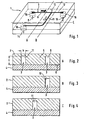
- the separation module 1 shown in Figures 1 to 4 consists essentially of a channel part 2 with flow channels 3 and a cover part 4.
- the flow channels 3 in Form of microscopic groove-shaped depressions in a surface 6 of the substrate 5 is generated.
- the channels are shown in the figures, especially in Figures 2 and 4 in greatly exaggerated size.
- Their width b is typically less than 150 .mu.m, with channel widths of less than 100 .mu.m , preferably less than 50 .mu.m , having proved particularly suitable for plasma recovery.
- the preferred dimensions are so far beyond the wavelength range of visible light that the required structures in the surface 6 of the substrate 5 can be readily produced by photolithographic techniques as described in US Pat the production of electronic chips are known.
- the width b of the channels is at least about 5 microns.
- an inlet 8 is whole blood (or other dispersion to be separated from the particles) fed into the separation module 1 and fed via an inlet channel 9 of a branch 10, at which the liquid flow into a first effluent channel 11 and into a second effluent 12th branched.
- the liquid flowing in the discharge channels 11 and 12 is removed from the separation module 1 via outlets 14 and 15, respectively.
- the inlets and outlets are formed in the case shown by existing in the cover part 4 boreholes 16 to which suitable lines, such as plastic hoses can be connected.
- the liquid in the second outflow channel 12 flows much faster than in the first outflow channel 11, that at the branching 10 the dispersed particles preferably continue to flow in the second outflow channel due to the different flow rate.
- the depths t of the channels 9, 11, 12 are greater than the width b at least in the channel sections immediately adjacent to the branching 10.
- Particularly preferred is an embodiment in which the depths are at least the inflow channel 9 and the plasma channel 11 in the immediately adjacent to the branch 10 channel section are the same size. This is especially preferred for all channels 9, 11, 12 connected to the branch
- the smallest cross-sectional dimension of the plasma channel is at least 5 ⁇ m and at most 150 ⁇ m , with values smaller than 100 ⁇ m , in particular smaller than 50 ⁇ m , being particularly preferred.
- the flow resistance of the plasma channel 11 should generally be higher than the flow resistance of the waste channel 12. This is preferably at least partially effected by the plasma channel being longer than the waste channel. This is advantageous because the flow resistance of the discharge channels 11, 12 can be adjusted more easily and precisely by a corresponding adjustment of their length than by means of a corresponding dimensioning of the cross section.
- the depth t of the discharge channels 11, 12 is the same over at least part of their length, preferably over their entire length.
- the depth of the inflow channel 9 also coincides with the (same) depth of the discharge channels 11, 12.
- the flow channels 3 are preferably the same width over almost their entire length, but it has proved to be advantageous if at least the inflow channel 9 and the waste channel 12 in the region of the inlet 8 and the outlet 15 are designed so that sharp corners, could be damaged by the erythrocytes avoided.
- Fig. 1 an oblique course of the walls of said channels 9 and 12 is indicated in this area.
- Fig. 6 is a graph of experimental data illustrating the dependence of the separation effect on the relation of the flow velocity in the drainage channels. They were obtained with a separation module according to Fig. 1, wherein the inflow channel 9 and the waste channel 12 were each 32 microns wide and 32 microns deep. The plasma channel 11 was 16 ⁇ m wide and 32 ⁇ m deep. The flow per unit time in the inflow channel 9 ranged between 0.01 and 0.5 ⁇ l / min. On the abscissa, the relation of the flow velocity v P in the plasma channel 11 to the flow velocity v F in the feed channel (F) is plotted. The ordinate shows the corresponding relation of the particle numbers N P to N F.
- the experiments were diluted at a ratio of 1: 5 Blood performed to make the erythrocytes more visible.
- the velocities v P and v F were derived from the video observation of the erythrocytes flowing in the central current path.
- the particle counts were also determined from the video data.
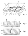
- FIGS 7 to 9 show an embodiment of a separation module in which in the flow channels leading from the inlet 8 to the plasma outlet 14 two branches 10 and 20 are arranged one behind the other in such a way that is improved by a two-stage separation process, the overall separation effect , This can be achieved in that - as shown - the outgoing from the first branch 10 plasma channel leads to another branch 20 so that it forms an inflow channel for the further branch 20 and from the further branch 20, a further plasma channel 21 and another Branch waste channel 22, wherein the plasma channel 21 leads to the plasma outlet 14 and the waste channel 22 to a second waste outlet 23.
- the dimensions of the drainage channels and the operating condition are chosen so that the liquid in the further waste channel 22 flows much faster than in the other plasma channel 21, that at the second branch 20 a separation in a liquid flow with higher particle concentration ( Waste channel 22) and in a liquid flow with lower particle concentration (plasma channel 21) takes place.
- the separation process can also be carried out in three or more stages by means of a correspondingly modified separation module.
- a suitable (not shown) separation module has a series of branches, whose respective inflow channel is formed by the plasma channel of the preceding branch, wherein at each of these branches the flow rate ratios described are met.
- Fig. 10 shows an embodiment of a separation module 1, in which an increased separation efficiency is achieved in that a series of branches 25 is arranged one behind the other such that in each case the waste channel of the preceding branch forms the inflow channel of the subsequent branch.
- the plasma channels 27 branching off from the branchings 25 lead into a common collecting line 28 and from there to the plasma outlet 14.
- such an arrangement is present symmetrically twice, the blood being fed through inlets 8a and 8b into the first inflow channel 9a or 9b becomes. From there it flows along a channel 26a and 26b, respectively, whose sections lying between the branches 25 each form the waste channel of the preceding branch and the inflow channel of the subsequent branch.
- the separation effect of the invention causes the concentration of erythrocytes in these channels 26a and 26b constantly increases.
- the plasma channels in the case shown in terms of their length) are dimensioned so that the flow velocity of the transported therein Fluid decreases in the direction in which increases the supplied at the respective branching erythrocyte concentration.
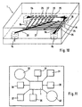
- FIG. 11 shows a possible conception according to which a separation module 1 is integrated planarly into an analysis chip 31 together with other modular elements required for an analysis.
- the inlet of the separation module 1 is connected to a blood reservoir 32.
- test modules 33 to 38 are connected, which can be used to determine different analytes or, for example, for more accurate analysis of different concentration ranges of the same analyte.
- a waste container 40 is integrated, into which the liquid is conducted from one or more waste outlets of the separation module 1.
Abstract
Description
Die Erfindung betrifft ein Verfahren zum Abtrennen von Partikeln aus einer Dispersion und ein Bauteil zur Durchführung eines solchen Verfahrens. Da ein solches Bauteil modular als Bestandteil unterschiedlicher Systeme verwendet werden kann, wird es hier als Trennmodul bezeichnet. Die Erfindung kann insbesondere zum Abtrennen von korpuskulären Bestandteilen aus biologischen Proben, vor allem aus Blut verwendet werden.The invention relates to a method for separating particles from a dispersion and a component for carrying out such a method. Since such a component can be used modularly as part of different systems, it is referred to here as a separation module. The invention can be used in particular for separating corpuscular components from biological samples, especially from blood.
Auf verschiedenen Anwendungsgebieten stellt sich das Problem, aus einer Dispersion, die in einem Trägermedium dispergierte Partikel enthält, die Partikel teilweise oder vollständig zu entfernen. Ein besonders wichtiges Gebiet sind analytische Verfahren zur Bestimmung der Konzentration von Bestandteilen im Blut. Solche Bluttests können in vielen Fällen nicht mit Vollblut durchgeführt werden, das die korpuskulären Bestandteile (Blutkörperchen) enthält. Vielmehr ist es notwendig, zuvor aus dem Vollblut Plasma zu gewinnen, das möglichst frei von zellulärem Material ist.In various fields of application, the problem arises of partially or completely removing the particles from a dispersion which contains particles dispersed in a carrier medium. A particularly important area is analytical methods for determining the concentration of constituents in the blood. In many cases, such blood tests can not be performed on whole blood containing the corpuscular components (blood cells). Rather, it is necessary to previously obtain from the whole blood plasma, which is as free as possible of cellular material.
Die Erfindung eignet sich jedoch auch zur Behandlung anderer Dispersionen, wobei das Trägermedium nicht nur flüssig, sondern auch gasförmig sein kann. Ein Beispiel für die Anwendung der Erfindung im Rahmen diagnostischanalytischer Verfahren, bei dem eine nichtbiologische Flüssigkeit behandelt wird, ist die Manipulation, Anreicherung oder Isolation von sogenannten beads, die aufgrund ihrer großen erneuerbaren Oberfläche in jüngerer Zeit beispielsweise in der kombinatorischen Chemie und der Molekularbiologie verstärkt verwendet werden. Darüber hinaus kann die Erfindung auch auf anderen Gebieten der chemischen Verfahrenstechnik und der Lebensmittelindustrie zum Einsatz kommen, um Partikel aus Prozeßströmen zu separieren. Weitere Nutzungsmöglichkeiten bestehen bei biotechnologischen Verfahren (Entfernung und Isolierung von Zellkulturen aus entsprechenden Dispersionen) sowie auf dem Gebiet der Abwasserreinigung. Ohne Beschränkung der Allgemeinheit wird nachfolgend auf die Behandlung von Dispersionen in Flüssigkeiten, hauptsächlich auf die Abtrennung von Plasma aus Vollblut, Bezug genommen.However, the invention is also suitable for the treatment of other dispersions, wherein the carrier medium can be not only liquid but also gaseous. An example of the application of the invention in the context of diagnostic analytical methods, in which a non-biological fluid is treated, is the manipulation, accumulation or isolation of so-called beads, which due to their large renewable surface has recently been increasingly used, for example, in combinatorial chemistry and molecular biology become. In addition, the invention can also be used in other fields of chemical engineering and the food industry to separate particles from process streams. Further uses are in biotechnological processes (removal and isolation of cell cultures from corresponding dispersions) as well as in the field of wastewater treatment. Without restriction of generality, reference will be made below to the treatment of dispersions in liquids, mainly to the separation of plasma from whole blood.
Traditionell wurden Zentrifugationsverfahren eingesetzt, um durch Abtrennen der zellulären Bestandteile Plasma für Bluttests zu gewinnen. Sie eignen sich jedoch nicht für moderne miniaturisierte Tests. Dies gilt insbesondere für die sogenannte patientennahe Diagnostik, bei der ein möglichst kleines und kompaktes Analyseelement (beispielsweise in Form eines Teststreifens) alle für die Durchführung des Tests notwendigen Reagenzien und sonstigen Mittel enthält, so daß nur noch die Probenflüssigkeit in Kontakt mit dem Analyseelement gebracht werden muß, um nach kurzer Zeit anhand einer physikalisch an dem Analyseelement nachweisbaren Veränderung (insbesondere einer Farbänderung oder einer Änderung einer elektrischen Meßgröße) das gewünschte analytische Resultat visuell oder mit Hilfe eines Auswertegerätes zu bestimmen.Traditionally, centrifugation techniques have been used to obtain plasma for blood tests by separating the cellular components. However, they are not suitable for modern miniaturized tests. This is especially true for the so-called near-patient diagnostics, in which a small and compact analysis element (for example in the form of a test strip) contains all necessary reagents and other means for the performance of the test, so that only the sample liquid are brought into contact with the analysis element in order to be able to change after a short time by means of a change that can be physically detected on the analysis element (in particular a color change or a change in an electrical measured variable). to determine the desired analytical result visually or with the aid of an evaluation device.
Um für derartige Tests aus relativ kleinen Blutvolumina Plasma zu gewinnen, werden seit vielen Jahren Filtrationsverfahren diskutiert und teilweise auch mit Erfolg verwendet, bei denen unterschiedliche Filtermedien, insbesondere mikroporöse Membranen und Glasfaservliese, zum Einsatz kommen. Frühe Beispiele dieser Filtrationstechniken sind in den US-Patentschriften 3,791,933 und 4,477,575 beschrieben. Ein neueres Beispiel mit einer aufwendigen Kombination aus Membran- und Glasfaserfiltern ist Gegenstand des US-Patentes 6,045,699.In order to obtain plasma for such tests from relatively small blood volumes, filtration methods have been discussed for many years and, in some cases, successfully used, in which different filter media, in particular microporous membranes and glass fiber fleeces, are used. Early examples of these filtration techniques are described in US Pat. Nos. 3,791,933 and 4,477,575. A recent example with a complex combination of membrane and glass fiber filters is the subject of US Pat. No. 6,045,699.
In dem US-Patent 5,922,210 ist ein Mikrobauteil beschrieben, das dazu dienen soll, extrem kleine Plasmamengen im Bereich bis etwa 1 µl durch Mikrofiltration zu gewinnen. Dabei werden in einem Siliziumsubstrat durch Ätzen Mikrokanäle erzeugt. Die Abtrennung der Blutkörperchen erfolgt in einem sogenannten Sperrkanal (barrier channel) dessen Tiefe weniger als 0,1 µm beträgt, so daß die Blutkörperchen nicht durch den Sperrkanal hindurchfließen können. Die erforderlichen Zuflußkanäle und der Sperrkanal werden in zwei aufeinanderfolgenden Herstellungsschritten erzeugt. Die erforderliche, extrem geringe Tiefe des Sperrkanals von weniger als 0,1 µm wird durch die Dauer des Ätzvorgangs in einem Ätzbad bestimmt. Im Hinblick auf die erforderliche hohe Reproduzierbarkeit ist dieser Herstellungsprozeß sehr schwierig und aufwendig.In US Pat. No. 5,922,210 a microcomponent is described which is intended to obtain extremely small amounts of plasma in the range of up to about 1 .mu.l by microfiltration. In this case, microchannels are produced by etching in a silicon substrate. The separation of the blood cells takes place in a so-called barrier channel (barrier channel) whose depth is less than 0.1 μ m, so that the blood cells can not flow through the barrier channel. The required inflow channels and the blocking channel are produced in two consecutive production steps. The required, extremely small depth of the barrier channel of less than 0.1 microns is determined by the duration of the etching process in an etching bath. In view of the required high reproducibility of this manufacturing process is very difficult and expensive.
Die vorbekannten Plasmagewinnungsmethoden haben erhebliche Nachteile. Vor allem besteht ein hohes Risiko, daß die feinen Poren durch mechanischen Verschluß oder durch Adhäsion von zellulärem Material an den Porenwänden verstopft werden. Dadurch wird die Filterkapazität begrenzt.The previously known plasma extraction methods have considerable disadvantages. Above all, there is a high risk that the fine pores are clogged by mechanical occlusion or by adhesion of cellular material to the pore walls. This limits the filter capacity.
Eine Vergrößerung der Filterkapazität bedingt einen größeren Raumbedarf des Filtermediums. Außerdem ist die Relation zwischen aufgebrachtem Probenvolumen und gewonnenem Plasmavolumen ungünstig. Schließlich können durch Adhäsion von Proteinen an dem Filtermedium oder durch die beim Durchtritt von Erythrozyten durch die engen Filterporen auftretenden hohen Scherkräfte und die daraus resultierende Hämolyse Meßfehler verursacht werden.An increase in the filter capacity requires a larger space requirement of the filter medium. In addition, the relation between applied sample volume and recovered plasma volume is unfavorable. Finally, by adhesion of proteins to the filter medium or by the high shear forces and the resulting hemolysis occurring on the passage of erythrocytes through the narrow filter pores, measurement errors may be caused.
Hiervon ausgehend liegt der Erfindung die Aufgabe zugrunde, die Abtrennung von Partikeln aus einer Dispersion unter möglichst weitgehender Vermeidung der vorstehend geschilderten Nachteile mit einem Trennmodul zu ermöglichen, das einfach und kostengünstig hergestellt werden kann. Das Trennmodul soll vorzugsweise ein zur einmaligen Verwendung vorgesehenes sogenanntes "Disposable" sein und sich insbesondere zur Erzeugung kleiner Plasmamengen (weniger als 10 µl, insbesondere weniger als 5 µl) für miniaturisierte Tests eignen.Proceeding from this, the object of the invention is to make possible the separation of particles from a dispersion while avoiding the disadvantages described above with a separation module which can be produced simply and inexpensively. The separation module should preferably be a so-called "disposable" intended for single use and be suitable in particular for the generation of small amounts of plasma (less than 10 .mu.l , in particular less than 5 .mu.l ) for miniaturized tests.
Die Aufgabe wird gelöst durch ein Verfahren zum Abtrennen von Partikeln aus einer fluiden Dispersion, insbesondere zum Abtrennen von korpuskulären Bestandteilen aus biologischen Proben, vor allem aus Blut, mittels eines Trennmoduls mit einem Substrat mit Strömungskanälen in Form von nutenförmigen Vertiefungen in einer Oberfläche des Substrats, umfassend einen Zuflußkanal zum Zuführen der Dispersion zu einer Verzweigung, einen ersten Abflußkanal zum Ableiten von Fluid mit verminderter Partikelkonzentration von der Verzweigung weg und einen zweiten Abflußkanal zum Ableiten von Fluid mit erhöhter Partikelkonzentration von der Verzweigung weg, wobei das Fluid in dem zweiten Abflußkanal so viel schneller als in dem ersten Abflußkanal strömt, daß die dispergierten Partikel an der Verzweigung aufgrund der unterschiedlichen Strömungsgeschwindigkeit bevorzugt in dem zweiten Abflußkanal weiterströmen.The object is achieved by a method for separating particles from a fluid dispersion, in particular for separating corpuscular components from biological samples, especially blood, by means of a separation module with a substrate having flow channels in the form of groove-shaped depressions in a surface of the substrate, comprising an inflow channel for supplying the dispersion to a branch, a first effluent channel for discharging reduced particle concentration fluid away from the branch, and a second effluent channel for discharging increased particle concentration fluid away from the branch, the fluid in the second effluent channel being so much flows faster than in the first spillway, that the dispersed particles at the branch due to the different flow rate preferably continue to flow in the second spillway.
Die bisher für die Zwecke der Erfindung verwendeten Filtrationsverfahren basieren auf sterischer Selektion, also darauf, daß die abzutrennenden Partikel zurückgehalten werden, weil die Poren des Filtermediums kleiner als der Durchmesser der Teilchen sind. Um auf diese Weise Erythrozyten zuverlässig abzutrennen, darf der Porendurchmesser des Filtermediums (insbesondere wegen der leichten Deformierbarkeit der Erythrozyten) höchstens etwa 1 µm betragen.The filtration methods hitherto used for the purposes of the invention are based on steric selection, ie on the fact that the particles to be separated are retained because the pores of the filter medium are smaller than the diameter of the particles. In order to reliably separate erythrocytes in this way, the pore diameter of the filter medium (in particular because of the easy deformability of the erythrocytes) may be at most about 1 μm .
Bei der Erfindung basiert die Selektion auf einem völlig anderem Prinzip: Unterschiedliche lokale Teilchenströmungsgeschwindigkeiten in verschiedenen Strompfaden des Flüssigkeitsstroms in dem Trennmodul führen zu Schubspannungen, die bewirken, daß die Partikel an der Verzweigung bevorzugt in den zweiten Abflußkanal mit der höheren Strömungsgeschwindigkeit weiterströmen. Der erste Abflußkanal mit der geringeren Strömungsgeschwindigkeit enthält eine verminderte Partikelkonzentration.In the invention, selection is based on a completely different principle: different local particle flow velocities in different flow paths of the liquid flow in the separation module result in shear stresses which cause the particles at the branch to preferentially continue to flow into the second flow channel at the higher flow rate. The first drain channel with the lower flow rate contains a reduced particle concentration.
Durch die Erfindung werden eine Vielzahl wichtiger Vorteile erreicht:
- Da die Abtrennung der Partikel nicht auf einer sterischen Selektion basiert, kann die kleinste Dimension der Abflußkanäle größer als der Partikeldurchmesser sein. Beispielsweise haben die Strömungskanäle eines für die Plasmagewinnung aus Vollblut geeigneten Trennmoduls vorzugsweise eine kleinste Querschnittsdimension von mindestens 5 µm und höchstens 150 µm, wobei Werte von weniger als 100 µm, insbesondere weniger als 50 µm besonders bevorzugt sind. Damit besteht im Gegensatz zu den vorbekannten Filtrationsverfahren praktisch kein Risiko der Verstopfung eines Filtermediums. Dieser Vorteil wird noch dadurch verstärkt, daß keinerlei fasrige Materialien verwendet werden müssen, die zusätzliche Verstopfungsrisiken bergen.
- Erfindungsgemäß kann Blut (oder eine andere Dispersion) kontinuierlich über lange Zeiträume behandelt werden. Das Trennmodul kann deshalb für die kontinuierliche Gewinnung (praktisch) partikelfreier Filtrate oder auch für die kontinuierliche Partikelanreicherung aus Dispersionen eingesetzt werden.
- Die Fertigung ist relativ einfach und zu günstigen Kosten möglich. Im Vergleich zu vorbekannten Filtrationsverfahren entfällt die Fertigung und Integration eines Filtermediums in das Trennmodul. Im Vergleich zu dem in dem US-Patent 5,922,210 beschriebenen Mikrofilter ist die Fertigung wesentlich einfacher, weil die in dem Chip integrierten Strömungskanäle vergleichsweise große Dimensionen haben. Derartige Kanalstrukturen können kostengünstig in Großserien hergestellt werden. Insbesondere eignet sich ein Verfahren, bei dem zunächst auf photolithographischem Wege ein Master hergestellt wird. Von diesem Master läßt sich eine Form gewinnen, mit der wiederum Produktchips durch Pressen oder Spritzgießen hergestellt werden (Beispiel: Herstellung von CDs). Kleinere Stückzahlen können durch Laserablation produziert werden.
- Für die Herstellung ist vorteilhaft, daß die Erfindung keine unterschiedlich tiefen Strukturen erfordert. Vorzugsweise sind mindestens beide Abflußkanäle, besonders bevorzugt sämtliche Strömungskanäle, gleich tief. Sie können auf einfache Weise in einem einzigen Arbeitsgang hergestellt werden.
- Das in den Strömungskanälen des Trennmoduls befindliche Totvolumen ist sehr gering. Die Erfindung ermöglicht es deshalb, aus einem sehr kleinen Probenvolumen ein ausreichend großes Volumen an Plasma zu gewinnen.
- Das erfindungsgemäße Trennmodul kann weitergehend miniaturisiert werden als ein System, das ein Filtermedium und Ableitungskanäle enthält, ohne daß sich dadurch die Effizienz der Trennung oder der Durchsatz verringern. Auch dies reduziert die Kosten.
- Das Trennmodul kann einfach in ein System, insbesondere ein Analysesystem integriert werden. Im Rahmen analytischer Mikrosysteme besteht beispielsweise die Möglichkeit einer "planaren Integration", wobei für die Analyse notwendige Reagenzien und Flüssigkeitsbehandlungselemente in den gleichen Chip integriert werden, in dem sich die Strömungskanäle des Trennmoduls befinden. Es ist jedoch auch eine konventionelle Ankopplung an ein Analysesystem über Schlauchleitungen mit geringem Totvolumen möglich.
- Since the separation of the particles is not based on a steric selection, the smallest dimension of the drainage channels may be larger than the particle diameter. For example, the flow channels of a separating module suitable for plasma extraction from whole blood preferably have a smallest cross-sectional dimension of at least 5 μm and at most 150 μm, values of less than 100 μm, in particular less than 50 μm, being particularly preferred. This is in contrast to the previously known filtration virtually no risk of clogging a filter medium. This advantage is compounded by the fact that no fibrous materials which carry additional risk of clogging.
- According to the invention, blood (or other dispersion) can be treated continuously over long periods of time. The separation module can therefore be used for the continuous recovery of (practically) particle-free filtrates or else for the continuous particle enrichment from dispersions.
- The production is relatively easy and possible at low cost. Compared to previously known filtration processes, the production and integration of a filter medium in the separation module is eliminated. Compared to the microfilter described in US Pat. No. 5,922,210, fabrication is much easier because the flow channels integrated in the chip have comparatively large dimensions. Such channel structures can be inexpensively manufactured in mass production. In particular, a method is suitable in which a master is initially produced by photolithographic means. From this master, a shape can be obtained, which in turn produce product chips by pressing or injection molding (example: production of CDs). Smaller quantities can be produced by laser ablation.
- For the production it is advantageous that the invention does not require structures of different depths. Preferably, at least both outflow channels, particularly preferably all flow channels, are equally deep. They can be easily made in a single operation.
- The dead volume in the flow channels of the separation module is very small. The invention therefore makes it possible to obtain a sufficiently large volume of plasma from a very small sample volume.
- The separation module of the invention can be further miniaturized than a system containing a filter medium and drainage channels without thereby reducing the efficiency of separation or throughput. This also reduces the costs.
- The separation module can be easily integrated into a system, in particular an analysis system. In the context of analytical microsystems, for example, there is the possibility of a "planar integration", wherein reagents and liquid treatment elements necessary for the analysis are integrated into the same chip in which the flow channels of the separation module are located. However, a conventional coupling to an analysis system via hose lines with low dead volume is also possible.
Die der Erfindung zugrundeliegenden physikalischen Effekte lassen sich teilweise auf Basis von experimentellen Untersuchungen des Strömungsverhaltens von Blut im Kapillarsystem des Körpers und hierauf basierenden theoretischen Überlegungen erklären. Die vorliegenden Erkenntnisse sind beispielsweise in einem Review-Artikel von A. R. Pries et al. "Biophysical aspects of blood flow in the microvasculature", Cardiovascular Research 32, 1996, 654-667 zusammengefaßt. Dort wird unter anderem berichtet, daß an Verzweigungen der das Blut im Körper transportierenden Kapillargefäße der Hämatocrit (Gehalt an roten Blutkörperchen) in einem Tochtergefäß mit geringerem-Blutstrom in der Regel niedriger als in einem Tochtergefäß mit höherem Blutstrom ist. Es wird erörtert, daß sich diese Phasenseparation wegen der zahlreichen Einflußgrö-ßen und der in mehrerlei Hinsicht nichtlinearen Abhängigkeit des Blutstromes von diesen Einflußgrößen nur unzureichend theoretisch beschreiben läßt. Im einzelnen werden der "plasma skimming effect", der "network Fahraeus effect" und der "pathway effect" als physikalische Prinzipien, die die Phasenseparation in kapillaren Blutgefäßen bestimmen, diskutiert. Einer dieser Effekte, nämlich der network Fahraeus effect, beschreibt die Tendenz roter Blutkörperchen, an einer Verzweigung bevorzugt dem Strömungsweg mit der höheren Flußrate (und damit zusammenhängend der höheren Strömungsgeschwindigkeit) zu folgen.The physical effects on which the invention is based can be explained in part on the basis of experimental investigations of the flow behavior of blood in the capillary system of the body and theoretical considerations based thereon. The present findings are for example in a review article by AR Pries et al. "Biophysical aspects of blood flow in the microvasculature",
Nach dem Kenntnisstand der Erfinder ist davon auszugehen, daß dieses Prinzip die Funktion des erfindungsgemäßen Trennmoduls im wesentlichen erklärt. Allerdings konnte nicht erwartet werden, daß tatsächlich eine nahezu vollständige Plasmaseparation mit einfach realisierbaren Mitteln in einem praktisch nutzbaren Umfang erreicht werden könnte. Dies wird auch dadurch bestätigt, daß die grundsätzlichen Kenntnisse über die Phasenseparation an Kapillarverzweigungen schon sehr lange bekannt sind. Beispielsweise werden in dem zitierten Review-Artikel experimentelle In-Vitro-Untersuchungen von 1964 und In-Vivo-Studien von 1970 zitiert.According to the knowledge of the inventors, it can be assumed that this principle substantially explains the function of the separation module according to the invention. However, it could not be expected that virtually complete plasma separation could be achieved with readily realizable means to a practically usable extent. This is also confirmed by the fact that the basic knowledge about phase separation in capillary branches has been known for a very long time. For example, in the cited review article, experimental in vitro studies from 1964 and in vivo studies from 1970 are cited.
Die Eignung dieses Prinzips zur Plasmaseparation war auch deshalb nicht zu erwarten, weil in den natürlichen Kapillaren keine weitgehende oder sogar vollständige Trennung zu beobachten ist. Im Gegenteil ist die Funktion des menschlichen Körpers davon abhängig, daß auch in den feinsten Kapillaren noch eine so hohe Konzentration an Erythrozyten vorhanden ist, daß die Sauerstoffversorgung gesichert ist. Die Verhältnisse sind auch insofern grundsätzlich verschieden, als im lebenden Körper ein Netzwerk aus Adern mit elastischen Wänden mit im Rhythmus des Blutpulses stark schwankenden Strömungsgeschwindigkeiten durchströmt wird, während die Flüssigkeit in einem Trennmodul mit konstanter Geschwindigkeit zwischen starren Wänden strömt.The suitability of this principle for plasma separation was therefore not to be expected, because in the natural capillaries no extensive or even complete separation can be observed. On the contrary, the function of the human body depends on the fact that even in the finest capillaries such a high concentration of erythrocytes is still present that the supply of oxygen is assured. The conditions are also fundamentally different insofar as in the living body a network of veins with elastic walls is flowed through at the rhythm of the blood pulse strongly fluctuating flow velocities, while the liquid flows in a separation module at a constant speed between rigid walls.
Den Publikationen über das Strömungsverhalten in Blutkapillaren ist selbstverständlich keinerlei Hinweis darüber zu entnehmen, daß und auf welche Weise ein für praktische Zwecke brauchbares Trennmodul hergestellt werden könnte. Von besonderer Bedeutung für den praktischen Erfolg der Erfindung ist eine bevorzugte Ausführungsform, gemäß der die Tiefe mindestens des Zuflußkanals, bevorzugt auch des ersten Abflußkanals und besonders bevorzugt sämtlicher Strömungskanäle, mindestens auf deren unmittelbar an die Verzweigung angrenzenden Kanalabschnitt größer als die Kanalbreite ist. Diese bevorzugte Ausführungsform hängt mit der Tatsache zusammen, daß die Funktion hinsichtlich der Abtrennung der Partikel im wesentlichen durch die Breite der Kanäle in der unmittelbaren Nachbarschaft der Verzweigung bestimmt ist. Durch eine im Verhältnis zu der Breite große Tiefe kann die Trennleistung (pro Zeiteinheit getrenntes Flüssigkeitsvolumen) ohne Beeinträchtigung der Funktion erhöht werden.The publications on the flow behavior in blood capillaries is, of course, no indication that and how a usable for practical purposes separation module could be produced. Of particular importance for the practical success of the invention is a preferred embodiment, according to which the depth of at least the inflow channel, preferably also the first outflow channel and particularly preferably all flow channels, at least on their immediately adjacent to the branch channel section is greater than the channel width. This preferred embodiment is related to the fact that the particle separation function is essentially determined by the width of the channels in the immediate vicinity of the branch. By a large depth in relation to the width of the separation performance (per unit time of separate liquid volume) can be increased without affecting the function.
Die Erfindung wird nachfolgend anhand von in den Figuren dargestellten Ausführungsbeispielen näher erläutert. Die dargestellten und beschriebenen Besonderheiten können einzeln oder in Kombination eingesetzt werden, um bevorzugte Ausgestaltungen der Erfindung zu schaffen. Es zeigen:
- Fig. 1
- eine schematische perspektivische Darstellung einer ersten Ausführungsform eines erfindungsgemäßen Trennmoduls
- Fig. 2-4
- nicht maßstäbliche Querschnittsdarstellungen entlang den Schnittlinien A bis C von Fig. 1
- Fig. 5
- eine schematische zeichnerische Wiedergabe des an einer Verzweigung mittels Videodarstellung visuell beobachtbaren Trenneffektes
- Fig. 6
- eine graphische Darstellung der Abhängigkeit des Trenneffektes von der Relation der lokalen Strömungsgeschwindigkeit in den Abflußkanälen
- Fig. 7
- eine schematische perspektivische Darstellung einer zweiten Ausführungsform eines erfindungsgemäßen Trennmoduls
- Fig. 8
und 9 nicht maßstäbliche Querschnittsdarstellungen entlang den Schnittlinien A und B von Fig. 7- Fig. 10
- eine nicht maßstäbliche perspektivische Darstellung einer dritten Ausführungsform eines erfindungsgemäßen Trennmoduls und
- Fig. 11
- eine schematische Aufsicht auf ein Analyseelement mit einer planaren Integration eines erfindungsgemäßen Trennmoduls.
- Fig. 1
- a schematic perspective view of a first embodiment of a separation module according to the invention
- Fig. 2-4
- not to scale cross-sectional views along the section lines A to C of Fig. 1st
- Fig. 5
- a schematic graphical representation of the at a junction by video presentation visually observable separation effect
- Fig. 6
- a graphical representation of the dependence of the separation effect of the relation of the local flow velocity in the drainage channels
- Fig. 7
- a schematic perspective view of a second embodiment of a separation module according to the invention
- Fig. 8
- and FIG. 9 are not to scale cross-sectional views taken along section lines A and B of FIG. 7
- Fig. 10
- a not to scale perspective view of a third embodiment of a separation module according to the invention and
- Fig. 11
- a schematic plan view of an analysis element with a planar integration of a separation module according to the invention.
Das in den Figuren 1 bis 4 dargestellte Trennmodul 1 besteht im wesentlichen aus einem Kanalteil 2 mit Strömungskanälen 3 und einem Deckelteil 4. Bei der Herstellung des Kanalteils 2 werden in einem scheibenförmigen Substrat 5, beispielsweise mittels eines der oben erwähnten Verfahren, die Strömungskanäle 3 in Form mikroskopisch kleiner nutenförmiger Vertiefungen in einer Oberfläche 6 des Substrat 5 erzeugt.The
Die Kanäle sind in den Figuren, vor allem in den Figuren 2 und 4 in stark übertriebener Größe dargestellt. Typischerweise liegt ihre Breite b unter 150 µm, wobei sich speziell für die Plasmagewinnung insbesondere Kanalbreiten von weniger als 100 µm, bevorzugt weniger als 50 µm, bewährt haben. Andererseits liegen die bevorzugten Dimensionen so weit über dem Wellenlängenbereich von sichtbarem Licht, daß die erforderlichen Strukturen in der Oberfläche 6 des Substrats 5 problemlos mittels photolithographischer Verfahren erzeugt werden können, wie sie von der Herstellung elektronischer Chips bekannt sind. Bevorzugt beträgt die Breite b der Kanäle mindestens etwa 5 µm.The channels are shown in the figures, especially in Figures 2 and 4 in greatly exaggerated size. Their width b is typically less than 150 .mu.m, with channel widths of less than 100 .mu.m , preferably less than 50 .mu.m , having proved particularly suitable for plasma recovery. On the other hand, the preferred dimensions are so far beyond the wavelength range of visible light that the required structures in the surface 6 of the
Über einen Einlaß 8 wird Vollblut (oder eine andere Dispersion, aus der Partikel abgetrennt werden sollen) in das Trennmodul 1 eingespeist und über einen Zuflußkanal 9 einer Verzweigung 10 zugeführt, an der sich der Flüssigkeitsstrom in einen ersten Abflußkanal 11 und in einen zweiten Abflußkanal 12 verzweigt. Die in den Abflußkanälen 11 und 12 strömende Flüssigkeit wird über Auslässe 14 bzw. 15 aus dem Trennmodul 1 entnommen. Die Ein- bzw. Auslässe werden im dargestellten Fall von in dem Deckelteil 4 vorhandenen Bohrlöchern 16 gebildet, an die geeignete Leitungen, wie beispielsweise Kunststoffschläuche angeschlossen werden können.Through an
Für die Erfindung ist wesentlich, daß die Flüssigkeit in dem zweiten Abflußkanal 12 soviel schneller als in dem ersten Abflußkanal 11 strömt, daß an der Verzweigung 10 die dispergierten Partikel aufgrund der unterschiedlichen Strömungsgeschwindigkeit bevorzugt in dem zweiten Abflußkanal weiterströmen.It is essential to the invention that the liquid in the
Im Falle der Behandlung von Blut enthält der erste Abflußkanal 11 Plasma mit einer (in Abhängigkeit von den Verfahrensbedingungen) mehr oder weniger geringen Restkonzentration an Blutkörperchen. Er wird deshalb nachfolgend als Plasmakanal bezeichnet. Der zweite Kanal 12 (mit der höheren Strömungsgeschwindigkeit) enthält eine im Vergleich zum Ausgangsblut erhöhte Konzentration an Blutkörperchen. Da diese Flüssigkeit für analytische Zwecke nicht gebraucht wird, wird er nachfolgend als Waste-Kanal bezeichnet. Diese Kurzbezeichnungen dürfen aber nicht als Beschränkung des Anwendungsgebietes der Erfindung verstanden werden.
- Zum einen muß der "Plasmakanal" nicht reines Plasma enthalten. Bei der Erprobung der Erfindung wurde festgestellt, daß eine einzige Verzweigung ausreichen kann, um ein für analytische Zwecke ausreichend reines "analytisches Plasma" zu gewinnen. Die in dem ersten Abflußkanal strömende Flüssigkeit enthält jedoch in der Regel eine geringe Restkonzentration an Blutkörperchen.
- Zum zweiten gibt es Anwendungsgebiete der Erfindung, bei denen der Zweck der Abtrennung der Partikel nicht (wie bei der Plasmagewinnung) in der Reinigung der Trägerflüssigkeit der Dispersion liegt, sondern das Ziel ein Konzentrat der dispergierten Partikel ist. In diesem Fall enthält der erste Abflußkanal mit der höheren Strömungsgeschwindigkeit (der im Falle der Plasmagewinnung den Waste-Kanal bildet) nicht einen Abfall (waste), sondern das gewünschte Produkt.
- First, the "plasma channel" does not have to contain pure plasma. In testing the invention, it has been found that a single branch may be sufficient to obtain a sufficiently pure "analytical plasma" for analytical purposes. However, the liquid flowing in the first spillway usually contains a low residual concentration of blood cells.
- Secondly, there are fields of application of the invention in which the purpose of the separation of the particles is not (as in plasma extraction) in the purification of the carrier liquid of the dispersion, but the target is a concentrate of the dispersed particles. In this case, the first discharge channel with the higher flow rate (which in the case of plasma extraction forms the waste channel) does not contain a waste, but the desired product.
Die Strömungsgeschwindigkeiten in den Abflußkanälen 11 und 12, ihre Relation zueinander und der damit verbundene Trenneffekt werden von einer Mehrzahl von Einflußfaktoren bestimmt, die sich in folgende Gruppen einteilen lassen:
- a) Strömungswiderstand
Wenn alle anderen Einflußfaktoren für beide Abflußkanäle 11, 12 gleich sind, ist die mittlere Durchflußrate umgekehrt proportional zu dem Strömungswiderstand der Kanäle. - b) Druckverhältnisse an den Ein- und Auslässen
Der Druck andem Einlaß 8 beeinflußt die Strömungsgeschwindigkeit inden Abflußkanälen 11, 12 (bei gleichen Druckverhältnissen anden Auslässen 14, 15) im wesentlichen proportional ohne ihre Relation zueinander zu verändern. Hingegen können unterschiedliche Druckverhältnisse an den Auslässen einen großen Einfluß auf die Relation der Strömungsgeschwindigkeiten haben.
Wenn es bei einem bestimmten Anwendungsfall technisch möglich und wirtschaftlich vertretbar ist, an mindestens einen der Auslässe 14, 15 eine Pumpe mit exakter Pumprate anzuschließen, kann die Strömungsgeschwindigkeit inden Abflußkanälen den Auslässen - c) Viskosität der Flüssigkeit
Wenn die Viskosität in den Strömungskanälen unterschiedlich ist, wird die Strömungsgeschwindigkeit hiervon beeinflußt. Beispielsweise ist im Falle der Plasmagewinnung die Viskosität der Flüssigkeit indem Plasmakanal 11 niedriger als in dem Waste-Kanal 12.
Dies führt - bei sonst gleichen Bedingungen - zu einer relativen Erhöhung der Strömungsgeschwindigkeit indem Plasmakanal 11. - d) Geschwindigkeitsprofil über den Kanalquerschnitt
Für den Trenneffekt ist nicht die mittlere Strömungsgeschwindigkeit der Flüssigkeit in den Strömungskanälen (Volumenstrom pro Querschnittfläche und pro Zeiteinheit) entscheidend, sondern das lokale Geschwindigkeitsprofil im Bereich der Verzweigung. Es hängt in komplizierter Weise von verschiedenen Einflußfaktoren, darunter der genauen Kanalgeometrie, dem Material der Kanalwände und der Viskosität der Flüssigkeit ab.
- a) flow resistance
If all other factors of influence are the same for bothoutflow passages - b) pressure conditions at the inlets and outlets
The pressure at theinlet 8 affects the flow rate in thedischarge channels 11, 12 (at equal pressure ratios at theoutlets 14, 15) substantially proportionally without changing their relation to one another. By contrast, different pressure conditions at the outlets can have a great influence on the relation of the flow velocities.
If it is technically possible and economically feasible for a particular application to connect a pump with an exact pumping rate to at least one of theoutlets outflow channels outlets - c) viscosity of the liquid
If the viscosity in the flow channels is different, the flow rate is affected. For example, in the case of plasma extraction, the viscosity of the liquid in theplasma channel 11 is lower than in thewaste channel 12.
This leads - under otherwise identical conditions - to a relative increase in the flow velocity in theplasma channel 11. - d) Velocity profile across the channel cross-section
For the separation effect is not the average flow velocity of the liquid in the flow channels (volume flow per cross-sectional area and per unit time) crucial, but the local velocity profile in the branching. It depends in a complicated way on various influencing factors, including the exact channel geometry, the material of the channel walls and the viscosity of the liquid.
Wegen der Vielzahl dieser Einflußgrößen ist es nicht möglich, für alle Anwendungsfälle eine allgemeinverbindliche Regel für die Dimensionierung der Strömungskanäle 3 anzugeben. Sie muß im Einzelfall experimentell festgelegt werden. Dennoch können auf Basis der experimentellen Erprobung der Erfindung folgende Angaben über vorteilhafte Dimensionierungsregeln gemacht werden:Because of the large number of these influencing variables, it is not possible to specify a generally binding rule for the dimensioning of the
Wie bereits erwähnt sind die Tiefen t der Kanäle 9, 11, 12 mindestens in den an die Verzweigung 10 unmittelbar angrenzenden Kanalabschnitten größer als die Breite b. Vorzugsweise beträgt das Aspektverhältnis A (Verhältnis der Kanaltiefe t zu der Kanalbreite b: A = t/b) mindestens A = 3, vorzugsweise mindestens A = 5, besonders bevorzugt mindestens A = 7. Besonders bevorzugt ist eine Ausführungsform, bei der die Tiefen mindestens des Zuflußkanals 9 und des Plasmakanals 11 in dem jeweils unmittelbar an die Verzweigung 10 angrenzenden Kanalabschnitt gleich groß sind. Besonders bevorzugt gilt dies für alle an die Verzweigung angeschlossenen Kanäle 9, 11, 12.As already mentioned, the depths t of the
Wie ebenfalls bereits erwähnt beträgt die kleinste Querschnittsdimension des Plasmakanals mindestens 5 µm und höchstens 150 µm, wobei Werte kleiner als 100 µm, insbesondere kleiner als 50 µm, besonders bevorzugt sind.As already mentioned, the smallest cross-sectional dimension of the plasma channel is at least 5 μm and at most 150 μm , with values smaller than 100 μm , in particular smaller than 50 μm , being particularly preferred.
Der Strömungswiderstand des Plasmakanals 11 sollte in der Regel höher als der Strömungswiderstand des Waste-Kanals 12 sein. Bevorzugt wird dies zumindest teilweise dadurch bewirkt, daß der Plasmakanal länger als der Waste-Kanal ist. Dies ist vorteilhaft, weil sich der Strömungswiderstand der Abflußkanäle 11, 12 leichter und präziser durch eine entsprechende Einstellung von deren Länge als mittels einer entsprechenden Dimensionierung des Querschnitts einstellen läßt.The flow resistance of the
Im Hinblick auf eine einfache Herstellung und präzise Funktion ist es weiterhin vorteilhaft, wenn die Tiefe t der Abflußkanäle 11, 12 mindestens auf einem Teil ihrer Länge, bevorzugt auf ihrer gesamten Länge, gleich ist. Vorzugsweise stimmt auch die Tiefe des Zuflußkanals 9 mit der (gleichen) Tiefe der Abflußkanäle 11, 12 überein.In view of a simple production and precise function, it is furthermore advantageous if the depth t of the
Die Strömungskanäle 3 sind vorzugsweise über nahezu ihre gesamte Länge gleich breit, wobei es sich aber als vorteilhaft erwiesen hat, wenn mindestens der Zuflußkanal 9 und der Waste-Kanal 12 im Bereich des Einlasses 8 beziehungsweise des Auslasses 15 so gestaltet sind, daß scharfe Ecken, durch die Erythrozyten beschädigt werden könnten, vermieden werden. In Fig. 1 ist in diesem Bereich ein schräger Verlauf der Wände der genannten Kanäle 9 und 12 angedeutet.The
Im Hinblick auf eine einfache Herstellung ist es zweckmäßig, wenn mindestens die beiden Abflußkanäle 11, 12, vorzugsweise auch der Zuflußkanal gleich breit sind.In view of a simple production, it is expedient if at least the two
Im Rahmen der experimentellen Erprobung der Erfindung wurde das Strömungsverhalten von Erythrozyten mit Hilfe eines auf die Verzweigung gerichteten Mikroskops und Videoaufzeichnung beobachtet. Eine schematische zeichnerische Darstellung eines typischen Bildes zeigt Fig. 5. Abweichend von dem Trennmodul gemäß den Figuren 1 bis 4 wurde dabei eine Anordnung gewählt, bei der der Plasmakanal 11 in gerader Fortsetzung des Zuflußkanals 9 verläuft, während der Waste-Kanal 12 rechtwinklig von dieser Linie abzweigt. Die Darstellung zeigt, daß der der Erfindung zugrundeliegende Effekt im wesentlichen unabhängig davon ist, in welcher Richtung die Abflußkanäle 11, 12 von dem Zuflußkanal 9 abzweigen. Die Erythrozyten 18 folgen zum größten Teil dem Strompfad mit der größeren Strömungsgeschwindigkeit, obwohl sie dabei ihre Strömungsrichtung ändern müssen.In the experimental testing of the invention, the flow behavior of erythrocytes was observed with the aid of a branching microscope and video recording. In contrast to the separation module according to FIGS. 1 to 4, an arrangement was chosen in which the
Fig. 6 zeigt eine graphische Darstellung experimenteller Daten, die die Abhängigkeit des Trenneffektes von der Relation der Strömungsgeschwindigkeit in den Abflußkanälen verdeutlicht. Sie wurden mit einem Trennmodul entsprechend Fig. 1 gewonnen, wobei der Zuflußkanal 9 und der Waste-Kanal 12 jeweils 32 µm breit und 32 µm tief waren. Der Plasmakanal 11 war 16 µm breit und 32 µm tief. Der Fluß pro Zeiteinheit in dem Zuflußkanal 9 lag im Bereich zwischen 0,01 und 0,5 µl/min. Auf der Abszisse ist die Relation der Strömungsgeschwindigkeit vP in dem Plasmakanal 11 zu der Strömungsgeschwindigkeit vF in dem Zuflußkanal (F für "feed channel") aufgetragen. Die Ordinate zeigt die entsprechende Relation der Teilchenzahlen NP zu NF. Die Experimente wurden mit im Verhältnis 1:5 verdünntem Blut durchgeführt, um die Erythrozyten besser erkennbar zu machen. Die Geschwindigkeiten vP und vF wurden aus der Videobeobachtung der im zentralen Strompfad strömenden Erythrozyten abgeleitet. Auch die Teilchenzahlen wurden aus den Videodaten bestimmt.Fig. 6 is a graph of experimental data illustrating the dependence of the separation effect on the relation of the flow velocity in the drainage channels. They were obtained with a separation module according to Fig. 1, wherein the
Man erkennt, daß der Trenneffekt mit abnehmendem Geschwindigkeitsverhältnis vP/vF rasch besser wird. Bei einem Geschwindigkeitsverhältnis von 0,75 strömen noch etwa 25 % der ursprünglichen Erythrozytenzahl in dem Plasmakanal. Wenn die Strömungsgeschwindigkeit im Plasmakanal weniger als etwa ein Viertel der Strömungsgeschwindigkeit im Zuflußkanal beträgt, wird eine ausgezeichnete Reinheit des Plasmas in dem Plasmakanal erreicht.It can be seen that the separation effect rapidly improves as the speed ratio v P / v F decreases. At a speed ratio of 0.75, about 25% of the original red blood cell count still flows in the plasma channel. When the flow rate in the plasma channel is less than about one quarter of the flow rate in the inflow channel, excellent plasma purity in the plasma channel is achieved.
Die Figuren 7 bis 9 zeigen eine Ausführungsform eines Trennmoduls, bei dem in den Strömungskanälen, die von dem Einlaß 8 zu dem Plasma-Auslaß 14 führen zwei Verzweigungen 10 und 20 derartig hintereinander angeordnet sind, daß durch einen zweistufigen Trennprozeß der Gesamt-Trenneffekt verbessert wird. Dies läßt sich dadurch erreichen, daß - wie dargestellt - der von der ersten Verzweigung 10 ausgehende Plasmakanal zu einer weiteren Verzweigung 20 führt, so daß er für die weitere Verzweigung 20 einen Zuflußkanal bildet und von der weiteren Verzweigung 20 ein weiterer Plasmakanal 21 und ein weiterer Waste-Kanal 22 abzweigen, wobei der Plasmakanal 21 zu dem Plasmaauslaß 14 und der Waste-Kanal 22 zu einem zweiten Waste-Auslaß 23 führt. Auch in diesem Fall sind die Dimensionen der Abflußkanäle und die Betriebsbedingung so gewählt, daß die Flüssigkeit in dem weiteren Waste-Kanal 22 soviel schneller als in dem weiteren Plasmakanal 21 strömt, daß an der zweiten Verzweigung 20 eine Trennung in einem Flüssigkeitsstrom mit höherer Partikelkonzentration (Waste-Kanal 22) und in einem Flüssigkeitsstrom mit niedrigerer Partikelkonzentration (Plasmakanal 21) stattfindet.Figures 7 to 9 show an embodiment of a separation module in which in the flow channels leading from the
Falls auch die mit einem zweistufigen Trennprozeß erreichbare Reinheit des Plasmas nicht ausreichen sollte, kann das Trennverfahren mittels eines entsprechend abgewandelten Trennmoduls auch drei- oder mehrstufig durchgeführt werden. Ein hierfür geeigneter (nicht dargestellter) Trennmodul weist eine Folge von Verzweigungen auf, deren jeweiliger Zuflußkanal von dem Plasmakanal der vorausgehenden Verzweigung gebildet wird, wobei an jeder dieser Verzweigungen die erläuterten Strömungsgeschwindigkeitsverhältnisse eingehalten werden.If the purity of the plasma which can be achieved with a two-stage separation process should not be sufficient, the separation process can also be carried out in three or more stages by means of a correspondingly modified separation module. A suitable (not shown) separation module has a series of branches, whose respective inflow channel is formed by the plasma channel of the preceding branch, wherein at each of these branches the flow rate ratios described are met.
Fig. 10 zeigt eine Ausführungsform eines Trennmoduls 1, bei der eine erhöhte Trennleistung dadurch erreicht wird, daß eine Folge von Verzweigungen 25 derartig hintereinander angeordnet ist, daß jeweils der Waste-Kanal der vorausgehenden Verzweigung den Zuflußkanal der nachfolgenden Verzweigung bildet. Die von den Verzweigungen 25 abzweigenden Plasmakanäle 27 führen in eine gemeinsame Sammelleitung 28 und von dort zu dem Plasmaauslaß 14. Im dargestellten Fall ist eine derartige Anordnung symmetrisch zweifach vorhanden, wobei das Blut durch Einlässe 8a und 8b in den ersten Zuflußkanal 9a bzw. 9b eingespeist wird. Von dort strömt es längs eines Kanals 26a bzw. 26b, dessen zwischen den Verzweigungen 25 liegende Teilabschnitte jeweils den Waste-Kanal der vorausgehenden Verzweigung und den Zuflußkanal der nachfolgenden Verzweigung bilden. Der erfindungsgemäße Trenneffekt führt dazu, daß in diesen Kanälen 26a und 26b die Konzentration der Erythrozyten ständig zunimmt. Um dennoch eine gleichbleibende Plasmaqualität zu erreichen, sind die Plasmakanäle (im dargestellten Fall hinsichtlich ihrer Länge) so dimensioniert, daß die Strömungsgeschwindigkeit der darin transportierten Flüssigkeit in der Richtung abnimmt, in der die an der jeweiligen Verzweigung zugeführte Erythrozytenkonzentration zunimmt.Fig. 10 shows an embodiment of a
Fig. 11 zeigt eine mögliche Konzeption, gemäß der ein Trennmodul 1 gemeinsam mit anderen für eine Analyse erforderlichen modularen Elementen planar in einen Analysechip 31 integriert ist. Dabei ist der Einlaß des Trennmoduls 1 mit einem Blutreservoir 32 verbunden. An mehrere Auslässe des Trennmoduls 1 sind Testmodule 33 bis 38 angeschlossen, die zur Bestimmung unterschiedlicher Analyten oder beispielsweise auch zur genaueren Analyse unterschiedlicher Konzentrationsbereiche des gleichen Analyten dienen können. Schließlich ist in den Analysechip 31 ein Waste-Behälter 40 integriert, in den die Flüssigkeit aus einem oder mehreren Waste-Auslässen des Trennmoduls 1 geleitet wird.FIG. 11 shows a possible conception according to which a
Wie erwähnt wurde in den vorstehenden Erläuterungen lediglich beispielhaft und ohne Beschränkung der allgemeinen Anwendbarkeit der Erfindung auf die Abtrennung von Blutkörperchen aus Blut zur Gewinnung von Plasma Bezug genommen. Die Erläuterungen gelten sinngemäß auch für andere Anwendungsfälle, wobei in diesem Fall der Begriff "Plasmakanal" durch "erster Kanal", der Begriff "Waste-Kanal" durch "zweiter Kanal", der Begriff "Waste" durch "Flüssigkeit mit erhöhter Partikelkonzentration" und der Begriff "Plasma" durch "Flüssigkeit mit verminderter Partikelkonzentration" ersetzt werden müssen.As mentioned, in the foregoing discussion, by way of example only, and without limitation to the general applicability of the invention, reference has been made to the separation of blood cells from blood to obtain plasma. The explanations apply mutatis mutandis to other applications, in which case the term "plasma channel" by "first channel", the term "waste channel" by "second channel", the term "waste" by "liquid with increased particle concentration" and the term "plasma" must be replaced by "liquid with reduced particle concentration".
Claims (13)
- Method for separating particles from a fluid dispersion, particularly for separating corpuscular components from biological samples, above all from blood,
by means of a separating module comprising a substrate (5) with flow channels (3) forming groove-shaped recesses in a surface (6) of the substrate (5), including- a feed channel (9) for supplying the dispersion to a junction (10),- a first drain channel (11) for draining fluid having a reduced particle concentration away from the junction (10), and- a second drain channel (12) for draining fluid having an increased particle concentration away from the junction (10),
wherein the fluid flows so much faster in the second drain channel than in the first drain channel (12) that due to the different flow speeds the dispersed particles at the junction (10) preferentially flow further in the second drain channel (12). - Method for separating particles according to claim 1 by means of a separating module, wherein the first drain channel (11) leads to a further junction (20), so that it forms a feed channel for the further junction (20) and a further first drain channel (21) for draining fluid having a reduced particle concentration and a further second drain channel (22) for draining fluid having an increased particle concentration branch off from the further junction,
wherein the fluid flows so much faster in the further second drain channel (22) than in the further first drain channel (21) that due to the different flow speeds the dispersed particles preferentially flow at the further junction (20) into the further second drain channel (22) . - Method for separating particles according to claim 2 by means of a separating module which has a sequence of junctions, each having a feed channel formed by the first drain channel of the preceding junction,
wherein the fluid flows so much faster in the particular second drain channel originating from a junction than in the particular first drain channel originating from the junction that due to the different flow speeds the dispersed particles preferentially flow at each of the junctions further in the particular second drain channel. - Method for separating particles according to claim 1 by means of a separating module, wherein the second drain channel leads to a further junction (25), so that it forms a feed channel for the further junction (25), and a further first drain channel (27) branches off from the further junction for draining fluid having a reduced particle concentration, and a further second drain channel (26) branches off from the further junction for draining fluid having an increased particle concentration,
wherein the fluid flows so much faster in the further second drain channel (26) than in the further first drain channel (27) that due to the different flow speeds the dispersed particles preferentially flow at the further junction (25) further in the further second drain channel (26). - Method for separating particles according to claim 4 by means of a separating module which has a sequence of junctions (25), each having a feed channel (26) formed by the second drain channel of the preceding junction,
wherein the fluid flows so much faster in the particular second drain channel (27) originating from a junction than in the particular first drain channel (26) originating from the junction that due to the different flow speeds the particles dispersed in the fluid preferentially flow at each of the branches further in the particular second drain channel. - Separating module for performing the method according to one of the preceding claims, comprising a substrate (5) with flow channels (3) forming groove-shaped recesses in a surface (6) of the substrate (5), including- a feed channel (9) for supplying the dispersion to a junction (10),- a first drain channel (11) for draining fluid having a reduced particle concentration away from the junction (10), and- a second drain channel (12) for draining fluid having an increased particle concentration away from the junction (10),
wherein the depth (t) of the feed channel is greater than its width (b), at least in the channel section immediately preceding the junction (10). - Separating module according to claim 6, wherein the depth (t) of the feed channel (9) is at least three times, preferably at least five times, and especially preferably at least seven times as large as its width (b), at least in the channel section immediately preceding the junction (10).
- Separating module for performing the method according to one of the preceding claims, in particular according to claim 6 or 7, wherein the depth (t) of the first drain channel (11) is greater than its width (b), at least in the channel section immediately following the junction (10).
- Separating module according to claim 8, wherein the depth (t) of the first drain channel (11) is at least three times, preferably at least five times, and especially preferably at least seven times as large as its width (b), at least in the channel section immediately following the junction (10).
- Separating module for performing the method according to any one of claims 1 to 5, wherein the smallest cross-sectional dimension of the first drain channel (11) is at least 5 µm and at most 150 µm.
- Separating module for performing the method according to any one of claims 1 to 5, wherein the flow resistance of the first drain channel (11) is higher than the flow resistance of the second drain channel (12).
- Separating module according to claim 11, wherein the higher flow resistance of the first drain channel (11) results from the fact that the first drain channel (11) is longer than the second drain channel (12).
- Separating module for performing the method according to any one of claims 1 to 5, wherein the feed channel (9) and the first drain channel (11) have equal depths (t) in their channel sections adjoining the junction (10).
Applications Claiming Priority (3)
| Application Number | Priority Date | Filing Date | Title |
|---|---|---|---|
| DE10150549 | 2001-10-12 | ||
| DE10150549A DE10150549A1 (en) | 2001-10-12 | 2001-10-12 | Separation module, useful for the separation of corpuscles from blood, comprises two channels from a junction with a faster flow in one channel taking most of the particles, and a slower flow with few particles through the other channel |
| PCT/EP2002/010336 WO2003033096A2 (en) | 2001-10-12 | 2002-09-14 | Method and separating module for the separation of particles from a dispersion, in particular of blood corpuscles from blood |
Publications (2)
| Publication Number | Publication Date |
|---|---|
| EP1434637A2 EP1434637A2 (en) | 2004-07-07 |
| EP1434637B1 true EP1434637B1 (en) | 2006-02-08 |
Family
ID=7702370
Family Applications (1)
| Application Number | Title | Priority Date | Filing Date |
|---|---|---|---|
| EP02774618A Expired - Lifetime EP1434637B1 (en) | 2001-10-12 | 2002-09-14 | Method and separating module for the separation of particles from a dispersion, in particular of blood corpuscles from blood |
Country Status (9)
| Country | Link |
|---|---|
| US (1) | US7527740B2 (en) |
| EP (1) | EP1434637B1 (en) |
| JP (1) | JP4005022B2 (en) |
| AT (1) | ATE317281T1 (en) |
| AU (1) | AU2002340906A1 (en) |
| CA (1) | CA2463223C (en) |
| DE (2) | DE10150549A1 (en) |
| ES (1) | ES2257574T3 (en) |
| WO (1) | WO2003033096A2 (en) |
Families Citing this family (12)
| Publication number | Priority date | Publication date | Assignee | Title |
|---|---|---|---|---|
| DE10313201A1 (en) * | 2003-03-21 | 2004-10-07 | Steag Microparts Gmbh | Microstructured separator and microfluidic process for separating liquid components from a liquid containing particles |
| US20060204403A1 (en) * | 2005-02-28 | 2006-09-14 | Careside Medical, Llc | Micro-fluidic fluid separation device and method |
| JP2007021465A (en) * | 2005-07-12 | 2007-02-01 | Minoru Seki | Flow passage structure and method for concentrating/separating particle continuously |
| DE102005050167B4 (en) * | 2005-10-19 | 2009-02-19 | Advalytix Ag | Concentration method, concentration apparatus and reaction method |
| WO2007136057A1 (en) * | 2006-05-24 | 2007-11-29 | Kyoto University | Microchannel for separating blood plasma |
| US8075468B2 (en) * | 2008-02-27 | 2011-12-13 | Fenwal, Inc. | Systems and methods for mid-processing calculation of blood composition |
| US8685258B2 (en) * | 2008-02-27 | 2014-04-01 | Fenwal, Inc. | Systems and methods for conveying multiple blood components to a recipient |
| TW200951061A (en) * | 2008-03-19 | 2009-12-16 | Oncnosis Pharma Aie | Method and apparatus for separating particles in a fluid |
| JP2010071857A (en) * | 2008-09-19 | 2010-04-02 | Sekisui Chem Co Ltd | Plasma separation device |
| US8980106B2 (en) | 2010-12-15 | 2015-03-17 | Abbott Laboratories | Apparatus and method for separation of whole blood into plasma or serum and cells |
| DE102012206371A1 (en) * | 2012-04-18 | 2013-10-24 | Siemens Ag | Fluid flow system used for separation of e.g. cell from fluid e.g. blood, has polymer actuator that is coupled with channel structure and is operated for changing flow cross section of barrier used for obstructing particles in fluid |
| WO2014128960A1 (en) * | 2013-02-25 | 2014-08-28 | 株式会社メニコン | Micro-fluid device |
Family Cites Families (24)
| Publication number | Priority date | Publication date | Assignee | Title |
|---|---|---|---|---|
| US3695942A (en) * | 1970-12-02 | 1972-10-03 | Amchem Prod | Zirconium rinse for phosphate coated metal surfaces |
| US3791933A (en) | 1971-02-25 | 1974-02-12 | Geomet | Rapid methods for assay of enzyme substrates and metabolites |
| US4148670A (en) * | 1976-04-05 | 1979-04-10 | Amchem Products, Inc. | Coating solution for metal surface |
| FR2417537A1 (en) * | 1978-02-21 | 1979-09-14 | Parker Ste Continentale | COMPOSITION BASED ON HAFNIUM TO INHIBIT CORROSION OF METALS |
| IT1111586B (en) * | 1979-03-16 | 1986-01-13 | Parker Italiana | PROTECTIVE COMPOSITIONS FOR STEEL SURFACES AND PROCESS FOR THEIR PREPARATION |
| DE3029579C2 (en) | 1980-08-05 | 1985-12-12 | Boehringer Mannheim Gmbh, 6800 Mannheim | Method and means for separating plasma or serum from whole blood |
| EP0057907B1 (en) | 1981-02-05 | 1986-12-30 | Asahi Kasei Kogyo Kabushiki Kaisha | Apparatus for separating blood components |
| US4457790A (en) * | 1983-05-09 | 1984-07-03 | Parker Chemical Company | Treatment of metal with group IV B metal ion and derivative of polyalkenylphenol |
| US4470853A (en) * | 1983-10-03 | 1984-09-11 | Coral Chemical Company | Coating compositions and method for the treatment of metal surfaces |
| JPS60201253A (en) * | 1984-03-26 | 1985-10-11 | Jeol Ltd | Sampling device of plasma |
| US5011551A (en) * | 1988-12-22 | 1991-04-30 | The United States Of America As Represented By The Secretary Of The Army | Protective coating for steel surfaces and method of application |
| US5125989A (en) * | 1989-04-21 | 1992-06-30 | Henkel Corporation | Method and composition for coating aluminum |
| US5656070A (en) * | 1992-11-24 | 1997-08-12 | Ensci Inc. | Corrosion inhibiting compositions containing plant derived catechol complexes |
| US5380374A (en) * | 1993-10-15 | 1995-01-10 | Circle-Prosco, Inc. | Conversion coatings for metal surfaces |
| DE69619400T2 (en) | 1995-06-16 | 2002-09-26 | Univ Washington Seattle | FLAT MICROPRODUCED CROSS-FLOW FILTER FOR LIQUIDS |
| US5711996A (en) * | 1995-09-28 | 1998-01-27 | Man-Gill Chemical Company | Aqueous coating compositions and coated metal surfaces |
| US5662746A (en) * | 1996-02-23 | 1997-09-02 | Brent America, Inc. | Composition and method for treatment of phosphated metal surfaces |
| JP3903098B2 (en) | 1997-07-18 | 2007-04-11 | 富士フイルム株式会社 | Blood filtration method |
| CA2301309A1 (en) | 1997-08-13 | 1999-02-25 | Cepheid | Microstructures for the manipulation of fluid samples |
| US7351376B1 (en) * | 2000-06-05 | 2008-04-01 | California Institute Of Technology | Integrated active flux microfluidic devices and methods |
| WO2002011888A2 (en) * | 2000-08-07 | 2002-02-14 | Nanostream, Inc. | Fluidic mixer in microfluidic system |
| US7670559B2 (en) * | 2001-02-15 | 2010-03-02 | Caliper Life Sciences, Inc. | Microfluidic systems with enhanced detection systems |
| JP4148778B2 (en) * | 2001-03-09 | 2008-09-10 | バイオミクロ システムズ インコーポレイティッド | Microfluidic interface equipment with arrays |
| US20020187072A1 (en) * | 2001-06-07 | 2002-12-12 | Nanostream, Inc. | Multi-layer microfluidic splitter |
-
2001
- 2001-10-12 DE DE10150549A patent/DE10150549A1/en not_active Withdrawn
-
2002
- 2002-09-14 AU AU2002340906A patent/AU2002340906A1/en not_active Abandoned
- 2002-09-14 WO PCT/EP2002/010336 patent/WO2003033096A2/en active IP Right Grant
- 2002-09-14 EP EP02774618A patent/EP1434637B1/en not_active Expired - Lifetime
- 2002-09-14 DE DE50205804T patent/DE50205804D1/en not_active Expired - Lifetime
- 2002-09-14 JP JP2003535890A patent/JP4005022B2/en not_active Expired - Fee Related
- 2002-09-14 CA CA002463223A patent/CA2463223C/en not_active Expired - Fee Related
- 2002-09-14 ES ES02774618T patent/ES2257574T3/en not_active Expired - Lifetime
- 2002-09-14 US US10/492,256 patent/US7527740B2/en not_active Expired - Fee Related
- 2002-09-14 AT AT02774618T patent/ATE317281T1/en active
Non-Patent Citations (1)
| Title |
|---|
| PRIES A.R.; SECOMB T.W.; GAEHTGENS P.: "Biophysical aspects of blood flow in the microvasculature", CARDIOVASCULAR RESEARCH, vol. 32, 1996, ELSEVIAR, pages 654 - 667 * |
Also Published As
| Publication number | Publication date |
|---|---|
| DE10150549A1 (en) | 2003-04-17 |
| JP2005505770A (en) | 2005-02-24 |
| CA2463223C (en) | 2009-08-25 |
| ATE317281T1 (en) | 2006-02-15 |
| ES2257574T3 (en) | 2006-08-01 |
| WO2003033096A2 (en) | 2003-04-24 |
| CA2463223A1 (en) | 2003-04-24 |
| AU2002340906A1 (en) | 2003-04-28 |
| JP4005022B2 (en) | 2007-11-07 |
| US20050029190A1 (en) | 2005-02-10 |
| US7527740B2 (en) | 2009-05-05 |
| WO2003033096A3 (en) | 2003-12-18 |
| EP1434637A2 (en) | 2004-07-07 |
| DE50205804D1 (en) | 2006-04-20 |
Similar Documents
| Publication | Publication Date | Title |
|---|---|---|
| DE60112414T2 (en) | CAPILLARY FLOW CONTROL IN A MEDICAL DIAGNOSTIC DEVICE | |
| EP1459773B1 (en) | Microstructured separation device and microfluidic method for separating liquid components from a liquid containing particles | |
| DE69303898T3 (en) | LIQUID TREATMENT IN MICROFABRICATED ANALYTICAL DEVICES | |
| EP1434637B1 (en) | Method and separating module for the separation of particles from a dispersion, in particular of blood corpuscles from blood | |
| DE102011078961B4 (en) | System for separating body fluid components and method for making such a system | |
| EP1718409B1 (en) | Device for microfluidic analyses | |
| EP1315553B1 (en) | Device and method for separating undissolved constituents out of biological fluids | |
| DE10334341A1 (en) | Cascaded hydrodynamic focusing in microfluidic channels | |
| DE60108950T2 (en) | METHOD AND APPARATUS FOR PLASMID RECOVERY USING ULTRAFILTRATION | |
| DE10352535A1 (en) | A microstructured separator and method of separating liquid components from a liquid containing particles | |
| DE112019000463T5 (en) | MICROFLUID CHIPS FOR CLEANING AND FRACTIONING OF PARTICLES | |
| WO2011092201A1 (en) | Assembly and method for the filtration of a liquid and use in microscopy | |
| EP1253977B1 (en) | Method and device for withdrawing suspended microparticles from a fluidic microsystem | |
| EP1522343B1 (en) | Analytical testelement including a hydrophilic network for forming a capillary channel, its use and method for determining an analyte in a liquid. | |
| DE2244780C3 (en) | ||
| DE102011086235A1 (en) | Microfluidic filter element for separating sample components from a biological sample fluid | |
| DE2342324C3 (en) | Method and device for separating immiscible liquids | |
| EP2392397B1 (en) | device and method for testing of blood coagulation | |
| EP3973288B1 (en) | Microfluidic analysis system for analysing blood samples | |
| DE10149316A1 (en) | Micro-fluid channel system, to separate solids from suspensions for on-the-chip analysis, comprises an inflow reservoir and a stretch with an elbow curve leading to at least two outflow reservoirs | |
| DE19721477A1 (en) | Microbial membrane reactor for use in flow systems | |
| EP3347691A1 (en) | Arrangement for an individualized patient blood analysis | |
| EP1534432A1 (en) | Microfluidic system with high aspect ratio | |
| DE102012220250A1 (en) | FLUIDIKMODUL FOR A CENTRIFUGAL FILTRATION AND METHOD FOR FILTERING A SAMPLE | |
| DE10157070A1 (en) | Arrangement used as a biochip for the simultaneous detection of different biochemical materials, comprises thin polymer layer passages in which ion channels are anchored using a thin planar membrane |
Legal Events
| Date | Code | Title | Description |
|---|---|---|---|
| PUAI | Public reference made under article 153(3) epc to a published international application that has entered the european phase |
Free format text: ORIGINAL CODE: 0009012 |
|
| 17P | Request for examination filed |
Effective date: 20040410 |
|
| AK | Designated contracting states |
Kind code of ref document: A2 Designated state(s): AT BE BG CH CY CZ DE DK EE ES FI FR GB GR IE IT LI LU MC NL PT SE SK TR |
|
| AX | Request for extension of the european patent |
Extension state: AL LT LV MK RO SI |
|
| RIN1 | Information on inventor provided before grant (corrected) |
Inventor name: FIEDLER, WOLFGANG Inventor name: OCVIRK, GREGOR Inventor name: EFFENHAUSER, CARLO |
|
| 17Q | First examination report despatched |
Effective date: 20050217 |
|
| GRAP | Despatch of communication of intention to grant a patent |
Free format text: ORIGINAL CODE: EPIDOSNIGR1 |
|
| GRAS | Grant fee paid |
Free format text: ORIGINAL CODE: EPIDOSNIGR3 |
|
| GRAA | (expected) grant |
Free format text: ORIGINAL CODE: 0009210 |
|
| AK | Designated contracting states |
Kind code of ref document: B1 Designated state(s): AT BE BG CH CY CZ DE DK EE ES FI FR GB GR IE IT LI LU MC NL PT SE SK TR |
|
| PG25 | Lapsed in a contracting state [announced via postgrant information from national office to epo] |
Ref country code: IE Free format text: LAPSE BECAUSE OF FAILURE TO SUBMIT A TRANSLATION OF THE DESCRIPTION OR TO PAY THE FEE WITHIN THE PRESCRIBED TIME-LIMIT Effective date: 20060208 Ref country code: FI Free format text: LAPSE BECAUSE OF FAILURE TO SUBMIT A TRANSLATION OF THE DESCRIPTION OR TO PAY THE FEE WITHIN THE PRESCRIBED TIME-LIMIT Effective date: 20060208 Ref country code: NL Free format text: LAPSE BECAUSE OF FAILURE TO SUBMIT A TRANSLATION OF THE DESCRIPTION OR TO PAY THE FEE WITHIN THE PRESCRIBED TIME-LIMIT Effective date: 20060208 Ref country code: SK Free format text: LAPSE BECAUSE OF FAILURE TO SUBMIT A TRANSLATION OF THE DESCRIPTION OR TO PAY THE FEE WITHIN THE PRESCRIBED TIME-LIMIT Effective date: 20060208 |
|
| REG | Reference to a national code |
Ref country code: GB Ref legal event code: FG4D Free format text: NOT ENGLISH |
|
| REG | Reference to a national code |
Ref country code: CH Ref legal event code: EP |
|
| REG | Reference to a national code |
Ref country code: IE Ref legal event code: FG4D Free format text: LANGUAGE OF EP DOCUMENT: GERMAN |
|
| REG | Reference to a national code |
Ref country code: CH Ref legal event code: NV Representative=s name: A. BRAUN, BRAUN, HERITIER, ESCHMANN AG PATENTANWAE |
|
| REF | Corresponds to: |
Ref document number: 50205804 Country of ref document: DE Date of ref document: 20060420 Kind code of ref document: P |
|
| PG25 | Lapsed in a contracting state [announced via postgrant information from national office to epo] |
Ref country code: BG Free format text: LAPSE BECAUSE OF FAILURE TO SUBMIT A TRANSLATION OF THE DESCRIPTION OR TO PAY THE FEE WITHIN THE PRESCRIBED TIME-LIMIT Effective date: 20060508 Ref country code: SE Free format text: LAPSE BECAUSE OF FAILURE TO SUBMIT A TRANSLATION OF THE DESCRIPTION OR TO PAY THE FEE WITHIN THE PRESCRIBED TIME-LIMIT Effective date: 20060508 Ref country code: DK Free format text: LAPSE BECAUSE OF FAILURE TO SUBMIT A TRANSLATION OF THE DESCRIPTION OR TO PAY THE FEE WITHIN THE PRESCRIBED TIME-LIMIT Effective date: 20060508 |
|
| GBT | Gb: translation of ep patent filed (gb section 77(6)(a)/1977) |
Effective date: 20060424 |
|
| NLV1 | Nl: lapsed or annulled due to failure to fulfill the requirements of art. 29p and 29m of the patents act | ||
| PG25 | Lapsed in a contracting state [announced via postgrant information from national office to epo] |
Ref country code: PT Free format text: LAPSE BECAUSE OF FAILURE TO SUBMIT A TRANSLATION OF THE DESCRIPTION OR TO PAY THE FEE WITHIN THE PRESCRIBED TIME-LIMIT Effective date: 20060710 |
|
| REG | Reference to a national code |
Ref country code: ES Ref legal event code: FG2A Ref document number: 2257574 Country of ref document: ES Kind code of ref document: T3 |
|
| REG | Reference to a national code |
Ref country code: IE Ref legal event code: FD4D |
|
| ET | Fr: translation filed | ||
| PG25 | Lapsed in a contracting state [announced via postgrant information from national office to epo] |
Ref country code: MC Free format text: LAPSE BECAUSE OF NON-PAYMENT OF DUE FEES Effective date: 20060930 Ref country code: BE Free format text: LAPSE BECAUSE OF NON-PAYMENT OF DUE FEES Effective date: 20060930 |
|
| PLBE | No opposition filed within time limit |
Free format text: ORIGINAL CODE: 0009261 |
|
| STAA | Information on the status of an ep patent application or granted ep patent |
Free format text: STATUS: NO OPPOSITION FILED WITHIN TIME LIMIT |
|
| 26N | No opposition filed |
Effective date: 20061109 |
|
| BERE | Be: lapsed |
Owner name: ROCHE DIAGNOSTICS G.M.B.H. Effective date: 20060930 Owner name: F. HOFFMANN-LA ROCHE A.G. Effective date: 20060930 |
|
| PG25 | Lapsed in a contracting state [announced via postgrant information from national office to epo] |
Ref country code: GR Free format text: LAPSE BECAUSE OF FAILURE TO SUBMIT A TRANSLATION OF THE DESCRIPTION OR TO PAY THE FEE WITHIN THE PRESCRIBED TIME-LIMIT Effective date: 20060509 Ref country code: CZ Free format text: LAPSE BECAUSE OF FAILURE TO SUBMIT A TRANSLATION OF THE DESCRIPTION OR TO PAY THE FEE WITHIN THE PRESCRIBED TIME-LIMIT Effective date: 20060208 |
|
| REG | Reference to a national code |
Ref country code: CH Ref legal event code: PFA Owner name: F. HOFFMANN-LA ROCHE AG Free format text: F. HOFFMANN-LA ROCHE AG#GRENZACHERSTRASSE 124#4070 BASEL (CH) -TRANSFER TO- F. HOFFMANN-LA ROCHE AG#GRENZACHERSTRASSE 124#4070 BASEL (CH) |
|
| PG25 | Lapsed in a contracting state [announced via postgrant information from national office to epo] |
Ref country code: EE Free format text: LAPSE BECAUSE OF FAILURE TO SUBMIT A TRANSLATION OF THE DESCRIPTION OR TO PAY THE FEE WITHIN THE PRESCRIBED TIME-LIMIT Effective date: 20060208 |
|
| PG25 | Lapsed in a contracting state [announced via postgrant information from national office to epo] |
Ref country code: TR Free format text: LAPSE BECAUSE OF FAILURE TO SUBMIT A TRANSLATION OF THE DESCRIPTION OR TO PAY THE FEE WITHIN THE PRESCRIBED TIME-LIMIT Effective date: 20060208 Ref country code: LU Free format text: LAPSE BECAUSE OF NON-PAYMENT OF DUE FEES Effective date: 20060914 |
|
| PG25 | Lapsed in a contracting state [announced via postgrant information from national office to epo] |
Ref country code: CY Free format text: LAPSE BECAUSE OF FAILURE TO SUBMIT A TRANSLATION OF THE DESCRIPTION OR TO PAY THE FEE WITHIN THE PRESCRIBED TIME-LIMIT Effective date: 20060208 |
|
| REG | Reference to a national code |
Ref country code: CH Ref legal event code: PCAR Free format text: NEW ADDRESS: HOLBEINSTRASSE 36-38, 4051 BASEL (CH) |
|
| REG | Reference to a national code |
Ref country code: DE Ref legal event code: R081 Ref document number: 50205804 Country of ref document: DE Owner name: ROCHE DIABETES CARE GMBH, DE Free format text: FORMER OWNER: ROCHE DIAGNOSTICS GMBH, 68305 MANNHEIM, DE |
|
| REG | Reference to a national code |
Ref country code: FR Ref legal event code: PLFP Year of fee payment: 15 |
|
| PGFP | Annual fee paid to national office [announced via postgrant information from national office to epo] |
Ref country code: GB Payment date: 20160830 Year of fee payment: 15 Ref country code: CH Payment date: 20160725 Year of fee payment: 15 Ref country code: IT Payment date: 20160914 Year of fee payment: 15 |
|
| PGFP | Annual fee paid to national office [announced via postgrant information from national office to epo] |
Ref country code: AT Payment date: 20160826 Year of fee payment: 15 Ref country code: FR Payment date: 20160817 Year of fee payment: 15 |
|
| PGFP | Annual fee paid to national office [announced via postgrant information from national office to epo] |
Ref country code: ES Payment date: 20160907 Year of fee payment: 15 |
|
| PGFP | Annual fee paid to national office [announced via postgrant information from national office to epo] |
Ref country code: DE Payment date: 20160928 Year of fee payment: 15 |
|
| REG | Reference to a national code |
Ref country code: DE Ref legal event code: R119 Ref document number: 50205804 Country of ref document: DE |
|
| REG | Reference to a national code |
Ref country code: CH Ref legal event code: PL |
|
| REG | Reference to a national code |
Ref country code: AT Ref legal event code: MM01 Ref document number: 317281 Country of ref document: AT Kind code of ref document: T Effective date: 20170914 |
|
| GBPC | Gb: european patent ceased through non-payment of renewal fee |
Effective date: 20170914 |
|
| REG | Reference to a national code |
Ref country code: FR Ref legal event code: ST Effective date: 20180531 |
|
| PG25 | Lapsed in a contracting state [announced via postgrant information from national office to epo] |
Ref country code: CH Free format text: LAPSE BECAUSE OF NON-PAYMENT OF DUE FEES Effective date: 20170930 Ref country code: GB Free format text: LAPSE BECAUSE OF NON-PAYMENT OF DUE FEES Effective date: 20170914 Ref country code: LI Free format text: LAPSE BECAUSE OF NON-PAYMENT OF DUE FEES Effective date: 20170930 Ref country code: DE Free format text: LAPSE BECAUSE OF NON-PAYMENT OF DUE FEES Effective date: 20180404 |
|
| PG25 | Lapsed in a contracting state [announced via postgrant information from national office to epo] |
Ref country code: IT Free format text: LAPSE BECAUSE OF NON-PAYMENT OF DUE FEES Effective date: 20170914 Ref country code: FR Free format text: LAPSE BECAUSE OF NON-PAYMENT OF DUE FEES Effective date: 20171002 Ref country code: AT Free format text: LAPSE BECAUSE OF NON-PAYMENT OF DUE FEES Effective date: 20170914 |
|
| REG | Reference to a national code |
Ref country code: ES Ref legal event code: FD2A Effective date: 20181019 |
|
| PG25 | Lapsed in a contracting state [announced via postgrant information from national office to epo] |
Ref country code: ES Free format text: LAPSE BECAUSE OF NON-PAYMENT OF DUE FEES Effective date: 20170915 |