EP1431523A1 - Temperaturregelvorrichtung für verdampfer - Google Patents
Temperaturregelvorrichtung für verdampfer Download PDFInfo
- Publication number
- EP1431523A1 EP1431523A1 EP02775223A EP02775223A EP1431523A1 EP 1431523 A1 EP1431523 A1 EP 1431523A1 EP 02775223 A EP02775223 A EP 02775223A EP 02775223 A EP02775223 A EP 02775223A EP 1431523 A1 EP1431523 A1 EP 1431523A1
- Authority
- EP
- European Patent Office
- Prior art keywords
- temperature
- exhaust gas
- engine
- working medium
- phase working
- Prior art date
- Legal status (The legal status is an assumption and is not a legal conclusion. Google has not performed a legal analysis and makes no representation as to the accuracy of the status listed.)
- Withdrawn
Links
Images


Classifications
-
- F—MECHANICAL ENGINEERING; LIGHTING; HEATING; WEAPONS; BLASTING
- F01—MACHINES OR ENGINES IN GENERAL; ENGINE PLANTS IN GENERAL; STEAM ENGINES
- F01N—GAS-FLOW SILENCERS OR EXHAUST APPARATUS FOR MACHINES OR ENGINES IN GENERAL; GAS-FLOW SILENCERS OR EXHAUST APPARATUS FOR INTERNAL COMBUSTION ENGINES
- F01N5/00—Exhaust or silencing apparatus combined or associated with devices profiting from exhaust energy
- F01N5/02—Exhaust or silencing apparatus combined or associated with devices profiting from exhaust energy the devices using heat
-
- F—MECHANICAL ENGINEERING; LIGHTING; HEATING; WEAPONS; BLASTING
- F01—MACHINES OR ENGINES IN GENERAL; ENGINE PLANTS IN GENERAL; STEAM ENGINES
- F01K—STEAM ENGINE PLANTS; STEAM ACCUMULATORS; ENGINE PLANTS NOT OTHERWISE PROVIDED FOR; ENGINES USING SPECIAL WORKING FLUIDS OR CYCLES
- F01K23/00—Plants characterised by more than one engine delivering power external to the plant, the engines being driven by different fluids
- F01K23/02—Plants characterised by more than one engine delivering power external to the plant, the engines being driven by different fluids the engine cycles being thermally coupled
- F01K23/06—Plants characterised by more than one engine delivering power external to the plant, the engines being driven by different fluids the engine cycles being thermally coupled combustion heat from one cycle heating the fluid in another cycle
- F01K23/065—Plants characterised by more than one engine delivering power external to the plant, the engines being driven by different fluids the engine cycles being thermally coupled combustion heat from one cycle heating the fluid in another cycle the combustion taking place in an internal combustion piston engine, e.g. a diesel engine
-
- F—MECHANICAL ENGINEERING; LIGHTING; HEATING; WEAPONS; BLASTING
- F01—MACHINES OR ENGINES IN GENERAL; ENGINE PLANTS IN GENERAL; STEAM ENGINES
- F01K—STEAM ENGINE PLANTS; STEAM ACCUMULATORS; ENGINE PLANTS NOT OTHERWISE PROVIDED FOR; ENGINES USING SPECIAL WORKING FLUIDS OR CYCLES
- F01K23/00—Plants characterised by more than one engine delivering power external to the plant, the engines being driven by different fluids
- F01K23/02—Plants characterised by more than one engine delivering power external to the plant, the engines being driven by different fluids the engine cycles being thermally coupled
- F01K23/06—Plants characterised by more than one engine delivering power external to the plant, the engines being driven by different fluids the engine cycles being thermally coupled combustion heat from one cycle heating the fluid in another cycle
- F01K23/10—Plants characterised by more than one engine delivering power external to the plant, the engines being driven by different fluids the engine cycles being thermally coupled combustion heat from one cycle heating the fluid in another cycle with exhaust fluid of one cycle heating the fluid in another cycle
- F01K23/101—Regulating means specially adapted therefor
-
- Y—GENERAL TAGGING OF NEW TECHNOLOGICAL DEVELOPMENTS; GENERAL TAGGING OF CROSS-SECTIONAL TECHNOLOGIES SPANNING OVER SEVERAL SECTIONS OF THE IPC; TECHNICAL SUBJECTS COVERED BY FORMER USPC CROSS-REFERENCE ART COLLECTIONS [XRACs] AND DIGESTS
- Y02—TECHNOLOGIES OR APPLICATIONS FOR MITIGATION OR ADAPTATION AGAINST CLIMATE CHANGE
- Y02T—CLIMATE CHANGE MITIGATION TECHNOLOGIES RELATED TO TRANSPORTATION
- Y02T10/00—Road transport of goods or passengers
- Y02T10/10—Internal combustion engine [ICE] based vehicles
- Y02T10/12—Improving ICE efficiencies
Definitions
- the present invention relates to an evaporator temperature control system that, in order to make the temperature of a gas-phase working medium generated by heating a liquid-phase working medium using exhaust gas of an engine coincide with a target temperature, controls the supply of the liquid-phase working medium based on the flow rate of the exhaust gas, the temperature of the exhaust gas, the temperature of the liquid-phase working medium, and the temperature of the gas-phase working medium.
- the present applicant has proposed in Japanese Patent Application No. 2000-311680 an arrangement in which the energy of exhaust gas is calculated based on the intake negative pressure and the rotational speed of an engine, and an amount of feedforward for controlling the amount of water supplied to an evaporator is calculated based on this exhaust gas energy.
- the present invention has been achieved under the above-mentioned circumstances, and it is an object thereof to calculate with high precision and good responsiveness the flow rate of exhaust gas of an engine, the flow rate being a parameter for controlling the amount of water supplied to an evaporator that carries out heat exchange with the exhaust gas.
- an evaporator temperature control system that, in order to make the temperature of a gas-phase working medium generated by heating a liquid-phase working medium using exhaust gas of an engine coincide with a target temperature, controls the supply of the liquid-phase working medium based on the flow rate of the exhaust gas, the temperature of the exhaust gas, the temperature of the liquid-phase working medium, and the temperature of the gas-phase working medium, the system including fuel injection quantity detection means for detecting a fuel injection quantity of the engine; air/fuel ratio detection means for detecting an air/fuel ratio of the engine; and rotational speed detection means for detecting a rotational speed of the engine; the exhaust gas flow rate being determined by calculation based on the fuel injection quantity, the air/fuel ratio, and the rotational speed.
- the flow rate of the exhaust gas is determined by calculation based on the fuel injection quantity, the air/fuel ratio, and the rotational speed, which are parameters that indicate the operating conditions of the engine, the flow rate of the exhaust gas can be determined with high precision and good responsiveness, and by controlling the amount of the liquid-phase working medium supplied to the evaporator based on this exhaust gas flow rate, the accuracy with which the temperature of the gas-phase working medium is controlled so as to make it coincide with the target temperature can be improved.
- an evaporator temperature control system that, in order to make the temperature of a gas-phase working medium generated by heating a liquid-phase working medium using exhaust gas of an engine coincide with a target temperature, controls the supply of the liquid-phase working medium based on the flow rate of the exhaust gas, the temperature of the exhaust gas, the temperature of the liquid-phase working medium, and the temperature of the gas-phase working medium, the system including fuel injection quantity detection means for detecting a fuel injection quantity of the engine; and intake air volume detection means for detecting an intake air volume of the engine; the exhaust gas flow rate being determined by calculation based on the fuel injection quantity and the intake air volume.
- the flow rate of the exhaust gas is determined by calculation based on the fuel injection quantity and the intake air volume, which are parameters that indicate the operating conditions of the engine, the flow rate of the exhaust gas can be determined with high precision and good responsiveness, and by controlling the amount of the liquid-phase working medium supplied to the evaporator based on this exhaust gas flow rate, the accuracy with which the temperature of the gas-phase working medium is controlled so as to make it coincide with the target temperature can be improved.
- an evaporator temperature control system that, in order to make the temperature of a gas-phase working medium generated by heating a liquid-phase working medium using exhaust gas of an engine coincide with a target temperature, controls the supply of the liquid-phase working medium based on the flow rate of the exhaust gas, the temperature of the exhaust gas, the temperature of the liquid-phase working medium, and the temperature of the gas-phase working medium, the system including intake air volume detection means for detecting an intake air volume of the engine; and air/fuel ratio detection means for detecting an air/fuel ratio of the engine; the exhaust gas flow rate being determined by calculation based on the intake air volume and the air/fuel ratio.
- the exhaust gas flow rate can be calculated with high precision and good responsiveness, and by controlling the amount of the liquid-phase working medium supplied to the evaporator based on this exhaust gas flow rate, the accuracy with which the temperature of the gas-phase working medium is controlled so as to make it coincide with the target temperature can be improved.
- FIG. 1 to FIG. 6 illustrate a first embodiment of the present invention
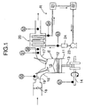
- FIG. 1 is a diagram showing the overall arrangement of a steam temperature control system for an evaporator
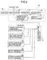
- FIG. 2 is a block diagram of the steam temperature control system for the evaporator
- FIG. 3 is a block diagram of the control system
- FIG. 4 is a flow chart for explaining the operation
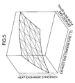
- FIG. 5 is a map for looking up the heat exchange efficiency from the exhaust gas temperature and the exhaust gas flow rate
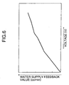
- FIG. 6 is a map for looking up, from a water supply feedback value, a voltage to be applied to a water supply regulation actuator.
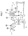
- FIG. 7 is a diagram, corresponding to FIG. 1, of a second embodiment of the present invention.
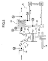
- FIG. 8 is a diagram, corresponding to FIG. 1, of a third embodiment of the present invention.
- a gasoline engine E includes a cylinder 11, a piston 12 that is slidably fitted in the cylinder 11, a connecting rod 13 having a little end connected to the piston 12, a crankshaft 14 connected to a big end of the connecting rod 13, a combustion chamber 15 defined between the cylinder 11 and the piston 12, an intake port 16 that communicates with the combustion chamber 15, an exhaust port 17 that communicates with the combustion chamber 15, a throttle valve 18 provided in the intake port 16, a fuel injection valve 19 provided in the intake port 16, and an evaporator 20 provided in the exhaust port 17.
- a Rankine cycle system R for recovering pressure energy and thermal energy of exhaust gas of the engine E and converting them into mechanical energy includes the evaporator 20 for generating steam as a gas-phase working medium by heating water as a liquid-phase working medium using the exhaust gas of the engine E, an expander 21 for receiving a supply of high temperature, high pressure steam generated by the evaporator 20 and outputting mechanical energy, a condenser 22 for cooling decreased temperature, decreased pressure steam that has been discharged from the expander 21 so as to turn it back into water, a water supply pump 23 for supplying to the evaporator 20 water that has been discharged from the condenser 22, and a water supply regulation actuator 24 for controlling the amount of water supplied to the water supply pump 23.
- inlet side exhaust gas temperature detection means S1 for detecting the temperature of the exhaust gas on the inlet side of the evaporator 20
- outlet side exhaust gas temperature detection means S2 for detecting the temperature of the exhaust gas on the outlet side of the evaporator 20
- water temperature detection means S3 for detecting the temperature of the water on the inlet side of the evaporator 20
- steam temperature detection means S4 for detecting the temperature of the steam on the outlet side of the evaporator 20
- fuel injection quantity detection means S5 for detecting the fuel injection quantity of the fuel injection valve 19 of the engine E
- air/fuel ratio detection means S6 for detecting the air/fuel ratio of the engine E
- rotational speed detection means S7 for detecting the rotational speed of the engine E.
- the inlet side exhaust gas temperature detection means S1, the outlet side exhaust gas temperature detection means S2, the water temperature detection means S3, the steam temperature detection means S4, the fuel injection quantity detection means S5, the air/fuel ratio detection means S6, and the rotational speed detection means S7 are connected to steam temperature control means U for controlling the water supply regulation actuator 24.
- engine exhaust gas flow rate calculation means M1 calculates an exhaust gas flow rate Gmix of the engine E.
- an exhaust gas enthalpy difference dHgas is calculated by exhaust gas enthalpy difference calculation means M2
- a steam enthalpy difference dHevp is calculated by steam enthalpy difference calculation means M3.
- a water supply base value Qevp of the water supply regulation actuator 24 is calculated.
- evaporator heat exchange efficiency map lookup means M6 applies the exhaust gas flow rate Gmix and the inlet side exhaust gas temperature to the map shown in FIG. 5 so as to look up the evaporator heat exchange efficiency.
- multiplication means 31 calculated a water supply feedforward value by multiplying the water supply base value Qevp by the evaporator heat exchange efficiency.
- subtraction means 32 calculates a deviation, from a target steam temperature, of the steam temperature detected by the steam temperature detection means S4, and addition means 34 calculates a water supply feedback value by adding the water supply feedforward value to a PID control level obtained by PID operation means 33 using the above deviation.
- water supply DA conversion map lookup means M7 applies the water supply feedback value to the map shown in FIG. 6 so as to carry out DA conversion into voltage; this voltage is applied to the water supply regulation actuator 24 so as to control the amount of water supplied to the evaporator 20, and the steam temperature of the evaporator 20 is thus made to coincide with the target steam temperature.
- the exhaust gas flow rate Gmix which is a parameter with which the temperature of steam generated by the evaporator 20 is controlled at a target steam temperature, is calculated based on the fuel injection quantity, the air/fuel ratio, and the rotational speed of the engine E, when the output of the engine E is in a transition state (for example, changing from combustion at the theoretical air/fuel ratio to lean burn), the exhaust gas flow rate Gmix can be calculated with high precision. Moreover, since the exhaust gas flow rate Gmix can be calculated regardless of the specifications of the engine E, the amount of water supplied to the expander 20 can be determined using the same calculation setup data.
- the method for determining the exhaust gas flow rate Gmix by calculation is different from that of the first embodiment, but the rest of the structure and the operation are the same as those of the first embodiment.
- an exhaust gas flow rate Gmix there are provided, as engine operating conditions detection means, fuel injection quantity detection means S5 for detecting the amount of fuel injected per unit time and intake air volume detection means S8 (air flow meter) for detecting the mass flow rate of the intake air.
- the method for determining the exhaust gas flow rate Gmix by calculation is different from that of the first embodiment, but the rest of the structure and the operation are the same as those of the first embodiment.
- an exhaust gas flow rate Gmix there are provided, as engine operating conditions detection means, air/fuel ratio detection means S6 for detecting an air/fuel ratio of an engine E, and intake air volume detection means S8 (air flow meter) for detecting the mass flow rate of the intake air.
- water and steam are used as the liquid-phase working medium and the gas-phase working medium, but the present invention can be applied to any other working medium.
- first embodiment to third embodiment can be applied not only to a gasoline engine but also to a common-rail diesel engine and, moreover, the third embodiment can be applied to a distributor type diesel engine or an in-line type diesel engine.
- the present invention can be desirably applied to an evaporator for a Rankine cycle system for converting the thermal energy of the exhaust gas of an engine into mechanical energy, but can also be applied to an evaporator for any other use.
Applications Claiming Priority (3)
| Application Number | Priority Date | Filing Date | Title |
|---|---|---|---|
| JP2001301626 | 2001-09-28 | ||
| JP2001301626 | 2001-09-28 | ||
| PCT/JP2002/009724 WO2003029619A1 (fr) | 2001-09-28 | 2002-09-20 | Dispositif de commande thermique d'un evaporateur |
Publications (2)
| Publication Number | Publication Date |
|---|---|
| EP1431523A1 true EP1431523A1 (de) | 2004-06-23 |
| EP1431523A4 EP1431523A4 (de) | 2005-03-16 |
Family
ID=19122006
Family Applications (1)
| Application Number | Title | Priority Date | Filing Date |
|---|---|---|---|
| EP02775223A Withdrawn EP1431523A4 (de) | 2001-09-28 | 2002-09-20 | Temperaturregelvorrichtung für verdampfer |
Country Status (4)
| Country | Link |
|---|---|
| US (1) | US7007473B2 (de) |
| EP (1) | EP1431523A4 (de) |
| JP (1) | JPWO2003029619A1 (de) |
| WO (1) | WO2003029619A1 (de) |
Cited By (9)
| Publication number | Priority date | Publication date | Assignee | Title |
|---|---|---|---|---|
| WO2005108750A3 (en) * | 2004-05-06 | 2006-05-26 | United Technologies Corp | Startup and control methods for an orc bottoming plant |
| FR2884556A1 (fr) * | 2005-04-13 | 2006-10-20 | Peugeot Citroen Automobiles Sa | Dispositif de recuperation d'energie d'un moteur a combustion interne |
| EP1925806A2 (de) | 2006-11-24 | 2008-05-28 | Behr GmbH & Co. KG | System mit einem Organic-Rankine-Kreislauf zum Antrieb zumindest einer Expansionsmaschine, Wärmetauscher zum Antrieb einer Expansionsmaschine, Verfahren zum Betreiben zumindest einer Expansionsmaschine |
| WO2009106563A2 (de) * | 2008-02-26 | 2009-09-03 | Alstom Technology Ltd | Verfahren zur regelung eines dampferzeugers und regelschaltung für einen dampferzeuger |
| WO2009109311A2 (de) * | 2008-03-06 | 2009-09-11 | Daimler Ag | Verfahren zum gewinnen von energie aus einem abgasstrom sowie kraftfahrzeug |
| DE102009020615A1 (de) | 2009-05-09 | 2010-11-11 | Daimler Ag | Abgaswärmenutzung in Kraftfahrzeugen |
| AT511189A4 (de) * | 2011-07-14 | 2012-10-15 | Avl List Gmbh | Verfahren zur regelung einer wärmenutzungsvorrichtung bei einer brennkraftmaschine |
| EP2693001A1 (de) * | 2012-07-31 | 2014-02-05 | MAN Truck & Bus Österreich AG | Verfahren zur Regelung eines Wärme-Rückgewinnungs-Systems in einem Kraftfahrzeug |
| WO2019007622A1 (de) * | 2017-07-05 | 2019-01-10 | Robert Bosch Gmbh | Leistungsoptimierer für abwärmerückgewinnungssystem |
Families Citing this family (13)
| Publication number | Priority date | Publication date | Assignee | Title |
|---|---|---|---|---|
| JP4543920B2 (ja) * | 2004-12-22 | 2010-09-15 | 株式会社デンソー | 熱機関の廃熱利用装置 |
| JP2006250074A (ja) * | 2005-03-11 | 2006-09-21 | Honda Motor Co Ltd | ランキンサイクル装置 |
| JP4345752B2 (ja) * | 2006-02-02 | 2009-10-14 | トヨタ自動車株式会社 | 排熱回収装置 |
| EP2065641A3 (de) * | 2007-11-28 | 2010-06-09 | Siemens Aktiengesellschaft | Verfahren zum Betrieben eines Durchlaufdampferzeugers sowie Zwangdurchlaufdampferzeuger |
| US8881523B2 (en) * | 2008-08-26 | 2014-11-11 | Sanden Corporation | Waste heat utilization device for internal combustion engine |
| DE102008041874A1 (de) * | 2008-09-08 | 2010-03-11 | Robert Bosch Gmbh | Vorrichtung und Verfahren zum Betreiben einer Brennkraftmaschine, Computerprogramm, Computerprogrammprodukt |
| DE102011076968A1 (de) * | 2011-06-06 | 2012-12-06 | Siemens Aktiengesellschaft | Verfahren zum Betreiben eines Umlauf-Abhitzedampferzeugers |
| US9551487B2 (en) | 2012-03-06 | 2017-01-24 | Access Energy Llc | Heat recovery using radiant heat |
| DE102012206466A1 (de) * | 2012-04-19 | 2013-10-24 | Siemens Aktiengesellschaft | Verfahren und Vorrichtung zum Betrieb eines solarthermischen Kraftwerks |
| CN103573353A (zh) * | 2012-07-18 | 2014-02-12 | 陕西重型汽车有限公司 | 汽车发动机尾气自动烧水装置 |
| CN102748124A (zh) * | 2012-07-26 | 2012-10-24 | 湖南大学 | 一种利用内燃机废气余热能实现进气增压的装置 |
| US20140224469A1 (en) * | 2013-02-11 | 2014-08-14 | Access Energy Llc | Controlling heat source fluid for thermal cycles |
| EP3647657A1 (de) * | 2018-10-29 | 2020-05-06 | Siemens Aktiengesellschaft | Speisewasserregelung für zwangdurchlauf-abhitzedampferzeuger |
Family Cites Families (15)
| Publication number | Priority date | Publication date | Assignee | Title |
|---|---|---|---|---|
| JPS6064101A (ja) | 1983-09-20 | 1985-04-12 | 川崎重工業株式会社 | 貫流ボイラの制御装置 |
| US4586338A (en) * | 1984-11-14 | 1986-05-06 | Caterpillar Tractor Co. | Heat recovery system including a dual pressure turbine |
| JP2669659B2 (ja) * | 1988-07-29 | 1997-10-29 | マツダ株式会社 | 車両用エアバッグ制御装置 |
| JPH0238162A (ja) * | 1988-07-29 | 1990-02-07 | Mazda Motor Corp | 車両用エアバッグ制御装置 |
| SE515966C2 (sv) * | 1994-06-20 | 2001-11-05 | Ranotor Utvecklings Ab | Motoraggregat omfattande en förbränningsmotor och en ångmotor |
| JP3551697B2 (ja) * | 1997-05-15 | 2004-08-11 | 日産自動車株式会社 | ディーゼルエンジンの制御装置 |
| EP0884550A3 (de) * | 1997-06-13 | 1999-12-15 | Isuzu Ceramics Research Institute Co., Ltd. | Wärmetauscher, Wärmeaustauschvorrichtung für Gasmotor |
| JP2000073753A (ja) * | 1998-09-01 | 2000-03-07 | Nissan Motor Co Ltd | 内燃機関の廃熱回収装置 |
| JP2000311680A (ja) | 1999-04-26 | 2000-11-07 | Matsushita Electric Ind Co Ltd | ニッケル水素電池用焼結型正極板とその製造方法およびニッケル水素電池 |
| JP2000345835A (ja) * | 1999-06-07 | 2000-12-12 | Nissan Motor Co Ltd | 内燃機関 |
| JP2001132538A (ja) * | 1999-11-04 | 2001-05-15 | Hideo Kawamura | エネルギ回収装置を備えたエンジン |
| JP2001227616A (ja) * | 1999-12-08 | 2001-08-24 | Honda Motor Co Ltd | 駆動装置 |
| JP2001271609A (ja) * | 2000-01-18 | 2001-10-05 | Honda Motor Co Ltd | 内燃機関の廃熱回収装置 |
| JP2002115801A (ja) | 2000-10-05 | 2002-04-19 | Honda Motor Co Ltd | 蒸発器の蒸気温度制御装置 |
| DE60123987T2 (de) * | 2000-10-10 | 2007-02-01 | Honda Giken Kogyo K.K. | Rankine-kreislaufvorrichtung für verbrennungsmotor |
-
2002
- 2002-09-20 WO PCT/JP2002/009724 patent/WO2003029619A1/ja not_active Application Discontinuation
- 2002-09-20 EP EP02775223A patent/EP1431523A4/de not_active Withdrawn
- 2002-09-20 JP JP2003532811A patent/JPWO2003029619A1/ja not_active Withdrawn
- 2002-09-20 US US10/490,766 patent/US7007473B2/en not_active Expired - Fee Related
Non-Patent Citations (2)
| Title |
|---|
| No further relevant documents disclosed * |
| See also references of WO03029619A1 * |
Cited By (19)
| Publication number | Priority date | Publication date | Assignee | Title |
|---|---|---|---|---|
| WO2005108750A3 (en) * | 2004-05-06 | 2006-05-26 | United Technologies Corp | Startup and control methods for an orc bottoming plant |
| FR2884556A1 (fr) * | 2005-04-13 | 2006-10-20 | Peugeot Citroen Automobiles Sa | Dispositif de recuperation d'energie d'un moteur a combustion interne |
| EP1925806A2 (de) | 2006-11-24 | 2008-05-28 | Behr GmbH & Co. KG | System mit einem Organic-Rankine-Kreislauf zum Antrieb zumindest einer Expansionsmaschine, Wärmetauscher zum Antrieb einer Expansionsmaschine, Verfahren zum Betreiben zumindest einer Expansionsmaschine |
| WO2009106563A3 (de) * | 2008-02-26 | 2010-11-11 | Alstom Technology Ltd | Verfahren zur regelung eines dampferzeugers und regelschaltung für einen dampferzeuger |
| WO2009106563A2 (de) * | 2008-02-26 | 2009-09-03 | Alstom Technology Ltd | Verfahren zur regelung eines dampferzeugers und regelschaltung für einen dampferzeuger |
| US10167743B2 (en) | 2008-02-26 | 2019-01-01 | General Electric Technology Gmbh | Method for controlling a steam generator and control circuit for a steam generator |
| US8572964B2 (en) | 2008-03-06 | 2013-11-05 | Daimler Ag | Method for recuperating energy from an exhaust gas flow and motor vehicle |
| WO2009109311A3 (de) * | 2008-03-06 | 2011-05-19 | Daimler Ag | Verfahren zum gewinnen von energie aus einem abgasstrom sowie entsprechendes kraftfahrzeug |
| WO2009109311A2 (de) * | 2008-03-06 | 2009-09-11 | Daimler Ag | Verfahren zum gewinnen von energie aus einem abgasstrom sowie kraftfahrzeug |
| WO2010130317A3 (de) * | 2009-05-09 | 2011-10-13 | Daimler Ag | Abgaswärmenutzung in kraftfahrzeugen |
| DE102009020615A1 (de) | 2009-05-09 | 2010-11-11 | Daimler Ag | Abgaswärmenutzung in Kraftfahrzeugen |
| AT511189A4 (de) * | 2011-07-14 | 2012-10-15 | Avl List Gmbh | Verfahren zur regelung einer wärmenutzungsvorrichtung bei einer brennkraftmaschine |
| AT511189B1 (de) * | 2011-07-14 | 2012-10-15 | Avl List Gmbh | Verfahren zur regelung einer wärmenutzungsvorrichtung bei einer brennkraftmaschine |
| WO2013007530A1 (de) | 2011-07-14 | 2013-01-17 | Avl List Gmbh | Verfahren zur regelung einer wärmenutzungsvorrichtung bei einer brennkraftmaschine |
| EP2732140A1 (de) * | 2011-07-14 | 2014-05-21 | AVL List GmbH | Verfahren zur regelung einer wärmenutzungsvorrichtung bei einer brennkraftmaschine |
| EP2732140B1 (de) * | 2011-07-14 | 2021-08-11 | AVL List GmbH | Verfahren zur regelung einer wärmenutzungsvorrichtung bei einer brennkraftmaschine |
| EP2693001A1 (de) * | 2012-07-31 | 2014-02-05 | MAN Truck & Bus Österreich AG | Verfahren zur Regelung eines Wärme-Rückgewinnungs-Systems in einem Kraftfahrzeug |
| RU2638890C2 (ru) * | 2012-07-31 | 2017-12-18 | МАН Трак унд Бас Эстеррайх АГ | Способ регулирования системы утилизации тепла в транспортном средстве |
| WO2019007622A1 (de) * | 2017-07-05 | 2019-01-10 | Robert Bosch Gmbh | Leistungsoptimierer für abwärmerückgewinnungssystem |
Also Published As
| Publication number | Publication date |
|---|---|
| US20050050909A1 (en) | 2005-03-10 |
| JPWO2003029619A1 (ja) | 2005-01-20 |
| WO2003029619A1 (fr) | 2003-04-10 |
| US7007473B2 (en) | 2006-03-07 |
| EP1431523A4 (de) | 2005-03-16 |
Similar Documents
| Publication | Publication Date | Title |
|---|---|---|
| EP1431523A1 (de) | Temperaturregelvorrichtung für verdampfer | |
| US7418857B2 (en) | Air quantity estimation apparatus for internal combustion engine | |
| US7457701B2 (en) | Air quantity estimation apparatus for internal combustion engine | |
| KR100533566B1 (ko) | 내연 기관용 연료 분사량 제어 시스템 | |
| US7079937B2 (en) | Air quantity estimation apparatus for internal combustion engine | |
| JP3804814B2 (ja) | 内燃機関の燃料供給装置 | |
| US8572964B2 (en) | Method for recuperating energy from an exhaust gas flow and motor vehicle | |
| CN101182797A (zh) | 兰金循环系统和液压储能系统的组合 | |
| CN103573468A (zh) | 用于控制机动车辆中的热回收系统的方法 | |
| US10626808B2 (en) | Controlling fuel injection in an internal combustion engine | |
| EP1004764B1 (de) | Verfahren zur Steuerung der Einspritzung in den Brennkammer einer Brennkraftmaschine | |
| JP2017145799A (ja) | ランキンサイクルシステム | |
| JP3901608B2 (ja) | ランキンサイクル装置 | |
| US20060168963A1 (en) | Rankine cycle system | |
| WO2009107372A1 (ja) | 内燃機関の燃料噴射量を制御するための装置 | |
| US20060201153A1 (en) | Rankine cycle system | |
| US20050279322A1 (en) | Method and control unit for creating an injection pulse width | |
| JP3865767B2 (ja) | 内燃機関高圧噴射装置用噴射制御装置 | |
| WO2002059465A1 (fr) | Alimentation de milieu actif et dispositif de commande pour echangeur thermique | |
| US5755208A (en) | Method of controlling a non-return fuel supply system for an internal combustion engine and a supply system for working the said method | |
| US20060191678A1 (en) | Evaporator control system | |
| JP2007332864A (ja) | 内燃機関の燃料噴射量制御装置 | |
| JP2014015893A (ja) | 燃料噴射量補正における補正量制御方法及びコモンレール式燃料噴射制御装置 | |
| JP2010096162A (ja) | 内燃機関の燃料噴射制御装置 | |
| JPH09303175A (ja) | エンジンの燃料噴射装置 |
Legal Events
| Date | Code | Title | Description |
|---|---|---|---|
| PUAI | Public reference made under article 153(3) epc to a published international application that has entered the european phase |
Free format text: ORIGINAL CODE: 0009012 |
|
| 17P | Request for examination filed |
Effective date: 20040326 |
|
| AK | Designated contracting states |
Kind code of ref document: A1 Designated state(s): AT BE BG CH CY CZ DE DK EE ES FI FR GB GR IE IT LI LU MC NL PT SE SK TR |
|
| A4 | Supplementary search report drawn up and despatched |
Effective date: 20050127 |
|
| GRAP | Despatch of communication of intention to grant a patent |
Free format text: ORIGINAL CODE: EPIDOSNIGR1 |
|
| RBV | Designated contracting states (corrected) |
Designated state(s): DE GB |
|
| STAA | Information on the status of an ep patent application or granted ep patent |
Free format text: STATUS: THE APPLICATION IS DEEMED TO BE WITHDRAWN |
|
| 18D | Application deemed to be withdrawn |
Effective date: 20061228 |