EP1430922B1 - Vorrichtung zum Temperieren von in einem Schlauch geführter Flüssigkeit - Google Patents
Vorrichtung zum Temperieren von in einem Schlauch geführter Flüssigkeit Download PDFInfo
- Publication number
- EP1430922B1 EP1430922B1 EP03025861A EP03025861A EP1430922B1 EP 1430922 B1 EP1430922 B1 EP 1430922B1 EP 03025861 A EP03025861 A EP 03025861A EP 03025861 A EP03025861 A EP 03025861A EP 1430922 B1 EP1430922 B1 EP 1430922B1
- Authority
- EP
- European Patent Office
- Prior art keywords
- winding body
- tube
- groove
- hose
- guide
- Prior art date
- Legal status (The legal status is an assumption and is not a legal conclusion. Google has not performed a legal analysis and makes no representation as to the accuracy of the status listed.)
- Expired - Lifetime
Links
- 239000012530 fluid Substances 0.000 title description 3
- 238000004804 winding Methods 0.000 claims abstract description 29
- 239000010836 blood and blood product Substances 0.000 claims abstract description 7
- 229940125691 blood product Drugs 0.000 claims abstract description 7
- 239000003978 infusion fluid Substances 0.000 claims abstract description 7
- 239000007788 liquid Substances 0.000 claims abstract description 4
- 230000002093 peripheral effect Effects 0.000 abstract description 2
- 230000007423 decrease Effects 0.000 abstract 1
- 238000010792 warming Methods 0.000 abstract 1
- 238000010438 heat treatment Methods 0.000 description 6
- 238000003780 insertion Methods 0.000 description 4
- 230000037431 insertion Effects 0.000 description 4
- 210000004369 blood Anatomy 0.000 description 3
- 239000008280 blood Substances 0.000 description 3
- 238000001802 infusion Methods 0.000 description 3
- 239000012141 concentrate Substances 0.000 description 2
- 210000003743 erythrocyte Anatomy 0.000 description 2
- 238000012546 transfer Methods 0.000 description 2
- 230000036760 body temperature Effects 0.000 description 1
- 230000001143 conditioned effect Effects 0.000 description 1
- 230000006378 damage Effects 0.000 description 1
- 230000003247 decreasing effect Effects 0.000 description 1
- 238000013461 design Methods 0.000 description 1
- 239000011888 foil Substances 0.000 description 1
- 238000005259 measurement Methods 0.000 description 1
- 238000012544 monitoring process Methods 0.000 description 1
- 230000007704 transition Effects 0.000 description 1
- 210000003462 vein Anatomy 0.000 description 1
- 238000011179 visual inspection Methods 0.000 description 1
- 238000005303 weighing Methods 0.000 description 1
Images



Classifications
-
- A—HUMAN NECESSITIES
- A61—MEDICAL OR VETERINARY SCIENCE; HYGIENE
- A61M—DEVICES FOR INTRODUCING MEDIA INTO, OR ONTO, THE BODY; DEVICES FOR TRANSDUCING BODY MEDIA OR FOR TAKING MEDIA FROM THE BODY; DEVICES FOR PRODUCING OR ENDING SLEEP OR STUPOR
- A61M5/00—Devices for bringing media into the body in a subcutaneous, intra-vascular or intramuscular way; Accessories therefor, e.g. filling or cleaning devices, arm-rests
- A61M5/44—Devices for bringing media into the body in a subcutaneous, intra-vascular or intramuscular way; Accessories therefor, e.g. filling or cleaning devices, arm-rests having means for cooling or heating the devices or media
Definitions
- the invention relates to a device for temperature control of guided in a tube liquid, in particular a blood product or an infusion solution, comprising a winding body having along the circumference of its lateral surface extending, spiral or thread-like, a guide passage for receiving the wound hose forming grooves.
- Blood products such as packed red blood cells or whole blood
- the infusion solutions used are stored either in a refrigerator at 2 to 6 ° C or at room temperature of about 20 ° C.
- these intravenously administered to a patient via a venous access fluids must be heated so that they are at the time of vein entry body warm (35 to 37 ° C).
- up to 105 ml red blood cell concentrate per minute may be administered, which must be conditioned to body temperature with the aid of a 4 ° C. initial temperature warmer.
- a generic device For heating the blood or an infusion solution on its way from the storage container to the venous access a generic device has become known from DE 197 40 177 A1, in which the hose winder is formed as a cylindrical body with a spiral peripheral thread as guide channels for the hose. On the cylindrical body, a plug for the electrical power supply to a heater and a control panel with control and display devices for the control of the heater is provided.
- the cylindrical bobbin is attached with its back in a horizontal position on an IV pole and the tube is inserted by hand from back to front in the groove of the guide rail. So that the tube is fixed in the inserted state within the groove, this is provided with a narrowing in the radial direction from the inside to the outside. To reach the hose in its position without external force position secure position in the groove, it must be completely drawn into the groove to the groove bottom during wrapping under constant directional force. This careful insertion into the groove causes considerable difficulties. For a standing in front of the bobbin and her gaze does not change person has no clear view of the entire surface of the cylindrical bobbin. Finding the groove and the correct insertion of the tube into the groove bottom is therefore difficult.
- the invention is therefore an object of the invention to provide a generic device without the disadvantages mentioned, in particular so educate that can be a longer hose with less effort and also safe to wind up.
- the winding body is formed from its rear side with an oblique, with a taper angle relative to its center line sloping lateral surface, all grooves of the guide passage from a viewing position are visible.
- the user can survey the entire lateral surface of, for example, the truncated cone-like or even truncated-pyramidal or, if appropriate, an oval base surface having a wound body.
- the operator can without an annoying rotational movement of the head at the same time Always look at the outer surface of the hose and optimally on its correct positioning in each guide or each groove focus.
- the obliquely from front to back or sloping lateral surface of the bobbin supports the movement or slipping of the tube in the next free groove of the guide.
- the rotational movement of the hand around the winding body causes namely a directed force on the hose, so that an accidentally by the user or by the operator far above the free Folgeut wrapped around the bobbin tube section automatically slides into the correct position of the free Folgeut.
- a groove of the guide superimposed tube layers are excluded.
- a winding body 1 according to FIGS. 1 and 2 and 5 is connected to the supply of heating energy to a heating source (not shown) and is suspended with a clamping device 2 to a likewise not shown infusion stand in about 1.5 to 2 m height. It is formed from its rear side 3 with a continuously decreasing diameter toward the front and with grooves 5 of a spiral-like guide channel 6 extending along its circumference in its lateral surface for receiving a successively inserted hose 4 (see FIGS and 4). Due to the inclined plane of the winding body 1 is formed between the surface line 7 and its center line 8, a taper angle ⁇ , as shown in Fig. 2. The measured perpendicular to the center line 8 distance between the center line 8 and the surface line 7 is consequently reduced over the entire circumference of the bobbin 1 steadily forward.
- To supply with heating energy can on the inner circumferential surface 10 of the hollow bobbin. 1
- a foil heating element are glued, which defines the bobbin 1 preselected tempered.
- the winding body 1 is designed so that the distance 13 between the gaze position 11 and the rear groove 5 of the guide 6 is about 50 cm.
- the angle ⁇ a range of values of about 5 to 20 ° and for the taper angle ⁇ a lower limit of 5 °; the upper limit can be assumed to be 45 ° for design reasons.
- the operator can without annoying rotational movement of the head and effortlessly insert the respective tube section in the associated groove 5 and optimally concentrate on the correct positioning of each tube section, which is always freely in sight.
- the grooves 5 and the guide 6 are introduced with a constant depth in the winding body 1, as shown in FIG. 3 can be seen.
- the shape of the lateral surface is defined by a contour line 13, wherein the groove 5 is bounded by an upper and a lower groove point 14 and 15 respectively.
- the groove points 14 and 15 are the points on the contour line 13, where this leaves the direction of the surface line 7 and merges into the groove 5.
- This transition can be angular with an edge (as in FIG. 3), angular with a plurality of edges, for example with a chamfer, or round, for example with a radius.
- Each groove 5 finds an upper and a lower boundary line
- the depth of the grooves 5 of the guide 6 is thus determined so that the inserted into a groove 5 hose 4 with its highest elevation 18 in the radial direction neither the Upper boundary line 16 still exceeds the lower boundary line 17 below.
- the exact location of the inserted into the grooves 5 of the guide 6 tube 4 is thus guaranteed.
- the oblique lateral surface of the winding body 1 offers an insertion aid for the hose 4, since the movement of the hose section to be inserted into the next free groove is supported.
- the rotational movement of the hand around the winding body 1 causes a directed force 19 on the tube 4, so that a hose section 4 ', which is accidentally placed by the user far above the free groove n + 1 around the winding body, as illustrated by the position a, from above the groove position n automatically slips into the next free groove n + 1, as illustrated by the introduction sequences a to d.
- the winding body 1 offers the possibility of putting on an easy-to-handle thermal sleeve 20, which covers the entire lateral surface and which additionally heats the hose surface not engaging the winding body.
- the heat cuff 20 can be used as a passive heating element if, according to FIG. 6, it has contact in the applied state both over the surfaces 21 between adjacent grooves 5 of the guide channel 6 and to the tube 4 over a surface 22.
- the heat cuff 20 may be in one piece for the forward sloping bobbin 1. On the front side, it has an opening 23 which allows access to the operating and display unit 9.
- the heat cuff 20 can be mechanically connected via a rotary joint 24 with the back or wall 3 of the winding body 1, so that they are in open state hangs down freely. To create it then needs to be pivoted only upwards and there can be determined by means of a closure element 25 on the winding body 1.
- the closure element 25 pulls the heat cuff 20 in the direction of the winding body back 3 and thus ensures that it touches both the lateral surface and the hose line.
Landscapes
- Health & Medical Sciences (AREA)
- Animal Behavior & Ethology (AREA)
- Veterinary Medicine (AREA)
- Anesthesiology (AREA)
- Biomedical Technology (AREA)
- Heart & Thoracic Surgery (AREA)
- Hematology (AREA)
- Engineering & Computer Science (AREA)
- General Health & Medical Sciences (AREA)
- Life Sciences & Earth Sciences (AREA)
- Public Health (AREA)
- Vascular Medicine (AREA)
- Infusion, Injection, And Reservoir Apparatuses (AREA)
- Thermotherapy And Cooling Therapy Devices (AREA)
- Heat Treatment Of Articles (AREA)
- External Artificial Organs (AREA)
Description
- Die Erfindung betrifft eine Vorrichtung zum Temperieren von in einem Schlauch geführter Flüssigkeit, insbesondere ein Blutprodukt oder eine Infusionslösung, umfassend einen Wickelkörper mit sich entlang des Umfangs seiner Mantelfläche erstreckenden, spiral- oder gewindeartigen, einen Führungsgang zur Aufnahme des aufgewickelten Schlauches bildenden Nuten.
- Blutprodukte, wie Erythrozytenkonzentrat oder Vollblut, werden in der Regel mit üblichen Temperaturen von 2 bis 6°C kalt gelagert, um die Haltbarkeit zu erhöhen. Die zur Verwendung kommenden Infusionslösungen werden entweder in einem Kühlschrank bei 2 bis 6°C oder bei Raumtemperatur von etwa 20°C aufbewahrt. Diese einem Patienten intravenös über einen Venenzugang zugeführten Flüssigkeiten müssen aber so erwärmt werden, daß sie zum Zeitpunkt des Veneneintritts körperwarm (35 bis 37°C) sind. Bei Verletzungen mit hohem Blutverlust, hervorgerufen durch mehrere Körperöffnungen, kann es erforderlich sein, eine große Menge des Blutproduktes innerhalb einer sehr kurzen Zeit zu erwärmen. Bei einem Patienten mit einem Körpergewicht von 70 kg können bis zu 105 ml Erythrozytenkonzentrat pro Minute verabreicht werden, das mit Hilfe einer Erwärmvorrichtung von 4°C Anfangstemperatur auf Körpertemperatur temperiert werden muß.
- Es ist üblich, in Kunststoffbeuteln abgefüllte Blutprodukte oder in Flaschen bzw. Kunststoffbeuteln bevorratete Infusionslösungen an einen Infusionsständer in etwa 1,5 bis 2 m Höhe aufzuhängen. Von dort strömt das Blutprodukt bzw. die Infusionslösung durch einen sogenannten Infusionsschlauch zum Venenzugang.
- Zur Erwärmung des Blutes bzw. einer Infusionslösung auf seinem Weg vom Bevorratungsbehältnis bis zum Venenzugang ist durch die DE 197 40 177 A1 eine gattungsgemäße Vorrichtung bekanntgeworden, bei der der Schlauchwickler als zylindrischer Körper mit einem spiralförmigen Umfangsgewinde als Führungsgänge für den Schlauch ausgebildet ist. An dem zylindrischen Körper ist ein Stecker für die elektrische Energiezufuhr zu einer Heizvorrichtung sowie ein Bedienfeld mit Regel- und Anzeigevorrichtungen für die Steuerung der Heizvorrichtung vorgesehen.
- Der zylindrische Wickelkörper wird mit seiner Rückseite in waagerechter Position an einem Infusionsständer befestigt und der Schlauch von Hand von hinten nach vorne in die Nut des Führungsgangs eingelegt. Damit der Schlauch im eingelegten Zustand innerhalb der Nut fixiert wird, ist diese mit einer Verengung in radialer Richtung von innen nach außen versehen. Um den Schlauch in seine ohne äußere Krafteinwirkung lagesichere Position in der Nut gelangen kann, muß er beim Einwickeln unter ständiger gerichteter Krafteinwirkung vollständig in die Nut bis zum Nutgrund hineingezogen werden. Dieses sorgfältige Einlegen in die Nut bereitet erhebliche Schwierigkeiten. Denn eine vor dem Wickelkörper stehende und ihre Blickposition nicht verändernde Person hat keine freie Sicht auf die gesamte Oberfläche des zylindrischen Wickelkörpers. Das Finden der Nut sowie das korrekte Einlegen des Schlauchs bis in den Nutgrund ist daher nur schwer möglich. Das wird umso problematischer, je länger der aufzuwickelnde Schlauch ist, wobei ein Schlauch mit großer Länge wegen der dann über einen längeren Zeitraum bzw. Weg einzubringenden höheren Heizenergie angestrebt wird, weil der Durchmesser des Wickelkörpers und/oder dessen Länge vergrößert werden müßten.
- Bei im Markt befindlichen Schlauchwickelwärmern sind Durchmesser des zylindrischen Wickelkörpers und Nutlänge so ausgelegt, daß ein Schlauch mit 3,5 m Länge eingelegt werden kann, was es mit sich bringt, daß dieser mindestens neunmal um den Wickelkörper geführt werden muß. Das zum sorgfältigen Einlegen des Schlauches in die Nut notwendige punktgenaue Beobachten des Schlauchs bedingt somit, daß der Blickpunkt des Anwenders permanent in entsprechend großer Zahl ebenfalls um den Wickelkörper kreisen muß. Da diese Rotationsbewegung des Kopfes als ausgesprochen unangenehm empfunden wird, bleibt eine Sichtkontrolle häufig aus. Damit ist dann allerdings nicht sichergestellt, daß der Schlauch vollständig in die richtige Nut eingelegt ist, so daß es häufig zu in einem Nutgang übereinanderliegenden Schlauchwicklungen kommt. Ein falsch eingelegter Schlauch hat eine erheblich reduzierte Kontaktfläche zum Heizkörper, so daß die Wärmeübertragung und damit die Endtemperatur der Infusions- bzw. Transfusionsflüssigkeit verringert wird. Da am Venenzugang keine Messung der Flüssigkeitstemperatur erfolgt, bleibt dies zum Nachteil des Patienten unbemerkt.
- Der Erfindung liegt daher die Aufgabe zugrunde, eine gattungsgemäße Vorrichtung ohne die genannten Nachteile zu schaffen, insbesondere so weiterzubilden, daß sich ein längerer Schlauch mit zudem weniger Aufwand und außerdem sicher aufwickeln läßt.
- Diese Aufgabe wird erfindungsgemäß dadurch gelöst, daß der Wickelkörper von seiner Rückseite her mit einer schiefen, unter einem Verjüngungswinkel bezogen auf seine Mittellinie abfallenden Mantelfläche ausgebildet ist, wobei alle Nuten des Führungsgangs aus einer Blickposition einsehbar sind. Hiermit lassen sich mehrere Vorteile gleichzeitig erreichen. Der Anwender kann die gesamte Mantelfläche des z.B. kegelstumpfartigen oder auch pyramidenstumpfartigen bzw. gegebenenfalls eine ovale Grundfläche aufweisenden Wickelkörpers überblicken. Das Bedienungspersonal kann ohne eine lästige Rotationsbewegung des Kopfes bei gleichwohl stets freiem Blick auf die Mantelfläche den Schlauch einlegen und sich optimal auf dessen korrekte Positionierung in jedem Führungsgang bzw. jeder Nut konzentrieren. Die von vorne nach hinten schiefe bzw. abfallende Mantelfläche des Wickelkörpers unterstützt die Bewegung bzw. das Abgleiten des Schlauchs in die nächste freie Nut des Führungsgangs. Die Rotationsbewegung der Hand um den Wickelkörper verursacht nämlich eine gerichtete Kraft auf den Schlauch, so daß ein vom Anwender bzw. von der Bedienungsperson versehentlich weit oberhalb der freien Folgenut um den Wickelkörper gelegter Schlauchabschnitt selbsttätig in die richtige Position der freien Folgenut rutscht. Damit sind in einer Nut des Führungsgangs übereinanderliegende Schlauchlagen ausgeschlossen.
- Da die gesamte Wickelkörper-Mantelfläche aufgrund der Verjüngung nach vorne hin im freien Blickfeld der Bedienungsperson liegt, kann weiterhin auch sofort festgestellt werden, ob mitunter nicht auszuschließende Lufteinschlüsse aufgetreten sind. Insgesamt ergibt sich somit, daß nicht nur eine erheblich verbesserte Bedienfreundlichkeit gegeben ist, da dem Anwender bzw. der Bedienungsperson eine nur noch geringe Aufmerksamkeit und Konzentration abgefordert wird, sondern auch die Sicherheit in der Anwendung erhöht wird.
- Weitere Einzelheiten und Merkmale der Erfindung ergeben sich aus dem Patentanspruch und der nachfolgenden Beschreibung von in den Zeichnungen dargestellten Ausführungsbeispielen der Erfindung. Es zeigen:
- Fig. 1
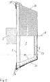
- eine Halbschnittdarstellung eines im Ausführungsbeispiel als Kegelstumpf ausgebildeten Wickelkörpers, bei der im oberen Teil die Seitenansicht auf die Oberfläche und im unteren Teil ein Querschnitt durch den Wickelkörper dargestellt ist;
- Fig. 2
- den Wickelkörper nach Fig. 1 mit Blickrichtung einer Bedienungsperson dargestellt;
- Fig. 3
- als Einzelheit des Wickelkörpers einen Querschnitt durch eine Nut des Führungsgangs mit eingelegtem Schlauch;
- Fig. 4
- die Bewegungsrichtung eines Schlauchabschnitts, der unter Krafteinwirkung selbsttätig in die nächste freie Nut des Führungsgangs fällt;
- Fig. 5
- eine Halbschnittdarstellung des Wickelkörpers mit einer aufgesetzten Wärmemanschette; und
- Fig. 6
- als Einzelheit des Wickelkörpers nach Fig. 5 eine Nut des Führungsgangs mit eingelegtem Schlauch und aufgesetzter Wärmemanschette.
- Ein Wickelkörper 1 nach den Fig. 1 sowie 2 und 5 ist zur Versorgung mit Heizenergie an eine Heizquelle angeschlossen (nicht dargestellt) und wird mit einer Klemmeinrichtung 2 an einen ebenfalls nicht gezeigten Infusionsständer in ca. 1,5 bis 2 m Höhe aufgehängt. Er ist von seiner Rückseite 3 her mit sich nach vorne hin stetig verringerndem Durchmesser ausgebildet und mit sich entlang seines Umfangs in seiner Mantelfläche erstreckenden Nuten 5 eines spiralartigen Führungsgangs 6 zur Aufnahme eines sukzessive in jede Nut 5 einzulegenden Schlauches 4 (vgl. die Fig. 3 und 4) versehen. Aufgrund der schiefen Ebene des Wickelkörpers 1 entsteht zwischen dessen Mantellinie 7 und seiner Mittellinie 8 ein Verjüngungswinkel α, wie in Fig. 2 gezeigt. Der zur Mittellinie 8 lotrecht gemessene Abstand zwischen der Mittellinie 8 und der Mantellinie 7 verringert sich folglich über den gesamten Umfang des Wickelkörpers 1 stetig nach vorne.
- An der Vorderseite des Wickelkörpers 1 befindet sich eine Bedien- und Anzeigeeinheit 9 mit Bedientasten, über die eine Bedienperson die Temperaturwerte, auf die der Wickelkörper 1 temperiert werden soll, vorwählen kann. Zur Versorgung mit Heizenergie kann auf der inneren Mantelfläche 10 des hohlen Wickelkörpers 1 beispielsweise ein Folienheizelement aufgeklebt werden, das den Wickelkörper 1 definiert vorgewählt temperiert. Es wird somit die Funktion eines Wärmetauschers erfüllt, der eine aktiv erzeugte Wärme von innen über die Nuten 5 des Führungsgangs 6 auf den eingelegten Schlauch 4 überträgt.
- Das für eine Bedienungsperson freie Blickfeld auf die schiefe, abfallende Mantelfläche des Wickelkörpers 1 wird anhand der Fig. 2 näher beschrieben. Eine Bedienungsperson kann aus ihrer Blickposition 11 die gesamte Mantelfläche überblicken, wobei der Blickwinkel β zwischen Blickrichtung 12 und Mittellinie 8 kleiner ist als der Verjüngungswinkel α. Ausgehend von einer durchschnittlichen Armlänge eines Menschen wird der Wickelkörper 1 so ausgelegt, daß der Abstand 13 zwischen der Blickposition 11 und der hinteren Nut 5 des Führungsgangs 6 ca. 50 cm beträgt. Bei einem Radius der Nuten 5 des Wickelkörpers 1 etwa zwischen 45 und 180 mm ergibt sich für den Winkel β ein Wertebereich von ca. 5 bis 20° und für den Verjüngungswinkel α eine untere Begrenzung von 5°; als Obergrenze kann aus konstruktiven Gründen ein Wert von 45° angenommen werden. Die Bedienungsperson kann ohne lästige Rotationsbewegung des Kopfes sowie mühelos den jeweiligen Schlauchabschnitt in die dazugehörige Nut 5 einlegen und sich optimal auf die korrekte Positionierung eines jeden Schlauchabschnitts konzentrieren, der stets frei im Blickfeld liegt.
- Die Nuten 5 bzw. der Führungsgang 6 sind mit konstanter Tiefe in den Wickelkörper 1 eingebracht, wie Fig. 3 zu entnehmen ist. Die Formgebung der Mantelfläche wird durch eine Konturlinie 13 vorgegeben, wobei die Nut 5 durch einen oberen und einen unteren Nutpunkt 14 bzw. 15 begrenzt wird. Die Nutpunkte 14 bzw. 15 sind die Stellen auf der Konturlinie 13, an denen diese die Richtung der Mantellinie 7 verläßt und in die Nut 5 übergeht. Dieser Übergang kann eckig mit einer Kante (wie in Fig. 3), eckig mit mehreren Kanten, z.B. mit einer Fase, oder rund, z.B. mit einem Radius, gestaltet sein. Jede Nut 5 findet eine obere und eine untere Begrenzungslinie 16 bzw. 17 durch die in den Nutpunkt 14 bzw. 15 parallel verschobene Mittellinie 8. Die Tiefe der Nuten 5 des Führungsgangs 6 ist damit so bestimmt, daß der in eine Nut 5 eingelegte Schlauch 4 mit seiner höchsten Erhebung 18 in radialer Richtung weder die obere Begrenzungslinie 16 überschreitet noch die untere Begrenzungslinie 17 unterschreitet. Die genaue Lage des in die Nuten 5 des Führungsgangs 6 eingelegten Schlauchs 4 ist damit gewährleistet.
- Wie in Fig. 4 verdeutlicht wird, bietet die schiefe Mantelfläche des Wickelkörpers 1 eine Einführhilfe für den Schlauch 4, da die Bewegung des einzulegenden Schlauchabschnitts in die nächste freie Nut unterstützt wird. Die Rotationsbewegung der Hand um den Wickelkörper 1 bewirkt eine gerichtete Kraft 19 auf den Schlauch 4, so daß ein Schlauchabschnitt 4', der vom Anwender versehentlich weit oberhalb der freien Nut n+1 um den Wickelkörper gelegt wird, wie durch die Position a verdeutlicht, von oberhalb der Nutposition n selbsttätig in die nächstfolgende freie Nut n+1 rutscht, wie durch die Einführsequenzen a bis d verdeutlicht.
- Der Wickelkörper 1 bietet gemäß Fig. 5 die Möglichkeit, eine einfach zu handhabende Wärmemanschette 20 aufzustülpen, der die gesamte Mantelfläche abdeckt und die keinen Kontakt zum Wickelkörper einnehmende Schlauchoberfläche zusätzlich erwärmt. Die Wärmemanschette 20 kann dabei als passives Heizelement genutzt werden, wenn sie gemäß Fig. 6 im angelegten Zustand Kontakt sowohl über die Flächen 21 zwischen benachbarten Nuten 5 des Führungsgangs 6 als auch zum Schlauch 4 über eine Fläche 22 hat.
- Anders als bei einem zylindrischen Wickelkörper kann die Wärmemanschette 20 für den nach vorne abfallenden Wickelkörper 1 einteilig sein. Auf der Frontseite weist sie eine Öffnung 23 auf, die den Zugriff zur Bedien- und Anzeigeeinheit 9 erlaubt. Die Wärmemanschette 20 kann über ein Drehgelenk 24 mit der Rückseite bzw. -wand 3 des Wickelkörpers 1 mechanisch verbunden werden, so daß sie im geöffneten Zustand frei nach unten hängt. Zum Anlegen braucht sie dann lediglich nach oben geschwenkt zu werden und kann dort mit Hilfe eines Verschlußelements 25 am Wickelkörper 1 festgelegt werden. Das Verschlußelement 25 zieht die Wärmemanschette 20 in Richtung der Wickelkörper-Rückseite 3 und stellt somit sicher, daß sie sowohl die Mantelfläche als auch die Schlauchleitung berührt.
Claims (1)
- Vorrichtung zum Temperieren von in einem Schlauch (4) geführter Flüssigkeit, insbesondere ein Blutprodukt oder eine Infusionslösung, umfassend einen Wickelkörper (1) mit sich entlang des Umfangs seiner Mantelfläche (10) erstreckenden, spiral- oder gewindeartigen, einen Führungsgang (6) zur Aufnahme des aufgewickelten Schlauches (4) bildenden Nuten (5),
dadurch gekennzeichnet,
daß der Wickelkörper (1) von seiner Rückseite (3) her mit einer schiefen, unter einem Verjüngungswinkel (α) bezogen auf seine Mittellinie (8) abfallenden Mantelfläche ausgebildet ist, wobei alle Nuten (5) des Führungsgangs (6) aus einer Blickposition (11) einsehbar sind.
Applications Claiming Priority (2)
| Application Number | Priority Date | Filing Date | Title |
|---|---|---|---|
| DE10254050 | 2002-11-19 | ||
| DE10254050A DE10254050A1 (de) | 2002-11-19 | 2002-11-19 | Vorrichtung zum Temperieren von in einem Schlauch geführter Flüssigkeit |
Publications (2)
| Publication Number | Publication Date |
|---|---|
| EP1430922A1 EP1430922A1 (de) | 2004-06-23 |
| EP1430922B1 true EP1430922B1 (de) | 2006-05-17 |
Family
ID=32318560
Family Applications (1)
| Application Number | Title | Priority Date | Filing Date |
|---|---|---|---|
| EP03025861A Expired - Lifetime EP1430922B1 (de) | 2002-11-19 | 2003-11-12 | Vorrichtung zum Temperieren von in einem Schlauch geführter Flüssigkeit |
Country Status (6)
| Country | Link |
|---|---|
| US (1) | US20040175166A1 (de) |
| EP (1) | EP1430922B1 (de) |
| AT (1) | ATE326250T1 (de) |
| DE (2) | DE10254050A1 (de) |
| ES (1) | ES2263895T3 (de) |
| RU (1) | RU2319511C2 (de) |
Families Citing this family (3)
| Publication number | Priority date | Publication date | Assignee | Title |
|---|---|---|---|---|
| DE10234043A1 (de) * | 2002-07-26 | 2004-02-05 | Forschungszentrum Karlsruhe Gmbh | Mikrostrukturapparat zum Erhitzen eines Fluids |
| US20070130981A1 (en) * | 2005-10-31 | 2007-06-14 | Tactical Medical Solutions, Llc | Evaporative cooling apparatus for iv fluids |
| EP3019795A1 (de) * | 2013-07-09 | 2016-05-18 | Cast Aluminum Solutions, LLC | Umlaufheizaggregat |
Family Cites Families (6)
| Publication number | Priority date | Publication date | Assignee | Title |
|---|---|---|---|---|
| DE1176031B (de) * | 1960-04-06 | 1964-08-13 | Eskil Anders August Axelson | Elektrischer Durchlauferhitzer fuer Anstrichmittel |
| US3551641A (en) * | 1968-05-03 | 1970-12-29 | Andrew Truhan | Refrigerated intravenous liquid warming device |
| CH674941A5 (de) * | 1988-03-08 | 1990-08-15 | Doltron Ag | |
| DE4223521A1 (de) * | 1992-07-17 | 1994-01-20 | Stihler Electronic Medizintech | Vorrichtung zum Erwärmen von Flüssigkeiten im medizinischen Anwendungsbereich |
| DE19740177A1 (de) * | 1997-09-12 | 1999-03-18 | Walter Pieroth | Vorrichtung zur Temperierung von in einem Schlauch geführten Flüssigkeit |
| DE19828923C5 (de) * | 1998-06-29 | 2010-10-28 | Fresenius Medical Care Deutschland Gmbh | Heizung zur Erwärmung von medizinischen Flüssigkeiten |
-
2002
- 2002-11-19 DE DE10254050A patent/DE10254050A1/de not_active Withdrawn
-
2003
- 2003-11-12 EP EP03025861A patent/EP1430922B1/de not_active Expired - Lifetime
- 2003-11-12 ES ES03025861T patent/ES2263895T3/es not_active Expired - Lifetime
- 2003-11-12 AT AT03025861T patent/ATE326250T1/de not_active IP Right Cessation
- 2003-11-12 DE DE50303355T patent/DE50303355D1/de not_active Expired - Lifetime
- 2003-11-18 RU RU2003133641/14A patent/RU2319511C2/ru not_active IP Right Cessation
- 2003-11-18 US US10/717,432 patent/US20040175166A1/en not_active Abandoned
Also Published As
| Publication number | Publication date |
|---|---|
| RU2003133641A (ru) | 2005-04-20 |
| ES2263895T3 (es) | 2006-12-16 |
| DE10254050A1 (de) | 2004-06-17 |
| ATE326250T1 (de) | 2006-06-15 |
| US20040175166A1 (en) | 2004-09-09 |
| RU2319511C2 (ru) | 2008-03-20 |
| EP1430922A1 (de) | 2004-06-23 |
| DE50303355D1 (de) | 2006-06-22 |
Similar Documents
| Publication | Publication Date | Title |
|---|---|---|
| DE60000728T2 (de) | Vorrichtung zum erwärmen von iv-flüssigkeit mit detektion der anwesenheit und ausrichtung einer kassette | |
| DE3249929C2 (de) | ||
| DE69021009T2 (de) | Eine Einrichtung in Verbindung mit einem Gestell zur ordentlichen Lagerung und/oder Aufbewahrung von gebrauchsfertigen Spritzen mit Luer-Anschluss. | |
| DE2842153C2 (de) | Anschlußstück für Katheter | |
| DE69902509T2 (de) | Zentralvenöser Katheter mit Temperaturregelungssystem | |
| DE3236399C2 (de) | Katheter-Anschlußstück | |
| AT394949B (de) | Implantierbare vorrichtung zur dosierten abgabe von insulin oder anderen langzeitmedikamenten | |
| AU2016262400B2 (en) | Medical connectors configured to receive emitters of therapeutic agents | |
| DE2026086C3 (de) | Vorrichtung zur Transfusion von Blut oder Flüssigkeiten | |
| DE2238722B2 (de) | Katheter | |
| DE2418802A1 (de) | Tragvorrichtung fuer einen behaelter | |
| DE3808688C2 (de) | ||
| DE2259825B2 (de) | Injektionsvorrichtung | |
| DE4223521A1 (de) | Vorrichtung zum Erwärmen von Flüssigkeiten im medizinischen Anwendungsbereich | |
| EP2366419A1 (de) | Beutelwärmer | |
| DE3000903C1 (de) | Verbindungseinrichtung zum Anschluss von Kanuelen,Kathetern oder Schlaeuchen | |
| DE3613834C1 (de) | Vorrichtung zum Erwaermen oder Abkuehlen von Infusionsfluessigkeit oder Injektionsfluessigkeit und Verfahren zur Herstellung einer derartigen Vorrichtung | |
| DE4444180C2 (de) | Temperiervorrichtung für Infusionslösungen | |
| DE10254050A1 (de) | Vorrichtung zum Temperieren von in einem Schlauch geführter Flüssigkeit | |
| DE3606930C2 (de) | ||
| DE4018723C1 (de) | ||
| LU84341A1 (de) | Verbesserung an chirurgischen geraeten | |
| DE4328321A1 (de) | Vorrichtung zur Temperierung von Infusionslösungen | |
| DE2023366A1 (de) | Belüftungsvorrichtung für medizinische Geräte | |
| DE20321391U1 (de) | Wärmeisolier- und Schutzvorrichtung für Schläuche, Leitungen u.dgl. |
Legal Events
| Date | Code | Title | Description |
|---|---|---|---|
| PUAI | Public reference made under article 153(3) epc to a published international application that has entered the european phase |
Free format text: ORIGINAL CODE: 0009012 |
|
| AK | Designated contracting states |
Kind code of ref document: A1 Designated state(s): AT BE BG CH CY CZ DE DK EE ES FI FR GB GR HU IE IT LI LU MC NL PT RO SE SI SK TR |
|
| AX | Request for extension of the european patent |
Extension state: AL LT LV MK |
|
| 17P | Request for examination filed |
Effective date: 20040916 |
|
| AKX | Designation fees paid |
Designated state(s): AT BE BG CH CY CZ DE DK EE ES FI FR GB GR HU IE IT LI LU MC NL PT RO SE SI SK TR |
|
| 17Q | First examination report despatched |
Effective date: 20050211 |
|
| GRAP | Despatch of communication of intention to grant a patent |
Free format text: ORIGINAL CODE: EPIDOSNIGR1 |
|
| GRAS | Grant fee paid |
Free format text: ORIGINAL CODE: EPIDOSNIGR3 |
|
| GRAA | (expected) grant |
Free format text: ORIGINAL CODE: 0009210 |
|
| AK | Designated contracting states |
Kind code of ref document: B1 Designated state(s): AT BE BG CH CY CZ DE DK EE ES FI FR GB GR HU IE IT LI LU MC NL PT RO SE SI SK TR |
|
| PG25 | Lapsed in a contracting state [announced via postgrant information from national office to epo] |
Ref country code: SI Free format text: LAPSE BECAUSE OF FAILURE TO SUBMIT A TRANSLATION OF THE DESCRIPTION OR TO PAY THE FEE WITHIN THE PRESCRIBED TIME-LIMIT Effective date: 20060517 Ref country code: RO Free format text: LAPSE BECAUSE OF FAILURE TO SUBMIT A TRANSLATION OF THE DESCRIPTION OR TO PAY THE FEE WITHIN THE PRESCRIBED TIME-LIMIT Effective date: 20060517 Ref country code: SK Free format text: LAPSE BECAUSE OF FAILURE TO SUBMIT A TRANSLATION OF THE DESCRIPTION OR TO PAY THE FEE WITHIN THE PRESCRIBED TIME-LIMIT Effective date: 20060517 Ref country code: NL Free format text: LAPSE BECAUSE OF FAILURE TO SUBMIT A TRANSLATION OF THE DESCRIPTION OR TO PAY THE FEE WITHIN THE PRESCRIBED TIME-LIMIT Effective date: 20060517 Ref country code: IE Free format text: LAPSE BECAUSE OF FAILURE TO SUBMIT A TRANSLATION OF THE DESCRIPTION OR TO PAY THE FEE WITHIN THE PRESCRIBED TIME-LIMIT Effective date: 20060517 Ref country code: FI Free format text: LAPSE BECAUSE OF FAILURE TO SUBMIT A TRANSLATION OF THE DESCRIPTION OR TO PAY THE FEE WITHIN THE PRESCRIBED TIME-LIMIT Effective date: 20060517 Ref country code: CZ Free format text: LAPSE BECAUSE OF FAILURE TO SUBMIT A TRANSLATION OF THE DESCRIPTION OR TO PAY THE FEE WITHIN THE PRESCRIBED TIME-LIMIT Effective date: 20060517 Ref country code: IT Free format text: LAPSE BECAUSE OF FAILURE TO SUBMIT A TRANSLATION OF THE DESCRIPTION OR TO PAY THE FEE WITHIN THE PRESCRIBED TIME-LIMIT;WARNING: LAPSES OF ITALIAN PATENTS WITH EFFECTIVE DATE BEFORE 2007 MAY HAVE OCCURRED AT ANY TIME BEFORE 2007. THE CORRECT EFFECTIVE DATE MAY BE DIFFERENT FROM THE ONE RECORDED. Effective date: 20060517 |
|
| REG | Reference to a national code |
Ref country code: GB Ref legal event code: FG4D Free format text: NOT ENGLISH |
|
| REG | Reference to a national code |
Ref country code: CH Ref legal event code: EP |
|
| REG | Reference to a national code |
Ref country code: IE Ref legal event code: FG4D Free format text: LANGUAGE OF EP DOCUMENT: GERMAN |
|
| REF | Corresponds to: |
Ref document number: 50303355 Country of ref document: DE Date of ref document: 20060622 Kind code of ref document: P |
|
| PG25 | Lapsed in a contracting state [announced via postgrant information from national office to epo] |
Ref country code: DK Free format text: LAPSE BECAUSE OF FAILURE TO SUBMIT A TRANSLATION OF THE DESCRIPTION OR TO PAY THE FEE WITHIN THE PRESCRIBED TIME-LIMIT Effective date: 20060817 Ref country code: SE Free format text: LAPSE BECAUSE OF FAILURE TO SUBMIT A TRANSLATION OF THE DESCRIPTION OR TO PAY THE FEE WITHIN THE PRESCRIBED TIME-LIMIT Effective date: 20060817 |
|
| GBT | Gb: translation of ep patent filed (gb section 77(6)(a)/1977) |
Effective date: 20060913 |
|
| PG25 | Lapsed in a contracting state [announced via postgrant information from national office to epo] |
Ref country code: PT Free format text: LAPSE BECAUSE OF FAILURE TO SUBMIT A TRANSLATION OF THE DESCRIPTION OR TO PAY THE FEE WITHIN THE PRESCRIBED TIME-LIMIT Effective date: 20061017 |
|
| NLV1 | Nl: lapsed or annulled due to failure to fulfill the requirements of art. 29p and 29m of the patents act | ||
| PG25 | Lapsed in a contracting state [announced via postgrant information from national office to epo] |
Ref country code: MC Free format text: LAPSE BECAUSE OF NON-PAYMENT OF DUE FEES Effective date: 20061130 Ref country code: BE Free format text: LAPSE BECAUSE OF NON-PAYMENT OF DUE FEES Effective date: 20061130 |
|
| REG | Reference to a national code |
Ref country code: ES Ref legal event code: FG2A Ref document number: 2263895 Country of ref document: ES Kind code of ref document: T3 |
|
| ET | Fr: translation filed | ||
| REG | Reference to a national code |
Ref country code: IE Ref legal event code: FD4D |
|
| PLBE | No opposition filed within time limit |
Free format text: ORIGINAL CODE: 0009261 |
|
| STAA | Information on the status of an ep patent application or granted ep patent |
Free format text: STATUS: NO OPPOSITION FILED WITHIN TIME LIMIT |
|
| 26N | No opposition filed |
Effective date: 20070220 |
|
| BERE | Be: lapsed |
Owner name: TRANSMED MEDIZINTECHNIK G.M.B.H. & CO. KG Effective date: 20061130 |
|
| PG25 | Lapsed in a contracting state [announced via postgrant information from national office to epo] |
Ref country code: AT Free format text: LAPSE BECAUSE OF NON-PAYMENT OF DUE FEES Effective date: 20061112 |
|
| PG25 | Lapsed in a contracting state [announced via postgrant information from national office to epo] |
Ref country code: GR Free format text: LAPSE BECAUSE OF FAILURE TO SUBMIT A TRANSLATION OF THE DESCRIPTION OR TO PAY THE FEE WITHIN THE PRESCRIBED TIME-LIMIT Effective date: 20060818 |
|
| PG25 | Lapsed in a contracting state [announced via postgrant information from national office to epo] |
Ref country code: EE Free format text: LAPSE BECAUSE OF FAILURE TO SUBMIT A TRANSLATION OF THE DESCRIPTION OR TO PAY THE FEE WITHIN THE PRESCRIBED TIME-LIMIT Effective date: 20060517 Ref country code: BG Free format text: LAPSE BECAUSE OF FAILURE TO SUBMIT A TRANSLATION OF THE DESCRIPTION OR TO PAY THE FEE WITHIN THE PRESCRIBED TIME-LIMIT Effective date: 20060817 |
|
| PG25 | Lapsed in a contracting state [announced via postgrant information from national office to epo] |
Ref country code: LU Free format text: LAPSE BECAUSE OF NON-PAYMENT OF DUE FEES Effective date: 20061112 Ref country code: LI Free format text: LAPSE BECAUSE OF NON-PAYMENT OF DUE FEES Effective date: 20071130 Ref country code: HU Free format text: LAPSE BECAUSE OF FAILURE TO SUBMIT A TRANSLATION OF THE DESCRIPTION OR TO PAY THE FEE WITHIN THE PRESCRIBED TIME-LIMIT Effective date: 20061118 Ref country code: CH Free format text: LAPSE BECAUSE OF NON-PAYMENT OF DUE FEES Effective date: 20071130 Ref country code: TR Free format text: LAPSE BECAUSE OF FAILURE TO SUBMIT A TRANSLATION OF THE DESCRIPTION OR TO PAY THE FEE WITHIN THE PRESCRIBED TIME-LIMIT Effective date: 20060517 |
|
| REG | Reference to a national code |
Ref country code: CH Ref legal event code: PL |
|
| PG25 | Lapsed in a contracting state [announced via postgrant information from national office to epo] |
Ref country code: CY Free format text: LAPSE BECAUSE OF FAILURE TO SUBMIT A TRANSLATION OF THE DESCRIPTION OR TO PAY THE FEE WITHIN THE PRESCRIBED TIME-LIMIT Effective date: 20060517 |
|
| PGFP | Annual fee paid to national office [announced via postgrant information from national office to epo] |
Ref country code: DE Payment date: 20091021 Year of fee payment: 7 Ref country code: ES Payment date: 20091201 Year of fee payment: 7 |
|
| PGFP | Annual fee paid to national office [announced via postgrant information from national office to epo] |
Ref country code: FR Payment date: 20091123 Year of fee payment: 7 Ref country code: GB Payment date: 20091111 Year of fee payment: 7 |
|
| GBPC | Gb: european patent ceased through non-payment of renewal fee |
Effective date: 20101112 |
|
| REG | Reference to a national code |
Ref country code: FR Ref legal event code: ST Effective date: 20110801 |
|
| REG | Reference to a national code |
Ref country code: DE Ref legal event code: R119 Ref document number: 50303355 Country of ref document: DE Effective date: 20110601 Ref country code: DE Ref legal event code: R119 Ref document number: 50303355 Country of ref document: DE Effective date: 20110531 |
|
| PG25 | Lapsed in a contracting state [announced via postgrant information from national office to epo] |
Ref country code: FR Free format text: LAPSE BECAUSE OF NON-PAYMENT OF DUE FEES Effective date: 20101130 |
|
| PG25 | Lapsed in a contracting state [announced via postgrant information from national office to epo] |
Ref country code: GB Free format text: LAPSE BECAUSE OF NON-PAYMENT OF DUE FEES Effective date: 20101112 |
|
| REG | Reference to a national code |
Ref country code: ES Ref legal event code: FD2A Effective date: 20120110 |
|
| PG25 | Lapsed in a contracting state [announced via postgrant information from national office to epo] |
Ref country code: ES Free format text: LAPSE BECAUSE OF NON-PAYMENT OF DUE FEES Effective date: 20101113 |
|
| PG25 | Lapsed in a contracting state [announced via postgrant information from national office to epo] |
Ref country code: DE Free format text: LAPSE BECAUSE OF NON-PAYMENT OF DUE FEES Effective date: 20110531 |
|
| P01 | Opt-out of the competence of the unified patent court (upc) registered |
Effective date: 20230528 |