EP1430497B1 - Zuhaltesystem eines sicherheitsschalters mit einem lesekopf und einem betätiger - Google Patents
Zuhaltesystem eines sicherheitsschalters mit einem lesekopf und einem betätiger Download PDFInfo
- Publication number
- EP1430497B1 EP1430497B1 EP02798649A EP02798649A EP1430497B1 EP 1430497 B1 EP1430497 B1 EP 1430497B1 EP 02798649 A EP02798649 A EP 02798649A EP 02798649 A EP02798649 A EP 02798649A EP 1430497 B1 EP1430497 B1 EP 1430497B1
- Authority
- EP
- European Patent Office
- Prior art keywords
- actuator
- locking system
- counter element
- counter
- electromagnet
- Prior art date
- Legal status (The legal status is an assumption and is not a legal conclusion. Google has not performed a legal analysis and makes no representation as to the accuracy of the status listed.)
- Expired - Lifetime
Links
- 239000004033 plastic Substances 0.000 claims description 3
- 229920003023 plastic Polymers 0.000 claims description 3
- 239000000463 material Substances 0.000 claims 1
- 230000001681 protective effect Effects 0.000 description 11
- 230000003993 interaction Effects 0.000 description 9
- 238000013016 damping Methods 0.000 description 4
- 229910000831 Steel Inorganic materials 0.000 description 2
- XAGFODPZIPBFFR-UHFFFAOYSA-N aluminium Chemical compound [Al] XAGFODPZIPBFFR-UHFFFAOYSA-N 0.000 description 2
- 229910052782 aluminium Inorganic materials 0.000 description 2
- 230000008878 coupling Effects 0.000 description 2
- 238000010168 coupling process Methods 0.000 description 2
- 238000005859 coupling reaction Methods 0.000 description 2
- 230000005672 electromagnetic field Effects 0.000 description 2
- 230000005291 magnetic effect Effects 0.000 description 2
- 238000000034 method Methods 0.000 description 2
- 230000004044 response Effects 0.000 description 2
- 239000010959 steel Substances 0.000 description 2
- 238000004873 anchoring Methods 0.000 description 1
- 230000000712 assembly Effects 0.000 description 1
- 238000000429 assembly Methods 0.000 description 1
- 230000005540 biological transmission Effects 0.000 description 1
- 230000015572 biosynthetic process Effects 0.000 description 1
- 230000000903 blocking effect Effects 0.000 description 1
- 230000001419 dependent effect Effects 0.000 description 1
- 238000003780 insertion Methods 0.000 description 1
- 230000037431 insertion Effects 0.000 description 1
- 238000003754 machining Methods 0.000 description 1
- 230000013011 mating Effects 0.000 description 1
- 230000007246 mechanism Effects 0.000 description 1
- 230000002441 reversible effect Effects 0.000 description 1
- 230000035939 shock Effects 0.000 description 1
Images


Classifications
-
- H—ELECTRICITY
- H01—ELECTRIC ELEMENTS
- H01H—ELECTRIC SWITCHES; RELAYS; SELECTORS; EMERGENCY PROTECTIVE DEVICES
- H01H27/00—Switches operated by a removable member, e.g. key, plug or plate; Switches operated by setting members according to a single predetermined combination out of several possible settings
- H01H27/002—Switches operated by a removable member, e.g. key, plug or plate; Switches operated by setting members according to a single predetermined combination out of several possible settings wherein one single insertion movement of a key comprises an unlocking stroke and a switch actuating stroke, e.g. security switch for safety guards
-
- H—ELECTRICITY
- H03—ELECTRONIC CIRCUITRY
- H03K—PULSE TECHNIQUE
- H03K17/00—Electronic switching or gating, i.e. not by contact-making and –breaking
- H03K17/94—Electronic switching or gating, i.e. not by contact-making and –breaking characterised by the way in which the control signals are generated
- H03K17/945—Proximity switches
-
- H—ELECTRICITY
- H03—ELECTRONIC CIRCUITRY
- H03K—PULSE TECHNIQUE
- H03K2217/00—Indexing scheme related to electronic switching or gating, i.e. not by contact-making or -breaking covered by H03K17/00
- H03K2217/94—Indexing scheme related to electronic switching or gating, i.e. not by contact-making or -breaking covered by H03K17/00 characterised by the way in which the control signal is generated
- H03K2217/945—Proximity switches
- H03K2217/95—Proximity switches using a magnetic detector
- H03K2217/958—Proximity switches using a magnetic detector involving transponders
Definitions
- the present invention relates to a locking system of a Safety switch with an actuator according to the generic term of the Claim 1.
- safety switches can be movable guards be monitored, such as doors, covers, grilles and Like., Of machines and plants.
- the interrupts Safety switch when opening the safety guard one or more Circuits, causing the associated machine in a safe Operating state is transferred, for example, is switched off, or their switching is prevented.
- Safety switches one of which is usually at the Protective device defined actuator in a read head of the housing of the Safety switch is insertable.
- the insertion of the actuator sets usually a partial positive connection between actuator and read head ahead and causes directly or by means of mechanical Coupling elements switching the safety switch.
- This form closure represents a kind of mechanical coding, so that only one specifiable actuator of the safety switch can be actuated.
- the locking can, for example, electromechanically driven and / or be electromechanically solvable.
- DE 697 06 775 T2 shows a safety switch, in which the Actuator in the safety switch thereby mechanically locked can that a transversely displaceable to the longitudinal axis of the switch plunger and in led to the housing of the safety switch and electromagnetic drivable locking slide below the reading head in blocking engagement with the switch plunger can be brought.
- the Locking slide acts on a coupling device with Reversible operating ramp with electromagnetic drive together. Due to the reversibility of the operating ramp can be selected, whether the blockage in the tension-free or in the voltage-loaded state of the electromagnetic drive takes place (NORMALLY LOCKED or NORMALLY UNLOCKED).
- DE 697 07 081 T2 shows a safety switch, in which the Read head in different predetermined angular positions on the Housing of the safety switch can be specified.
- Safety switch of a modified type namely with a read head and an actuator, each having a first and second assembly with have electrical and / or electronic components, the electrically contactless in interaction with each other are brought and thereby control the safety switch, for example, from the DE 197 11 588 A1.
- the actuator in the read head is mechanical Lockable and thus the protective device can be preserved.
- the holding takes place according to the prior art, for example, due to Passing through an opening in the actuator by a plunger in the read head.
- Zuhalte the required depending on the application Zuhalte member of For example, 1000 N can be applied, is the Zuhaltesystem and therefore the safety switch accordingly mechanically robust perform.
- the actuator is inserted into a channel formed by the reading head.
- filthy environments such as near Machining machines
- the pollution can occur of the safety switch and the Zuhaltesystems the provision high Locking forces and also impair the other function.
- an access protection device in the tumbler consists of a magnetic circuit, the one on the movable part located, magnetizable yoke and a with the Yoke lockable, U-shaped magnet covers, whose magnetic Effect can be switched on and off.
- the present invention is based on the problem, a Zuhaltesystem a safety switch to further improve, especially high To realize Zuhalte apparatus with little design effort.
- the function of the locking system and the Safety switch must also be ensured in a dirty environment and the spatial response of the interaction system in Dependent on the use case be fully exploitable.
- the actuator on Read head by means of a cooperating with a counter element switchable solenoid is zuhaltbar that the counter element and / or the electromagnet is firmly connected to an associated basic element, but this is pivotal, and that the first and / or second Assembly is integrated in the respective counter element.
- the tumbler is therefore not or at least not exclusively by a transversely displaceable to the direction of movement of the actuator latch, but by electromagnetic force on the counter element.
- the electromagnet is by the safety switch itself and / or a associated control device and / or by the safety switch associated machine switchable.
- the height of the locking force can be adjusted be, for example, depending on the operating condition of the associated Machine.
- Characterized in that the counter element and / or the electromagnet are pivotally mounted relative to the base element, are in the hold the solenoid and the actuator are so close to that sufficient high clamping forces can be realized. Because the first and / or second assembly is integrated in the respective counter element is a Interaction of the assemblies even under unfavorable circumstances reliably ensured, for example, even at an angular offset of Protective device.
- the electrically contactless interaction between read head and Actuator can with all known from the prior art method be realized, in the simplest case by a damping electromagnetic waves, in particular an electromagnetic Field.
- a so-called transponder system be used, in which between the read head and actuator electrically contactless identification signals are exchanged.
- the state of Technique becomes the spatial response of the interaction system only limited use and it is a relatively accurate alignment of read head and actuator in the merged state to each other required.
- the read head has a head housing, on which the Electromagnet and the first assembly are fixed immovably.
- the electrical contact is in particular the Electromagnet simplified.
- the actuator has the base element, the counter element and the second assembly, in particular, the actuator is through this Elements formed.
- This movable version of the counter element on Actuator is particularly advantageous if the second module, as in the preferred embodiment of the invention, no electrical Connecting leads has.
- the counter element is compared to the base member to two axes pivoting, making a right angle with each other lock in.
- the counter element can also be about a third axis in any case be pivotable to a limited extent, in particular by the distance between the counter element and the base element given is.
- the pivoting ranges can be determined by the geometric Design of counter element and / or base element under formation be limited mechanical stops, if necessary, different in terms of the three axes.
- the pivoting range of the counter element relative to the base element in particular to the by the distance direction certain axis by a preferably limited mechanical stop device. This is one Pre-alignment of the counter element and in particular the associated Ensures assembly, and thus a secure interaction ensured between read head and actuator.
- a resiliently deformable element arranged by the on the Gegenelement a this in a basic position relative to the Basic element restoring force is exercisable.
- the elastically deformable Element formed by a spout of rubber or plastic, through which passes through a connecting element, which is the basic element with firmly connects the counter element.
- the electromagnet forms a first contact surface and the counter element forms a second From the contact surface, wherein in the tumbler the first contact surface in planar system can be brought to the second contact surface.
- the first and second modules form each other assigned third and fourth contact surfaces, which in the tumbler in preferably flat contact with each other can be brought. This is one Reliable interaction between actuator and read head guaranteed.
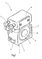
- FIG. 4 shows a perspective view of the reading head 2 of a Safety switch with a locking system 1 according to the invention (FIG. 4).
- the reading head 2 is at least part of the not shown Safety switch.
- the electrical switching function can be within the Head housing 4 are performed or in one of the head housing 4th arranged remote switch part of the safety switch.
- the electric Contacting of the reading head 2 takes place via one or more Connector 5.
- the head housing 4 is substantially parallelepiped with a substantially rectangular front surface 6. In a lower Area, the head housing 4 has a circular cylindrical bore, whose Longitudinal axis with the front surface 6 includes a right angle and in the electromagnet 7 can be used.
- the read head 2 by means of the head housing 4 at a Frame of the safety device or the machine (not shown) self-determined.
- the electromagnet 7 has a substantially circular cylindrical housing on, on its the actuator 3 side facing a substantially circular first contact surface 8 forms. Radial on the outside forms the Housing of the electromagnet 7 an annular edge 9 made of the first contact surface 8 is spaced by an annular groove 28.
- the first contact surface 8, the annular edge 9 and the front surface 6 are preferably in a plane plane.
- the first assembly 10 is fixed immovably in the head housing 4, in particular releasably screwed to the head housing 4.
- the wiring between the first assembly 10, the electromagnet 7 and the connector for the connector 5 is preferably carried out within the head housing 4.
- a cable clamp 11 for fixing the leads for the connector 5 is arranged on a side surface of the head housing 4.
- the preferably planar front surface or third contact surface 23 (FIG. 5) of the first assembly 10 is in alignment with the first contact surface 8 or is set back slightly therefrom.
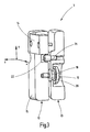
- Fig. 2 shows a perspective view of an associated actuator 3.
- the actuator 3 has a counter element 12, for example made of steel, with the actuator 3 on the read head 2 by the electromagnet. 7 fixable and thus the protective device is sustainable.
- the counter element 12 may be made in one piece of steel or only partially, for example, under Forming a frame made of aluminum to accommodate a with the Electromagnet co-operating insert.
- the counter element 12 is with an associated primitive 13, for example Aluminum, firmly connected, but pivotable opposite, as with The following description of FIGS. 3 to 5 will be explained. With the first assembly 10 of the read head 2 electrically contactless in Interaction engageable second assembly 14 is fixed to the Counter element 12 connected, preferably detachable means Fixing screws fixed to this.
- the counter-element 12 forms a plane second contact surface 15, which at the tumbler to the first contact surface 8 of the reading head 2 in planar Plant can be brought.
- the preferably flat front surface or fourth Bearing surface 24 (Fig. 5) of the second assembly 14 is aligned with the second Contact surface 15 or is set back slightly opposite this. It is essential that by the arrangement of the first and second Assembly 10, 14 contacting the first and second abutment surface 8, 15 of the electromagnet 7 and the counter-element 12 is ensured because this particularly high locking forces can be achieved.
- the actuator 3 is, for example, by means of the base member 13 at a Protective device for a switchable from the safety switch Machine set. Opposite this guard is the Counter element 12 together with the second assembly 14 to the three in 2 and each shown a right angle enclosing spatial directions x, y, z pivotally.
- the distance direction between counter element 12 and base member 13 is thereby through the Spatial direction z represents.
- In this distance direction z is Counter element 12 relative to the base member 13 is not substantially displaceable.
- Both the counter element 12 and the base element 13 have a substantially cuboidal basic shape with rounded edges and corners.
- the groove-shaped recesses 16 in Counter element 12 serve the accessibility for fasteners, in particular screws, which are in the mounting holes 17 in Base element 13 are inserted and by means of which the actuator 3 on the movable part of the protective device can be fixed.
- the second assembly 14 No connection lines, so that an electrical contact of the Actuator 3 is not required.
- first assembly 10 energy in the second assembly 14 in Actuator 3 transmitted to stored in the second assembly 14 read identification data and the first assembly 10 back to transfer.
- the second assembly 14 also only one generated by the first assembly 10 dampen electromagnetic field in a predeterminable manner and thereby the first module 10 and the read head 2, the presence of the second Assembly 14 and thus the closed position of the protective device Show.
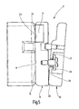
- Fig. 3 shows a perspective view of a section through the Actuator 3. It can be seen in particular the articulation of the Counter element 12 on the base element 13. On the counter element 12th facing away from the base element 13 for this purpose a bore, in the bottom surface 27 (FIG. 5) has a passage opening to the Counterelement 12 facing side of the base member 13 is provided is.
- a resiliently deformable element 18th arranged, in particular knotted, by the on the counter element 12th a this in a basic position relative to the base element 13th restoring force is exercisable.
- the elastically deformable element 18 by a rubber or rubber grommet Plastic formed by a the base element 13 with the Counterelement 12 connecting connecting element 19 passes.
- a washer 20 is arranged to the Protection of the elastically deformable element 18 against mechanical Overuse.
- the connecting element 19 is a detachable and preferably self-locking connection screw, which in a corresponding Threaded hole in the counter element 12 can be screwed.
- the counter element 12 is opposite the basic element 13 only within one of a mechanical Swivel stop device predeterminable range.
- the mechanical Anchoring device is in the illustrated embodiment by a Stop screw 21 realized, which also as a threaded pin, turned part, hard Cylinder pin, clamping sleeve or the like, can be performed. These Stop screw 21 protrudes into an associated stop opening 22, on the base element 13 facing surface of the counter element 12 is arranged and whose geometric dimensions ultimately the Determine the swivel range around the z axis.
- the stopper has a damping device to in Operation of Zuhaltesystems 1 a noise due to the Butting the components of the stopper to avoid, for example by interposition of elastic deformable elements.
- the Stop screw 21 and a corresponding threaded pin a wear damping O-ring and / or in the stop opening 22 a be arranged corresponding damping ring.
- the washer 20 is formed substantially pot-shaped and forms a stop especially when locking and the associated power transmission from the counter element 12 via the connecting element 19 on the base member 13, and thus from the read head 2 on the actuator 3 and the guard, and / or when screwing in the connecting element 19 and / or during pivoting of the counter element 12 relative to the base element 13.
- the grommet 18 is both in contact with the base member 13 and on the connecting element 12, and attenuates the vibration tendency of the counter element 12 and 12 when vibration or shock occurs thereby prevents noise or rattling, for example, caused by a striking of the counter element 12 on the base element 13th
- Fig. 5 shows a section similar to Fig. 4, but in the deflected State of the actuator 3.
- this is resiliently deformable element 18 not shown in this illustration. It can be seen, however, that when pivoting the counter element shown 12 with respect to the base member 13, the plane plant of the second Bearing surface 15 of the counter-element 12 at the first contact surface 8 of the Electromagnet 7 and thus high locking forces are ensured.
- the third contact surface 23 of the first assembly 10 in flat contact with the fourth contact surface 24 of the second module 14 and this is a safe electromagnetic interaction between the first and second assembly 10, 14 guaranteed.
- the pivoting range of the counter element 12 relative to the base element 13, in the case illustrated by the spatial direction x perpendicular to Plane in Fig. 5, is limited by the fact that compared to Swivel axis projecting and the base element 13 facing surface 25 of the counter element 12 in contact with the counter element 12th facing end face 26 of the base member 13 comes.
- the washer 20 with her cup-shaped edge at least one point in contact with the bottom surface 27 of the basic element 13.
Applications Claiming Priority (3)
| Application Number | Priority Date | Filing Date | Title |
|---|---|---|---|
| DE10146828 | 2001-09-18 | ||
| DE10146828A DE10146828A1 (de) | 2001-09-18 | 2001-09-18 | Zuhaltesystem eines Sicherheitsschalters mit einem Lesekopf und einem Betätiger |
| PCT/EP2002/010402 WO2003025963A1 (de) | 2001-09-18 | 2002-09-17 | Zuhaltesystem eines sicherheitsschalters mit einem lesekopf und einem betätiger |
Publications (2)
| Publication Number | Publication Date |
|---|---|
| EP1430497A1 EP1430497A1 (de) | 2004-06-23 |
| EP1430497B1 true EP1430497B1 (de) | 2005-11-23 |
Family
ID=7699970
Family Applications (1)
| Application Number | Title | Priority Date | Filing Date |
|---|---|---|---|
| EP02798649A Expired - Lifetime EP1430497B1 (de) | 2001-09-18 | 2002-09-17 | Zuhaltesystem eines sicherheitsschalters mit einem lesekopf und einem betätiger |
Country Status (7)
| Country | Link |
|---|---|
| US (1) | US6989727B2 (es) |
| EP (1) | EP1430497B1 (es) |
| JP (1) | JP2005505893A (es) |
| AT (1) | ATE311013T1 (es) |
| DE (2) | DE10146828A1 (es) |
| ES (1) | ES2254779T3 (es) |
| WO (1) | WO2003025963A1 (es) |
Cited By (1)
| Publication number | Priority date | Publication date | Assignee | Title |
|---|---|---|---|---|
| US11677573B2 (en) | 2018-08-24 | 2023-06-13 | Phoenix Contact Gmbh & Co. Kg | Contactless PoE connector and contactless PoE connection system |
Families Citing this family (20)
| Publication number | Priority date | Publication date | Assignee | Title |
|---|---|---|---|---|
| DE10216225A1 (de) * | 2002-04-08 | 2003-10-30 | Euchner Gmbh & Co | Elektromagnetisches Zuhaltesystem eines Sicherheitsschalters |
| DE10348884A1 (de) * | 2003-10-14 | 2005-05-25 | Pilz Gmbh & Co. Kg | Sicherheitsschalter, insbesondere Not-Aus-Schalter, zum sicheren Abschalten eines gefahrbringenden Gerätes |
| US7336964B2 (en) * | 2005-07-12 | 2008-02-26 | Qwest Communications International Inc. | Correlating activities with the location of a mobile communications device systems and methods |
| DE502007000822D1 (de) * | 2006-10-23 | 2009-07-16 | Pilz Auslandsbeteiligungen Gmb | Zuhaltevorrichtung |
| US7554044B2 (en) * | 2007-04-03 | 2009-06-30 | Deere & Company | Self-configuring operator control |
| US7754985B2 (en) | 2007-04-03 | 2010-07-13 | Deere & Company | Electronic switch assembly with configurable functionality |
| DE102007020313B4 (de) | 2007-04-24 | 2010-01-28 | Euchner Gmbh + Co. Kg | Vorrichtung zum Überwachen des Zustandes einer Schutzeinrichtung einer Maschine |
| DE102008057436B8 (de) | 2008-11-07 | 2020-06-04 | Euchner Gmbh + Co. Kg | Anordnung mit einem einen Lesekopf aufweisenden Sicherheitsschalter und einem Betätiger |
| DE102009059050B4 (de) | 2009-12-15 | 2017-10-12 | Euchner Gmbh + Co. Kg | Zuhaltesystem für einen Sicherheitsschalter und Sicherheitsschalter mit einem solchen Zuhaltesystem |
| US8525686B2 (en) | 2010-05-28 | 2013-09-03 | Rockwell Automation Technologies, Inc. | Variable adjustable door latch |
| US8552875B2 (en) | 2010-05-28 | 2013-10-08 | Rockwell Automation Technologies, Inc. | Efficient and safe door locking control in power-off and power-on conditions |
| DE102010034472B4 (de) | 2010-08-05 | 2017-10-12 | Euchner Gmbh + Co. Kg | Zuhalteeinrichtung für eine Vorrichtung zum Überwachen des Zustandes einer Schutzeinrichtung einer Maschine |
| DE102012002767A1 (de) | 2012-02-11 | 2013-08-14 | Euchner Gmbh + Co. Kg | Vorrichtung zum Überwachen des Zustandes einer Einrichtung |
| DE102012002769B4 (de) | 2012-02-11 | 2014-01-02 | Euchner Gmbh + Co. Kg | Vorrichtung zum lösbaren Fixieren eines vorgebbaren Zustandes einer Einrichtung sowie Sicherheitsschalter mit einer solchen Vorrichtung |
| DE102012021968B4 (de) * | 2012-10-31 | 2015-10-22 | Euchner Gmbh + Co. Kg | Vorrichtung zum lösbaren Arretieren eines vorgebbaren Zustandes einer Einrichtung sowie Sicherheitsschalter mit einer solchen Vorrichtung |
| DE102012111342A1 (de) | 2012-11-23 | 2014-05-28 | Pilz Gmbh & Co. Kg | Schutztürüberwachungssystem |
| DE102013001546B4 (de) | 2013-01-30 | 2017-10-12 | Euchner Gmbh + Co. Kg | Vorrichtung zum lösbaren Arretieren eines vorgebbaren Zustandes einer Einrichtung sowie Sicherheitsschalter mit einer solchen Vorrichtung |
| DE102013011433A1 (de) | 2013-07-09 | 2015-01-15 | Euchner Gmbh + Co. Kg | Vorrichtung zum Ansteuern einer Zuhalteeinrichtung sowie Sicherheitsschalter mit einer solchen Vorrichtung |
| US10865050B2 (en) * | 2017-08-30 | 2020-12-15 | Honda Motor Co., Ltd. | Manufacturing process switch for triggering an event when opened |
| DE202017105331U1 (de) * | 2017-09-05 | 2018-12-06 | Krones Ag | Etikettiermaschine zum Etikettieren von Behältern |
Family Cites Families (10)
| Publication number | Priority date | Publication date | Assignee | Title |
|---|---|---|---|---|
| DE3309372A1 (de) * | 1983-03-16 | 1984-09-27 | Hans & Jos. Kronenberg Gmbh, 5060 Bergisch Gladbach | Sicherheitsschalter |
| DE3324242A1 (de) * | 1983-07-06 | 1985-01-17 | Zwicker + Hensel Elektronische Schalttechnik GmbH, 5960 Olpe | Naeherungsschaltgeraet |
| DE3412612A1 (de) * | 1984-04-04 | 1985-10-17 | Felten & Guilleaume Energietechnik GmbH, 5000 Köln | Druckfeste verriegelung fuer tueren von schaltzellen |
| DE3429647A1 (de) * | 1984-08-11 | 1986-02-20 | WIK Elektro-Hausgeräte-Vertriebsgesellschaft mbH & Co Produktionskommanditgesellschaft, 4300 Essen | Steckdose, insbesondere in eine wandsteckdose einsteckbare steckdose mit stecker |
| DE69033004T2 (de) * | 1989-04-14 | 1999-11-18 | Eja Engineering Plc Wigan | Sicherheitsschalteranordnung |
| DE3923663A1 (de) * | 1989-07-18 | 1991-01-24 | Kronenberg Gmbh H & J | Sicherheitsschalter mit ausloesbarer sperre |
| DE4328297C1 (de) * | 1993-08-23 | 1995-02-23 | Euchner & Co | Sicherheitsschalter |
| FR2750791B1 (fr) * | 1996-07-02 | 1998-10-09 | Schneider Electric Sa | Interrupteur de securite verrouillable par electroaimant |
| FR2755533B1 (fr) * | 1996-11-04 | 1998-12-24 | Schneider Electric Sa | Interrupteur de securite a tete pivotante |
| DE19919949C5 (de) * | 1999-04-30 | 2013-03-07 | BSH Bosch und Siemens Hausgeräte GmbH | Vorrichtung mit einem Sicherheitsschalter |
-
2001
- 2001-09-18 DE DE10146828A patent/DE10146828A1/de not_active Withdrawn
-
2002
- 2002-09-17 JP JP2003529491A patent/JP2005505893A/ja active Pending
- 2002-09-17 AT AT02798649T patent/ATE311013T1/de not_active IP Right Cessation
- 2002-09-17 DE DE50205063T patent/DE50205063D1/de not_active Expired - Lifetime
- 2002-09-17 ES ES02798649T patent/ES2254779T3/es not_active Expired - Lifetime
- 2002-09-17 US US10/473,124 patent/US6989727B2/en not_active Expired - Fee Related
- 2002-09-17 EP EP02798649A patent/EP1430497B1/de not_active Expired - Lifetime
- 2002-09-17 WO PCT/EP2002/010402 patent/WO2003025963A1/de active IP Right Grant
Cited By (1)
| Publication number | Priority date | Publication date | Assignee | Title |
|---|---|---|---|---|
| US11677573B2 (en) | 2018-08-24 | 2023-06-13 | Phoenix Contact Gmbh & Co. Kg | Contactless PoE connector and contactless PoE connection system |
Also Published As
| Publication number | Publication date |
|---|---|
| DE50205063D1 (de) | 2005-12-29 |
| US20040245855A1 (en) | 2004-12-09 |
| US6989727B2 (en) | 2006-01-24 |
| JP2005505893A (ja) | 2005-02-24 |
| WO2003025963A1 (de) | 2003-03-27 |
| ATE311013T1 (de) | 2005-12-15 |
| ES2254779T3 (es) | 2006-06-16 |
| EP1430497A1 (de) | 2004-06-23 |
| DE10146828A1 (de) | 2003-04-24 |
Similar Documents
| Publication | Publication Date | Title |
|---|---|---|
| EP1430497B1 (de) | Zuhaltesystem eines sicherheitsschalters mit einem lesekopf und einem betätiger | |
| EP1493230B1 (de) | Elekromagnetisches zuhaltesystem eines sicherheitsschalters | |
| EP0922821B1 (de) | Türöffner | |
| EP1862767B1 (de) | Sicherheits-Positionssensor für Zylinder, Zylinder mit einem solchen Positionssensor | |
| EP0937311A1 (de) | Vorrichtung zur befestigung eines entfernungssensors an einem kraftfahrzeug | |
| DE102005054643B3 (de) | Schließzylinder | |
| DE3710079A1 (de) | Elektrischer verriegelungsschalter | |
| EP3272976B1 (de) | Kopplungsmechanismus mit zwangsgeführtem kopplungselement für mechatronisches schliesssystem | |
| WO2005067145A1 (de) | Sicherheitsschalter zum überwachen einer schliessposition zweier relativ zueinander beweglicher teile | |
| DE10037003B4 (de) | System zum Prüfen einer Eingriffsberechtigung in rechnergestützte Steuereinrichtungen von Maschinen, Anlagen oder dergleichen | |
| EP1377765A1 (de) | Getriebe, insbesondere schneckengetriebe | |
| DE29808526U1 (de) | Elektrischer Steckverbinder | |
| DE212017000281U1 (de) | Relaisvorrichtung | |
| DE102008057436B4 (de) | Anordnung mit einem einen Lesekopf aufweisenden Sicherheitsschalter und einem Betätiger | |
| DE102012007023B4 (de) | Schlossvorrichtung zum Verhindern einer Kollision | |
| EP0469284B1 (de) | Montageelement | |
| EP1148326A2 (de) | Hall-Sensor-Druckmessgerät | |
| EP1098054A1 (de) | Elektromotorische Blockiervorrichtung | |
| EP1005263B1 (de) | Befestigungsvorrichtung für ein elektronisches Gerät oder dessen Tragrahmen in einem Frontplatten-Ausschnitt | |
| DE102011001719A1 (de) | Türschließersystem | |
| EP3514302A1 (de) | Türbeschlag und verfahren zum montieren eines türbeschlags | |
| DE19848311C2 (de) | Elektromotorische Blockiervorrichtung | |
| EP3442081B1 (de) | Steckverbindungsdose für den einsatz in bahnfahrzeugen | |
| DE102004047515B4 (de) | Gehäuse | |
| EP3291269A1 (de) | Sicherheitsschalter |
Legal Events
| Date | Code | Title | Description |
|---|---|---|---|
| PUAI | Public reference made under article 153(3) epc to a published international application that has entered the european phase |
Free format text: ORIGINAL CODE: 0009012 |
|
| 17P | Request for examination filed |
Effective date: 20030717 |
|
| AK | Designated contracting states |
Kind code of ref document: A1 Designated state(s): AT BE BG CH CY CZ DE DK EE ES FI FR GB GR IE IT LI LU MC NL PT SE SK TR |
|
| GRAP | Despatch of communication of intention to grant a patent |
Free format text: ORIGINAL CODE: EPIDOSNIGR1 |
|
| GRAS | Grant fee paid |
Free format text: ORIGINAL CODE: EPIDOSNIGR3 |
|
| GRAA | (expected) grant |
Free format text: ORIGINAL CODE: 0009210 |
|
| AK | Designated contracting states |
Kind code of ref document: B1 Designated state(s): AT BE BG CH CY CZ DE DK EE ES FI FR GB GR IE IT LI LU MC NL PT SE SK TR |
|
| PG25 | Lapsed in a contracting state [announced via postgrant information from national office to epo] |
Ref country code: IE Free format text: LAPSE BECAUSE OF FAILURE TO SUBMIT A TRANSLATION OF THE DESCRIPTION OR TO PAY THE FEE WITHIN THE PRESCRIBED TIME-LIMIT Effective date: 20051123 Ref country code: SK Free format text: LAPSE BECAUSE OF FAILURE TO SUBMIT A TRANSLATION OF THE DESCRIPTION OR TO PAY THE FEE WITHIN THE PRESCRIBED TIME-LIMIT Effective date: 20051123 Ref country code: CZ Free format text: LAPSE BECAUSE OF FAILURE TO SUBMIT A TRANSLATION OF THE DESCRIPTION OR TO PAY THE FEE WITHIN THE PRESCRIBED TIME-LIMIT Effective date: 20051123 Ref country code: FI Free format text: LAPSE BECAUSE OF FAILURE TO SUBMIT A TRANSLATION OF THE DESCRIPTION OR TO PAY THE FEE WITHIN THE PRESCRIBED TIME-LIMIT Effective date: 20051123 |
|
| REG | Reference to a national code |
Ref country code: GB Ref legal event code: FG4D Free format text: NOT ENGLISH |
|
| REG | Reference to a national code |
Ref country code: CH Ref legal event code: NV Representative=s name: ISLER & PEDRAZZINI AG Ref country code: CH Ref legal event code: EP |
|
| REF | Corresponds to: |
Ref document number: 50205063 Country of ref document: DE Date of ref document: 20051229 Kind code of ref document: P |
|
| REG | Reference to a national code |
Ref country code: IE Ref legal event code: FG4D Free format text: LANGUAGE OF EP DOCUMENT: GERMAN |
|
| PG25 | Lapsed in a contracting state [announced via postgrant information from national office to epo] |
Ref country code: GR Free format text: LAPSE BECAUSE OF FAILURE TO SUBMIT A TRANSLATION OF THE DESCRIPTION OR TO PAY THE FEE WITHIN THE PRESCRIBED TIME-LIMIT Effective date: 20060223 Ref country code: DK Free format text: LAPSE BECAUSE OF FAILURE TO SUBMIT A TRANSLATION OF THE DESCRIPTION OR TO PAY THE FEE WITHIN THE PRESCRIBED TIME-LIMIT Effective date: 20060223 Ref country code: BG Free format text: LAPSE BECAUSE OF FAILURE TO SUBMIT A TRANSLATION OF THE DESCRIPTION OR TO PAY THE FEE WITHIN THE PRESCRIBED TIME-LIMIT Effective date: 20060223 |
|
| REG | Reference to a national code |
Ref country code: SE Ref legal event code: TRGR |
|
| GBT | Gb: translation of ep patent filed (gb section 77(6)(a)/1977) |
Effective date: 20060327 |
|
| PG25 | Lapsed in a contracting state [announced via postgrant information from national office to epo] |
Ref country code: PT Free format text: LAPSE BECAUSE OF FAILURE TO SUBMIT A TRANSLATION OF THE DESCRIPTION OR TO PAY THE FEE WITHIN THE PRESCRIBED TIME-LIMIT Effective date: 20060424 |
|
| REG | Reference to a national code |
Ref country code: ES Ref legal event code: FG2A Ref document number: 2254779 Country of ref document: ES Kind code of ref document: T3 |
|
| REG | Reference to a national code |
Ref country code: IE Ref legal event code: FD4D |
|
| ET | Fr: translation filed | ||
| PLBI | Opposition filed |
Free format text: ORIGINAL CODE: 0009260 |
|
| 26 | Opposition filed |
Opponent name: K.A. SCHMERSAL GMBH & CO. Effective date: 20060821 |
|
| PG25 | Lapsed in a contracting state [announced via postgrant information from national office to epo] |
Ref country code: MC Free format text: LAPSE BECAUSE OF NON-PAYMENT OF DUE FEES Effective date: 20060930 |
|
| PLAX | Notice of opposition and request to file observation + time limit sent |
Free format text: ORIGINAL CODE: EPIDOSNOBS2 |
|
| NLR1 | Nl: opposition has been filed with the epo |
Opponent name: K.A. SCHMERSAL GMBH & CO. |
|
| PLAF | Information modified related to communication of a notice of opposition and request to file observations + time limit |
Free format text: ORIGINAL CODE: EPIDOSCOBS2 |
|
| PLBB | Reply of patent proprietor to notice(s) of opposition received |
Free format text: ORIGINAL CODE: EPIDOSNOBS3 |
|
| REG | Reference to a national code |
Ref country code: CH Ref legal event code: PCAR Free format text: ISLER & PEDRAZZINI AG;POSTFACH 1772;8027 ZUERICH (CH) |
|
| PG25 | Lapsed in a contracting state [announced via postgrant information from national office to epo] |
Ref country code: EE Free format text: LAPSE BECAUSE OF FAILURE TO SUBMIT A TRANSLATION OF THE DESCRIPTION OR TO PAY THE FEE WITHIN THE PRESCRIBED TIME-LIMIT Effective date: 20051123 |
|
| PG25 | Lapsed in a contracting state [announced via postgrant information from national office to epo] |
Ref country code: TR Free format text: LAPSE BECAUSE OF FAILURE TO SUBMIT A TRANSLATION OF THE DESCRIPTION OR TO PAY THE FEE WITHIN THE PRESCRIBED TIME-LIMIT Effective date: 20051123 Ref country code: LU Free format text: LAPSE BECAUSE OF NON-PAYMENT OF DUE FEES Effective date: 20060917 |
|
| PLCK | Communication despatched that opposition was rejected |
Free format text: ORIGINAL CODE: EPIDOSNREJ1 |
|
| PGFP | Annual fee paid to national office [announced via postgrant information from national office to epo] |
Ref country code: CH Payment date: 20080930 Year of fee payment: 7 Ref country code: ES Payment date: 20080902 Year of fee payment: 7 |
|
| PG25 | Lapsed in a contracting state [announced via postgrant information from national office to epo] |
Ref country code: CY Free format text: LAPSE BECAUSE OF FAILURE TO SUBMIT A TRANSLATION OF THE DESCRIPTION OR TO PAY THE FEE WITHIN THE PRESCRIBED TIME-LIMIT Effective date: 20051123 |
|
| PGFP | Annual fee paid to national office [announced via postgrant information from national office to epo] |
Ref country code: AT Payment date: 20080814 Year of fee payment: 7 Ref country code: FR Payment date: 20080812 Year of fee payment: 7 Ref country code: IT Payment date: 20080908 Year of fee payment: 7 Ref country code: NL Payment date: 20080930 Year of fee payment: 7 |
|
| PGFP | Annual fee paid to national office [announced via postgrant information from national office to epo] |
Ref country code: GB Payment date: 20080812 Year of fee payment: 7 |
|
| APBM | Appeal reference recorded |
Free format text: ORIGINAL CODE: EPIDOSNREFNO |
|
| APBP | Date of receipt of notice of appeal recorded |
Free format text: ORIGINAL CODE: EPIDOSNNOA2O |
|
| APAH | Appeal reference modified |
Free format text: ORIGINAL CODE: EPIDOSCREFNO |
|
| PGFP | Annual fee paid to national office [announced via postgrant information from national office to epo] |
Ref country code: BE Payment date: 20080901 Year of fee payment: 7 |
|
| APBQ | Date of receipt of statement of grounds of appeal recorded |
Free format text: ORIGINAL CODE: EPIDOSNNOA3O |
|
| PGFP | Annual fee paid to national office [announced via postgrant information from national office to epo] |
Ref country code: SE Payment date: 20081031 Year of fee payment: 7 |
|
| BERE | Be: lapsed |
Owner name: *EUCHNER G.M.B.H. + CO. K.G. Effective date: 20090930 |
|
| REG | Reference to a national code |
Ref country code: CH Ref legal event code: PL |
|
| EUG | Se: european patent has lapsed | ||
| GBPC | Gb: european patent ceased through non-payment of renewal fee |
Effective date: 20090917 |
|
| REG | Reference to a national code |
Ref country code: NL Ref legal event code: V1 Effective date: 20100401 |
|
| REG | Reference to a national code |
Ref country code: FR Ref legal event code: ST Effective date: 20100531 |
|
| PG25 | Lapsed in a contracting state [announced via postgrant information from national office to epo] |
Ref country code: AT Free format text: LAPSE BECAUSE OF NON-PAYMENT OF DUE FEES Effective date: 20090917 |
|
| PG25 | Lapsed in a contracting state [announced via postgrant information from national office to epo] |
Ref country code: FR Free format text: LAPSE BECAUSE OF NON-PAYMENT OF DUE FEES Effective date: 20090930 |
|
| PG25 | Lapsed in a contracting state [announced via postgrant information from national office to epo] |
Ref country code: BE Free format text: LAPSE BECAUSE OF NON-PAYMENT OF DUE FEES Effective date: 20090930 |
|
| PG25 | Lapsed in a contracting state [announced via postgrant information from national office to epo] |
Ref country code: LI Free format text: LAPSE BECAUSE OF NON-PAYMENT OF DUE FEES Effective date: 20090930 Ref country code: CH Free format text: LAPSE BECAUSE OF NON-PAYMENT OF DUE FEES Effective date: 20090930 Ref country code: NL Free format text: LAPSE BECAUSE OF NON-PAYMENT OF DUE FEES Effective date: 20100401 |
|
| PG25 | Lapsed in a contracting state [announced via postgrant information from national office to epo] |
Ref country code: GB Free format text: LAPSE BECAUSE OF NON-PAYMENT OF DUE FEES Effective date: 20090917 |
|
| PG25 | Lapsed in a contracting state [announced via postgrant information from national office to epo] |
Ref country code: IT Free format text: LAPSE BECAUSE OF NON-PAYMENT OF DUE FEES Effective date: 20090917 |
|
| PLAB | Opposition data, opponent's data or that of the opponent's representative modified |
Free format text: ORIGINAL CODE: 0009299OPPO |
|
| PG25 | Lapsed in a contracting state [announced via postgrant information from national office to epo] |
Ref country code: SE Free format text: LAPSE BECAUSE OF NON-PAYMENT OF DUE FEES Effective date: 20090918 |
|
| R26 | Opposition filed (corrected) |
Opponent name: K.A. SCHMERSAL GMBH & CO. Effective date: 20060821 |
|
| REG | Reference to a national code |
Ref country code: ES Ref legal event code: FD2A Effective date: 20111116 |
|
| PG25 | Lapsed in a contracting state [announced via postgrant information from national office to epo] |
Ref country code: ES Free format text: LAPSE BECAUSE OF NON-PAYMENT OF DUE FEES Effective date: 20090918 |
|
| APBU | Appeal procedure closed |
Free format text: ORIGINAL CODE: EPIDOSNNOA9O |
|
| PLBN | Opposition rejected |
Free format text: ORIGINAL CODE: 0009273 |
|
| STAA | Information on the status of an ep patent application or granted ep patent |
Free format text: STATUS: OPPOSITION REJECTED |
|
| 27O | Opposition rejected |
Effective date: 20121126 |
|
| REG | Reference to a national code |
Ref country code: DE Ref legal event code: R100 Ref document number: 50205063 Country of ref document: DE Effective date: 20121126 |
|
| REG | Reference to a national code |
Ref country code: DE Ref legal event code: R082 Ref document number: 50205063 Country of ref document: DE Representative=s name: RUCKH, RAINER, DIPL.-PHYS. DR.RER.NAT., DE |
|
| PGFP | Annual fee paid to national office [announced via postgrant information from national office to epo] |
Ref country code: DE Payment date: 20190820 Year of fee payment: 18 |
|
| REG | Reference to a national code |
Ref country code: DE Ref legal event code: R119 Ref document number: 50205063 Country of ref document: DE |
|
| PG25 | Lapsed in a contracting state [announced via postgrant information from national office to epo] |
Ref country code: DE Free format text: LAPSE BECAUSE OF NON-PAYMENT OF DUE FEES Effective date: 20210401 |