EP1426684A2 - Einrichtung zum Aufnehmen bzw. Aufbewahren und zum Entnehmen von festem, rieselfähigem Heizmaterial - Google Patents
Einrichtung zum Aufnehmen bzw. Aufbewahren und zum Entnehmen von festem, rieselfähigem Heizmaterial Download PDFInfo
- Publication number
- EP1426684A2 EP1426684A2 EP03450058A EP03450058A EP1426684A2 EP 1426684 A2 EP1426684 A2 EP 1426684A2 EP 03450058 A EP03450058 A EP 03450058A EP 03450058 A EP03450058 A EP 03450058A EP 1426684 A2 EP1426684 A2 EP 1426684A2
- Authority
- EP
- European Patent Office
- Prior art keywords
- screw
- storage container
- heating material
- suction line
- container
- Prior art date
- Legal status (The legal status is an assumption and is not a legal conclusion. Google has not performed a legal analysis and makes no representation as to the accuracy of the status listed.)
- Granted
Links
Images


Classifications
-
- F—MECHANICAL ENGINEERING; LIGHTING; HEATING; WEAPONS; BLASTING
- F23—COMBUSTION APPARATUS; COMBUSTION PROCESSES
- F23K—FEEDING FUEL TO COMBUSTION APPARATUS
- F23K3/00—Feeding or distributing of lump or pulverulent fuel to combustion apparatus
- F23K3/02—Pneumatic feeding arrangements, i.e. by air blast
-
- B—PERFORMING OPERATIONS; TRANSPORTING
- B65—CONVEYING; PACKING; STORING; HANDLING THIN OR FILAMENTARY MATERIAL
- B65G—TRANSPORT OR STORAGE DEVICES, e.g. CONVEYORS FOR LOADING OR TIPPING, SHOP CONVEYOR SYSTEMS OR PNEUMATIC TUBE CONVEYORS
- B65G53/00—Conveying materials in bulk through troughs, pipes or tubes by floating the materials or by flow of gas, liquid or foam
- B65G53/34—Details
- B65G53/40—Feeding or discharging devices
- B65G53/48—Screws or like rotary conveyors
Definitions
- the present invention relates to a device for picking up or storing and removing solid, pourable heating material, especially pellets Wood, with a storage container for the heating material and a removal device provided on or in the storage container for the heating material, which has at least one discharge line, in particular a suction line, for an application and conveying the heating material out of the storage container to an intermediate container or a heater and at least one feed opening for introducing the Has heating material in the reservoir.
- a discharge line in particular a suction line
- heating systems which with solid, free-flowing Heating material is operated, for example known, right next to the heating system a storage room to provide in which such heating material, for example Pellets made of wood.
- the feed of the heating material to the heating system or a boiler takes place, for example, via a Suction line, such as the AT-U 3734, the AT-B 405 875 or EP-A 1 052 456.
- a Suction line such as the AT-U 3734, the AT-B 405 875 or EP-A 1 052 456.
- the present invention aims to provide a device of the type mentioned in further training in that a reliable one if a separate storage container is provided Remove and in particular dose the heating material is enabled to thereby control the supply amount to simplify the heating material accordingly.
- the solution to these tasks is a facility of the beginning mentioned type essentially characterized in that a receiving opening arranged in the interior of the storage container a screw for conveying or Dosing of the heating material upstream to the receiving opening is.
- the suction line a screw for conveying or dosing the heating material is connected upstream, it is possible by simple control the drive or the conveying speed and thus the Flow rate of the screw that of the downstream heating system Heating material to be supplied according to the requirements to dose exactly.
- the snail at least partially from one immersed in the interior of the storage container Guide tube is surrounded. Because the Snail at least partially surrounded by a guide tube the dosing accuracy can be further known the dimensions of the screw and the associated delivery rate improve through the area of the guide tube.
- the screw over a Part of their length, for example at least one Third of its length, from the guide tube to the inside of the Storage container protrudes. Through the out of the guide tube prominent area will be a reliable recording of the Ensure heating material from inside the storage container, whereupon the heating material through the screw into the part of the screw surrounded by the guide tube and subsequently spread through the suction line becomes.
- a drive or a shaft for the screw through the guide tube is and a motor for driving the screw outside of the storage container is arranged.
- the receiving opening of the Suction line is connected to the guide tube and a Recording of the heating material directly on the in the guide tube arranged end of the screw into the suction line, like this another preferred embodiment corresponds to the device according to the invention.
- Heating material through the suction line is according to proposed a further preferred embodiment, that in the area of the receiving opening of the suction line Air supply opening for the transfer and taking of heating material from the screw into the intake opening of the suction line empties.
- the container is preferred according to another Embodiment proposed that the screw adjustable in particular height adjustable, in the suction line and / or the guide tube is mounted.
- the snail can also be targeted adjustment the position of the screw for a deployment of the Achieve heating material.
- the snail movable coupled to the suction line and / or the guide tube is.
- the snail can easily get in a movable piece of pipe at least partially stored be correspondingly movable with the suction line or the guide tube is screwed, so that at actuation of the screw, the desired vibration or Loosening effect results.
- Suction line and possibly the line for supplying Air in the area of the intake opening of the suction line on Guide tube are articulated or fixed, as is one further preferred embodiment of the invention Furnishing corresponds.
- the Removal device comprising the suction line, the Snail and the air supply line, detachable or removable especially in a central area of the upper cover surface the container is arranged or fixed, wherein to further simplify the design it is also preferably provided that the setting the removal device on the container via a plate-shaped Lid of the container takes place, which beyond at least one filling or loading opening for insertion of heating material in the reservoir.
- the storage container in its bottom area in particular has plate-shaped internals, which is based on outer peripheral wall areas funnel-like or truncated cone-shaped Taper the center of the bottom of the container.
- the snail in the area of the in-depth center, especially one Swamp, the bottom of the reservoir is arranged so that it is additionally ensured that in the area of the collection point for the heating material based on the proposed preferred shape of at least the bottom area of the Storage container the heating material can be removed.
- the storage container in a manner known per se is made of plastic, so that accordingly inexpensive, robust and robust storage containers Have them manufactured, which can also accommodate large quantities of heating material are suitable.
- the reservoir is formed with a stiffener inside.
- the storage container in a manner known per se is receptacle in the ground.
- Such in the ground Storage containers to be provided can also be used accordingly be provided outside a building, whereby only Care must be taken that a simple and small Suction line or suction conveyor and if necessary an additional air supply line into the interior of the storage container through simple openings in one Building wall must be run while, for example the drive motor for the screw in a simple manner a shaft in the area of the storage container and can be provided, taking into account the fact that only a small snail is used takes place, even with a correspondingly small building Drive unit that can be found enough.
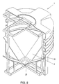
- Fig. 1 is generally a plastic, for example manufactured storage container, which, how this will be shown in more detail in Fig. 4, in its floor area with in particular plate-shaped internals 2 is provided, whereby a not shown, fixed inside the storage container 1 and pourable heating material, especially pellets Wood, in the area of the bottom center 27 of the container 1.
- a plastic, for example manufactured storage container which, how this will be shown in more detail in Fig. 4, in its floor area with in particular plate-shaped internals 2 is provided, whereby a not shown, fixed inside the storage container 1 and pourable heating material, especially pellets Wood, in the area of the bottom center 27 of the container 1.
- connection 5 for the removal of free-flowing Heating material from inside the storage container 1 over a schematically indicated line 6 to a heater or an intermediate container for a heater 7 is provided is.
- a supply line is via a connection 8 9 connected, via which preferably via a Blower or a pump 10 air over or into the removal device 4 is introduced, as follows will be discussed in more detail below.
- the storage container 1 shown in FIG. 1 is concerned for example, a container that can be held in the ground, so that on the lid 3 indicated by 11 filler neck via a shaft indicated schematically at 12 are accessible.
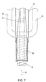
- the removal device 4 is a guide tube 13, which on Cover or the cover 3 is connected, wherein from the end 14 of the guide tube facing away from the cover 3 13 protrudes a screw conveyor 15, which over a schematically with 16 indicated drive or a shaft, which is guided inside the guide tube 13 via a motor, also indicated schematically at 17 a rotational movement is driven.
- a partial region of the screw conveyor projects 15 from the inside of the in Fig. 2 not closer illustrated reservoir provided end 14 of Guide tube 13 before, so that with a rotational movement of the Screw conveyor 15 schematically indicated by 18, free-flowing Heating material, especially wood pellets, added is and in the region of a receiving opening 19 Suction line 20 is promoted by which accordingly the arrow 21 the heating material from the inside of the container 1 is transported away.
- the connecting line to the downstream Heating or an intermediate container of the heater is again designated 6.
- Fig. 2 To support the removal through the suction line 20 is further indicated in Fig. 2 that there is an air supply line 22 in the area of the transfer of the heating material from the screw conveyor 15 into the receiving opening 19 likewise opens at or in the guide tube 13, the air introduction opening at 23 and the air supply direction at 24 is indicated.
- 3 is a modified embodiment of a turn shown generally with 4 removal device, again in the guide tube 13 a linkage or a shaft 16 for the screw 15 is supported, which in turn over a portion of its length, for example about a third, from the front end 14 of the Guide tube 13 protrudes.
- Heating material (not shown in more detail) is provided via the screw 15 conveyed from the inside of the container and dosed and gets into the suction line, again designated 20, in which hatches the heating material to be removed 25 is indicated.
- FIG. 4 schematically shows the bottom region 26 of the storage container 1, wherein it can be seen that plate-shaped Built-in fixtures 2 in total essentially form a funnel-like or truncated cone-shaped base area, in its center 27 in particular not closer shown screw 15 for proper removal or emptying the contents of the container 1 opens, such as this is indicated schematically in Fig. 1.
- FIG. 5 is a modified embodiment of a storage container 1 shown, which in addition to plate-shaped Internals 2 to increase the strength or rigidity the inside of the container with an internal reinforcement 28 or appropriate struts is provided. Furthermore is in the area of the funnel-like or truncated cone-shaped Tapering the center 27 of the bottom formed as a swamp in this sump 27 those not shown in FIG. 5 Removal screw is arranged.
- the screw conveyor 15 for receiving free-flowing heating material in particular Wood pellets, stored in a movable pipe section 29 is, which has schematically indicated screw connections 30 is movably connected to the guide tube 13.
- the screw 15 at least is partially supported in a rigid part 31, wherein through an adjustable height of the rigid part or Tube 31 together with the screw 15 relative to the guide tube 13 and / or a pipe part provided in turn 29 a complete residual emptying by an adjustment the screw 15 together with the rigid part 31 of the double arrow 32 is possible.
- a complete emptying can be done by the height adjustment the screw 15 according to the double arrow 36 also an adaptation to possibly varying ones Withdrawal conditions from the inside of the not shown Achieve container.
Landscapes
- Engineering & Computer Science (AREA)
- Mechanical Engineering (AREA)
- Chemical & Material Sciences (AREA)
- Combustion & Propulsion (AREA)
- General Engineering & Computer Science (AREA)
- Filling Or Emptying Of Bunkers, Hoppers, And Tanks (AREA)
- Processing And Handling Of Plastics And Other Materials For Molding In General (AREA)
- Screw Conveyors (AREA)
Abstract
Description
Claims (16)
- Einrichtung zum Aufnehmen bzw. Aufbewahren und zum Entnehmen von festem, rieselfähigem Heizmaterial, insbesondere Pellets aus Holz, mit einem Vorratsbehälter (1) für das Heizmaterial und einer am bzw. im Vorratsbehälter (1) vorgesehenen Entnahmevorrichtung (4) für das Heizmaterial, welche wenigstens eine Ausbringleitung (20), insbesondere eine Saugleitung, für ein Ausbringen und Fördern des Heizmaterials aus dem Vorratsbehälter (1) zu einem Zwischenbehälter oder einer Heizvorrichtung und wenigstens eine Zufuhröffnung (11) für ein Einbringen des Heizmaterials in den Vorratsbehälter (1) aufweist, dadurch gekennzeichnet, daß einer im Inneren des Vorratsbehälters (1) angeordneten Aufnahmeöffnung (19) der Saugleitung (20) eine Schnecke (15) zum Fördern bzw. Dosieren des Heizmaterials zu der Aufnahmeöffnung (19) vorgeschaltet ist.
- Einrichtung nach Anspruch 1, dadurch gekennzeichnet, daß die Schnecke (15) wenigstens teilweise von einem in das Innere des Vorratsbehälters (1) eintauchenden Führungsrohr (13) umgeben ist.
- Einrichtung nach Anspruch 2, dadurch gekennzeichnet, daß die Schnecke (15) über einen Teilbereich ihrer Länge, beispielsweise wenigstens ein Drittel ihrer Länge, aus dem Führungsrohr (13) in das Innere des Vorratsbehälters (1) vorragt.
- Einrichtung nach Anspruch 2 oder 3, dadurch gekennzeichnet, daß ein Antrieb bzw. eine Welle (16) für die Schnecke (15) durch das Führungsrohr (13) geführt ist und ein Motor (17) zum Antreiben der Schnecke (15) außerhalb des Vorratsbehälters (1) angeordnet ist.
- Einrichtung nach einem der Ansprüche 1 bis 4, dadurch gekennzeichnet, daß die Aufnahmeöffnung (19) der Saugleitung (20) an das Führungsrohr (13) angeschlossen ist und eine Aufnahme des Heizmaterials unmittelbar an dem im Führungsrohr (13) angeordneten Ende der Schnecke (15) in die Saugleitung (20) erfolgt.
- Einrichtung nach Anspruch 5, dadurch gekennzeichnet, daß im Bereich der Aufnahmeöffnung (19) der Saugleitung (20) eine Luftzufuhröffnung (23) zur Übergabe und Mitnahme von Heizmaterial von der Schnecke (15) in die Aufnahmeöffnung (19) der Saugleitung (20) mündet.
- Einrichtung nach einem der Ansprüche 1 bis 6, dadurch gekennzeichnet, daß die Schnecke (15) verstellbar, insbesondere höhenverstellbar, an der Saugleitung (20) und/oder dem Führungsrohr (13) gelagert ist.
- Einrichtung nach einem der Ansprüche 1 bis 7, dadurch gekennzeichnet, daß die Schnecke (15) beweglich mit der Saugleitung (20) und/oder dem Führungsrohr (13) gekoppelt ist.
- Einrichtung nach einem der Ansprüche 1 bis 8, dadurch gekennzeichnet, daß die Saugleitung (20) und gegebenenfalls die Leitung (22) zum Zuführen von Luft in dem Bereich der Aufnahmeöffnung (19) der Saugleitung (20) am Führungsrohr (13) angelenkt bzw. festgelegt sind.
- Einrichtung nach einem der Ansprüche 1 bis 9, dadurch gekennzeichnet, daß die Entnahmevorrichtung (4), umfassend die Saugleitung (20), die Schnecke (15) sowie die Luftzufuhrleitung (22), lösbar bzw. entfernbar insbesondere in einem mittigen Bereich der oberen Deckfläche des Behälters (1) angeordnet bzw. festgelegt ist.
- Einrichtung nach Anspruch 10, dadurch gekennzeichnet, daß die Festlegung der Entnahmevorrichtung (4) am Behälter (1) über einen plattenförmigen Deckel (3) des Behälters (1) erfolgt, welcher darüber hinaus wenigstens eine Befüll- bzw. Beschickungsöffnung (11) zum Einbringen von Heizmaterial in den Vorratsbehälter (1) aufweist.
- Einrichtung nach einem der Ansprüche 1 bis 11, dadurch gekennzeichnet, daß der Vorratsbehälter (1) in seinem Bodenbereich insbesondere plattenförmige Einbauten (2) aufweist, welche sich ausgehend von äußeren Umfangswandbereichen trichterartig bzw. kegelstumpfförmig im wesentlichen zum Zentrum (27) des Bodens des Behälters (1) verjüngen.
- Einrichtung nach Anspruch 12, dadurch gekennzeichnet, daß die Schnecke (15) im Bereich des vertieften Zentrums (27), insbesondere einem Sumpf, des Bodens des Vorratsbehälters (1) angeordnet ist.
- Einrichtung nach einem der Ansprüche 1 bis 13, dadurch gekennzeichnet, daß der Vorratsbehälter (1) in an sich bekannter Weise aus Kunststoff ausgebildet ist.
- Einrichtung nach einem der Ansprüche 1 bis 14, dadurch gekennzeichnet, daß der Vorratsbehälter (1) im Inneren mit einer Versteifung ausgebildet ist.
- Einrichtung nach einem der Ansprüche 1 bis 15, dadurch gekennzeichnet, daß der Vorratsbehälter (1) in an sich bekannter Weise ein im Erdreich aufnehmbarer Behälter ist.
Applications Claiming Priority (4)
| Application Number | Priority Date | Filing Date | Title |
|---|---|---|---|
| AT1402002 | 2002-03-06 | ||
| AT0014002U AT5854U1 (de) | 2002-03-06 | 2002-03-06 | Einrichtung zum aufnehmen bzw. aufbewahren und zum entnehmen von festem, rieselfähigem heizmaterial |
| DE20207200U | 2002-05-07 | ||
| DE20207200 | 2002-05-07 |
Publications (3)
| Publication Number | Publication Date |
|---|---|
| EP1426684A2 true EP1426684A2 (de) | 2004-06-09 |
| EP1426684A3 EP1426684A3 (de) | 2005-02-02 |
| EP1426684B1 EP1426684B1 (de) | 2010-07-07 |
Family
ID=32313386
Family Applications (1)
| Application Number | Title | Priority Date | Filing Date |
|---|---|---|---|
| EP03450058A Expired - Lifetime EP1426684B1 (de) | 2002-03-06 | 2003-02-28 | Einrichtung zum Aufnehmen bzw. Aufbewahren und zum Entnehmen von festem, rieselfähigem Heizmaterial |
Country Status (1)
| Country | Link |
|---|---|
| EP (1) | EP1426684B1 (de) |
Cited By (1)
| Publication number | Priority date | Publication date | Assignee | Title |
|---|---|---|---|---|
| AT511708B1 (de) * | 2011-10-13 | 2013-02-15 | Windhager Zentralheizung Technik Gmbh | Saugförderanlage für eine heizungsvorrichtung |
Families Citing this family (1)
| Publication number | Priority date | Publication date | Assignee | Title |
|---|---|---|---|---|
| DE202011051916U1 (de) | 2011-11-10 | 2012-11-15 | Viessmann Werke Gmbh & Co Kg | Speichervorrichtung |
Family Cites Families (5)
| Publication number | Priority date | Publication date | Assignee | Title |
|---|---|---|---|---|
| US4311102A (en) * | 1979-11-28 | 1982-01-19 | Kolze Melvin W | Burning system |
| WO1982003065A1 (en) * | 1981-03-10 | 1982-09-16 | Snowdon Brian | Conveying systems |
| DE3228468A1 (de) * | 1982-07-30 | 1984-02-09 | Thermo-Murg GmbH Apparatebau-Wärmetechnik, 7886 Murg | Verfahren zum einblasen von kohlenstaub oder dergleichen in brenner und feststoff-feuerungsvorrichtung dafuer |
| DD223796A1 (de) * | 1984-02-27 | 1985-06-19 | Komb Leipziger Metallbau Veb | Verfahren zur verbrennung von holzschleifstaub in industriellen feuerungen |
| ES2019358B3 (es) * | 1986-10-23 | 1991-06-16 | Warner-Lambert Company | Alimentador de polvo mejorado |
-
2003
- 2003-02-28 EP EP03450058A patent/EP1426684B1/de not_active Expired - Lifetime
Cited By (4)
| Publication number | Priority date | Publication date | Assignee | Title |
|---|---|---|---|---|
| AT511708B1 (de) * | 2011-10-13 | 2013-02-15 | Windhager Zentralheizung Technik Gmbh | Saugförderanlage für eine heizungsvorrichtung |
| AT511708A4 (de) * | 2011-10-13 | 2013-02-15 | Windhager Zentralheizung Technik Gmbh | Saugförderanlage für eine heizungsvorrichtung |
| DE102012109605A1 (de) | 2011-10-13 | 2013-04-18 | Windhager Zentralheizung Technik Gmbh | Saugförderanlage für eine Heizungsvorrichtung |
| DE102012109605B4 (de) * | 2011-10-13 | 2014-09-25 | Windhager Zentralheizung Technik Gmbh | Saugförderanlage für eine Heizungsvorrichtung |
Also Published As
| Publication number | Publication date |
|---|---|
| EP1426684A3 (de) | 2005-02-02 |
| EP1426684B1 (de) | 2010-07-07 |
Similar Documents
| Publication | Publication Date | Title |
|---|---|---|
| DE69801097T2 (de) | Automatischer Futterverteiler für Hunde und Katzen | |
| DE1937729C3 (de) | Silo für körniges oder pulvriges Gut | |
| DE2642340A1 (de) | Vorrichtung zur behandlung von saatgut mit einer fluessigkeit | |
| DE102007044178A1 (de) | Pneumatische Sämaschine | |
| DE3907361A1 (de) | Pulverdosiergeraet | |
| EP1426684A2 (de) | Einrichtung zum Aufnehmen bzw. Aufbewahren und zum Entnehmen von festem, rieselfähigem Heizmaterial | |
| EP1152228A2 (de) | Dosiereinrichtung für das Befüllen von Gefässen mit kleinem Öffnungsquerschnitt | |
| EP2682527A2 (de) | Verfahren zum Befüllen und Entleeren eines Flüssigkeitstanks eines Streugeräts für Winterdienstfahrzeuge sowie Streugerät | |
| DE3347417A1 (de) | Vorrichtung zur aufbewahrung, dosierung und mischung von moertel-materialkomponenten und verfahren zum betrieb der vorrichtung | |
| DE20216346U1 (de) | Einrichtung zum Aufnehmen bzw. Aufbewahren und zum Entnehmen von festem, rieselfähigem Heizmaterial | |
| DE9319066U1 (de) | Mörtelmischmaschine | |
| DE19602443C2 (de) | Dosiervorrichtung, insbesondere für pulver- oder partikelförmige Reinigungsmittel | |
| EP1593296A1 (de) | Streuvorrichtung, insbesondere für die Ausbringung von fein- bis grobkörnigem Mineraldünger | |
| DE4328071A1 (de) | Vorrichtung zur Entnahme von schwerfließenden Schüttgütern aus einem Silo | |
| DE4480790C1 (de) | Vorrichtung zum Wiederaufbereiten von Restbeton mit einer Förderschnecke | |
| DE102004020100A1 (de) | Verfahren und Vorrichtung zur pneumatischen Förderung von Schüttgut | |
| DE3541455C2 (de) | ||
| DE202009011341U1 (de) | Frischbrei-Automat | |
| DE19845168C2 (de) | Vorrichtung zum automatischen Füttern von Kälbern | |
| EP1520948A2 (de) | Fördervorrichtung, mobile Befüllanlage und Verfahren zum Einblasen von Dämmstoff in Dämmstoffkammern | |
| DE3606649C2 (de) | ||
| DE8337563U1 (de) | Vorrichtung zur Aufbewahrung, Dosierung und Mischung von Mörtel-Materialkomponenten | |
| DE68902809T2 (de) | Einrichtung zum foerdern eines pastoesen stoffes. | |
| WO2021204332A1 (de) | Tierfüttervorrichtung zum automatischen füttern | |
| DE3541704A1 (de) | Verfahren zum herstellen einer fuer die fluessigfuetterung geeigneten aufschwemmung aus silage und fluessigkeit und vorrichtung zur durchfuehrung des verfahrens |
Legal Events
| Date | Code | Title | Description |
|---|---|---|---|
| PUAI | Public reference made under article 153(3) epc to a published international application that has entered the european phase |
Free format text: ORIGINAL CODE: 0009012 |
|
| AK | Designated contracting states |
Kind code of ref document: A2 Designated state(s): AT BE BG CH CY CZ DE DK EE ES FI FR GB GR HU IE IT LI LU MC NL PT SE SI SK TR |
|
| AX | Request for extension of the european patent |
Extension state: AL LT LV MK RO |
|
| PUAL | Search report despatched |
Free format text: ORIGINAL CODE: 0009013 |
|
| AK | Designated contracting states |
Kind code of ref document: A3 Designated state(s): AT BE BG CH CY CZ DE DK EE ES FI FR GB GR HU IE IT LI LU MC NL PT SE SI SK TR |
|
| AX | Request for extension of the european patent |
Extension state: AL LT LV MK RO |
|
| RIC1 | Information provided on ipc code assigned before grant |
Ipc: 7F 23K 3/02 A Ipc: 7B 65G 53/08 B |
|
| 17P | Request for examination filed |
Effective date: 20050627 |
|
| AKX | Designation fees paid |
Designated state(s): AT BE BG CH CY CZ DE DK EE ES FI FR GB GR HU IE IT LI LU MC NL PT SE SI SK TR |
|
| RAP1 | Party data changed (applicant data changed or rights of an application transferred) |
Owner name: FRIEDRICH SCHOELS |
|
| GRAP | Despatch of communication of intention to grant a patent |
Free format text: ORIGINAL CODE: EPIDOSNIGR1 |
|
| GRAS | Grant fee paid |
Free format text: ORIGINAL CODE: EPIDOSNIGR3 |
|
| GRAA | (expected) grant |
Free format text: ORIGINAL CODE: 0009210 |
|
| AK | Designated contracting states |
Kind code of ref document: B1 Designated state(s): AT BE BG CH CY CZ DE DK EE ES FI FR GB GR HU IE IT LI LU MC NL PT SE SI SK TR |
|
| REG | Reference to a national code |
Ref country code: GB Ref legal event code: FG4D Free format text: NOT ENGLISH |
|
| REG | Reference to a national code |
Ref country code: CH Ref legal event code: EP |
|
| REG | Reference to a national code |
Ref country code: CH Ref legal event code: NV Representative=s name: PATENTS & TECHNOLOGY SURVEYS SA |
|
| REG | Reference to a national code |
Ref country code: IE Ref legal event code: FG4D |
|
| REF | Corresponds to: |
Ref document number: 50312859 Country of ref document: DE Date of ref document: 20100819 Kind code of ref document: P |
|
| REG | Reference to a national code |
Ref country code: NL Ref legal event code: VDEP Effective date: 20100707 |
|
| PG25 | Lapsed in a contracting state [announced via postgrant information from national office to epo] |
Ref country code: SI Free format text: LAPSE BECAUSE OF FAILURE TO SUBMIT A TRANSLATION OF THE DESCRIPTION OR TO PAY THE FEE WITHIN THE PRESCRIBED TIME-LIMIT Effective date: 20100707 |
|
| PG25 | Lapsed in a contracting state [announced via postgrant information from national office to epo] |
Ref country code: FI Free format text: LAPSE BECAUSE OF FAILURE TO SUBMIT A TRANSLATION OF THE DESCRIPTION OR TO PAY THE FEE WITHIN THE PRESCRIBED TIME-LIMIT Effective date: 20100707 Ref country code: NL Free format text: LAPSE BECAUSE OF FAILURE TO SUBMIT A TRANSLATION OF THE DESCRIPTION OR TO PAY THE FEE WITHIN THE PRESCRIBED TIME-LIMIT Effective date: 20100707 |
|
| REG | Reference to a national code |
Ref country code: IE Ref legal event code: FD4D |
|
| PG25 | Lapsed in a contracting state [announced via postgrant information from national office to epo] |
Ref country code: CY Free format text: LAPSE BECAUSE OF FAILURE TO SUBMIT A TRANSLATION OF THE DESCRIPTION OR TO PAY THE FEE WITHIN THE PRESCRIBED TIME-LIMIT Effective date: 20100707 Ref country code: BG Free format text: LAPSE BECAUSE OF FAILURE TO SUBMIT A TRANSLATION OF THE DESCRIPTION OR TO PAY THE FEE WITHIN THE PRESCRIBED TIME-LIMIT Effective date: 20101007 Ref country code: PT Free format text: LAPSE BECAUSE OF FAILURE TO SUBMIT A TRANSLATION OF THE DESCRIPTION OR TO PAY THE FEE WITHIN THE PRESCRIBED TIME-LIMIT Effective date: 20101108 |
|
| PG25 | Lapsed in a contracting state [announced via postgrant information from national office to epo] |
Ref country code: SE Free format text: LAPSE BECAUSE OF FAILURE TO SUBMIT A TRANSLATION OF THE DESCRIPTION OR TO PAY THE FEE WITHIN THE PRESCRIBED TIME-LIMIT Effective date: 20100707 Ref country code: GR Free format text: LAPSE BECAUSE OF FAILURE TO SUBMIT A TRANSLATION OF THE DESCRIPTION OR TO PAY THE FEE WITHIN THE PRESCRIBED TIME-LIMIT Effective date: 20101008 |
|
| REG | Reference to a national code |
Ref country code: CH Ref legal event code: PFA Owner name: FRIEDRICH SCHOELS Free format text: FRIEDRICH SCHOELS#ENGERTHSTRASSE 14#2604 THERESIENFELD (AT) -TRANSFER TO- FRIEDRICH SCHOELS#ENGERTHSTRASSE 14#2604 THERESIENFELD (AT) |
|
| PG25 | Lapsed in a contracting state [announced via postgrant information from national office to epo] |
Ref country code: DK Free format text: LAPSE BECAUSE OF FAILURE TO SUBMIT A TRANSLATION OF THE DESCRIPTION OR TO PAY THE FEE WITHIN THE PRESCRIBED TIME-LIMIT Effective date: 20100707 Ref country code: IE Free format text: LAPSE BECAUSE OF FAILURE TO SUBMIT A TRANSLATION OF THE DESCRIPTION OR TO PAY THE FEE WITHIN THE PRESCRIBED TIME-LIMIT Effective date: 20100707 |
|
| PLBE | No opposition filed within time limit |
Free format text: ORIGINAL CODE: 0009261 |
|
| STAA | Information on the status of an ep patent application or granted ep patent |
Free format text: STATUS: NO OPPOSITION FILED WITHIN TIME LIMIT |
|
| PG25 | Lapsed in a contracting state [announced via postgrant information from national office to epo] |
Ref country code: EE Free format text: LAPSE BECAUSE OF FAILURE TO SUBMIT A TRANSLATION OF THE DESCRIPTION OR TO PAY THE FEE WITHIN THE PRESCRIBED TIME-LIMIT Effective date: 20100707 Ref country code: SK Free format text: LAPSE BECAUSE OF FAILURE TO SUBMIT A TRANSLATION OF THE DESCRIPTION OR TO PAY THE FEE WITHIN THE PRESCRIBED TIME-LIMIT Effective date: 20100707 Ref country code: CZ Free format text: LAPSE BECAUSE OF FAILURE TO SUBMIT A TRANSLATION OF THE DESCRIPTION OR TO PAY THE FEE WITHIN THE PRESCRIBED TIME-LIMIT Effective date: 20100707 |
|
| PGFP | Annual fee paid to national office [announced via postgrant information from national office to epo] |
Ref country code: CH Payment date: 20110214 Year of fee payment: 9 |
|
| 26N | No opposition filed |
Effective date: 20110408 |
|
| PG25 | Lapsed in a contracting state [announced via postgrant information from national office to epo] |
Ref country code: ES Free format text: LAPSE BECAUSE OF FAILURE TO SUBMIT A TRANSLATION OF THE DESCRIPTION OR TO PAY THE FEE WITHIN THE PRESCRIBED TIME-LIMIT Effective date: 20101018 |
|
| REG | Reference to a national code |
Ref country code: DE Ref legal event code: R097 Ref document number: 50312859 Country of ref document: DE Effective date: 20110408 |
|
| BERE | Be: lapsed |
Owner name: FRIEDRICH SCHOLS Effective date: 20110228 |
|
| PG25 | Lapsed in a contracting state [announced via postgrant information from national office to epo] |
Ref country code: MC Free format text: LAPSE BECAUSE OF NON-PAYMENT OF DUE FEES Effective date: 20110228 |
|
| PG25 | Lapsed in a contracting state [announced via postgrant information from national office to epo] |
Ref country code: BE Free format text: LAPSE BECAUSE OF NON-PAYMENT OF DUE FEES Effective date: 20110228 |
|
| REG | Reference to a national code |
Ref country code: CH Ref legal event code: PL |
|
| PG25 | Lapsed in a contracting state [announced via postgrant information from national office to epo] |
Ref country code: CH Free format text: LAPSE BECAUSE OF NON-PAYMENT OF DUE FEES Effective date: 20120229 Ref country code: LI Free format text: LAPSE BECAUSE OF NON-PAYMENT OF DUE FEES Effective date: 20120229 |
|
| PG25 | Lapsed in a contracting state [announced via postgrant information from national office to epo] |
Ref country code: LU Free format text: LAPSE BECAUSE OF NON-PAYMENT OF DUE FEES Effective date: 20110228 |
|
| PG25 | Lapsed in a contracting state [announced via postgrant information from national office to epo] |
Ref country code: TR Free format text: LAPSE BECAUSE OF FAILURE TO SUBMIT A TRANSLATION OF THE DESCRIPTION OR TO PAY THE FEE WITHIN THE PRESCRIBED TIME-LIMIT Effective date: 20100707 |
|
| PG25 | Lapsed in a contracting state [announced via postgrant information from national office to epo] |
Ref country code: HU Free format text: LAPSE BECAUSE OF FAILURE TO SUBMIT A TRANSLATION OF THE DESCRIPTION OR TO PAY THE FEE WITHIN THE PRESCRIBED TIME-LIMIT Effective date: 20100707 |
|
| PGFP | Annual fee paid to national office [announced via postgrant information from national office to epo] |
Ref country code: AT Payment date: 20140210 Year of fee payment: 12 Ref country code: IT Payment date: 20140212 Year of fee payment: 12 |
|
| PGFP | Annual fee paid to national office [announced via postgrant information from national office to epo] |
Ref country code: GB Payment date: 20140226 Year of fee payment: 12 |
|
| REG | Reference to a national code |
Ref country code: AT Ref legal event code: MM01 Ref document number: 473399 Country of ref document: AT Kind code of ref document: T Effective date: 20150228 |
|
| GBPC | Gb: european patent ceased through non-payment of renewal fee |
Effective date: 20150228 |
|
| PG25 | Lapsed in a contracting state [announced via postgrant information from national office to epo] |
Ref country code: AT Free format text: LAPSE BECAUSE OF NON-PAYMENT OF DUE FEES Effective date: 20150228 |
|
| PG25 | Lapsed in a contracting state [announced via postgrant information from national office to epo] |
Ref country code: IT Free format text: LAPSE BECAUSE OF NON-PAYMENT OF DUE FEES Effective date: 20150228 |
|
| PG25 | Lapsed in a contracting state [announced via postgrant information from national office to epo] |
Ref country code: GB Free format text: LAPSE BECAUSE OF NON-PAYMENT OF DUE FEES Effective date: 20150228 |
|
| REG | Reference to a national code |
Ref country code: FR Ref legal event code: PLFP Year of fee payment: 14 |
|
| REG | Reference to a national code |
Ref country code: FR Ref legal event code: PLFP Year of fee payment: 15 |
|
| PGFP | Annual fee paid to national office [announced via postgrant information from national office to epo] |
Ref country code: FR Payment date: 20170213 Year of fee payment: 15 |
|
| REG | Reference to a national code |
Ref country code: FR Ref legal event code: ST Effective date: 20181031 |
|
| PG25 | Lapsed in a contracting state [announced via postgrant information from national office to epo] |
Ref country code: FR Free format text: LAPSE BECAUSE OF NON-PAYMENT OF DUE FEES Effective date: 20180228 |
|
| PGFP | Annual fee paid to national office [announced via postgrant information from national office to epo] |
Ref country code: DE Payment date: 20220105 Year of fee payment: 20 |
|
| REG | Reference to a national code |
Ref country code: DE Ref legal event code: R071 Ref document number: 50312859 Country of ref document: DE |