EP1423645B1 - Ensemble amortisseur concu pour reduire les pulsations d'une chambre de combustion dans une installation de turbine a gaz - Google Patents
Ensemble amortisseur concu pour reduire les pulsations d'une chambre de combustion dans une installation de turbine a gaz Download PDFInfo
- Publication number
- EP1423645B1 EP1423645B1 EP02758740A EP02758740A EP1423645B1 EP 1423645 B1 EP1423645 B1 EP 1423645B1 EP 02758740 A EP02758740 A EP 02758740A EP 02758740 A EP02758740 A EP 02758740A EP 1423645 B1 EP1423645 B1 EP 1423645B1
- Authority
- EP
- European Patent Office
- Prior art keywords
- combustion chamber
- wall
- surface part
- damping arrangement
- arrangement according
- Prior art date
- Legal status (The legal status is an assumption and is not a legal conclusion. Google has not performed a legal analysis and makes no representation as to the accuracy of the status listed.)
- Expired - Lifetime
Links
Images


Classifications
-
- F—MECHANICAL ENGINEERING; LIGHTING; HEATING; WEAPONS; BLASTING
- F23—COMBUSTION APPARATUS; COMBUSTION PROCESSES
- F23R—GENERATING COMBUSTION PRODUCTS OF HIGH PRESSURE OR HIGH VELOCITY, e.g. GAS-TURBINE COMBUSTION CHAMBERS
- F23R3/00—Continuous combustion chambers using liquid or gaseous fuel
- F23R3/002—Wall structures
-
- F—MECHANICAL ENGINEERING; LIGHTING; HEATING; WEAPONS; BLASTING
- F23—COMBUSTION APPARATUS; COMBUSTION PROCESSES
- F23M—CASINGS, LININGS, WALLS OR DOORS SPECIALLY ADAPTED FOR COMBUSTION CHAMBERS, e.g. FIREBRIDGES; DEVICES FOR DEFLECTING AIR, FLAMES OR COMBUSTION PRODUCTS IN COMBUSTION CHAMBERS; SAFETY ARRANGEMENTS SPECIALLY ADAPTED FOR COMBUSTION APPARATUS; DETAILS OF COMBUSTION CHAMBERS, NOT OTHERWISE PROVIDED FOR
- F23M20/00—Details of combustion chambers, not otherwise provided for, e.g. means for storing heat from flames
- F23M20/005—Noise absorbing means
-
- F—MECHANICAL ENGINEERING; LIGHTING; HEATING; WEAPONS; BLASTING
- F23—COMBUSTION APPARATUS; COMBUSTION PROCESSES
- F23R—GENERATING COMBUSTION PRODUCTS OF HIGH PRESSURE OR HIGH VELOCITY, e.g. GAS-TURBINE COMBUSTION CHAMBERS
- F23R2900/00—Special features of, or arrangements for continuous combustion chambers; Combustion processes therefor
- F23R2900/00014—Reducing thermo-acoustic vibrations by passive means, e.g. by Helmholtz resonators
Definitions
- the invention relates to a damping arrangement for reducing resonant vibrations in a combustion chamber with a double-walled combustion chamber wall, which encloses a gap gastight with an outer wall surface portion and an inner, the combustion chamber facing wall surface part, in the cooling air for purposes of convective cooling of the combustion chamber wall can be fed.
- a combustion chamber with an aforementioned double-walled combustion chamber wall is, for example, from the EP 0 669 500 B1 and DE-196 40 980-A1 out.
- the double-walled combustion chamber wall surrounding the combustion zone is traversed in its enclosed space for cooling purposes with compressed combustion air supply, wherein the double-walled combustion chamber wall is cooled by means of convective cooling. Further details about the design of such a combustion chamber can be found in the above-mentioned European patent in detail, is pointed to the disclosure content at this point.
- Such trained combustors are primarily for the operation of gas turbines, but they also find general use in heat-generating facilities, such as for firing of boilers.
- thermoacoustic oscillations occur in these combustion chambers, which in the frequency range between 20 and 400 Hz show quite pronounced resonance phenomena.
- combustion chamber pulsations oscillations can assume amplitudes and associated pressure fluctuations, whereby the combustion chamber itself is exposed to strong mechanical loads that are able to reduce the life of the combustion chamber crucial, even lead to the destruction of the combustion chamber.
- acoustic damping elements such as Helmholtz dampers or ⁇ / 4 tubes.
- a damping element is for example from the DE-19640 980-A1 out.
- acoustic damping elements consist of a bottleneck and a larger volume connected to the bottleneck, which in each case is adapted to the frequency to be damped.
- the targeted damping low frequencies requires large damping volume, which can not be integrated in each combustion chamber from a design point of view.
- Active countermeasures are also known for the targeted control of combustion chamber pulsations, with which, for example, anti-sound fields are coupled into the combustion chamber for targeted suppression or annihilation of the resonant pressure fluctuations.
- the combustion chamber described above with convective cooling within the double-walled combustion chamber wall has been optimized in the light of a low-emission combustion. Moreover, with such a combustor, it is possible to achieve very lean combustion using a relatively high proportion of air.
- damping measures with which an effective damping of itself within a combustion chamber of the type described above forming combustion chamber pulsations is possible without affecting the combustion optimized properties of the combustion chamber sustainable.
- damping measures whose constructive requirements build as small as possible in order to integrate them to save space in combustor systems of the aforementioned type. In particular, this should leave open the possibility to integrate the combustion chamber in systems that have only limited space.
- a damping arrangement for reducing resonant vibrations in a combustion chamber with a double-walled combustion chamber wall which encloses a gap in an airtight manner with an outer wall surface part and an inner wall surface part facing the combustion chamber, in FIG the cooling air for purposes of convective cooling of the combustion chamber wall can be fed, designed such that at least a third wall surface part is provided which includes a gas-tight volume with the outer wall surface portion and the gas-tight volume is gas-tightly connected to the combustion chamber via at least one connecting line.
- the third wall surface part supplements the already double-walled combustion chamber wall, at least locally or in sections, to form a three-walled wall structure, wherein the volume trapped by the outer wall surface part of the double-walled combustion chamber wall and the third wall surface part serves as resonance volume or absorber volume, ie. is formed in such a form and size that on the connecting line designed as a connecting line between the resonant or absorber volume - hereinafter referred to only as absorber volume - and the combustion chamber an acoustically effective coupling of the absorber volume is created to the combustion chamber, so that a damping of a within the combustion chamber forming Brennschpulsation with a certain frequency is effectively possible.
- the particular shape and size choice also applies to the connecting tube itself, which must have a certain length and a certain cross-section for damping a desired frequency.
- connection line designed as a connecting tube passes through the space traversed by the cooling air gap of the double-walled combustion chamber and is also effectively cooled by the circulation with cooling air.
- This has the advantage that the connecting tube does not have to be flowed through separately for cooling purposes with air. Also, heating or overheating of the absorber volume from the side of the combustion chamber through the connecting tube can be precluded, especially as this, as mentioned above, undergoes effective cooling. Nevertheless, should the cooling effect of the connecting tube surrounding the cooling air cooling air on the connecting tube are not sufficient, so can a targeted flow through the connecting tube provide with cooling air for the lack of cooling effect.
- This additional cooling effect can be accomplished either with the cooling air from the gap and / or from outside the combustion chamber, for example. From the plenum through an opening within the third wall surface part. However, such a directed through the connecting tube cooling air flow should have a flow rate of less than 10 m / s.
- the actuating means designed as a stamp divides the absorber volume into two spatial regions, ie into a spatial region in front of and one behind the stamp surface with respect to the connecting tube, then the volume fraction behind the stamp surface does not contribute to the acoustic absorption or damping.
- the double-walled combustion chamber wall is composed of two wall surface parts, both of which can be produced by means of a casting process.
- the inner wall surface part provides so-called longitudinal ribs as spacers and retaining ribs as fastening webs, by which both wall surface parts can be firmly connected while maintaining an exact distance.
- the connecting conduits formed as connecting tubes are provided along an already provided retaining rib, so that the connecting tube and the retaining rib can be made as a one-piece assembly together with the inner wall surface portion in a single casting step. This measure also facilitates the casting technology production of the inner wall surface part with a precisely predetermined wall surface thickness considerably, thereby also large-scale wall surface parts can be realized with a predetermined constant dimensioning without thickness deviations.
- Fig. 1 shows a cross-sectional partial view of a damping arrangement for reducing resonant vibrations in a combustion chamber 1, which is surrounded by a double-walled combustion chamber wall 2, which encloses a gap 3 gas-tight with an outer wall surface portion 22 and an inner wall surface portion 21, in the cooling air for purposes of convective cooling of the combustion chamber wall 2, in particular of the inner wall surface part 21 can be fed.
- a third wall surface portion 4 is provided, which includes a gas-tight volume, the so-called resonance or absorber volume 5 with the outer wall surface part 22.
- the absorber volume 5 Via a connecting line 6, in the form of a connecting tube, the absorber volume 5 is connected directly to the combustion chamber 1 and at the same time provides an acoustic operative connection between the combustion chamber 1 and the absorber volume 5 ago.
- the geometric sizes of the connecting line 6 and the absorber volume 5 are individually adapted.
- the inner and outer wall surface part 21 and 22 are manufactured by casting, wherein the wall surface part 21 longitudinal ribs 7, which serve as spacers and provide a predetermined exact distance between the outer wall surface part 22 and the inner wall surface part 21. Furthermore, the inner wall surface part 21 usually provides retaining ribs 8, which are longer than the longitudinal ribs 7 and protrude through a corresponding opening 9 within the outer wall surface part 22 in the mounted state and are firmly connected to the wall surface part 22 by means of a gas-tight welded connection 10.
- the provided for the acoustic coupling of the absorber volume 5 to the volume of the combustion chamber 1 connecting line 6 is integrally united with the retaining rib 8, which is like the longitudinal rib 7 integrally connected to the inner wall surface part 21 and produced in a single casting process can.
- FIG. 2a shows the top view of the outer wall surface part 22 of a combustion chamber with locally applied thereto absorber volume 5, each bounded by a third wall surface part 4.
- Fig. 2b shows a sectional view along the section line AA in Fig. 2a , along the double-walled combustion chamber wall 2 and the third wall surface portions 4, which are respectively connected gas-tightly connected to the outer wall surface part 22.
- Each individual absorber volume 5 projects beyond a connecting line 6, which acoustically establishes effective connection between the absorber volume 5 and the combustion chamber 1.
- Fig. 2c shows a sectional view along section line BB in Fig. 2b showing a cross section through the combustion chamber wall 2. Clearly visible are the individual of the third wall surface part 4 bounded absorber volume 5, each individually overflow a connecting line 6 gas-tight.
- a stamp-like trained adjusting means 11 through which the acoustically effective volume 5 'can be varied continuously by appropriate linear movement (see double arrow representation).
- the acoustically effective volume 5 ' is connected to the combustion chamber 1 via two connecting lines 6 and is thus able to selectively attenuate combustion chamber pulsations forming within the combustion chamber 1 according to the frequency.
- a plurality of connecting lines are preferably provided along the combustion chamber within the double-walled combustion chamber wall.
- the connecting lines are just to provide straight at those points of the combustion chamber at which form oscillation bellies.
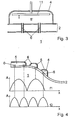
- the corresponding, introduced within the combustion chamber wall 2 connecting lines 6 are provided in the combustion chamber longitudinal axis x at those points at which combustion chamber vibrations each with different Frequencies f1, f2 have amplitude maxima.
- one or more connecting lines 6 can be combined in a common absorber volume 5. From the FIG. 4 also shows that only a certain frequency can be effectively damped per absorber volume.
- the absorber volumes are arranged axially one behind the other on the combustion chamber housing.
- the absorber volume distributed to attenuation of different frequencies in the circumferential direction of the combustion chamber housing.
Landscapes
- Engineering & Computer Science (AREA)
- Chemical & Material Sciences (AREA)
- Combustion & Propulsion (AREA)
- Mechanical Engineering (AREA)
- General Engineering & Computer Science (AREA)
- Fluidized-Bed Combustion And Resonant Combustion (AREA)
- Soundproofing, Sound Blocking, And Sound Damping (AREA)
Claims (13)
- Ensemble amortisseur pour réduire les oscillations résonantes dans une chambre de combustion (1), comprenant une paroi de chambre de combustion (2) réalisée à double paroi, qui entoure de manière étanche aux gaz un espace intermédiaire (3) avec une partie de surface de paroi extérieure (22) et une partie de surface de paroi intérieure (21) tournée vers la chambre de combustion (1), de l'air de refroidissement pouvant être injecté dans l'espace intermédiaire (3) pour refroidir par convexion la paroi de chambre de combustion (2), caractérisé en ce qu'au moins une troisième partie de surface de paroi (4) est prévue et entoure un volume étanche aux gaz (5) avec la partie de surface de paroi extérieure (22), et en ce que le volume étanche aux gaz (5) est connecté de manière étanche aux gaz à la chambre de combustion (1) par le biais d'au moins une conduite de connexion (6).
- Ensemble amortisseur selon la revendication 1, caractérisé en ce que la troisième partie de surface de paroi (4) est prévue du côté de la partie de surface de paroi extérieure (22) opposé à la chambre de combustion (1) et entoure le volume étanche aux gaz (5).
- Ensemble amortisseur selon la revendication 1 ou 2, caractérisé en ce que la troisième partie de surface de paroi (4) est connectée indirectement par le biais d'au moins un élément d'espacement ou directement à la partie de surface de paroi extérieure (22).
- Ensemble amortisseur selon l'une quelconque des revendications 1 à 3, caractérisé en ce que la paroi de chambre de combustion (2) à double paroi présente des nervures longitudinales (7) et/ou de fixation (8) pour l'espacement exact et/ou pour la fixation mutuelle de la partie de surface de paroi intérieure et de la partie de surface de paroi extérieure (21, 22), et en ce que la conduite de connexion (6) est prévue à l'endroit de la nervure longitudinale (7) et/ou de fixation (8) et est réalisée avec celle-ci sous forme d'unité constructive.
- Ensemble amortisseur selon la revendication 4, caractérisé en ce que les nervures longitudinales (7) et/ou de fixation (8) sont connectées d'une seule pièce à la paroi de chambre de combustion intérieure (21), qui peut être fabriquée au cours d'un procédé de coulage.
- Ensemble amortisseur selon l'une quelconque des revendications 1 à 5, caractérisé en ce que la conduite de connexion (6) est réalisée sous forme de petit tube de connexion, traverse l'espace intermédiaire (3) et peut être parcourue par de l'air de refroidissement.
- Ensemble amortisseur selon l'une quelconque des revendications 1 à 6, caractérisé en ce que le volume étanche aux gaz (5) est réalisé sous la forme d'un résonateur de Helmholtz, dont l'intensité volumique acoustiquement efficace (5') est obtenue en fonction de l'amortissement acoustique d'une oscillation se produisant à l'intérieur de la chambre de combustion (1) avec une fréquence de résonance f.
- Ensemble amortisseur selon la revendication 7, caractérisé en ce que l'on prévoit à l'intérieur du volume étanche aux gaz (5) un moyen de commande (11) pouvant régler de manière variable l'intensité volumique acoustiquement efficace.
- Ensemble amortisseur selon la revendication 8, caractérisé en ce que le moyen de commande (11) est réalisé sous forme de poinçon, qui est disposé de manière mobile à l'intérieur du volume étanche aux gaz (5).
- Ensemble amortisseur selon l'une quelconque des revendications 1 à 9, caractérisé en ce que la troisième partie de surface de paroi (4) est réalisée sous forme élastique.
- Ensemble amortisseur selon l'une quelconque des revendications 7 à 10, caractérisé en ce que la conduite de connexion (6) est disposée par rapport à la chambre de combustion (1) à l'endroit où l'oscillation acoustique à amortir présente un ventre d'oscillation.
- Installation de génération de chaleur ou d'énergie comprenant une chambre de combustion, caractérisée en ce que la chambre de combustion présente un ensemble amortisseur selon l'une quelconque des revendications 1 à 11.
- Chambre de combustion de turbine à gaz, caractérisée en ce qu'elle présente un ensemble amortisseur selon l'une quelconque des revendications 1 à 11.
Applications Claiming Priority (3)
| Application Number | Priority Date | Filing Date | Title |
|---|---|---|---|
| CH16632001 | 2001-09-07 | ||
| CH166301 | 2001-09-07 | ||
| PCT/IB2002/003492 WO2003023281A1 (fr) | 2001-09-07 | 2002-08-28 | Ensemble amortisseur concu pour reduire les pulsations d'une chambre de combustion dans une installation de turbine a gaz |
Publications (2)
| Publication Number | Publication Date |
|---|---|
| EP1423645A1 EP1423645A1 (fr) | 2004-06-02 |
| EP1423645B1 true EP1423645B1 (fr) | 2008-10-08 |
Family
ID=4565804
Family Applications (1)
| Application Number | Title | Priority Date | Filing Date |
|---|---|---|---|
| EP02758740A Expired - Lifetime EP1423645B1 (fr) | 2001-09-07 | 2002-08-28 | Ensemble amortisseur concu pour reduire les pulsations d'une chambre de combustion dans une installation de turbine a gaz |
Country Status (6)
| Country | Link |
|---|---|
| US (1) | US7104065B2 (fr) |
| EP (1) | EP1423645B1 (fr) |
| JP (1) | JP2005527761A (fr) |
| CN (1) | CN1250906C (fr) |
| DE (1) | DE50212871D1 (fr) |
| WO (1) | WO2003023281A1 (fr) |
Families Citing this family (55)
| Publication number | Priority date | Publication date | Assignee | Title |
|---|---|---|---|---|
| ITTO20031013A1 (it) * | 2003-12-16 | 2005-06-17 | Ansaldo Energia Spa | Sistema di smorzamento di instabilita' termoacustiche in un dispositivo combustore per una turbina a gas. |
| DE502004011481D1 (de) * | 2004-06-07 | 2010-09-16 | Siemens Ag | Brennkammer mit einer Dämpfungseinrichtung zur Dämpfung von thermoakustischen Schwingungen |
| US7334408B2 (en) * | 2004-09-21 | 2008-02-26 | Siemens Aktiengesellschaft | Combustion chamber for a gas turbine with at least two resonator devices |
| US7278256B2 (en) * | 2004-11-08 | 2007-10-09 | United Technologies Corporation | Pulsed combustion engine |
| EP1762786A1 (fr) | 2005-09-13 | 2007-03-14 | Siemens Aktiengesellschaft | Procédé et appareil pour réduire les vibrations thermo-accoustiques, en particulier dans une turbine |
| EP1862740B1 (fr) * | 2006-05-31 | 2015-09-16 | Siemens Aktiengesellschaft | Paroi de chambre de combustion |
| GB0610800D0 (en) * | 2006-06-01 | 2006-07-12 | Rolls Royce Plc | Combustion chamber for a gas turbine engine |
| JP4773904B2 (ja) * | 2006-07-11 | 2011-09-14 | 三菱重工業株式会社 | ガスタービン燃焼器 |
| US20090061369A1 (en) * | 2007-08-28 | 2009-03-05 | Gas Technology Institute | Multi-response time burner system for controlling combustion driven pulsation |
| JP4981615B2 (ja) * | 2007-10-19 | 2012-07-25 | 三菱重工業株式会社 | ガスタービン |
| US8151570B2 (en) * | 2007-12-06 | 2012-04-10 | Alstom Technology Ltd | Transition duct cooling feed tubes |
| EP2116770B1 (fr) * | 2008-05-07 | 2013-12-04 | Siemens Aktiengesellschaft | Atténuation dynamique de chambre de combustion et agencement de refroidissement |
| US9046269B2 (en) * | 2008-07-03 | 2015-06-02 | Pw Power Systems, Inc. | Impingement cooling device |
| US20100236245A1 (en) * | 2009-03-19 | 2010-09-23 | Johnson Clifford E | Gas Turbine Combustion System |
| EP2299177A1 (fr) * | 2009-09-21 | 2011-03-23 | Alstom Technology Ltd | Chambre de combustion de turbine à gaz |
| US8973365B2 (en) * | 2010-10-29 | 2015-03-10 | Solar Turbines Incorporated | Gas turbine combustor with mounting for Helmholtz resonators |
| US8720204B2 (en) | 2011-02-09 | 2014-05-13 | Siemens Energy, Inc. | Resonator system with enhanced combustor liner cooling |
| JP5693293B2 (ja) * | 2011-02-25 | 2015-04-01 | 三菱重工業株式会社 | 燃焼器 |
| EP2500648B1 (fr) * | 2011-03-15 | 2013-09-04 | Siemens Aktiengesellschaft | Chambre de combustion de turbines à gaz |
| JP5804808B2 (ja) * | 2011-07-07 | 2015-11-04 | 三菱日立パワーシステムズ株式会社 | ガスタービン燃焼器及びその燃焼振動減衰方法 |
| US8966903B2 (en) * | 2011-08-17 | 2015-03-03 | General Electric Company | Combustor resonator with non-uniform resonator passages |
| US20140345282A1 (en) * | 2011-09-01 | 2014-11-27 | Siemens Aktiengesellschaft | Combustion chamber for a gas turbine plant |
| US9395082B2 (en) * | 2011-09-23 | 2016-07-19 | Siemens Aktiengesellschaft | Combustor resonator section with an internal thermal barrier coating and method of fabricating the same |
| EP2818670B1 (fr) * | 2012-02-24 | 2017-09-20 | Mitsubishi Heavy Industries, Ltd. | Amortisseur acoustique, chambre de combustion et turbine à gaz |
| JP6071664B2 (ja) * | 2012-03-14 | 2017-02-01 | 三菱重工業株式会社 | 排気煙道 |
| EP2642204A1 (fr) | 2012-03-21 | 2013-09-25 | Alstom Technology Ltd | Amortissement à large bande simultanée à de multiples emplacements dans une chambre de combustion |
| US20130255260A1 (en) * | 2012-03-29 | 2013-10-03 | Solar Turbines Inc. | Resonance damper for damping acoustic oscillations from combustor |
| CN104204677B (zh) * | 2012-03-30 | 2016-07-06 | 通用电器技术有限公司 | 装备有阻尼装置的燃烧器密封段 |
| US20130283799A1 (en) * | 2012-04-25 | 2013-10-31 | Solar Turbines Inc. | Resonance damper for damping acoustic oscillations from combustor |
| US9447971B2 (en) * | 2012-05-02 | 2016-09-20 | General Electric Company | Acoustic resonator located at flow sleeve of gas turbine combustor |
| US8684130B1 (en) * | 2012-09-10 | 2014-04-01 | Alstom Technology Ltd. | Damping system for combustor |
| JP6231114B2 (ja) | 2012-10-24 | 2017-11-15 | ゼネラル エレクトリック テクノロジー ゲゼルシャフト ミット ベシュレンクテル ハフツングGeneral Electric Technology GmbH | 希釈ガス混合器を備えた2段燃焼 |
| WO2014133645A2 (fr) | 2013-02-20 | 2014-09-04 | Rolls-Royce North American Technologies Inc. | Turbine à gaz dotée d'un passage de dérivation configurable |
| KR101316202B1 (ko) * | 2013-03-12 | 2013-10-08 | 신대원보일러 주식회사 | 소각로용 워터자켓 |
| US20160076766A1 (en) * | 2013-04-23 | 2016-03-17 | Siemens Aktiengesellschaft | Combustion system of a flow engine and method for determining a dimension of a resonator cavity |
| EP2851618A1 (fr) * | 2013-04-24 | 2015-03-25 | Siemens Aktiengesellschaft | Système de combustion d'un moteur d'écoulement |
| EP2816288B1 (fr) | 2013-05-24 | 2019-09-04 | Ansaldo Energia IP UK Limited | Chambre de combustion de turbine à gaz avec amortisseur de vibrations |
| US9410484B2 (en) * | 2013-07-19 | 2016-08-09 | Siemens Aktiengesellschaft | Cooling chamber for upstream weld of damping resonator on turbine component |
| WO2015023576A1 (fr) * | 2013-08-15 | 2015-02-19 | United Technologies Corporation | Panneau de protection et cadre à cet effet |
| US10359194B2 (en) * | 2014-08-26 | 2019-07-23 | Siemens Energy, Inc. | Film cooling hole arrangement for acoustic resonators in gas turbine engines |
| EP3227611A1 (fr) * | 2014-12-01 | 2017-10-11 | Siemens Aktiengesellschaft | Résonateurs comprenant des tubes de mesure interchangeables pour des turbines à gaz |
| EP3029377B1 (fr) * | 2014-12-03 | 2018-04-11 | Ansaldo Energia Switzerland AG | Amortisseur pour une turbine à gaz |
| EP3032177B1 (fr) | 2014-12-11 | 2018-03-21 | Ansaldo Energia Switzerland AG | Ensemble de compensation pour un amortisseur d'une turbine à gaz |
| EP3048370A1 (fr) | 2015-01-23 | 2016-07-27 | Siemens Aktiengesellschaft | Chambre de combustion pour un moteur de turbine à gaz |
| CN104896514A (zh) * | 2015-05-13 | 2015-09-09 | 广东电网有限责任公司电力科学研究院 | 燃气轮机主燃烧室防振隔热壁 |
| DE102015215138A1 (de) * | 2015-08-07 | 2017-02-09 | Siemens Aktiengesellschaft | Brennkammer für eine Gasturbine mit mindestens einem Resonator |
| WO2018021996A1 (fr) | 2016-07-25 | 2018-02-01 | Siemens Aktiengesellschaft | Turbine à gaz à anneaux de résonateur |
| US20180209650A1 (en) * | 2017-01-24 | 2018-07-26 | Doosan Heavy Industries Construction Co., Ltd. | Resonator for damping acoustic frequencies in combustion systems by optimizing impingement holes and shell volume |
| JP7045851B2 (ja) * | 2017-12-28 | 2022-04-01 | 三菱重工業株式会社 | 燃焼器及びガスタービン |
| US11174792B2 (en) | 2019-05-21 | 2021-11-16 | General Electric Company | System and method for high frequency acoustic dampers with baffles |
| US11156164B2 (en) | 2019-05-21 | 2021-10-26 | General Electric Company | System and method for high frequency accoustic dampers with caps |
| DE102020200583A1 (de) * | 2020-01-20 | 2021-07-22 | Siemens Aktiengesellschaft | Resonatorring für Brennkammersysteme |
| CN116293795A (zh) * | 2021-12-06 | 2023-06-23 | 通用电气阿维奥有限责任公司 | 用于燃气涡轮燃烧器应用的圆顶集成声学阻尼器 |
| CN117109030A (zh) * | 2022-05-16 | 2023-11-24 | 通用电气公司 | 燃烧器衬里中的热声阻尼器 |
| US11898755B2 (en) * | 2022-06-08 | 2024-02-13 | General Electric Company | Combustor with a variable volume primary zone combustion chamber |
Family Cites Families (34)
| Publication number | Priority date | Publication date | Assignee | Title |
|---|---|---|---|---|
| US3705492A (en) * | 1971-01-11 | 1972-12-12 | Gen Motors Corp | Regenerative gas turbine system |
| FR2191025B1 (fr) * | 1972-07-04 | 1975-03-07 | Aerospatiale | |
| GB1581531A (en) * | 1976-09-09 | 1980-12-17 | Rolls Royce | Control of airflow in combustion chambers by variable rate diffuser |
| US4112676A (en) * | 1977-04-05 | 1978-09-12 | Westinghouse Electric Corp. | Hybrid combustor with staged injection of pre-mixed fuel |
| US4296606A (en) * | 1979-10-17 | 1981-10-27 | General Motors Corporation | Porous laminated material |
| US4297842A (en) * | 1980-01-21 | 1981-11-03 | General Electric Company | NOx suppressant stationary gas turbine combustor |
| JPS56124834A (en) * | 1980-03-05 | 1981-09-30 | Hitachi Ltd | Gas-turbine combustor |
| US4432207A (en) * | 1981-08-06 | 1984-02-21 | General Electric Company | Modular catalytic combustion bed support system |
| US5024058A (en) * | 1989-12-08 | 1991-06-18 | Sundstrand Corporation | Hot gas generator |
| JPH07501137A (ja) * | 1991-11-15 | 1995-02-02 | シーメンス アクチエンゲゼルシヤフト | ガスタービン設備の燃焼室内の燃焼振動抑制装置 |
| EP0576717A1 (fr) * | 1992-07-03 | 1994-01-05 | Abb Research Ltd. | Chambre de combustion de turbine à gaz |
| CA2141066A1 (fr) | 1994-02-18 | 1995-08-19 | Urs Benz | Procede de refroidissement d'une chambre de combustion a auto-allumage |
| US5737922A (en) * | 1995-01-30 | 1998-04-14 | Aerojet General Corporation | Convectively cooled liner for a combustor |
| DE19520291A1 (de) * | 1995-06-02 | 1996-12-05 | Abb Management Ag | Brennkammer |
| US5758504A (en) * | 1996-08-05 | 1998-06-02 | Solar Turbines Incorporated | Impingement/effusion cooled combustor liner |
| FR2752916B1 (fr) * | 1996-09-05 | 1998-10-02 | Snecma | Chemise de protection thermique pour chambre de combustion de turboreacteur |
| DE19640980B4 (de) * | 1996-10-04 | 2008-06-19 | Alstom | Vorrichtung zur Dämpfung von thermoakustischen Schwingungen in einer Brennkammer |
| GB2328011A (en) * | 1997-08-05 | 1999-02-10 | Europ Gas Turbines Ltd | Combustor for gas or liquid fuelled turbine |
| DE19751299C2 (de) * | 1997-11-19 | 1999-09-09 | Siemens Ag | Brennkammer sowie Verfahren zur Dampfkühlung einer Brennkammer |
| US6098397A (en) * | 1998-06-08 | 2000-08-08 | Caterpillar Inc. | Combustor for a low-emissions gas turbine engine |
| US6494044B1 (en) * | 1999-11-19 | 2002-12-17 | General Electric Company | Aerodynamic devices for enhancing sidepanel cooling on an impingement cooled transition duct and related method |
| US6973790B2 (en) * | 2000-12-06 | 2005-12-13 | Mitsubishi Heavy Industries, Ltd. | Gas turbine combustor, gas turbine, and jet engine |
| US6606861B2 (en) * | 2001-02-26 | 2003-08-19 | United Technologies Corporation | Low emissions combustor for a gas turbine engine |
| JP3962554B2 (ja) * | 2001-04-19 | 2007-08-22 | 三菱重工業株式会社 | ガスタービン燃焼器及びガスタービン |
| DE50107283D1 (de) * | 2001-06-18 | 2005-10-06 | Siemens Ag | Gasturbine mit einem Verdichter für Luft |
| JP4709433B2 (ja) * | 2001-06-29 | 2011-06-22 | 三菱重工業株式会社 | ガスタービン燃焼器 |
| DE10214570A1 (de) * | 2002-04-02 | 2004-01-15 | Rolls-Royce Deutschland Ltd & Co Kg | Mischluftloch in Gasturbinenbrennkammer mit Brennkammerschindeln |
| US6761031B2 (en) * | 2002-09-18 | 2004-07-13 | General Electric Company | Double wall combustor liner segment with enhanced cooling |
| US6826913B2 (en) * | 2002-10-31 | 2004-12-07 | Honeywell International Inc. | Airflow modulation technique for low emissions combustors |
| US7152411B2 (en) * | 2003-06-27 | 2006-12-26 | General Electric Company | Rabbet mounted combuster |
| US6955038B2 (en) * | 2003-07-02 | 2005-10-18 | General Electric Company | Methods and apparatus for operating gas turbine engine combustors |
| US7146815B2 (en) * | 2003-07-31 | 2006-12-12 | United Technologies Corporation | Combustor |
| US7114321B2 (en) * | 2003-07-31 | 2006-10-03 | General Electric Company | Thermal isolation device for liquid fuel components |
| US20050044857A1 (en) * | 2003-08-26 | 2005-03-03 | Boris Glezer | Combustor of a gas turbine engine |
-
2002
- 2002-08-28 CN CNB028174984A patent/CN1250906C/zh not_active Expired - Fee Related
- 2002-08-28 DE DE50212871T patent/DE50212871D1/de not_active Expired - Lifetime
- 2002-08-28 US US10/488,595 patent/US7104065B2/en not_active Expired - Fee Related
- 2002-08-28 JP JP2003527316A patent/JP2005527761A/ja not_active Withdrawn
- 2002-08-28 WO PCT/IB2002/003492 patent/WO2003023281A1/fr active Application Filing
- 2002-08-28 EP EP02758740A patent/EP1423645B1/fr not_active Expired - Lifetime
Also Published As
| Publication number | Publication date |
|---|---|
| DE50212871D1 (de) | 2008-11-20 |
| JP2005527761A (ja) | 2005-09-15 |
| US7104065B2 (en) | 2006-09-12 |
| CN1551965A (zh) | 2004-12-01 |
| WO2003023281A1 (fr) | 2003-03-20 |
| CN1250906C (zh) | 2006-04-12 |
| US20040248053A1 (en) | 2004-12-09 |
| EP1423645A1 (fr) | 2004-06-02 |
Similar Documents
| Publication | Publication Date | Title |
|---|---|---|
| EP1423645B1 (fr) | Ensemble amortisseur concu pour reduire les pulsations d'une chambre de combustion dans une installation de turbine a gaz | |
| EP2334558B1 (fr) | Silencieux pour un groupe auxiliaire d'un avion | |
| EP1158247B1 (fr) | Dispositif pour la réduction des vibrations accoustiques dans une chambre de combustion | |
| EP2167796B1 (fr) | Dispositif et procédé d'amélioration de l'atténuation d'ondes acoustiques | |
| DE10058688B4 (de) | Dämpferanordnung zur Reduktion von Brennkammerpulsationen | |
| EP0577862B1 (fr) | Dispositif de post-combustion | |
| DE19851636A1 (de) | Dämpfungsvorrichtung zur Reduzierung der Schwingungsamplitude akustischer Wellen für einen Brenner | |
| DE10325691A1 (de) | Wiederaufheizverbrennungssystem für eine Gasturbine | |
| EP1265029A2 (fr) | Ensemble brûleur | |
| EP0971172B1 (fr) | Chambre de combustion pour turbine à gaz avec paroi à structure silencieuse | |
| EP2500648B1 (fr) | Chambre de combustion de turbines à gaz | |
| EP0985882A1 (fr) | Amortissement des vibrations dans des combusteurs | |
| DE4316475A1 (de) | Gasturbinen-Brennkammer | |
| DE10040869A1 (de) | Verfahren und Vorrichtung zur Unterdrückung von Strömungswirbeln innerhalb einer Strömungskraftmaschine | |
| DE19640980A1 (de) | Vorrichtung zur Dämpfung von thermoakustischen Schwingungen in einer Brennkammer | |
| DE19948674B4 (de) | Verbrennungseinrichtung, insbesondere für den Antrieb von Gasturbinen | |
| EP1342953A1 (fr) | Turbine à gaz | |
| EP0892217B1 (fr) | Dispositif d'atténuation des vibrations d'une chambre de combustion | |
| EP2354659A1 (fr) | Amortisseur de Helmholtz pour l'intégration dans la chambre de combustion d'une turbine à gaz et procédé d'intégration d'un tel amortisseur de Helmholtz | |
| EP0990851B1 (fr) | Chambre de combustion pour une turbine à gaz | |
| DE2712326A1 (de) | Brenner | |
| EP1605209A1 (fr) | Chambre de combustion avec dispositif d'amortissement des vibrations thermo-acoustiques | |
| DE102004010620B4 (de) | Brennkammer zur wirksamen Nutzung von Kühlluft zur akustischen Dämpfung von Brennkammerpulsation | |
| DE102006040760A1 (de) | Gasturbinenbrennkammerwand für eine mager-brennende Gasturbinenbrennkammer | |
| DE19939235B4 (de) | Verfahren zum Erzeugen von heissen Gasen in einer Verbrennungseinrichtung sowie Verbrennungseinrichtung zur Durchführung des Verfahrens |
Legal Events
| Date | Code | Title | Description |
|---|---|---|---|
| PUAI | Public reference made under article 153(3) epc to a published international application that has entered the european phase |
Free format text: ORIGINAL CODE: 0009012 |
|
| 17P | Request for examination filed |
Effective date: 20040212 |
|
| AK | Designated contracting states |
Kind code of ref document: A1 Designated state(s): AT BE BG CH CY CZ DE DK EE ES FI FR GB GR IE IT LI LU MC NL PT SE SK TR |
|
| AX | Request for extension of the european patent |
Extension state: AL LT LV MK RO SI |
|
| RAP1 | Party data changed (applicant data changed or rights of an application transferred) |
Owner name: ALSTOM TECHNOLOGY LTD |
|
| GRAP | Despatch of communication of intention to grant a patent |
Free format text: ORIGINAL CODE: EPIDOSNIGR1 |
|
| GRAS | Grant fee paid |
Free format text: ORIGINAL CODE: EPIDOSNIGR3 |
|
| GRAA | (expected) grant |
Free format text: ORIGINAL CODE: 0009210 |
|
| AK | Designated contracting states |
Kind code of ref document: B1 Designated state(s): DE GB |
|
| REG | Reference to a national code |
Ref country code: GB Ref legal event code: FG4D Free format text: NOT ENGLISH |
|
| REF | Corresponds to: |
Ref document number: 50212871 Country of ref document: DE Date of ref document: 20081120 Kind code of ref document: P |
|
| PLBE | No opposition filed within time limit |
Free format text: ORIGINAL CODE: 0009261 |
|
| STAA | Information on the status of an ep patent application or granted ep patent |
Free format text: STATUS: NO OPPOSITION FILED WITHIN TIME LIMIT |
|
| 26N | No opposition filed |
Effective date: 20090709 |
|
| PGFP | Annual fee paid to national office [announced via postgrant information from national office to epo] |
Ref country code: DE Payment date: 20090821 Year of fee payment: 8 |
|
| REG | Reference to a national code |
Ref country code: DE Ref legal event code: R119 Ref document number: 50212871 Country of ref document: DE Effective date: 20110301 |
|
| PG25 | Lapsed in a contracting state [announced via postgrant information from national office to epo] |
Ref country code: DE Free format text: LAPSE BECAUSE OF NON-PAYMENT OF DUE FEES Effective date: 20110301 |
|
| REG | Reference to a national code |
Ref country code: GB Ref legal event code: 732E Free format text: REGISTERED BETWEEN 20170727 AND 20170802 |
|
| PGFP | Annual fee paid to national office [announced via postgrant information from national office to epo] |
Ref country code: GB Payment date: 20170822 Year of fee payment: 16 |
|
| GBPC | Gb: european patent ceased through non-payment of renewal fee |
Effective date: 20180828 |
|
| PG25 | Lapsed in a contracting state [announced via postgrant information from national office to epo] |
Ref country code: GB Free format text: LAPSE BECAUSE OF NON-PAYMENT OF DUE FEES Effective date: 20180828 |